EP2019289A2 - Intertial measurement unit with wireless power transfer gap control - Google Patents
Intertial measurement unit with wireless power transfer gap control Download PDFInfo
- Publication number
- EP2019289A2 EP2019289A2 EP08160119A EP08160119A EP2019289A2 EP 2019289 A2 EP2019289 A2 EP 2019289A2 EP 08160119 A EP08160119 A EP 08160119A EP 08160119 A EP08160119 A EP 08160119A EP 2019289 A2 EP2019289 A2 EP 2019289A2
- Authority
- EP
- European Patent Office
- Prior art keywords
- gas
- core
- measurement unit
- inertial measurement
- sensor
- Prior art date
- Legal status (The legal status is an assumption and is not a legal conclusion. Google has not performed a legal analysis and makes no representation as to the accuracy of the status listed.)
- Withdrawn
Links
Images


Classifications
-
- G—PHYSICS
- G01—MEASURING; TESTING
- G01C—MEASURING DISTANCES, LEVELS OR BEARINGS; SURVEYING; NAVIGATION; GYROSCOPIC INSTRUMENTS; PHOTOGRAMMETRY OR VIDEOGRAMMETRY
- G01C19/00—Gyroscopes; Turn-sensitive devices using vibrating masses; Turn-sensitive devices without moving masses; Measuring angular rate using gyroscopic effects
- G01C19/02—Rotary gyroscopes
- G01C19/04—Details
- G01C19/16—Suspensions; Bearings
-
- G—PHYSICS
- G01—MEASURING; TESTING
- G01C—MEASURING DISTANCES, LEVELS OR BEARINGS; SURVEYING; NAVIGATION; GYROSCOPIC INSTRUMENTS; PHOTOGRAMMETRY OR VIDEOGRAMMETRY
- G01C19/00—Gyroscopes; Turn-sensitive devices using vibrating masses; Turn-sensitive devices without moving masses; Measuring angular rate using gyroscopic effects
- G01C19/02—Rotary gyroscopes
- G01C19/04—Details
- G01C19/16—Suspensions; Bearings
- G01C19/20—Suspensions; Bearings in fluid
-
- G—PHYSICS
- G01—MEASURING; TESTING
- G01C—MEASURING DISTANCES, LEVELS OR BEARINGS; SURVEYING; NAVIGATION; GYROSCOPIC INSTRUMENTS; PHOTOGRAMMETRY OR VIDEOGRAMMETRY
- G01C21/00—Navigation; Navigational instruments not provided for in groups G01C1/00 - G01C19/00
- G01C21/10—Navigation; Navigational instruments not provided for in groups G01C1/00 - G01C19/00 by using measurements of speed or acceleration
- G01C21/12—Navigation; Navigational instruments not provided for in groups G01C1/00 - G01C19/00 by using measurements of speed or acceleration executed aboard the object being navigated; Dead reckoning
- G01C21/16—Navigation; Navigational instruments not provided for in groups G01C1/00 - G01C19/00 by using measurements of speed or acceleration executed aboard the object being navigated; Dead reckoning by integrating acceleration or speed, i.e. inertial navigation
- G01C21/166—Mechanical, construction or arrangement details of inertial navigation systems
-
- H—ELECTRICITY
- H02—GENERATION; CONVERSION OR DISTRIBUTION OF ELECTRIC POWER
- H02J—ELECTRIC POWER NETWORKS; CIRCUIT ARRANGEMENTS OR SYSTEMS FOR SUPPLYING OR DISTRIBUTING ELECTRIC POWER; SYSTEMS FOR STORING ELECTRIC ENERGY
- H02J50/00—Circuit arrangements or systems for wireless supply or distribution of electric power
- H02J50/90—Circuit arrangements or systems for wireless supply or distribution of electric power involving detection or optimisation of position, e.g. alignment
-
- H—ELECTRICITY
- H02—GENERATION; CONVERSION OR DISTRIBUTION OF ELECTRIC POWER
- H02J—ELECTRIC POWER NETWORKS; CIRCUIT ARRANGEMENTS OR SYSTEMS FOR SUPPLYING OR DISTRIBUTING ELECTRIC POWER; SYSTEMS FOR STORING ELECTRIC ENERGY
- H02J50/00—Circuit arrangements or systems for wireless supply or distribution of electric power
- H02J50/10—Circuit arrangements or systems for wireless supply or distribution of electric power using inductive coupling
-
- H—ELECTRICITY
- H02—GENERATION; CONVERSION OR DISTRIBUTION OF ELECTRIC POWER
- H02J—ELECTRIC POWER NETWORKS; CIRCUIT ARRANGEMENTS OR SYSTEMS FOR SUPPLYING OR DISTRIBUTING ELECTRIC POWER; SYSTEMS FOR STORING ELECTRIC ENERGY
- H02J50/00—Circuit arrangements or systems for wireless supply or distribution of electric power
- H02J50/70—Circuit arrangements or systems for wireless supply or distribution of electric power involving the reduction of electric, magnetic or electromagnetic leakage fields
Definitions
- Precision inertial navigation systems are used in civil and military aviation, missiles and other projectiles, submarines and other underwater vehicles, space exploration technology, as well as in numerous other vehicle applications.
- a typical inertial navigation system measures the position and attitude of a vehicle by measuring the accelerations and rotations applied to the vehicle's inertial frame of reference. Since the typical INS is not dependent on other points of reference, it is resistant to jamming and deception.
- An INS usually includes an inertial measurement unit (IMU) combined with control mechanisms, allowing the path of a vehicle to be controlled according to the position determined by the INS.
- An IMU contains instruments for position monitoring.
- a conventional INS requires concentric sets of ball bearing supported gimbals that allow instruments to freely rotate in vehicle maneuvers and further allow for manipulation during a calibration routine.
- An INS typically uses either gyrostablized platforms or 'strapdown' systems.
- the gyrostabilized system allows a vehicle's roll, pitch and yaw angles to be measured directly at the bearings of the gimbals.
- the INS is traditionally rotated using electromagnetic motors on a ball bearing supported gimbal axis. Disadvantages of this scheme is that it employs multiple expensive precision mechanical parts including moving parts that can wear out or jam, and is vulnerable to gimbal lock.
- another gimbal is required thus increasing the size and complexity of the INS. Therefore, to get complete three dimensional calibration, at least three gimbals are needed.
- a typical inertial sensor assembly (ISA) within the INS is an electronic device that contains internally embedded instrumentation (e.g., one or more accelerometers and gyroscopes) that communicates with other vehicle systems. Data from the internally embedded instrumentation is typically communicated to the other vehicle systems through moving contact devices, such as slip rings or twist caps.
- the slip rings and twist caps provide a constant communication link for the data without restricting the movement of the ISA.
- slip rings and twist caps are moving physical structures subject to wear. Multiple slip rings and twist caps represent potential failure points for the typical INS. Similarly, transferring supply power to the ISA through the multiple slip rings and twist caps is subject to interference due to electrical noise. Moreover, receiving the supply power through the moving contact devices is restricted in applications where the gimbals are absent and physical contact with the ISA is prohibited.
- the present invention is directed to an inertial measurement unit that comprises an outer case assembly including an upper gas plenum and a lower gas plenum.
- An upper support shell is surrounded by the upper gas plenum, with the upper support shell having a plurality of apertures.
- a lower support shell is surrounded by the lower gas plenum, with the lower support shell having a plurality of apertures.
- a sensor assembly includes a sensor shell having an outer surface, with the sensor assembly surrounded by the upper and lower support shells.
- a plurality of gas bearing pads extends through the apertures in the upper and lower support shells.
- the plurality of gas bearing pads are configured to receive a first pressurized gas from the upper and lower gas plenums and inject the first pressurized gas into a gap that separates the gas bearing pads and the sensor shell. This produces a first gas bearing that allows the sensor assembly to be freely suspended and rotated in all directions.
- the inertial measurement unit also comprises at least one wireless power transfer transformer that includes a power transmitting core mounted to the outer case assembly, and a power receiving core mounted in an opening of the sensor shell.
- the power receiving core is configured to be aligned with the power transmitting core for wireless power transfer.
- the power transmitting core is configured to inject a second pressurized gas into a gap between the power transmitting core and the power receiving core. This produces a second gas bearing that maintains a predetermined separation distance between the power transmitting core and the power receiving core during the wireless power transfer.
- the present invention is related to an inertial measurement unit (IMU) with wireless power transfer gap control.
- IMU inertial measurement unit
- An internal sensor assembly in the IMU is configured to rotate for self calibration. Power needs to be transmitted to the sensor assembly without limiting its rotational freedom and without a mechanical wear out mechanism. This is accomplished with a wireless power transfer transformer to induce a power transfer across a small gap. The smaller the gap, the higher the efficiency of the power transfer.
- This invention minimizes the gap by utilizing pressurized gas to act as a gas bearing between a pair of power transfer cores.
- a method for wireless power transfer in an inertial measurement unit generally comprises aligning a power receiving core in a sensor assembly with a power transmitting core external to the sensor assembly.
- a pressurized gas is injected through the power transmitting core into a controlled gap between the power transmitting core and the power receiving core to produce a gas bearing.
- a wireless power signal is then transmitted from the power transmitting core to the power receiving core.
- the gap is held to a very small distance by the film of gas acting as a bearing.
- Gas bearings have very stiff spring rates and operate with increased stiffness as the gap is decreased.
- the transmitting core has a spring loaded mounting stem that preloads the transmitting core toward the receiving core with the gas bearing opposing that spring force. This provides geometric alignment between the two cores and minimizes the gap with little if any need for manual adjustment.
- While the present invention is particularly useful in a precision inertial guidance system such as used in strategic missiles, other industrial air bearing or rotating element applications may also find use for the present gas bearing gap, such as to control the critical spacing of a wireless inductive power transfer system.
- FIG. 1 is a cutaway view of a stationary outer case assembly 100 for an IMU according to one embodiment.
- the outer case assembly 100 includes an upper gas plenum 102 and a lower gas plenum 104.
- the upper gas plenum 102 comprises an upper side portion 106 having a first thickness and an upper rim portion 108 having a second thickness that is greater than the first thickness of side portion 106.
- the lower gas plenum 104 comprises a lower side portion 110 having a first thickness and a lower rim portion 112 having a second thickness that is greater than the first thickness of side portion 110.
- the side portion 106 of upper gas plenum 102 gradually tapers in thickness to rim portion 108 that is adjacent to the top of outer case assembly 100.
- side portion 110 of lower gas plenum 104 also gradually tapers in thickness to rim portion 112 that is adjacent to the bottom of outer case assembly 100.
- the thicker rim portions 108, 112 of the gas plenums near the top and bottom of outer case assembly 100 are configured to handle the stress of high pressure gas in the plenums.
- the rim portions 108, 112 also define respective upper and lower gas outlets 114, 116 for gas exiting outer case assembly 100.
- the upper and lower gas plenums 102, 104 have respective plenum flanges 117, 118.
- the gas plenums 102, 104 can be adapted to provide radiation shielding for outer case assembly 100. Such radiation shielding is described in further detail in copending U.S. Application Serial No. (Honeywell Docket No. H0014141).
- An upper support shell 120 is surrounded by upper gas plenum 102 and has a plurality of apertures 121.
- a lower support shell 122 is surrounded by lower gas plenum 104 and has a plurality of apertures 123.
- the upper and lower support shells 120, 122 have respective shell flanges 124, 126 that are attached to a mounting plate 128 on upper and lower surfaces thereof.
- the plenum flanges 117, 118 are respectively attached to shell flanges 124, 126.
- the plenums flanges and shell flanges can be attached by any suitable fasteners such as bolts, screws, rivets, or the like.
- the upper and lower support shells 120, 122 have respective lip portions 130, 132 that are contiguous with rim portions 108, 112 of the gas plenums near the top and bottom of outer case assembly 100.
- the lip portions 130, 132 define respective top and bottom openings 134, 136 that communicate with upper and lower gas outlets 114, 116.
- the support shells 120, 122 are adapted to receive a plurality of individually adjustable gas bearing pads 140 through apertures 121, 123 in the support shells.
- the gas bearing pads 140 have hollow stems 142 that extend through apertures 121, 123.
- gas bearing pads 140 are adapted to be received into threaded apertures in support shells 120, 122. Further details of suitable gas bearing pads are described in copending U.S. Application Serial No. (Honeywell Docket No. H0014141).
- An upper gas chamber 144 is formed between upper gas plenum 102 and the outer surface of upper support shell 120.
- a lower gas chamber 146 is formed between lower gas plenum 104 and the outer surface of lower support shell 122.
- the gas chambers 144, 146 provide high pressure zones for gas that is injected into outer case assembly 100.
- An upper gas inlet is provided in mounting plate 128 and is in communication with upper gas chamber 144.
- a jet nozzle 150 is coupled to the upper gas inlet.
- a lower gas inlet is also provided in mounting plate 128 and is in communication with lower gas chamber 146.
- a jet nozzle is also coupled to the lower gas inlet.
- High pressure gas such as air or nitrogen, can be directed through the jet nozzles into the gas inlets and passes into the high pressure zones of gas chambers 144, 146, which are configured to distribute the pressurized gas evenly to gas bearing pads 140.
- a sensor shell 160 for a sensor assembly is surrounded by the upper and lower support shells 120, 122.
- sensor shell 160 includes internal fastening structures 162 that are configured to secure embedded instrumentation (not shown) within the sensor assembly, such as gyroscopes, accelerometers, and the like.
- the sensor shell 160 can have an outer surface with a substantially spherical shape such that the sensor assembly is in the form of a ball.
- the sensor shell 160 can be made from a metallic material such as aluminum.
- upper and lower support shells 120, 122 can have a substantially hemispherical shape.
- the upper and lower gas plenums 102, 104 also have a substantially hemispherical shape.
- the support shells and plenums are shown with a hemispherical shape to closely encase the spherical-shaped sensor shell, other shapes can be utilized depending on the shape of the sensor assembly.
- the outer sensor shell of the sensor assembly can have a cylindrical shape suited for encapsulating sensor instrumentation and allowing for suspension and rotation of the sensor assembly in a single axis of rotation.
- the support shells and plenums in this alternate embodiment would have a corresponding cylindrical shape to closely encase the sensor assembly.
- the upper and lower support shells 120, 122 have a larger diameter than sensor shell 160 to allow for mounting of gas bearing pads 140.
- the gas bearing pads 140 and the outer spherical surface of sensor shell 160 are separated by a narrow gap 164 when pressurized gas is fed through the gas bearing pads. This creates a gas bearing that allows sensor shell 160 to be freely suspended and rotated in all directions.
- a first pressure relief valve 170 is coupled to upper gas plenum 102 at flange 117 adjacent to jet nozzle 150.
- a second pressure relief valve 172 is coupled to lower gas plenum 104 at flange 118 also adjacent to jet nozzle 150.
- the flanges 117 and 118 adjacent to jet nozzle 150 define respective ports 174 and 176 that are in communication with gas chambers 144 and 146, respectively.
- the valves 170 and 172 are movably inserted into ports 174 and 176, respectively, to provide pressure relief for gas chambers 144 and 146.
- An O-ring 180 is disposed in a slot that circumscribes shell flange 124, and an O-ring 182 is disposed in a slot that circumscribes shell flange 126.
- the O-rings 180, 182 respectively provide a fluid-tight seal between shell flanges 124, 126 and plenum flanges 117, 118 attached thereto.
- An O-ring 184 is disposed in a slot on a surface of lip portion 130 of upper support shell 120 to provide a fluid-tight joint between lip portion 130 and rim portion 108 of gas plenum 102.
- An O-ring 186 is disposed in a slot on a surface of lip portion 132 of lower support shell 122 to provide a fluid-tight joint between lip portion 132 and rim portion 112 of gas plenum 104.
- a wireless power transfer transformer 210 is disposed in a high pressure gas inlet of mounting plate 128.
- the transformer 210 has a power transmitting core 212 including a hollow mounting stem 220 coupled to a spring cushion joint 222 and an gas pad 224.
- the transformer 210 also has a power receiving core (not shown).
- a hose can be coupled to stem 220 to provide pressurized gas to power transmitting core 212. Further details with respect to transformer 210 are discussed hereafter.
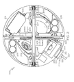
- FIG 2 is a cut away view of a sensor assembly 200 that has embedded instrumentation in a spherical sensor shell 201.
- the sensor assembly 200 can be implemented within the outer case assembly 100 of an IMU as shown in Figure 1 .
- the embedded instrumentation within sensor assembly 200 can include one or more gyroscopes 202, one or more accelerometers 204, a rechargeable power source such as one or more batteries 206, as well as other electronic components such as a processor.
- the gyroscopes sense rotation in any of three axes, and the accelerometers measure acceleration in any of three directions.
- An axle 207 is disposed in the middle of sensor assembly 200 and has two eccentric weights 208, 209 that point in opposite directions. This configuration for axle 208 provides an external balance mechanism for sensor assembly 200.
- the sensor assembly 200 is configured to communicate sensor data from the embedded instrumentation to a controller or processor for the IMU.
- the sensor data can include data collected from outputs of the embedded instrumentation, system health indicators and alarms (e.g., battery power level and component failure indications), and programming and control instructions for electronic components within the embedded instrumentation.
- the sensor assembly 200 can measure the position and attitude of a vehicle in which it is mounted by measuring the accelerations and rotations applied to the vehicle's inertial frame. For example, if sensor shell 201 rotates, the gyroscopes sense motion and transmit sensor data to the processor. If sensor shell 201 translates or moves, the accelerometers sense velocity/acceleration and send sensor data to the processor.
- the processor can calculate the position of the sensor shell and the direction it is pointed at any given time anywhere in space.
- the wireless power transfer transformer 210 has power transmitting core 212, which includes hollow mounting stem 220 coupled to spring cushion joint 222 and gas pad 224. As shown in Figure 2 , transformer 210 also includes a power receiving core 214 that is mounted in an opening of sensor shell 201, such that the outer surface of power receiving core 214 is flush with the outer surface of sensor shell 201.
- the power receiving core 214 is configured to be aligned with power transmitting core 212 for wireless power transfer in order to charge batteries 206. While only a single wireless power transfer transformer 210 is shown in Figures 1 and 2 , it should be understood that one or more additional wireless power transfer transformers can be implemented in different locations around sensor assembly 200 as desired.
- the receiving core 214 is coupled to charging coil electronics 226 in sensor assembly 200.
- the transmitting core 212 and receiving core 214 are separated by a narrow gap 230 that is maintained by high pressure gas supplied through mounting stem 220.
- the high pressure gas provides a gas bearing to keep transmitting core 212 and receiving core 214 separated.
- the nature of gas bearings is to have a small but firm gap between the two halves of the bearing.
- the present implementation creates the gas bearing with transmitting core 212 and receiving core 214 as the two halves of the bearing.
- the spring cushion joint 222 placed behind the transmitting core 212 allows for self adjustment of transmitting core 212 relative to receiving core 214 to account for tolerance and to continuously optimize gap 230 at all attitudes of the IMU.
- pressurized gas is directed through the jet nozzles and is distributed in the high pressure zones of gas chambers 144, 146.
- the pressurized gas is then fed through hollow stems 142 of bearing pads 140 from the gas chambers to provide a high pressure gas bearing between bearing pads 140 and the outer surface of sensor shell 160 (201).
- the gas bearing allows the sensor shell to rotate freely in a near frictionless environment, which provides for easy calibration of sensors in the sensor shell.
- a controller aligns receiving core 214 with transmitting core 212 to transfer wireless power signals from a power supply connected to the transmitting core.
- the bearing pads 140 keep sensor assembly 200 suspended to allow for rotation and alignment of receiving core 214 with transmitting core 212.
- transmitting core 212 and receiving core 214 are separated by the controlled gap having a gas bearing to complete the wireless power transfer.
- the controlled gap can provide a separation distance of about 0.001 inch (0.0254 mm) or less between the transmitting core and the receiving core. The separation distance of the gap is maintained at a precise value by the gas bearing created by the transmitting core, providing for efficient power transfer.
- FIG 3 is an exploded perspective view of a wireless power transfer transformer 310 according to one embodiment.
- the transformer 310 can be implemented in an IMU and sensor assembly such as described previously for transformer 210.
- the transformer 310 includes a casing mountable power transmitting core 312, and a power receiving core 314 that is mountable in a sensor assembly.
- the transmitting core 312 and receiving core 314 are configured to face each other during a power transfer and are separated by a controlled gap 316.
- the transmitting core 312 has a hollow mounting stem 320 defining a plenum that supplies high pressure gas.
- the stem 320 has an inlet 324 and an outlet 326.
- An elastomeric joint 328 having an opening therethrough is configured to cover outlet 326.
- the elastomeric joint 328 provides a spring cushion that allows for self alignment, axial motion, and radial adjustment of transmitting core 312 to adjust the controlled gap 316 based on gas pressure.
- a gas pad 330 is configured to mate with elastomeric joint 328 and stem 320 through receptacle 332.
- the gas pad 330 has a central hole for directing high pressure gas to controlled gap 316 to form a gas bearing therein.
- the gas flow path through transmitting core 312 is shown by the arrow G.
- the gas pad 330 has an outer surface 334 with a circular groove 336 for holding a single coil winding 338.
- the transmitting core 312 is configured to be electrically coupled to external charging coil electronics 340.
- the receiving core 314 has an outer surface 342 that faces outer surface 334 of gas pad 330.
- outer surface 334 of gas pad 330 has a substantially spherical concave shape
- outer surface 342 of receiving core 314 has a corresponding substantially spherical convex shape to allow controlled gap 316 to be as uniform as possible.
- the spherical convex shape of outer surface 342 is configured to match the outer curvature of a spherical sensor shell that utilizes transformer 310.
- the pressurized gas, the elastomeric joint, and the core curvatures all work in conjunction to provide a stationary, controlled gap 316.
- the outer surface 342 of receiving core 314 is configured to hold a single coil winding 344 that faces coil winding 338 of gas pad 330.
- the receiving core 314 is configured to be electrically coupled to internal charging coil electronics 346.
- the single coil windings 338 and 344 can be formed from wound magnetic materials such as ferrite materials, and act as coupled inductors to transfer power.
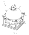
- FIG 4 is a perspective view of an inertial measurement unit (IMU) 400 according to one embodiment for use in an inertial navigation system.
- the IMU 400 can be implemented with a wireless power transfer transformer as discussed previously.
- the IMU 400 includes a stationary outer case assembly 401 with an upper gas plenum 402 and a lower gas plenum 404.
- the upper and lower gas plenums surround upper and lower support shells, which in turn surround a spherical sensor assembly in the interior of IMU 400.
- the gas plenums and support shells are secured to upper and lower surfaces of a mounting plate 406.
- the lower gas plenum 404 is set in a stationary support frame 410, which can be attached to mounting plate 406 by a set of fasteners 412 located at each corner of mounting plate 406.
- a monitoring device 420 can be placed on top of upper gas plenum 102 to monitor the rotation and position of the sensor assembly.
- the power transfer gap control approach disclosed herein provides power to the sensor assembly by maintaining a narrow gap to allow relative motion between the transmitting core and the receiving core without physical contact. This provides the ability to reposition the sensor assembly in the IMU without creating mechanical wear and therefore increases reliability and product life. By providing a minimal narrow gap between the transmitting core and the receiving core, the efficiency of the power transfer is increased.
Landscapes
- Engineering & Computer Science (AREA)
- Radar, Positioning & Navigation (AREA)
- Remote Sensing (AREA)
- Physics & Mathematics (AREA)
- General Physics & Mathematics (AREA)
- Automation & Control Theory (AREA)
- Computer Networks & Wireless Communication (AREA)
- Power Engineering (AREA)
- Gyroscopes (AREA)
- Arrangements For Transmission Of Measured Signals (AREA)
Abstract
Description
- This application is related to commonly assigned
U.S. Patent Application Serial No. 11/004,184, filed on December 3, 2004 , entitled "GAS SUPPORTED INERTIAL SENSOR SYSTEM AND METHOD" which is incorporated herein by reference. - This application is also related to commonly assigned
U.S. Patent Application Serial No. 11/622,226, filed on January 11, 2007 - This application is also related to commonly assigned U.S. Patent Application Serial No. (Honeywell Docket No. H0014141), filed on even date herewith, entitled "INERTIAL MEASUREMENT UNIT WITH GAS PLENUMS" which is incorporated herein by reference.
- Precision inertial navigation systems are used in civil and military aviation, missiles and other projectiles, submarines and other underwater vehicles, space exploration technology, as well as in numerous other vehicle applications. A typical inertial navigation system (INS) measures the position and attitude of a vehicle by measuring the accelerations and rotations applied to the vehicle's inertial frame of reference. Since the typical INS is not dependent on other points of reference, it is resistant to jamming and deception.
- An INS usually includes an inertial measurement unit (IMU) combined with control mechanisms, allowing the path of a vehicle to be controlled according to the position determined by the INS. An IMU contains instruments for position monitoring. A conventional INS requires concentric sets of ball bearing supported gimbals that allow instruments to freely rotate in vehicle maneuvers and further allow for manipulation during a calibration routine.
- An INS typically uses either gyrostablized platforms or 'strapdown' systems. The gyrostabilized system allows a vehicle's roll, pitch and yaw angles to be measured directly at the bearings of the gimbals. The INS is traditionally rotated using electromagnetic motors on a ball bearing supported gimbal axis. Disadvantages of this scheme is that it employs multiple expensive precision mechanical parts including moving parts that can wear out or jam, and is vulnerable to gimbal lock. In addition, for each degree of freedom, another gimbal is required thus increasing the size and complexity of the INS. Therefore, to get complete three dimensional calibration, at least three gimbals are needed.
- A typical inertial sensor assembly (ISA) within the INS is an electronic device that contains internally embedded instrumentation (e.g., one or more accelerometers and gyroscopes) that communicates with other vehicle systems. Data from the internally embedded instrumentation is typically communicated to the other vehicle systems through moving contact devices, such as slip rings or twist caps. The slip rings and twist caps provide a constant communication link for the data without restricting the movement of the ISA.
- However, the slip rings and twist caps (along with the ball bearing supported gimbals) are moving physical structures subject to wear. Multiple slip rings and twist caps represent potential failure points for the typical INS. Similarly, transferring supply power to the ISA through the multiple slip rings and twist caps is subject to interference due to electrical noise. Moreover, receiving the supply power through the moving contact devices is restricted in applications where the gimbals are absent and physical contact with the ISA is prohibited.
- The present invention is directed to an inertial measurement unit that comprises an outer case assembly including an upper gas plenum and a lower gas plenum. An upper support shell is surrounded by the upper gas plenum, with the upper support shell having a plurality of apertures. A lower support shell is surrounded by the lower gas plenum, with the lower support shell having a plurality of apertures. A sensor assembly includes a sensor shell having an outer surface, with the sensor assembly surrounded by the upper and lower support shells. A plurality of gas bearing pads extends through the apertures in the upper and lower support shells. The plurality of gas bearing pads are configured to receive a first pressurized gas from the upper and lower gas plenums and inject the first pressurized gas into a gap that separates the gas bearing pads and the sensor shell. This produces a first gas bearing that allows the sensor assembly to be freely suspended and rotated in all directions. The inertial measurement unit also comprises at least one wireless power transfer transformer that includes a power transmitting core mounted to the outer case assembly, and a power receiving core mounted in an opening of the sensor shell. The power receiving core is configured to be aligned with the power transmitting core for wireless power transfer. The power transmitting core is configured to inject a second pressurized gas into a gap between the power transmitting core and the power receiving core. This produces a second gas bearing that maintains a predetermined separation distance between the power transmitting core and the power receiving core during the wireless power transfer.
- Features of the present invention will become apparent to those skilled in the art from the following description with reference to the drawings. Understanding that the drawings depict only typical embodiments of the invention and are not therefore to be considered limiting in scope, the invention will be described with additional specificity and detail through the use of the accompanying drawings, in which:
-
Figure 1 is a cut away side view of an outer case assembly for an inertial measurement unit according to one embodiment; -
Figure 2 is a cut away side view of a sensor assembly for an inertial measurement unit having a wireless power transfer transformer; -
Figure 3 is an exploded perspective view of a wireless power transfer transformer for use in an inertial measurement unit; and -
Figure 4 is a perspective view of an inertial measurement unit that can utilize a wireless power transfer transformer. - In the following detailed description, embodiments are described in sufficient detail to enable those skilled in the art to practice the invention. It should be understood that other embodiments may be utilized without departing from the scope of the present invention. The following detailed description is, therefore, not to be taken in a limiting sense.
- The present invention is related to an inertial measurement unit (IMU) with wireless power transfer gap control. An internal sensor assembly in the IMU is configured to rotate for self calibration. Power needs to be transmitted to the sensor assembly without limiting its rotational freedom and without a mechanical wear out mechanism. This is accomplished with a wireless power transfer transformer to induce a power transfer across a small gap. The smaller the gap, the higher the efficiency of the power transfer. This invention minimizes the gap by utilizing pressurized gas to act as a gas bearing between a pair of power transfer cores.
- A method for wireless power transfer in an inertial measurement unit according to the invention generally comprises aligning a power receiving core in a sensor assembly with a power transmitting core external to the sensor assembly. A pressurized gas is injected through the power transmitting core into a controlled gap between the power transmitting core and the power receiving core to produce a gas bearing. A wireless power signal is then transmitted from the power transmitting core to the power receiving core.
- By creating a small film of high pressure gas between the power transmitting core, which can be mounted to a vehicle casing, and the power receiving core located on the rotating IMU, the gap is held to a very small distance by the film of gas acting as a bearing. Gas bearings have very stiff spring rates and operate with increased stiffness as the gap is decreased. The transmitting core has a spring loaded mounting stem that preloads the transmitting core toward the receiving core with the gas bearing opposing that spring force. This provides geometric alignment between the two cores and minimizes the gap with little if any need for manual adjustment.
- While the present invention is particularly useful in a precision inertial guidance system such as used in strategic missiles, other industrial air bearing or rotating element applications may also find use for the present gas bearing gap, such as to control the critical spacing of a wireless inductive power transfer system.
- Further details of the present invention are discussed as follows with respect to the drawings.
-
Figure 1 is a cutaway view of a stationaryouter case assembly 100 for an IMU according to one embodiment. Theouter case assembly 100 includes anupper gas plenum 102 and alower gas plenum 104. Theupper gas plenum 102 comprises anupper side portion 106 having a first thickness and anupper rim portion 108 having a second thickness that is greater than the first thickness ofside portion 106. Likewise, thelower gas plenum 104 comprises alower side portion 110 having a first thickness and alower rim portion 112 having a second thickness that is greater than the first thickness ofside portion 110. Theside portion 106 ofupper gas plenum 102 gradually tapers in thickness torim portion 108 that is adjacent to the top ofouter case assembly 100. Likewise,side portion 110 oflower gas plenum 104 also gradually tapers in thickness torim portion 112 that is adjacent to the bottom ofouter case assembly 100. - The
thicker rim portions outer case assembly 100 are configured to handle the stress of high pressure gas in the plenums. Therim portions lower gas outlets outer case assembly 100. The upper andlower gas plenums respective plenum flanges gas plenums outer case assembly 100. Such radiation shielding is described in further detail in copending U.S. Application Serial No. (Honeywell Docket No. H0014141). - An
upper support shell 120 is surrounded byupper gas plenum 102 and has a plurality ofapertures 121. Alower support shell 122 is surrounded bylower gas plenum 104 and has a plurality ofapertures 123. The upper andlower support shells respective shell flanges plate 128 on upper and lower surfaces thereof. The plenum flanges 117, 118 are respectively attached to shellflanges - The upper and
lower support shells respective lip portions rim portions outer case assembly 100. Thelip portions bottom openings lower gas outlets - The
support shells gas bearing pads 140 throughapertures gas bearing pads 140 have hollow stems 142 that extend throughapertures gas bearing pads 140 are adapted to be received into threaded apertures insupport shells - An
upper gas chamber 144 is formed betweenupper gas plenum 102 and the outer surface ofupper support shell 120. Alower gas chamber 146 is formed betweenlower gas plenum 104 and the outer surface oflower support shell 122. Thegas chambers outer case assembly 100. - An upper gas inlet is provided in mounting
plate 128 and is in communication withupper gas chamber 144. Ajet nozzle 150 is coupled to the upper gas inlet. Similarly, a lower gas inlet is also provided in mountingplate 128 and is in communication withlower gas chamber 146. A jet nozzle is also coupled to the lower gas inlet. High pressure gas, such as air or nitrogen, can be directed through the jet nozzles into the gas inlets and passes into the high pressure zones ofgas chambers gas bearing pads 140. - A
sensor shell 160 for a sensor assembly is surrounded by the upper andlower support shells Figure 1 ,sensor shell 160 includesinternal fastening structures 162 that are configured to secure embedded instrumentation (not shown) within the sensor assembly, such as gyroscopes, accelerometers, and the like. Thesensor shell 160 can have an outer surface with a substantially spherical shape such that the sensor assembly is in the form of a ball. Thesensor shell 160 can be made from a metallic material such as aluminum. - As shown in
Figure 1 , upper andlower support shells lower gas plenums - The upper and
lower support shells sensor shell 160 to allow for mounting ofgas bearing pads 140. Thegas bearing pads 140 and the outer spherical surface ofsensor shell 160 are separated by anarrow gap 164 when pressurized gas is fed through the gas bearing pads. This creates a gas bearing that allowssensor shell 160 to be freely suspended and rotated in all directions. - A first
pressure relief valve 170 is coupled toupper gas plenum 102 atflange 117 adjacent tojet nozzle 150. A secondpressure relief valve 172 is coupled tolower gas plenum 104 atflange 118 also adjacent tojet nozzle 150. Theflanges jet nozzle 150 definerespective ports gas chambers valves ports gas chambers - An O-
ring 180 is disposed in a slot that circumscribesshell flange 124, and an O-ring 182 is disposed in a slot that circumscribesshell flange 126. The O-rings shell flanges plenum flanges ring 184 is disposed in a slot on a surface oflip portion 130 ofupper support shell 120 to provide a fluid-tight joint betweenlip portion 130 andrim portion 108 ofgas plenum 102. An O-ring 186 is disposed in a slot on a surface oflip portion 132 oflower support shell 122 to provide a fluid-tight joint betweenlip portion 132 andrim portion 112 ofgas plenum 104. - A wireless
power transfer transformer 210 is disposed in a high pressure gas inlet of mountingplate 128. Thetransformer 210 has apower transmitting core 212 including a hollow mounting stem 220 coupled to a spring cushion joint 222 and angas pad 224. Thetransformer 210 also has a power receiving core (not shown). A hose can be coupled to stem 220 to provide pressurized gas to power transmittingcore 212. Further details with respect totransformer 210 are discussed hereafter. -
Figure 2 is a cut away view of asensor assembly 200 that has embedded instrumentation in aspherical sensor shell 201. Thesensor assembly 200 can be implemented within theouter case assembly 100 of an IMU as shown inFigure 1 . The embedded instrumentation withinsensor assembly 200 can include one ormore gyroscopes 202, one ormore accelerometers 204, a rechargeable power source such as one ormore batteries 206, as well as other electronic components such as a processor. The gyroscopes sense rotation in any of three axes, and the accelerometers measure acceleration in any of three directions. Anaxle 207 is disposed in the middle ofsensor assembly 200 and has twoeccentric weights axle 208 provides an external balance mechanism forsensor assembly 200. - The
sensor assembly 200 is configured to communicate sensor data from the embedded instrumentation to a controller or processor for the IMU. The sensor data can include data collected from outputs of the embedded instrumentation, system health indicators and alarms (e.g., battery power level and component failure indications), and programming and control instructions for electronic components within the embedded instrumentation. Thesensor assembly 200 can measure the position and attitude of a vehicle in which it is mounted by measuring the accelerations and rotations applied to the vehicle's inertial frame. For example, ifsensor shell 201 rotates, the gyroscopes sense motion and transmit sensor data to the processor. Ifsensor shell 201 translates or moves, the accelerometers sense velocity/acceleration and send sensor data to the processor. The processor can calculate the position of the sensor shell and the direction it is pointed at any given time anywhere in space. - As discussed above, the wireless
power transfer transformer 210 haspower transmitting core 212, which includes hollow mounting stem 220 coupled to spring cushion joint 222 andgas pad 224. As shown inFigure 2 ,transformer 210 also includes apower receiving core 214 that is mounted in an opening ofsensor shell 201, such that the outer surface ofpower receiving core 214 is flush with the outer surface ofsensor shell 201. - The
power receiving core 214 is configured to be aligned withpower transmitting core 212 for wireless power transfer in order to chargebatteries 206. While only a single wirelesspower transfer transformer 210 is shown inFigures 1 and2 , it should be understood that one or more additional wireless power transfer transformers can be implemented in different locations aroundsensor assembly 200 as desired. - The receiving
core 214 is coupled to chargingcoil electronics 226 insensor assembly 200. The transmittingcore 212 and receivingcore 214 are separated by anarrow gap 230 that is maintained by high pressure gas supplied through mountingstem 220. The high pressure gas provides a gas bearing to keep transmittingcore 212 and receivingcore 214 separated. The nature of gas bearings is to have a small but firm gap between the two halves of the bearing. The present implementation creates the gas bearing with transmittingcore 212 and receivingcore 214 as the two halves of the bearing. The spring cushion joint 222 placed behind the transmittingcore 212 allows for self adjustment of transmittingcore 212 relative to receivingcore 214 to account for tolerance and to continuously optimizegap 230 at all attitudes of the IMU. - During operation of an IMU having
outer case assembly 100 andsensor assembly 200, pressurized gas is directed through the jet nozzles and is distributed in the high pressure zones ofgas chambers pads 140 from the gas chambers to provide a high pressure gas bearing between bearingpads 140 and the outer surface of sensor shell 160 (201). The gas bearing allows the sensor shell to rotate freely in a near frictionless environment, which provides for easy calibration of sensors in the sensor shell. - When
batteries 206 insidesensor assembly 200 require additional electrical charge, a controller aligns receivingcore 214 with transmittingcore 212 to transfer wireless power signals from a power supply connected to the transmitting core. The bearingpads 140 keepsensor assembly 200 suspended to allow for rotation and alignment of receivingcore 214 with transmittingcore 212. Once aligned, transmittingcore 212 and receivingcore 214 are separated by the controlled gap having a gas bearing to complete the wireless power transfer. In an exemplary implementation, the controlled gap can provide a separation distance of about 0.001 inch (0.0254 mm) or less between the transmitting core and the receiving core. The separation distance of the gap is maintained at a precise value by the gas bearing created by the transmitting core, providing for efficient power transfer. -
Figure 3 is an exploded perspective view of a wirelesspower transfer transformer 310 according to one embodiment. Thetransformer 310 can be implemented in an IMU and sensor assembly such as described previously fortransformer 210. Thetransformer 310 includes a casing mountablepower transmitting core 312, and apower receiving core 314 that is mountable in a sensor assembly. The transmittingcore 312 and receivingcore 314 are configured to face each other during a power transfer and are separated by a controlledgap 316. - The transmitting
core 312 has a hollow mounting stem 320 defining a plenum that supplies high pressure gas. Thestem 320 has aninlet 324 and anoutlet 326. An elastomeric joint 328 having an opening therethrough is configured to coveroutlet 326. The elastomeric joint 328 provides a spring cushion that allows for self alignment, axial motion, and radial adjustment of transmittingcore 312 to adjust the controlledgap 316 based on gas pressure. Agas pad 330 is configured to mate with elastomeric joint 328 and stem 320 throughreceptacle 332. Thegas pad 330 has a central hole for directing high pressure gas to controlledgap 316 to form a gas bearing therein. The gas flow path through transmittingcore 312 is shown by the arrow G. Thegas pad 330 has anouter surface 334 with acircular groove 336 for holding a single coil winding 338. The transmittingcore 312 is configured to be electrically coupled to externalcharging coil electronics 340. - The receiving
core 314 has anouter surface 342 that facesouter surface 334 ofgas pad 330. In one implementation,outer surface 334 ofgas pad 330 has a substantially spherical concave shape, andouter surface 342 of receivingcore 314 has a corresponding substantially spherical convex shape to allow controlledgap 316 to be as uniform as possible. The spherical convex shape ofouter surface 342 is configured to match the outer curvature of a spherical sensor shell that utilizestransformer 310. The pressurized gas, the elastomeric joint, and the core curvatures all work in conjunction to provide a stationary, controlledgap 316. - The
outer surface 342 of receivingcore 314 is configured to hold a single coil winding 344 that faces coil winding 338 ofgas pad 330. The receivingcore 314 is configured to be electrically coupled to internalcharging coil electronics 346. Thesingle coil windings -
Figure 4 is a perspective view of an inertial measurement unit (IMU) 400 according to one embodiment for use in an inertial navigation system. TheIMU 400 can be implemented with a wireless power transfer transformer as discussed previously. TheIMU 400 includes a stationaryouter case assembly 401 with anupper gas plenum 402 and alower gas plenum 404. The upper and lower gas plenums surround upper and lower support shells, which in turn surround a spherical sensor assembly in the interior ofIMU 400. The gas plenums and support shells are secured to upper and lower surfaces of a mountingplate 406. Thelower gas plenum 404 is set in astationary support frame 410, which can be attached to mountingplate 406 by a set offasteners 412 located at each corner of mountingplate 406. Amonitoring device 420 can be placed on top ofupper gas plenum 102 to monitor the rotation and position of the sensor assembly. - The power transfer gap control approach disclosed herein provides power to the sensor assembly by maintaining a narrow gap to allow relative motion between the transmitting core and the receiving core without physical contact. This provides the ability to reposition the sensor assembly in the IMU without creating mechanical wear and therefore increases reliability and product life. By providing a minimal narrow gap between the transmitting core and the receiving core, the efficiency of the power transfer is increased.
- The present invention may be embodied in other specific forms without departing from its essential characteristics. The described embodiments are to be considered in all respects only as illustrative and not restrictive. The scope of the invention is therefore indicated by the appended claims rather than by the foregoing description. All changes that come within the meaning and range of equivalency of the claims are to be embraced within their scope.
Claims (10)
Applications Claiming Priority (1)
| Application Number | Priority Date | Filing Date | Title |
|---|---|---|---|
| US11/778,970 US7425097B1 (en) | 2007-07-17 | 2007-07-17 | Inertial measurement unit with wireless power transfer gap control |
Publications (2)
| Publication Number | Publication Date |
|---|---|
| EP2019289A2 true EP2019289A2 (en) | 2009-01-28 |
| EP2019289A3 EP2019289A3 (en) | 2014-07-16 |
Family
ID=39743192
Family Applications (1)
| Application Number | Title | Priority Date | Filing Date |
|---|---|---|---|
| EP08160119.7A Withdrawn EP2019289A3 (en) | 2007-07-17 | 2008-07-10 | Intertial measurement unit with wireless power transfer gap control |
Country Status (2)
| Country | Link |
|---|---|
| US (1) | US7425097B1 (en) |
| EP (1) | EP2019289A3 (en) |
Cited By (1)
| Publication number | Priority date | Publication date | Assignee | Title |
|---|---|---|---|---|
| FR3036474A1 (en) * | 2015-05-22 | 2016-11-25 | Thales Sa | INERTIAL POWER PLANT COMPRISING AN EXTERNAL HOUSING AND A SUSPENDED INERTIAL SENSOR ASSEMBLY |
Families Citing this family (10)
| Publication number | Priority date | Publication date | Assignee | Title |
|---|---|---|---|---|
| US8351046B2 (en) * | 2008-09-29 | 2013-01-08 | The Boeing Company | Multiple nested interferometric fiber optic gyroscope system |
| US8145420B2 (en) * | 2008-12-11 | 2012-03-27 | Honeywell International Inc. | Method and apparatus for joining together portions of a geometric assembly |
| CN101922938B (en) * | 2010-07-14 | 2012-06-06 | 北京航空航天大学 | High-precision laser gyroscope inertia measurement system for POS |
| US8706058B2 (en) | 2011-03-24 | 2014-04-22 | Honeywell International Inc. | RF data transfer in a spherical cavity |
| US9140763B2 (en) * | 2011-09-19 | 2015-09-22 | Utah State University | Wireless power transfer test system |
| USD813761S1 (en) * | 2015-07-29 | 2018-03-27 | Lr Acquisition, Llc | Controller of an unmanned aerial vehicle |
| US10262516B2 (en) * | 2016-06-01 | 2019-04-16 | Green Power Monitoring Systems, Inc. | Integrated hanger bearing monitor |
| US10323687B2 (en) * | 2016-09-07 | 2019-06-18 | New Way Machine Components, Inc. | Snap joint for externally pressurized gas bearings |
| CN119209952B (en) * | 2024-10-12 | 2025-06-06 | 青岛科技大学 | Bipolar arched magnetic coupling structure for underwater wireless energy transmission and its application |
| CN119935111B (en) * | 2024-12-23 | 2025-11-07 | 北京航天控制仪器研究所 | Novel wireless transmission inertial measurement device |
Family Cites Families (78)
| Publication number | Priority date | Publication date | Assignee | Title |
|---|---|---|---|---|
| US1315735A (en) | 1919-09-09 | Don michell | ||
| US2363260A (en) | 1941-10-10 | 1944-11-21 | American Steel & Wire Co | Bearing for rope stranding machines |
| US2710234A (en) | 1950-05-22 | 1955-06-07 | Hughes Aircraft Co | Fluid-bearing mount |
| US2999391A (en) | 1950-12-11 | 1961-09-12 | North American Aviation Inc | Self-compensating gyro apparatus |
| GB866473A (en) | 1956-08-24 | 1961-04-26 | English Electric Co Ltd | Improvements in or relating to stabilized platform systems for vehicles |
| GB878939A (en) | 1957-02-07 | 1961-10-04 | Sperry Gyroscope Co Ltd | Balance adjustment of suspended bodies |
| US3039316A (en) | 1957-10-25 | 1962-06-19 | North American Aviation Inc | Guidance system utilizing two-axis stabilization |
| US3056303A (en) | 1958-08-29 | 1962-10-02 | Thompson Ramo Wooldridge Inc | Hydraulically and spherically supported inertial reference |
| US2959060A (en) | 1959-08-17 | 1960-11-08 | Honeywell Regulator Co | Control apparatus |
| GB1015681A (en) | 1961-05-26 | 1966-01-05 | Honeywell Inc | Improvements in or relating to the static balancing of rotatable elements |
| US3258977A (en) | 1963-01-04 | 1966-07-05 | Gen Precision Inc | Gyro drift limiting system |
| US3269195A (en) | 1964-04-03 | 1966-08-30 | North American Aviation Inc | Acceleration and rate control for gyro case rotation |
| US3365942A (en) | 1964-04-03 | 1968-01-30 | Sperry Rand Corp | Inertial altimeter |
| US3328595A (en) | 1964-08-24 | 1967-06-27 | Jr Marion N Todd | Dual beam optical gyroscope pickoff |
| US3439546A (en) | 1965-10-24 | 1969-04-22 | Northrop Corp | Floated inertial platform |
| US3596523A (en) * | 1967-12-04 | 1971-08-03 | Whittaker Corp | Full-freedom gimballess gyroscope system |
| US3572856A (en) | 1968-09-27 | 1971-03-30 | Gen Electric | Apparatus for producing small displacements |
| US3576124A (en) | 1969-03-19 | 1971-04-27 | Bendix Corp | System and method for aligning an inertial navigation system |
| US3769710A (en) | 1969-04-01 | 1973-11-06 | R Reister | Electronic celestial navigation means |
| US3670585A (en) | 1970-04-17 | 1972-06-20 | Northrop Corp | Attitude readout for floated inertial platform |
| US3938256A (en) | 1970-09-17 | 1976-02-17 | General Electric Company | Quick settling gyrocompass having interaxis decoupling compensation for improved response time |
| GB1284195A (en) | 1970-12-04 | 1972-08-02 | Singer Co | Means for dynamically balancing a gyroscope |
| US3782167A (en) | 1971-11-05 | 1974-01-01 | Westinghouse Electric Corp | Onboard calibration and test of airborne inertial devices |
| US4003265A (en) | 1975-07-09 | 1977-01-18 | Litton Systems, Inc. | Mass balancing system for rotatable assemblies |
| US4143466A (en) | 1977-03-09 | 1979-03-13 | Sperry Rand Corporation | Free floating gyroscopic compass azimuth pick-off and rotor drive system |
| US4150579A (en) | 1977-04-11 | 1979-04-24 | Northrop Corporation | Hydraulic torquer device for floated inertial platform |
| JPS5544134A (en) | 1978-09-22 | 1980-03-28 | Hitachi Ltd | Guide bearing |
| US4214482A (en) | 1979-04-02 | 1980-07-29 | Northrop Corporation | Inertial instrument |
| US4290316A (en) * | 1979-06-13 | 1981-09-22 | Rockwell International Corporation | Free-rotor gas-bearing gyroscope having electromagnetic rotor restraint and acceleration output signal |
| US4244215A (en) | 1979-09-24 | 1981-01-13 | Nasa | Autonomous navigation system |
| FR2506007A1 (en) | 1981-05-18 | 1982-11-19 | Telecommunications Sa | DEVICE FOR MEASURING COORDINATES OF A ROTATING SPHERE AND METHOD FOR MANUFACTURING A PART OF SAID DEVICE |
| US4413864A (en) | 1981-07-31 | 1983-11-08 | Optimetrix Corporation | Gas bearing |
| US4458426A (en) | 1982-03-25 | 1984-07-10 | The Bendix Corporation | Gyroscopic apparatus |
| US4671650A (en) | 1982-09-20 | 1987-06-09 | Crane Co. (Hydro-Aire Division) | Apparatus and method for determining aircraft position and velocity |
| US4515486A (en) | 1984-02-03 | 1985-05-07 | Ide Russell D | Elastomeric supported hydrodynamic bearing |
| US4822181A (en) | 1984-04-02 | 1989-04-18 | Honeywell Inc. | Hydrostatic support device and method |
| CH665715A5 (en) | 1984-11-08 | 1988-05-31 | Wild Heerbrugg Ag | METHOD AND DEVICE FOR MEASURING THE ANGLE STORAGE OF AN OBJECT PROVIDED WITH A TARGET BRAND. |
| US4723735A (en) | 1984-12-28 | 1988-02-09 | The Charles Stark Draper Laboratory, Inc. | Energy storage attitude control and reference system |
| US4711125A (en) | 1985-11-06 | 1987-12-08 | Morrison Melvin M | Inertial measurement unit |
| US5743654A (en) | 1987-05-29 | 1998-04-28 | Kmc, Inc. | Hydrostatic and active control movable pad bearing |
| DE3807725A1 (en) | 1988-03-09 | 1989-09-21 | Bodenseewerk Geraetetech | END PHASE STEERED BULLET |
| US5099430A (en) | 1988-10-28 | 1992-03-24 | Joseph Hirsch | Method and apparatus for continuously suppressing unwanted rotational phenomena in a rotating body |
| US5396326A (en) | 1989-04-03 | 1995-03-07 | Northrop Grumman Corporation | Two gimbal error averaging astro-inertial navigator |
| US5067084A (en) | 1989-05-25 | 1991-11-19 | Honeywell Inc. | Inertial measurement unit with aiding from roll isolated gyro |
| DE3927920A1 (en) | 1989-08-24 | 1991-02-28 | Bodenseewerk Geraetetech | METHOD FOR ELIMINATING GYRO ERRORS |
| US5088825A (en) | 1989-12-27 | 1992-02-18 | Honeywell Inc. | Housing and support assembly for ring laser gyroscope |
| US5357437A (en) | 1992-07-01 | 1994-10-18 | Westinghouse Electric Corporation | Magnetic marker position fixing system for underwater vehicles |
| US5410232A (en) | 1992-12-18 | 1995-04-25 | Georgia Tech Research Corporation | Spherical motor and method |
| US5319577A (en) | 1992-12-18 | 1994-06-07 | Georgia Tech Research Corporation | Orientation sensing system and method for a spherical body |
| DK137293D0 (en) | 1993-12-08 | 1993-12-08 | Danfoss As | RADIAL SLIDE BEARING WITH SLIDE SHOES AND SLIDE SHOES FOR A RADIAL SLIDE BEARING |
| DE4410709A1 (en) | 1994-03-28 | 1995-10-05 | Bodenseewerk Geraetetech | Monitoring device for monitoring the flight safety of aircraft |
| US6172665B1 (en) | 1994-11-14 | 2001-01-09 | Edward T. Bullister | Mouse and trackball with optimal measurement optics |
| US5790049A (en) | 1996-02-20 | 1998-08-04 | Raytheon Company | Two axis gimbal suspension with wireless signal and power transfer |
| US5894323A (en) | 1996-03-22 | 1999-04-13 | Tasc, Inc, | Airborne imaging system using global positioning system (GPS) and inertial measurement unit (IMU) data |
| US6032546A (en) * | 1997-07-21 | 2000-03-07 | Stone; Neil | System for transferring electrical power between non-contacting elements in relative motion |
| US6145393A (en) | 1998-11-27 | 2000-11-14 | Canton; Dino | Floated gimbal optical platform |
| EP1061338A1 (en) * | 1999-06-18 | 2000-12-20 | EMT Ingenieurbüro für Elektro-Mechanische Technologien Dipl.-Ing. Hartmut Euer mbH | Device for directional stabilisation of sensors in vehicles |
| DE19940103A1 (en) | 1999-08-24 | 2001-03-01 | Zeiss Carl Fa | Fluid pressure bearing |
| US6594623B1 (en) | 1999-11-12 | 2003-07-15 | Cognex Technology And Investment Corporation | Determining three-dimensional orientation of objects |
| AUPQ835100A0 (en) | 2000-06-23 | 2000-07-20 | Bishop Innovation Limited | Position sensor |
| CA2364919A1 (en) | 2000-12-14 | 2002-06-14 | Kevin Tuer | Proprioceptive golf club with analysis, correction and control capabilities |
| US6481672B1 (en) | 2001-01-18 | 2002-11-19 | Lockheed Martin Corporation | Gimbaled thruster control system |
| US6802221B2 (en) | 2001-03-29 | 2004-10-12 | General Electric Company | System and method for conditioned-based monitoring of a bearing assembly |
| FR2824393B1 (en) | 2001-05-03 | 2003-07-25 | Sagem | LONG-TERM NAVIGATION METHOD AND DEVICE |
| US7066653B2 (en) | 2001-10-03 | 2006-06-27 | Dresser-Rand Company | Bearing assembly and method |
| US6711952B2 (en) | 2001-10-05 | 2004-03-30 | General Electric Company | Method and system for monitoring bearings |
| GB2380793B (en) | 2001-10-10 | 2005-03-09 | Roke Manor Research | Positioning system |
| US20030120425A1 (en) | 2001-12-26 | 2003-06-26 | Kevin Stanley | Self-correcting wireless inertial navigation system and method |
| FR2835059B1 (en) | 2002-01-18 | 2004-04-09 | Richard Kirby | SYSTEM FOR DETERMINING THE SPEED OF A SKI |
| US6826478B2 (en) | 2002-04-12 | 2004-11-30 | Ensco, Inc. | Inertial navigation system for mobile objects with constraints |
| WO2004023150A1 (en) | 2002-09-03 | 2004-03-18 | Loughborough University Enterprises Limited | Marking of objects for speed and spin measurements |
| US7032469B2 (en) | 2002-11-12 | 2006-04-25 | Raytheon Company | Three axes line-of-sight transducer |
| US6786084B2 (en) | 2003-01-13 | 2004-09-07 | Delphi Technologies, Inc. | Sensor assembly and method for non-intrusively sensing instantaneous speed of the engine of a vehicle |
| US20040212803A1 (en) | 2003-04-22 | 2004-10-28 | Sultex Ag | Measuring device for movements on a weaving machine |
| US6918186B2 (en) | 2003-08-01 | 2005-07-19 | The Charles Stark Draper Laboratory, Inc. | Compact navigation system and method |
| US7003399B1 (en) * | 2004-09-10 | 2006-02-21 | Honeywell International Inc. | Gas jet control for inertial measurement unit |
| US7698064B2 (en) | 2004-09-10 | 2010-04-13 | Honeywell International Inc. | Gas supported inertial sensor system and method |
| US7340344B2 (en) * | 2004-09-10 | 2008-03-04 | Honeywell International Inc. | Spherical position monitoring system |
-
2007
- 2007-07-17 US US11/778,970 patent/US7425097B1/en active Active
-
2008
- 2008-07-10 EP EP08160119.7A patent/EP2019289A3/en not_active Withdrawn
Cited By (1)
| Publication number | Priority date | Publication date | Assignee | Title |
|---|---|---|---|---|
| FR3036474A1 (en) * | 2015-05-22 | 2016-11-25 | Thales Sa | INERTIAL POWER PLANT COMPRISING AN EXTERNAL HOUSING AND A SUSPENDED INERTIAL SENSOR ASSEMBLY |
Also Published As
| Publication number | Publication date |
|---|---|
| US7425097B1 (en) | 2008-09-16 |
| EP2019289A3 (en) | 2014-07-16 |
Similar Documents
| Publication | Publication Date | Title |
|---|---|---|
| US7425097B1 (en) | Inertial measurement unit with wireless power transfer gap control | |
| US7647176B2 (en) | Method and system for wireless power transfers through multiple ports | |
| US7762133B2 (en) | Inertial measurement unit with gas plenums | |
| US5897223A (en) | Stabilized platform system for camera | |
| Kim et al. | Automatic mass balancing of air-bearing-based three-axis rotational spacecraft simulator | |
| US12298138B1 (en) | Enhanced performance inertial measurement unit (IMU) system and method for error, offset, or drift correction or prevention | |
| US11692828B1 (en) | Multi-IMU guidance measurement and control system with handshake capability to refine guidance control in response to changing conditions | |
| EP2028440A2 (en) | Disc resonator integral inertial measurement unit. | |
| EP3203183B1 (en) | Conduction cooled autonomous gimbaled inertial measurement unit | |
| US20110167893A1 (en) | Method and apparatus for in-flight calibration of gyroscope using magnetometer reference | |
| US6501203B2 (en) | Vibration control apparatus | |
| CN109597133B (en) | Apparatus and method for vector component data acquisition | |
| CN101561281A (en) | Working method of strap-down magnetic inertia combination system | |
| US20060070443A1 (en) | Magnetofluidic accelerometer with capacitive sensing of inertial body position | |
| US7698064B2 (en) | Gas supported inertial sensor system and method | |
| US7003399B1 (en) | Gas jet control for inertial measurement unit | |
| US8145420B2 (en) | Method and apparatus for joining together portions of a geometric assembly | |
| US20060058960A1 (en) | RF wireless communication for deeply embedded aerospace systems | |
| US20060054660A1 (en) | Articulated gas bearing support pads | |
| US9891341B2 (en) | Gravity gradiometer system with spherical air bearing based platform | |
| US7289902B2 (en) | Three dimensional balance assembly | |
| WO2006060601A1 (en) | Three dimensional balance assembly | |
| Veremeenko et al. | Small-sized integrated navigation system | |
| Angus et al. | The guidance system for Ariane | |
| Power | Closed-loop depth and attitude control of an underwater relerobotic vehicle |
Legal Events
| Date | Code | Title | Description |
|---|---|---|---|
| PUAI | Public reference made under article 153(3) epc to a published international application that has entered the european phase |
Free format text: ORIGINAL CODE: 0009012 |
|
| 17P | Request for examination filed |
Effective date: 20080710 |
|
| AK | Designated contracting states |
Kind code of ref document: A2 Designated state(s): AT BE BG CH CY CZ DE DK EE ES FI FR GB GR HR HU IE IS IT LI LT LU LV MC MT NL NO PL PT RO SE SI SK TR |
|
| AX | Request for extension of the european patent |
Extension state: AL BA MK RS |
|
| PUAL | Search report despatched |
Free format text: ORIGINAL CODE: 0009013 |
|
| AK | Designated contracting states |
Kind code of ref document: A3 Designated state(s): AT BE BG CH CY CZ DE DK EE ES FI FR GB GR HR HU IE IS IT LI LT LU LV MC MT NL NO PL PT RO SE SI SK TR |
|
| AX | Request for extension of the european patent |
Extension state: AL BA MK RS |
|
| RIC1 | Information provided on ipc code assigned before grant |
Ipc: H02J 7/02 20060101ALI20140611BHEP Ipc: G01C 21/16 20060101AFI20140611BHEP Ipc: G01C 19/16 20060101ALI20140611BHEP Ipc: G01C 19/20 20060101ALI20140611BHEP |
|
| 17Q | First examination report despatched |
Effective date: 20140709 |
|
| AKX | Designation fees paid |
Designated state(s): DE FR GB |
|
| AXX | Extension fees paid |
Extension state: BA Extension state: MK Extension state: AL Extension state: RS |
|
| RAP1 | Party data changed (applicant data changed or rights of an application transferred) |
Owner name: HONEYWELL INTERNATIONAL INC. |
|
| STAA | Information on the status of an ep patent application or granted ep patent |
Free format text: STATUS: THE APPLICATION IS DEEMED TO BE WITHDRAWN |
|
| 18D | Application deemed to be withdrawn |
Effective date: 20160202 |