EP2019270A1 - Refrigeration system - Google Patents
Refrigeration system Download PDFInfo
- Publication number
- EP2019270A1 EP2019270A1 EP07743280A EP07743280A EP2019270A1 EP 2019270 A1 EP2019270 A1 EP 2019270A1 EP 07743280 A EP07743280 A EP 07743280A EP 07743280 A EP07743280 A EP 07743280A EP 2019270 A1 EP2019270 A1 EP 2019270A1
- Authority
- EP
- European Patent Office
- Prior art keywords
- refrigerant
- temperature
- heat exchanger
- insulating
- box body
- Prior art date
- Legal status (The legal status is an assumption and is not a legal conclusion. Google has not performed a legal analysis and makes no representation as to the accuracy of the status listed.)
- Granted
Links
Images





Classifications
-
- F—MECHANICAL ENGINEERING; LIGHTING; HEATING; WEAPONS; BLASTING
- F25—REFRIGERATION OR COOLING; COMBINED HEATING AND REFRIGERATION SYSTEMS; HEAT PUMP SYSTEMS; MANUFACTURE OR STORAGE OF ICE; LIQUEFACTION SOLIDIFICATION OF GASES
- F25D—REFRIGERATORS; COLD ROOMS; ICE-BOXES; COOLING OR FREEZING APPARATUS NOT OTHERWISE PROVIDED FOR
- F25D19/00—Arrangement or mounting of refrigeration units with respect to devices or objects to be refrigerated, e.g. infrared detectors
-
- F—MECHANICAL ENGINEERING; LIGHTING; HEATING; WEAPONS; BLASTING
- F25—REFRIGERATION OR COOLING; COMBINED HEATING AND REFRIGERATION SYSTEMS; HEAT PUMP SYSTEMS; MANUFACTURE OR STORAGE OF ICE; LIQUEFACTION SOLIDIFICATION OF GASES
- F25D—REFRIGERATORS; COLD ROOMS; ICE-BOXES; COOLING OR FREEZING APPARATUS NOT OTHERWISE PROVIDED FOR
- F25D19/00—Arrangement or mounting of refrigeration units with respect to devices or objects to be refrigerated, e.g. infrared detectors
- F25D19/02—Arrangement or mounting of refrigeration units with respect to devices or objects to be refrigerated, e.g. infrared detectors plug-in type
-
- F—MECHANICAL ENGINEERING; LIGHTING; HEATING; WEAPONS; BLASTING
- F25—REFRIGERATION OR COOLING; COMBINED HEATING AND REFRIGERATION SYSTEMS; HEAT PUMP SYSTEMS; MANUFACTURE OR STORAGE OF ICE; LIQUEFACTION SOLIDIFICATION OF GASES
- F25B—REFRIGERATION MACHINES, PLANTS OR SYSTEMS; COMBINED HEATING AND REFRIGERATION SYSTEMS; HEAT PUMP SYSTEMS
- F25B7/00—Compression machines, plants or systems, with cascade operation, i.e. with two or more circuits, the heat from the condenser of one circuit being absorbed by the evaporator of the next circuit
-
- F—MECHANICAL ENGINEERING; LIGHTING; HEATING; WEAPONS; BLASTING
- F25—REFRIGERATION OR COOLING; COMBINED HEATING AND REFRIGERATION SYSTEMS; HEAT PUMP SYSTEMS; MANUFACTURE OR STORAGE OF ICE; LIQUEFACTION SOLIDIFICATION OF GASES
- F25B—REFRIGERATION MACHINES, PLANTS OR SYSTEMS; COMBINED HEATING AND REFRIGERATION SYSTEMS; HEAT PUMP SYSTEMS
- F25B9/00—Compression machines, plants or systems, in which the refrigerant is air or other gas of low boiling point
- F25B9/002—Compression machines, plants or systems, in which the refrigerant is air or other gas of low boiling point characterised by the refrigerant
- F25B9/006—Compression machines, plants or systems, in which the refrigerant is air or other gas of low boiling point characterised by the refrigerant the refrigerant containing more than one component
Definitions
- the present invention relates to a refrigeration apparatus including a high-temperature-side refrigerant circuit and a low-temperature-side refrigerant circuit each constituting an independent refrigerant closed circuit in which a refrigerant discharged from a compressor is condensed and then evaporated to exert a cooling function, an evaporator of the high-temperature-side refrigerant circuit and a condenser of the low-temperature-side refrigerant circuit constituting a cascade heat exchanger, an evaporator of the low-temperature-side refrigerant circuit being configured to cool a storage chamber constituted in an insulating box body to an extremely low temperature.
- FIG. 10 shows a refrigerant circuit diagram of a refrigeration apparatus 135 using the two-dimensional refrigeration apparatus.
- a refrigerant circuit 100 is constituted of a high-temperature-side refrigerant cycle 101 and a low-temperature-side refrigerant cycle 102.
- a discharge-side pipe 103D of a compressor 103 constituting the high-temperature-side refrigerant cycle 101 is connected to an auxiliary condenser 105, and the auxiliary condenser 105 is connected to a frame pipe 104 (for the frame pipe, refer to a frame pipe 27 of the present application), and then connected to a condenser 107 via an oil cooler 106 of the compressor 103.
- the condenser 107 is cooled by a blower 116 for the condenser.
- an outlet-side refrigerant pipe of the condenser 107 is connected to an evaporator 110 as an evaporator portion constituting the evaporator successively through a drier 108 and a pressure reducing unit 109.
- An outlet-side refrigerant pipe of the evaporator 110 is connected to an accumulator 111, and a refrigerant pipe exiting from the accumulator 111 is connected to a suction-side pipe 103S of the compressor 103
- a discharge-side pipe 113D of a compressor 113 constituting the low-temperature-side refrigerant cycle 102 is connected to an oil separator 114, and a refrigerant pipe connected to the outlet side of this oil separator 114 is connected to a condensing pipe 115 as a high-temperature-side pipe inserted into the evaporator 110.
- This condensing pipe 115 constitutes a cascade heat exchanger 130 together with the evaporator 110.
- a discharge pipe connected to the outlet side of the condensing pipe 115 is connected to a first gas-liquid separator 116 through a drier 131, and the gas-phase refrigerant separated by the gas-liquid separator 116 passes through a first intermediate heat exchanger 117 via a gas-phase pipe to flow into a second gas-liquid separator 118.
- a liquid-phase refrigerant separated by the gas-liquid separator 116 passes through a drier 119 and a pressure reducing unit 120 via a liquid-phase pipe, flows into the first intermediate heat exchanger 117, and evaporates the gas-phase refrigerant to cool.
- the liquid-phase refrigerant separated by the second gas-liquid separator 118 passes through a drier 121 and a pressure reducing unit 122 via the liquid-phase pipe to flow into a second intermediate heat exchanger 123.
- the gas-phase refrigerant separated by the second gas-liquid separator 118 passes through the second intermediate heat exchanger 123 via the liquid-phase pipe, and passes through a third intermediate heat exchanger 124 and a drier 125 to flow into a pressure reducing unit 126.
- the pressure reducing unit 126 is connected to an evaporation pipe 127 as an evaporator arranged in a heat exchanging manner in an inner wall of an insulating box body 132 of the refrigeration apparatus on a storage chamber side, and the evaporation pipe 127 is further connected to the third intermediate heat exchanger 124.
- the third intermediate heat exchanger 124 is successively connected to the second and first intermediate heat exchangers, and then connected to a suction-side pipe 113S of the compressor 113.
- This suction-side pipe 113S is connected to an expansion tank 128 for receiving the refrigerant during the stop of the compressor 113 through a pressure reducing unit 129.
- the evaporation pipe 127 of the low-temperature-side refrigerant cycle 102 reaches an extremely low temperature of -150°C or less, and even the cascade heat exchanger 130 reaches a low temperature of about -40°C. Therefore, a cascade heat exchanger 130 part needs to be sufficiently insulated.
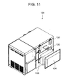
- the cascade heat exchanger 130 is provided with an externally opened storage recess portion 133 beforehand secured in the back surface of the insulating box body 132 constituting the main body of the refrigeration apparatus 135, and the heat exchanger is incorporated after foaming an insulating material of the insulating box body 132 (see Japanese Patent Application Laid-Open No. 2000-105047 ).
- the insulating material is positioned, and a flat-plate-like insulating material 134 is received in a space between the storage recess portion 133 and the cascade heat exchanger 130 so as to cover the whole opening.
- the cascade heat exchanger 130 has a low temperature of about -40°C, dew might be attached to the outer surface of the main body around the heat exchanger. Therefore, the corresponding part needs to be sufficiently insulated, and an insulating structure is constituted so that the thickness of the insulating material 134 is remarkably increased, and the material is covered with a cover part from the outside.
- an insulating structure is constituted so that the thickness of the insulating material 134 is remarkably increased, and the material is covered with a cover part from the outside.
- a protruding part corresponding to the thickness of the insulating material 134 is present in the back surface part of the main body, which causes a problem that the protruding part disturbs the installation of the refrigeration apparatus 135.
- a constitution is employed in which the insulating material covering the back surface of the cascade heat exchanger is covered with an inner cover, a second insulating material and an outer cover covering the material are provided outside the inner cover, and the outer cover is detachably attached to the inner cover with a plurality of small screws.
- the carrying operation of the refrigeration apparatus is performed in a state in which the outer cover is removed, which avoids a disadvantage that the protruding part is stuck in the carrying entrance as described above.
- the present invention has been developed to solve the conventional technical problem, and an object thereof is to provide a refrigeration apparatus including a cascade heat exchanger and capable of reducing the depth dimension of the apparatus itself without being influenced by the thickness dimension of an insulating material for covering the cascade heat exchanger, so that the apparatus can easily be carried indoors through a usual carrying entrance.
- a refrigeration apparatus of the present invention is characterized by comprising: a high-temperature-side refrigerant circuit and a low-temperature-side refrigerant circuit each constituting an independent refrigerant closed circuit in which a refrigerant discharged from a compressor is condensed and then evaporated to exert a cooling function, an evaporator of the high-temperature-side refrigerant circuit and a condenser of the low-temperature-side refrigerant circuit constituting a cascade heat exchanger, an evaporator of the low-temperature-side refrigerant circuit being configured to cool a storage chamber constituted in an insulating box body to an extremely low temperature, the refrigeration apparatus further comprising: a mechanical chamber which is constituted by the side of the insulating box body and in which the compressor and the like are installed; and an insulating structure in which the periphery of the cascade heat exchanger is surrounded with an insulating material and which is arranged in a side wall of the insulating box body on the
- a refrigeration apparatus of the invention of a second aspect is characterized by comprising: a compressor; a condenser; an evaporator; and a plurality of intermediate heat exchangers and a plurality of pressure reducing units connected in series so that a refrigerant fed back from the evaporator circulates, wherein a plurality of types of non-azeotropic mixed refrigerants are introduced, a condensed refrigerant in the refrigerants passed through the condenser is allowed to join the intermediate heat exchanger through the pressure reducing unit, a non-condensed refrigerant in the refrigerants is cooled by the intermediate heat exchanger to successively condense the refrigerant having a lower boiling point, and the refrigerant having the lowest boiling point is allowed to flow into the evaporator through the final stage of the pressure reducing unit, to cool a storage chamber constituted in the insulating box body to an extremely low temperature, the refrigeration apparatus further comprising: a mechanical chamber which is constituted by the side
- a refrigeration apparatus of the invention of a third aspect is characterized by comprising: a high-temperature-side refrigerant circuit and a low-temperature-side refrigerant circuit each constituting an independent refrigerant closed circuit in which a refrigerant discharged from a compressor is condensed and then evaporated to exert a cooling function, the low-temperature-side refrigerant circuit having the compressor, a condenser, an evaporator, and a plurality of intermediate heat exchangers and a plurality of pressure reducing units connected in series so that the refrigerant fed back from the evaporator circulates, wherein a plurality of types of non-azeotropic mixed refrigerants are introduced, a condensed refrigerant in the refrigerants passed through the condenser is allowed to join the intermediate heat exchanger through the pressure reducing unit, a non-condensed refrigerant in the refrigerants is cooled by the intermediate heat exchanger to successively condense the refrigerant
- a refrigeration apparatus of the invention of a fourth aspect is characterized in that in the above inventions, the insulating box body is formed of a composite constitution of vacuum insulating panels and a foam insulating material, and the vacuum insulating panels are arranged in front and rear walls of the insulating box body and a side wall of the insulating box body on a side opposite to the mechanical chamber.
- a refrigeration apparatus of the invention of a fifth aspect is characterized in that in the above inventions, the insulating structure is detachably inserted from the backside, the front side or the upside.
- a refrigeration apparatus of the invention of a sixth aspect is characterized in that in the above invention, a pipe from the insulating structure is opposed to the surface in a direction in which the insulating structure is inserted or removed.
- the refrigeration apparatus comprises the high-temperature-side refrigerant circuit and the low-temperature-side refrigerant circuit each constituting the independent refrigerant closed circuit in which the refrigerant discharged from the compressor is condensed and then evaporated to exert the cooling function.
- the evaporator of the high-temperature-side refrigerant circuit and the condenser of the low-temperature-side refrigerant circuit constitute the cascade heat exchanger, and the evaporator of the low-temperature-side refrigerant circuit is configured to cool the storage chamber constituted in the insulating box body to the extremely low temperature.
- the refrigeration apparatus further comprises the mechanical chamber which is constituted by the side of the insulating box body and in which the compressor and the like are installed, and the insulating structure in which the periphery of the cascade heat exchanger is surrounded with the insulating material and which is arranged in the side wall of the insulating box body on the side of the mechanical chamber. Therefore, as compared with a case where the cascade heat exchanger is installed on the back surface portion of the insulating box body, the depth dimension of the whole apparatus can be reduced.
- the apparatus is stuck in a usual carrying entrance. Therefore, the refrigeration apparatus can easily be carried inwards or outwards without especially reducing a storage volume. Moreover, even in an installation place, the insulating structure for surrounding the cascade heat exchanger does not protrude externally from the back surface of the apparatus, so that an area required for installation can be decreased.
- the refrigeration apparatus comprises the compressor, the condenser, the evaporator, and the plurality of intermediate heat exchangers and the plurality of pressure reducing units connected in series so that the refrigerant fed back from the evaporator circulates.
- the plurality of types of non-azeotropic mixed refrigerants are introduced, the condensed refrigerant in the refrigerants passed through the condenser is allowed to join the intermediate heat exchanger through the pressure reducing unit, the non-condensed refrigerant in the refrigerants is cooled by the intermediate heat exchanger to successively condense the refrigerant having the lower boiling point, and the refrigerant having the lowest boiling point is allowed to flow into the evaporator through the final stage of the pressure reducing unit, to cool the storage chamber constituted in the insulating box body to the extremely low temperature.
- the refrigeration apparatus further comprises the mechanical chamber which is constituted by the side of the insulating box body and in which the compressor and the like are installed, and the insulating structure in which the periphery of each intermediate heat exchanger is surrounded with the insulating material and which is arranged in the side wall of the insulating box body on the side of the mechanical chamber. Therefore, as compared with a case where the insulating structure in which the periphery of each intermediate heat exchanger is surrounded with the insulating material is installed on the back surface portion of the insulating box body as in the conventional example, the depth dimension of the whole apparatus can be reduced.
- the refrigeration apparatus comprises the high-temperature-side refrigerant circuit and the low-temperature-side refrigerant circuit each constituting the independent refrigerant closed circuit in which the refrigerant discharged from the compressor is condensed and then evaporated to exert the cooling function.
- the low-temperature-side refrigerant circuit has the compressor, the condenser, the evaporator, and the plurality of intermediate heat exchangers and the plurality of pressure reducing units connected in series so that the refrigerant fed back from the evaporator circulates.
- the plurality of types of non-azeotropic mixed refrigerants are introduced, the condensed refrigerant in the refrigerants passed through the condenser is allowed to join the intermediate heat exchanger through the pressure reducing unit, the non-condensed refrigerant in the refrigerants is cooled by the intermediate heat exchanger to successively condense the refrigerant having the lower boiling point, the refrigerant having the lowest boiling point is allowed to flow into the evaporator through the final stage of the pressure reducing unit, the evaporator of the high-temperature-side refrigerant circuit and the condenser of the low-temperature-side refrigerant circuit constitute the cascade heat exchanger, and the evaporator of the low-temperature-side refrigerant circuit is configured to cool the storage chamber constituted in the insulating box body to the extremely low temperature.
- the refrigeration apparatus further comprises the mechanical chamber which is constituted by the side of the insulating box body and in which the compressor and the like are installed, and the insulating structure in which the peripheries of the cascade heat exchanger and each intermediate heat exchanger are surrounded with the insulating material and which is arranged in the side wall of the insulating box body on the side of the mechanical chamber. Therefore, as compared with a case where the insulating structure in which the peripheries of the cascade heat exchanger and each intermediate heat exchanger are surrounded with the insulating material is installed on the back surface portion of the insulating box body as in the conventional example, the depth dimension of the whole apparatus can be reduced.
- the apparatus is stuck in the usual carrying entrance. Therefore, the refrigeration apparatus can easily be carried inwards or outwards without especially reducing the storage volume. Moreover, even in the installation place, the insulating structure for surrounding the peripheries of the cascade heat exchanger and each intermediate heat exchanger does not protrude externally from the back surface of the apparatus, so that the area required for installation can be decreased.
- the insulating box body is formed of the composite constitution of the vacuum insulating panels and the foam insulating material, and the vacuum insulating panels are arranged in the front and rear walls of the insulating box body and the side wall of the insulating box body on the side opposite to the mechanical chamber.
- the back surface of the insulating box body is not provided with the insulating structure for surrounding the peripheries of the cascade heat exchanger and each intermediate heat exchanger. Therefore, the vacuum insulating panels can be arranged in the front and rear walls of the insulating box body and the side wall of the insulating box body on the side opposite to the mechanical chamber without being influenced by the insulating structure. Consequently, the leakage of cold from the storage chamber can be decreased, and the wasting of useless cooling energy can be suppressed.
- the vacuum insulating panels are arranged in the front and rear walls of the insulating box body constituted so as to face the outside and the side wall of the insulating box body on the side opposite to the mechanical chamber. Therefore, even when the storage chamber is cooled to an extremely low temperature of, for example, -80°C or less, the insulating performance of the insulating box body itself can be improved, and dimensions can be reduced. Even when an outer dimension is similar to that of the conventional example, a storage volume in the storage chamber can be enlarged. Alternatively, even when the storage volume is similar to that of the conventional example, the outer dimension can be reduced. In consequence, an area required for installing the refrigeration apparatus can be decreased.
- the insulating structure is detachably inserted from the backside, the front side or the upside.
- the insulating structure in which the cascade heat exchanger and the intermediate heat exchangers are integrated with the insulating material is inserted from the backside, the front side or the upside, the cascade heat exchanger and the intermediate heat exchangers can easily be assembled in the main body, and assembling operability can be improved.
- the integrated insulating structure is extracted to the backside, the front side or the upside, the insulating structure can be removed from the main body, and a maintenance operation of the cascade heat exchanger and the intermediate heat exchangers can easily be performed.
- the pipe from the insulating structure is opposed to the surface in the direction in which the insulating structure is inserted or removed.
- the insulating structure is finally inserted.
- pipes from the mechanical chamber side or the insulating box body side can easily be connected, and piping operability and assembling operability can be improved.
- FIG. 1 is a perspective view of a refrigeration apparatus 1 to which the present invention is applied
- FIG. 2 is a front view of the refrigeration apparatus 1
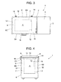
- FIG. 3 is a plan view of the refrigeration apparatus 1
- FIG. 4 is a side view in a state in which a storage chamber 4 is seen through the refrigeration apparatus 1
- FIG. 5 is a perspective view of the refrigeration apparatus 1 in a state in which a top panel 5 is opened.
- the refrigeration apparatus 1 of the present embodiment is suitable for storing, at an extremely low temperature, for example, a living tissue, a specimen or the like to be stored at a low temperature for a long time, and a main body of the apparatus is constituted of an insulating box body 2 which opens in an upper surface, and a mechanical chamber 3 which is positioned by the side of the insulating box body 2 and in which a compressor 10 and the like are installed.
- This insulating box body 2 is constituted of an outer box 6 made of a steel plate and an inner box 7 made of a satisfactorily thermally conductive metal such as aluminum, the boxes having opened upper surfaces.
- the insulating box body is also constituted of a breaker 8 connecting the upper ends of both the boxes 6, 7 to each other, and an insulating material 9 with which a space surrounded by the outer box 6, the inner box 7 and the breaker 8 is filled by an on-site foam system and which is made of a polyurethane resin.
- the inside of the inner box 7 is the storage chamber 4 having an open upper surface.
- a targeted temperature (hereinafter referred to as the in-chamber temperature) in the storage chamber 4 is set to, for example, -150°C or less. Therefore, the insulating box body 2 which separates the inside of the storage chamber 4 and outside air needs to have large insulating capability against a set low in-chamber temperature around 0°C. Therefore, to secure the insulating capability only by the insulating material 9 made of the polyurethane resin, the material has to be formed to be remarkably thick. There is also a problem that a sufficient storage amount in the storage chamber 4 cannot be secured with a limited main body dimension.
- vacuum insulating panels 12 made of glass wool are arranged in the inner wall surfaces of a front wall 6A of the outer box 6, a rear wall 6B and a side wall 6C positioned on a side opposite to a side provided with the mechanical chamber 3.
- the panels are tentatively fixed with an adhesive double coated tape, and then a space between both the boxes 6 and 7 is filled with the insulating material 9 by the on-site foam system.
- this vacuum insulating panel 12 glass wool having insulating properties is received in a container constituted of a multilayered film made of aluminum, a synthetic resin or the like which does not have any gas permeability. Afterward, air is discharged from the container by predetermined vacuum exhaust means, and an opening of the container is thermally sealed and joined. In consequence, since the vacuum insulating panel 12 has the insulating performance, the thickness dimension of the insulating material 9 is decreased as compared with a conventional example, but the same insulating effect can be obtained.
- an evaporator (an evaporation pipe) 62 constituting a refrigerant circuit of a cooling apparatus R described later in detail is attached to the peripheral surface of the inner box 7 on the insulating material 9 side in a heat exchange manner.
- the upper surface of the breaker 8 of the insulating box body 2 having the above constitution is formed in a staircase-like shape, and an insulating door 13 is provided on the surface via a packing (not shown) so that the insulating door is rotatable around one end, that is, the rear end of the door in the present embodiment by pivotable members 14, 14.
- the upper-surface opening of the storage chamber 4 is provided with an openable/closable inner lid 15 constituted of an insulating material.
- the lower surface of the insulating door 13 is provided with a pressing portion configured to protrude downwards.
- the pressing portion of the insulating door 13 presses the inner lid 15 to openably close the upper-surface opening of the storage chamber 4.
- the other end, that is, the front end of the insulating door 13 in the present embodiment is provided with a handle portion 16, and the handle portion 16 is operated to open or close the insulating door 13.
- a front panel 3A, a rear panel (not shown) and a side panel 3B constituting a side surface on a side opposite to a side provided with the insulating box body 2 form the mechanical chamber 3.
- the mechanical chamber 3 of the present embodiment is provided with a partition plate 17 which divides the inside of the chamber into upper and lower chambers.
- the compressor 10, a compressor 20 and the like constituting the cooling apparatus R as described above are received and installed under the partition plate 17, and the front panel 3A and the side panel 3B positioned under the partition plate 17 are provided with slits 3C for ventilation.
- An upper mechanical chamber 18 having an opened upper surface is constituted above the partition plate 17.
- the upper-surface opening of the upper mechanical chamber 18 is provided with the top panel 5 so that the panel is rotatable around one end, that is, the rear end of the panel in the present embodiment, whereby the upper mechanical chamber 18 is openably closed.
- a panel positioned on the front surface of the upper mechanical chamber 18 is an operation panel 21 for operating the refrigeration apparatus 1.
- a side surface constituting this upper mechanical chamber 18 on the insulating box body 2 side is provided with a measurement hole 19.
- This measurement hole 19 is extended through the outer box 6, the insulating material 9 and the inner box 7 constituting the insulating box body 2 so as to communicate with the storage chamber 4 formed in the insulating box body 2 provided adjacent to the measurement hole.
- a temperature sensor can be inserted into the storage chamber 4 from the outside, and a wiring line drawn from the temperature sensor is connected to an external recording apparatus main body through the measurement hole 19.
- a gap between this measurement hole 19 and the wiring line is closed by a plug 19A constituted of a sponge-like deformable special material having insulating properties. It is to be noted that the measurement hole 19 is closed by the plug 19A in an insulating manner in a state in which the temperature sensor is not attached to the hole.
- the top panel 5 provided in the mechanical chamber 3 is opened, and the measuring instrument can be inserted into the storage chamber 4 through the measurement hole 19 formed in the side surface of the insulating box body 2 positioned in the upper mechanical chamber 18. This can facilitate an operation of installing the measuring instrument in the storage chamber 4 cooled to a predetermined extremely low temperature.
- the measurement hole 19 of the present embodiment is formed in the side surface of the insulating box body 2 on the mechanical chamber 18 side. Therefore, even when the refrigeration apparatus 1 is installed adjacent to the wall of an installation environment such as the laboratory, or another device, a space necessary for using the measurement hole 19 does not especially have to be disposed. In consequence, an area required for installing the refrigeration apparatus 1 can be decreased, which is suitable for determining the layout of the laboratory or the like.
- the vacuum insulating panels 12 can be provided in the side surface other than the side surface adjacent to the mechanical chamber 3, that is, the front and rear walls and the side surface of the insulating box body 2 constituted so as to face the outside without influencing the forming position of the measurement hole 19.
- the wall surface of the insulating box body 2 provided with the measurement hole 19 is provided with an insulating structure 70 in which a cascade heat exchanger 43, an intermediate heat exchanger 48 and the like are integrally formed of the insulating material as described later in detail. Therefore, even when the vacuum insulating panel 12 is not provided, the inside of the storage chamber 4 can effectively be insulated by the insulating structure 70.
- the insulating performance of the insulating box body 2 itself can be improved, and the dimension of an insulating wall can be decreased.
- a storage volume in the storage chamber 4 can be increased.
- the outer dimension can be decreased. Even in this case, the area required for installing the refrigeration apparatus 1 can be decreased.
- the measurement hole 19 of the present embodiment can be covered with the top panel 5 which can openably close the upper-surface opening of the upper mechanical chamber 18, whereby the appearance of the apparatus has a constitution in which the measurement hole 19 is not exposed, and the appearance can be improved. Moreover, when the top panel 5 is opened, an operation can easily be performed with respect to the measurement hole 19, and operability can be improved. When the partition plate 17 is removed, another device constituting the cooling apparatus R installed under the partition plate 17 can easily be operated, and the efficiency of a maintenance operation can be improved.
- the mechanical chamber 18 is closed with the top panel 5 in a case other than the case where the operation is performed with respect to the measurement hole 19, so that the top panel 5 can be used as a side table for an operation, and the panel is convenient for an operation of storing articles such as samples in the storage chamber 4 or taking the articles from the chamber.
- the measurement hole 19 is covered with the top panel 5 which closes the upper-surface opening of the upper mechanical chamber 18, but this is not restrictive, and a lid member for covering the measurement hole 19 or the like may be provided in the vicinity of the measurement hole 19.
- the refrigerant circuit of the refrigeration apparatus 1 in the present embodiment is constituted of a two-dimensional two-stage refrigerant circuit, as a multi-dimensional multistage refrigerant circuit, including independent refrigerant circuits of a high-temperature-side refrigerant circuit 25 as a first refrigerant circuit and a low-temperature-side refrigerant circuit 38 as a second refrigerant circuit.
- the compressor 10 constituting the high-temperature-side refrigerant circuit 25 is an electromotive compressor using a one-phase or three-phase alternating-current power source, and a discharge side pipe 10D of the compressor 10 is connected to an auxiliary condenser 26.
- this auxiliary condenser 26 is connected to a refrigerant pipe 27 (hereinafter referred to as a frame pipe) arranged on the back side of this opening edge.
- this frame pipe 27 is connected to an oil cooler 29 of the compressor 10, and then connected to a condenser 28.
- the refrigerant pipe exiting from the condenser 28 is connected to an oil cooler 30 of the compressor 20 constituting the low-temperature-side refrigerant circuit 38, and is then connected to a condenser 31.
- the refrigerant pipe exiting from the condenser 31 is connected to an evaporator 34 as an evaporator portion constituting the evaporator successively via a drier 32 and a capillary tube 33 as a pressure reducing unit.
- An outlet side refrigerant pipe of the evaporator 34 is connected to an accumulator 35 as a refrigerant liquid reservoir, and the refrigerant pipe exiting from the accumulator 35 is connected to a suction side pipe 10S of the compressor 10.
- the auxiliary condenser 26 and the condensers 28 and 31 in the present embodiment are constituted as an integral condenser, and are cooled by a blower 36 for the condenser.
- the high-temperature-side refrigerant circuit 25 is filled with a refrigerant constituted of R407D and n-pentane as non-azeotropic refrigerants having different boiling points.
- R407D is constituted of R32 (difluoromethane: CH 2 F 2 ) , R125 (pentafluoroethane: CHF 2 CF 3 ), and R134a (1,1,1,2-tetrafluoroethane: CH 2 FCF 3 ), and a composition includes 15 wt% of R32, 15 wt% of R125 and 70 wt% of R134a.
- R32 has -51.8°C
- R125 has -48.57°C
- R134a has -26.16°C.
- the boiling point of n-pentane is +36.1°C.
- the high-temperature gas refrigerant discharged from the compressor 10 is condensed, releases heat and is liquefied by the auxiliary condenser 26, the frame pipe 27, the oil cooler 29, the condenser 28, the oil cooler 30 of the compressor 20 of the low-temperature-side refrigerant circuit 38 and the condenser 31. Afterward, a water content contained in the refrigerant is removed by the drier 32, and the pressure of the refrigerant is reduced by the capillary tube 33. The refrigerants successively flow into the evaporator 34 to evaporate the refrigerants R32, R125 and R134a. Then, vaporization heat is absorbed from a surrounding area to cool the evaporator 34, and the refrigerant returns to the compressor 10 through the accumulator 35 as the refrigerant liquid reservoir.
- the compressor 10 has a capability of, for example, 1.5 HP, and the final reaching temperature of the evaporator 34 which is being operated is in a range of -27°C to -35°C.
- the refrigerant does not evaporate in the evaporator 34 and still has a liquid state. Therefore, the refrigerant hardly contributes to cooling, but the refrigerant has a function of feeding the lubricant of the compressor 10 and a mixed water content which cannot completely be absorbed by the drier 32 back to the compressor 10 in a state in which the same is dissolved in the refrigerant.
- the refrigerant also has a function of lowering the temperature of the compressor 10 by the evaporation of the liquid refrigerant in the compressor 10.
- the compressor 20 of the low-temperature-side refrigerant circuit 38 is an electromotive compressor using a one-phase or three-phase alternating-current power source in the same manner as in the compressor 10, and a discharge side pipe 20D of the compressor 20 is connected to an oil separator 40 via a radiator 39 constituted of a wire condenser.
- This oil separator 40 is connected to an oil return tube 41 which returns to the compressor 20.
- a refrigerant pipe connected to the outlet side of the oil separator 40 is connected to a condensing pipe 42 as a high-pressure-side pipe inserted into the evaporator 34.
- This condensing pipe 42 constitutes a cascade heat exchanger 43 together with the evaporator 34.
- a discharge pipe connected to the outlet side of the condensing pipe 42 is connected to a first gas-liquid separator 46 via a drier 44.
- a gas-phase refrigerant separated by the gas-liquid separator 46 passes through the first intermediate heat exchanger 48 via a gas-phase pipe 47 to flow into a second gas-liquid separator 49.
- a liquid-phase refrigerant separated by the first gas-liquid separator 46 flows into the first intermediate heat exchanger 48 through a liquid-phase pipe 50, a drier 51 and a capillary tube 52 as a pressure reducing unit.
- the liquid-phase refrigerant separated by the second gas-liquid separator 49 flows into a second intermediate heat exchanger 56 through a liquid-phase pipe 53, a drier 54 and a capillary tube 55 as a pressure reducing unit.
- the gas-phase refrigerant separated by the second gas-liquid separator 54 is cooled and liquefied while passing through a gas-phase pipe 57, the second intermediate heat exchanger 56 and third and fourth intermediate heat exchangers 58, 59, and the refrigerant flows into a capillary tube 61 as a pressure reducing unit through a pipe 68 and a drier 60.
- the capillary tube 61 is connected to an evaporation pipe 62 as an evaporator, and the evaporation pipe 62 is connected to the fourth intermediate heat exchanger 59 via a return pipe 69.
- the fourth intermediate heat exchanger 59 is successively connected to the third, second and first intermediate heat exchangers 58, 56 and 48, and then connected to a suction side pipe 20S of the compressor 20.
- the suction side pipe 20S is further connected to expansion tanks 65 which store the refrigerant during the stop of the compressor 20 via a capillary tube 66 as a pressure reducing unit.
- the capillary tube 66 is connected in parallel with a check valve 67 in an expansion tank 65 direction as a forward direction.
- a non-azeotropic mixed refrigerant including R245fa, R600, R404A, R508, R14, R50 and R740 is introduced as a mixed refrigerant of seven types of refrigerants having different boiling points.
- R245fa is 1,1,1,-3,3-pentafluoropropane (CF 3 CH 2 CHF 2 ), and R600 is butane (CH 3 CH 2 CH 2 CH 3 ) .
- R245fa has a boiling point of +15.3°C
- R600 has a boiling point of -0.5°C. Therefore, when these refrigerants are mixed at a predetermined ratio, the mixed refrigerant can be used as a substitute for heretofore used R21 having a boiling point of +8.9°C.
- R600 is a combustible substance.
- the refrigerant is introduced as an incombustible refrigerant in the refrigerant circuit 38.
- R245fa is set to 70 wt% with respect to a total weight of R245fa and R600. Above this value, the refrigerant becomes incombustible. Therefore, the weight percentage may be set to this value or more.
- R404A is constituted of R125 (pentafluoroethane: CHF 2 CF 3 ), R143a (1,1,1-trifluoroethane: CH 3 CF 3 ) and R134a (1,1,1,2-tetrafluoroethane: CH 2 FCF 3 ), and a composition includes 44 wt% of R125, 52 wt% of R143a and 4 wt% of R134a.
- the mixed refrigerant has a boiling point of -46.48°C. Therefore, the refrigerant can be used as a substitute for heretofore used R22 having a boiling point of -40.8°C.
- R508 is constituted of R23 (trifluoromethane: CHF 3 ) and R116 (hexafluoroethane: CF 3 CF 3 ), and a composition includes 39 wt% of R23 and 61 wt% of R116.
- the mixed refrigerant has a boiling point of -88.64°C.
- R14 is tetrafluoromethane (carbon tetrafluoride: CF 4 ), R50 is methane (CH 4 ) and R740 is argon (Ar).
- R14 has a boiling point of -127.9°C
- R50 has -161.5°C
- R740 has -185.86°C. It is to be noted that R50 might cause explosion when coupled with oxygen, but when R50 is mixed with R14, the danger of the explosion is eliminated. Therefore, even if a mixed refrigerant leakage accident occurs, any explosion is not generated.
- R245fa and R600, and R14 and R50 are beforehand mixed once in an incombustible state.
- the mixed refrigerant of R245fa and R600, R404A, R5080A, the mixed refrigerant of R14 and R50, and R740 are beforehand mixed, and introduced into the refrigerant circuit.
- R245fa and R600, R404A, R508A, R14 and R50, and R740 are introduced in this order from the refrigerant having the highest boiling point.
- composition of the refrigerants includes, for example, 10.3 wt% of the mixed refrigerant of R245fa and R600, 28 wt% of R404A, 29.2 wt% of R508A, 26.4 wt% of the mixed refrigerant of R14 and R50 and 5.1 wt% of R740.
- n-pentane in a range of 0.5 to 2 wt% with respect to the total weight of the non-azeotropic refrigerants
- R404A 4 wt% of n-pentane (in a range of 0.5 to 2 wt% with respect to the total weight of the non-azeotropic refrigerants) may be added to R404A.
- the high-temperature high-pressure gas mixed refrigerant discharged from the compressor 20 flows into the radiator 39 via the discharge side pipe 20D, and radiates heat in the radiator. Then, a part of n-pentane or R600 as an oil carrier refrigerant having a high boiling point and a satisfactory oil solubility in the mixed refrigerant is condensed and liquefied.
- the mixed refrigerant discharged from the radiator 39 flows into the oil separator 40, and a large part of lubricating oil of the compressor 20 mixed with the refrigerant and a part (a part of n-pentane or R600) of the refrigerant condensed and liquefied in the radiator 39 are fed back to the compressor 20 via the oil return tube 41.
- the refrigerant having higher purity and lower boiling point flows into the refrigerant circuit 38 after the cascade heat exchanger 43, and the extremely low temperature can efficiently be obtained. Therefore, even the compressors 10 and 20 having the same capability can cool the inside of the storage chamber 4 as a cooling target having a larger volume to a predetermined extremely low temperature, and the storage capacity can be increased without enlarging the whole refrigeration apparatus 1.
- the refrigerant fed into the oil separator 40 is once cooled in the radiator 39, and hence the temperature of the refrigerant flowing into the cascade heat exchanger 43 can be lowered.
- the temperature of the refrigerant fed into the cascade heat exchanger 43 has heretofore been about +65°C, but the temperature can be lowered to about +45°C in the present embodiment.
- a load to be applied to the compressor of the high-temperature-side refrigerant circuit 25 for cooling the refrigerant in the low-temperature-side refrigerant circuit 35 can be decreased.
- the load to be applied to the compressor 20 constituting the low-temperature-side refrigerant circuit 35 can be decreased. In consequence, the operation efficiency of the whole refrigeration apparatus 1 can be improved.
- Another mixed refrigerant itself is cooled to about -40°C to -30°C by the evaporator 34 in the cascade heat exchanger 43 to condense and liquefy a part of the refrigerants (a part of R245fa, R600, R404A and R508) having the high boiling point in the mixed refrigerant. Then, the mixed refrigerant discharged from the condensing pipe 42 of the cascade heat exchanger 43 flows into the first gas-liquid separator 46 through the drier 44.
- R14, R50 and R740 in the mixed refrigerant have a remarkably low boiling point, the refrigerants are not condensed yet, and have a gas state, and an only part of R245fa, R600, R404A and R508 is condensed and liquefied. Therefore, R14, R50 and R740 are separated to the gas-phase pipe 47, and R245fa, R600, R404A and R508 are separated to the liquid-phase pipe 50.
- the refrigerant mixture which has flowed into the gas-phase pipe 47 performs heat exchange between the mixture and the first intermediate heat exchanger 48, is condensed, and then reaches the second gas-liquid separator 49.
- the low-temperature refrigerant returning from the evaporation pipe 62 flows into the first intermediate heat exchanger 48.
- the liquid refrigerant which has flowed into the liquid-phase pipe 50 flows through the drier 51 to reach the capillary tube 52 where the pressure of the refrigerant is reduced. Afterward, the refrigerant flows into the first intermediate heat exchanger 48 to evaporate in the exchanger, thereby contributing to the cooling.
- the first intermediate heat exchanger 48 has an intermediate temperature of about -60°C. Therefore, R508 in the mixed refrigerant which has passed through the gas-phase pipe 47 is completely condensed and liquefied, and branched to the second gas-liquid separator 49.
- R14, R50 and R740 have a lower boiling point, and hence still have a gas state.
- the drier 54 removes the water content from R508 branched by the second gas-liquid separator 49, and the pressure of the refrigerant is reduced by the capillary tube 55. Afterward, the refrigerant flows into the second intermediate heat exchanger 56, R14, R50 and R740 in the gas-phase pipe 57 are cooled together with the low-temperature refrigerant returning from the evaporation pipe 62, and R14 having the highest evaporation temperature among these refrigerants is condensed. In consequence, the second intermediate heat exchanger 56 has an intermediate temperature of about -90°C.
- the gas-phase pipe 57 passing through this second intermediate heat exchanger 56 subsequently passes through the third intermediate heat exchanger 58 and the fourth intermediate heat exchanger 59.
- the refrigerant immediately discharged from the evaporation pipe 62 is fed back to the fourth intermediate heat exchanger 59.
- the fourth intermediate heat exchanger 59 reaches a considerably low intermediate temperature of about -130°C.
- the refrigerants still having a gas phase state are successively condensed in the intermediate heat exchangers 48, 56, 58 and 59 by use of an evaporation temperature difference between the refrigerants in the low-temperature-side refrigerant circuit 38, and an extremely low temperature of -150°C or less can be achieved in the evaporation pipe 42 as a final stage. Therefore, the evaporation pipe 62 is wound along the insulating material 9 side of the inner box 6 in a heat exchange manner, so that an in-chamber temperature of -152°C or less can be realized in the storage chamber 4 of the refrigeration apparatus 1.
- the refrigerant discharged from the evaporation pipe 62 successively flows into the fourth intermediate heat exchanger 59, the third intermediate heat exchanger 58, the second intermediate heat exchanger 56 and the first intermediate heat exchanger 48, and the refrigerant joins the refrigerants evaporated in the respective heat exchangers, and returns the compressor 20 via the suction side pipe 20S.
- a large part of the oil mixed with the refrigerant and discharged from the compressor 20 is separated by the oil separator 40 and returned to the compressor 20.
- the mist-like oil discharged from the oil separator 40 together with the refrigerant is returned to the compressor 20 in a state in which the oil is dissolved in R600 having high oil solubility. In consequence, the lubricating defect of the compressor 20, or locking can be prevented.
- R600 returns the compressor 20 while maintaining the liquid state, and is evaporated in this compressor 20, so that the discharge temperature of the compressor 20 can be lowered.
- the compressor 20 constituting the low-temperature-side refrigerant circuit 38 having the above constitution is subjected to ON-OFF control by a controller (not shown) based on the in-chamber temperature of the storage chamber 4.
- a controller not shown
- the mixed refrigerant in the low-temperature-side refrigerant circuit 38 is collected in the expansion tank 65 via the check valve 67 having the expansion tank 65 direction as the forward direction.
- the refrigerant in the refrigerant circuit 38 can remarkably quickly be collected in the expansion tank 65 via the check valve 67.
- the rise of the pressure in the refrigerant circuit 38 can be prevented.
- the compressor 20 is started by the controller, the refrigerant is gradually returned from the expansion tank 65 to the refrigerant circuit 38 via the capillary tube 66, and the starting load of the compressor 20 can be decreased.
- the evaporation pipe 62 of the low-temperature-side refrigerant circuit 38 has an extremely low temperature in a range of -160.3°C to -157.3°C, and even the cascade heat exchanger 43 has a low temperature in a range of about -40°C to -30°C.
- the first intermediate heat exchanger 48 has an extremely low temperature of about -60°C
- the second intermediate heat exchanger 56 has about -90°C
- the third and fourth intermediate heat exchangers 58, 59 have about -130°C. Therefore, even the heat exchanger 43 and the like excluding the evaporation pipe 62 arranged in the insulating box body 2 need to be sufficiently insulated.
- FIG. 7 shows a perspective view of the insulating structure 70
- FIG. 8 shows a perspective view in a state in which an insulating material of the insulating structure 70 has been removed.
- the insulating structure 70 is, in addition to the above heat exchangers, the accumulator 35 and the capillary tube 33 constituting the high-temperature-side refrigerant circuit 25, and the drier 44, the gas-liquid separators 46, 49, the driers 51, 54 and the capillary tubes 52, 55 constituting the low-temperature-side refrigerant circuit 38 constitute the insulating structure 70.
- the cascade heat exchanger 43 is arranged on one end of the insulating structure 70, and the intermediate heat exchangers 48, 56, 58 and 59 are positioned by the side of this cascade heat exchanger 43 and arranged in layers.
- Each of the intermediate heat exchangers 48, 56, 58 and 59 has a spiral double pipe structure in which an outer pipe having a comparatively large diameter is spirally wound as much as a plurality of stages, the resultant flat pipes are superimposed on one another, and each of the gas-phase pipes 47, 57 passes as an inner pipe on the inner side from the outer pipe with a space being left between the pipes.
- the exchanges are arranged in order from the exchanger having the lowest temperature, that is, the fourth and third intermediate heat exchangers 58, 59 are arranged in the lowermost layer, the second intermediate heat exchanger 56 is arranged on the exchangers, and the first intermediate heat exchanger 48 is arranged in the uppermost layer.
- the gas-liquid separators 46, 49 (it is to be noted that the second gas-liquid separator 49 is not shown in FIG. 8 ), the driers 44, 51 and 54 (not shown in FIG. 8 ), the capillary tubes 33, 52 and 55 (not shown) and the accumulator 35 are arranged, a dead space is decreased, and dimensions are decreased.
- pipes connecting devices arranged in the insulating structure 70 to those arranged outside the insulating structure 70 are arranged so as to face a one-end side surface on a side opposite to a side provided with the cascade heat exchanger 34.
- the suction side pipes 10S, 20S and the discharge side pipe 20D through which the refrigerant having a comparatively high temperature circulates are bundled and externally arranged toward the mechanical chamber 3 in a state in which the insulating structure 70 is attached to the insulating box body 2 in the present embodiment.
- the pipe 68 and the return pipe 69 which are connected to the evaporation pipe 62 and through which the extremely low temperature refrigerant circulates are converged and externally arranged toward the insulating box body 2 on a side opposite to the suction side pipe 10S and the like in the state in which the insulating structure 70 is attached to the insulating box body 2 in the present embodiment.
- the drier 60 and the capillary tube 61 connected to the pipe 68 are arranged outside the insulating structure 70.
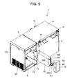
- FIG. 9 shows a back perspective view of the refrigeration apparatus 1.
- the side wall of the insulating box body 2 positioned on the mechanical chamber 3 side is provided with a rectangular opening 71 extending in a front-to-rear direction and opening rearwards, and the rear part of the side wall on the mechanical chamber 3 side is provided with a cutout 72 corresponding to the opening 71.
- the insulating structure 70 is inserted into this opening 71 from the backside of the insulating box body 2. At this time, the insulating structure 70 is inserted into the opening 71 from the side provided with the cascade heat exchanger 34.
- the pipes 10S, 20S, 20D, 68 and 69 arranged so as to extend on one side of the insulating structure 70, and the pipe 10D connected to the capillary tube 33 of the high-temperature-side refrigerant circuit 25 are opposed to the surface in a direction in which the insulating structure 70 is inserted or removed, that is, the back surface of the insulating box body 2 in the present embodiment.
- the insulating structure 70 is finally inserted into the opening 71.
- the pipes 68, 69 are connected to the evaporation pipe 62 provided on the insulating box body 2 side, and the pipes 10S, 10D, 20S and 20D are connected to the pipes of the devices on the mechanical chamber 3 side.
- the devices constituting the insulating structure 70 can easily be connected to the evaporation pipe 62 arranged in the insulating box body 2 and the pipes of devices such as the compressors 10, 20 arranged in the mechanical chamber 3 from the back surface of the insulating box body 2, and piping operation efficiency and assembling operation efficiency can be improved.
- the insulating structure 70 is drawn in a direction different from a direction in which the insulating box body 2 and the mechanical chamber 3 are constituted, and a maintenance operation can easily be performed.
- a part of the back surface from which the pipes of the insulating structure 70 extend and the side surface opposed to the mechanical chamber 3 side is closed by a cover member 73 bent so as to form a substantially L-shaped section.
- an insulating plate (not shown) filled with glass wool may be arranged in a gap formed between the insulating structure 70 and the side surface on the mechanical chamber 3 side.
- the cascade heat exchanger 43 and the intermediate heat exchangers 48, 56, 58 and 59 are arranged on the side wall of the insulating box body 2 on the mechanical chamber 3 side in a state in which the insulating structure 70 is integrally formed of the insulating material. Therefore, as compared with a case where the insulating structure 70 is installed in the back surface portion of the insulating box body 2 as in the conventional example, the depth dimension of the whole refrigeration apparatus 1 can be decreased.
- the depth dimension of the whole apparatus 1 increases owing to the presence of a protruding part constituted of the insulating structure 70 for surrounding the cascade heat exchanger 43 and the like.
- the whole depth dimension can be suppressed to about 765 mm.
- a disadvantage that the refrigeration apparatus is stuck in a usual carrying entrance in general, about 800 mm
- the insulating structure 70 can be carried inwards and outwards through the usual carrying entrance in a state in which the structure is attached to the apparatus 1. Therefore, in the installation place, the insulating structure 70 does not have to be disconnected from or connected to the main body, and a laborious operation can be avoided.
- the refrigeration apparatus 1 can easily be carried inwards or outwards.
- the insulating structure 70 for surrounding the cascade heat exchanger 43 and the like does not protrude externally from the back surface, and hence the area required for installation can be decreased.
- the back surface of the insulating box body 2 is not provided with the cascade heat exchanger or the insulating structure for surrounding the periphery of each intermediate heat exchanger. Therefore, as described above, the vacuum insulating panels 12 can be arranged in the front wall 6A and the rear wall 6B of the insulating box body 2 configured to face the outside and the side wall 6C opposite to the mechanical chamber side. Even at an extremely low temperature of, for example, -150°C or less in the storage chamber 4, the insulating performance of the insulating box body 2 itself can be improved. Therefore, even when the dimension can be decreased and the outer dimension is similar to that in the conventional example, the storage volume in the storage chamber 4 can be increased. Alternatively, even with the storage volume similar to that in the conventional example, the outer dimension can be decreased. Even in this case, the area required for installing the refrigeration apparatus 1 can be decreased.
- the insulating structure 70 can be inserted into or detached from the side wall of the insulating box body 2 from the backside, that is, the back surface of the refrigeration apparatus 1, but this is not restrictive, and the insulating structure may be inserted or detached from the front of the insulating box body 2 or the upside of the insulating box body.
- the cascade heat exchanger 43, the intermediate heat exchanger 48 and the like integrated as the insulating structure 70 can easily be incorporated in the apparatus 1 main body, and the assembling operation efficiency can be improved.
- the insulating structure 70 can be drawn to the front or the upside to remove the structure from the apparatus 1 main body, and the maintenance operation of the cascade heat exchanger 43, the intermediate heat exchanger 48 and the like constituting the insulating structure 70 can easily be performed.
- the cascade heat exchanger 43, the intermediate heat exchanger 48 and the like constituting the refrigeration apparatus 1 are integrally constituted.
- the only cascade heat exchanger 43, or the only intermediate heat exchanger 48 and the like may integrally be constituted as the insulating structure 70, and may detachably be arranged on the side wall of the insulating box body 2 as in the present embodiment.
- the refrigeration apparatus 1 of a two-dimensional multistage system has been described.
- the refrigerant circuit constituting the refrigeration apparatus 1 is constituted of the high-temperature-side refrigerant circuit 25 and the low-temperature-side refrigerant circuit 38 constituting independent refrigerant closed circuits so that the refrigerant discharged from the compressor 10 or 20 is condensed and then evaporated to exert a cooling function.
- the low-temperature-side refrigerant circuit 38 has the compressor 20, the condensing pipe 42, the evaporation pipe 62, a plurality of, specifically four intermediate heat exchangers 48, 56, 58 and 59 connected in series so that the refrigerant fed back from the evaporation pipe 62 circulates, and a plurality of, specifically three capillary tubes 42, 55 and 61.
- a plurality of types of non-azeotropic mixed refrigerants are introduced, and the condensed refrigerant in the refrigerants fed through the condensing pipe 42 joins each intermediate heat exchanger via each capillary tube.
- the non-condensed refrigerant in the refrigerants is cooled by the intermediate heat exchanger to successively condense the refrigerant having a lower boiling point.
- the refrigerant having the lowest boiling point is allowed to flow into the evaporation pipe 62 through the final-stage capillary tube 61.
- the evaporator 34 of the high-temperature-side refrigerant circuit 25 and the condensing pipe 42 of the low-temperature-side refrigerant circuit 38 constitute the cascade heat exchanger 43, and the extremely low temperature is obtained in the evaporation pipe 42 of the low-temperature-side refrigerant circuit 38.
- the present invention is not limited to this apparatus.
- the cascade heat exchanger 43 may be constituted in the insulating structure 70 as in the present embodiment, and the insulating structure 70 may detachably be inserted into the side surface of the insulating box body 2 on the mechanical chamber 3 side, so that a similar effect can be obtained.
- the respective intermediate heat exchangers may be constituted in the insulating structure 70 as in the present embodiment, and the insulating
Landscapes
- Engineering & Computer Science (AREA)
- Physics & Mathematics (AREA)
- Mechanical Engineering (AREA)
- Thermal Sciences (AREA)
- General Engineering & Computer Science (AREA)
- Chemical & Material Sciences (AREA)
- Combustion & Propulsion (AREA)
- Devices That Are Associated With Refrigeration Equipment (AREA)
Abstract
Description
- The present invention relates to a refrigeration apparatus including a high-temperature-side refrigerant circuit and a low-temperature-side refrigerant circuit each constituting an independent refrigerant closed circuit in which a refrigerant discharged from a compressor is condensed and then evaporated to exert a cooling function, an evaporator of the high-temperature-side refrigerant circuit and a condenser of the low-temperature-side refrigerant circuit constituting a cascade heat exchanger, an evaporator of the low-temperature-side refrigerant circuit being configured to cool a storage chamber constituted in an insulating box body to an extremely low temperature.
- Heretofore, a two-dimensional refrigeration apparatus has been used as a refrigeration apparatus having an extremely low temperature for use in storing, for example, cells, microorganisms and the like in a biological field.
FIG. 10 shows a refrigerant circuit diagram of arefrigeration apparatus 135 using the two-dimensional refrigeration apparatus. Arefrigerant circuit 100 is constituted of a high-temperature-side refrigerant cycle 101 and a low-temperature-side refrigerant cycle 102. A discharge-side pipe 103D of acompressor 103 constituting the high-temperature-side refrigerant cycle 101 is connected to anauxiliary condenser 105, and theauxiliary condenser 105 is connected to a frame pipe 104 (for the frame pipe, refer to aframe pipe 27 of the present application), and then connected to acondenser 107 via anoil cooler 106 of thecompressor 103. Thecondenser 107 is cooled by ablower 116 for the condenser. Moreover, an outlet-side refrigerant pipe of thecondenser 107 is connected to anevaporator 110 as an evaporator portion constituting the evaporator successively through adrier 108 and apressure reducing unit 109. An outlet-side refrigerant pipe of theevaporator 110 is connected to anaccumulator 111, and a refrigerant pipe exiting from theaccumulator 111 is connected to a suction-side pipe 103S of thecompressor 103. - On the other hand, a discharge-
side pipe 113D of acompressor 113 constituting the low-temperature-side refrigerant cycle 102 is connected to anoil separator 114, and a refrigerant pipe connected to the outlet side of thisoil separator 114 is connected to acondensing pipe 115 as a high-temperature-side pipe inserted into theevaporator 110. Thiscondensing pipe 115 constitutes acascade heat exchanger 130 together with theevaporator 110. - Moreover, a discharge pipe connected to the outlet side of the
condensing pipe 115 is connected to a first gas-liquid separator 116 through adrier 131, and the gas-phase refrigerant separated by the gas-liquid separator 116 passes through a firstintermediate heat exchanger 117 via a gas-phase pipe to flow into a second gas-liquid separator 118. A liquid-phase refrigerant separated by the gas-liquid separator 116 passes through adrier 119 and apressure reducing unit 120 via a liquid-phase pipe, flows into the firstintermediate heat exchanger 117, and evaporates the gas-phase refrigerant to cool. - The liquid-phase refrigerant separated by the second gas-
liquid separator 118 passes through adrier 121 and apressure reducing unit 122 via the liquid-phase pipe to flow into a secondintermediate heat exchanger 123. The gas-phase refrigerant separated by the second gas-liquid separator 118 passes through the secondintermediate heat exchanger 123 via the liquid-phase pipe, and passes through a thirdintermediate heat exchanger 124 and adrier 125 to flow into apressure reducing unit 126. Thepressure reducing unit 126 is connected to anevaporation pipe 127 as an evaporator arranged in a heat exchanging manner in an inner wall of aninsulating box body 132 of the refrigeration apparatus on a storage chamber side, and theevaporation pipe 127 is further connected to the thirdintermediate heat exchanger 124. - The third
intermediate heat exchanger 124 is successively connected to the second and first intermediate heat exchangers, and then connected to a suction-side pipe 113S of thecompressor 113. This suction-side pipe 113S is connected to anexpansion tank 128 for receiving the refrigerant during the stop of thecompressor 113 through apressure reducing unit 129. - In this
refrigeration apparatus 135, theevaporation pipe 127 of the low-temperature-side refrigerant cycle 102 reaches an extremely low temperature of -150°C or less, and even thecascade heat exchanger 130 reaches a low temperature of about -40°C. Therefore, acascade heat exchanger 130 part needs to be sufficiently insulated. In a conventional constitution, as shown inFIG. 11 , thecascade heat exchanger 130 is provided with an externally openedstorage recess portion 133 beforehand secured in the back surface of theinsulating box body 132 constituting the main body of therefrigeration apparatus 135, and the heat exchanger is incorporated after foaming an insulating material of the insulating box body 132 (see Japanese Patent Application Laid-Open No.2000-105047 - Moreover, in the peripheral surface of this
cascade heat exchanger 130, the insulating material is positioned, and a flat-plate-likeinsulating material 134 is received in a space between thestorage recess portion 133 and thecascade heat exchanger 130 so as to cover the whole opening. - However, since the
cascade heat exchanger 130 has a low temperature of about -40°C, dew might be attached to the outer surface of the main body around the heat exchanger. Therefore, the corresponding part needs to be sufficiently insulated, and an insulating structure is constituted so that the thickness of theinsulating material 134 is remarkably increased, and the material is covered with a cover part from the outside. However, when the thickness of theinsulating material 134 is increased, a protruding part corresponding to the thickness of theinsulating material 134 is present in the back surface part of the main body, which causes a problem that the protruding part disturbs the installation of therefrigeration apparatus 135. - In particular, in a case where the
refrigeration apparatus 135 is carried indoors, there sometimes occurs a disadvantage that the apparatus is stuck in the carrying entrance of an installation place and that it becomes difficult to carry the apparatus indoors. Therefore, to smoothly perform a carrying operation, in a case where a product is designed so that the thickness of the insulating material of this protruding part is secured over the whole main body, there is a problem that when an outer dimension is not increased, a volume in the storage chamber decreases. - To solve the problem, in a refrigerator disclosed in Japanese Patent Application Laid-Open No.
2000-105047 - However, according to such a constitution, even in the installation place, the protruding part is still present in the back surface part of the main body. Even in such a case, owing to the product design in which the thickness of the protruding part is secured over the whole main body, there has been a problem that the storage volume decreases with respect to a depth as the outer dimension. Moreover, there has been a problem that an operation of attaching the outer cover needs to be performed after the installation, thereby resulting in a laborious carrying operation.
- The present invention has been developed to solve the conventional technical problem, and an object thereof is to provide a refrigeration apparatus including a cascade heat exchanger and capable of reducing the depth dimension of the apparatus itself without being influenced by the thickness dimension of an insulating material for covering the cascade heat exchanger, so that the apparatus can easily be carried indoors through a usual carrying entrance.
- A refrigeration apparatus of the present invention is characterized by comprising: a high-temperature-side refrigerant circuit and a low-temperature-side refrigerant circuit each constituting an independent refrigerant closed circuit in which a refrigerant discharged from a compressor is condensed and then evaporated to exert a cooling function, an evaporator of the high-temperature-side refrigerant circuit and a condenser of the low-temperature-side refrigerant circuit constituting a cascade heat exchanger, an evaporator of the low-temperature-side refrigerant circuit being configured to cool a storage chamber constituted in an insulating box body to an extremely low temperature, the refrigeration apparatus further comprising: a mechanical chamber which is constituted by the side of the insulating box body and in which the compressor and the like are installed; and an insulating structure in which the periphery of the cascade heat exchanger is surrounded with an insulating material and which is arranged in a side wall of the insulating box body on the side of the mechanical chamber.
- A refrigeration apparatus of the invention of a second aspect is characterized by comprising: a compressor; a condenser; an evaporator; and a plurality of intermediate heat exchangers and a plurality of pressure reducing units connected in series so that a refrigerant fed back from the evaporator circulates, wherein a plurality of types of non-azeotropic mixed refrigerants are introduced, a condensed refrigerant in the refrigerants passed through the condenser is allowed to join the intermediate heat exchanger through the pressure reducing unit, a non-condensed refrigerant in the refrigerants is cooled by the intermediate heat exchanger to successively condense the refrigerant having a lower boiling point, and the refrigerant having the lowest boiling point is allowed to flow into the evaporator through the final stage of the pressure reducing unit, to cool a storage chamber constituted in the insulating box body to an extremely low temperature, the refrigeration apparatus further comprising: a mechanical chamber which is constituted by the side of the insulating box body and in which the compressor and the like are installed; and an insulating structure in which the periphery of each intermediate heat exchanger is surrounded with an insulating material and which is arranged in a side wall of the insulating box body on the side of the mechanical chamber.
- A refrigeration apparatus of the invention of a third aspect is characterized by comprising: a high-temperature-side refrigerant circuit and a low-temperature-side refrigerant circuit each constituting an independent refrigerant closed circuit in which a refrigerant discharged from a compressor is condensed and then evaporated to exert a cooling function, the low-temperature-side refrigerant circuit having the compressor, a condenser, an evaporator, and a plurality of intermediate heat exchangers and a plurality of pressure reducing units connected in series so that the refrigerant fed back from the evaporator circulates, wherein a plurality of types of non-azeotropic mixed refrigerants are introduced, a condensed refrigerant in the refrigerants passed through the condenser is allowed to join the intermediate heat exchanger through the pressure reducing unit, a non-condensed refrigerant in the refrigerants is cooled by the intermediate heat exchanger to successively condense the refrigerant having a lower boiling point, the refrigerant having the lowest boiling point is allowed to flow into the evaporator through the final stage of the pressure reducing unit, an evaporator of the high-temperature-side refrigerant circuit and the condenser of the low-temperature-side refrigerant circuit constitute a cascade heat exchanger, and the evaporator of the low-temperature-side refrigerant circuit is configured to cool a storage chamber constituted in the insulating box body to an extremely low temperature, the refrigeration apparatus further comprising: a mechanical chamber which is constituted by the side of the insulating box body and in which the compressor and the like are installed; and an insulating structure in which the peripheries of the cascade heat exchanger and each intermediate heat exchanger are surrounded with an insulating material and which is arranged in a side wall of the insulating box body on the side of the mechanical chamber.
- A refrigeration apparatus of the invention of a fourth aspect is characterized in that in the above inventions, the insulating box body is formed of a composite constitution of vacuum insulating panels and a foam insulating material, and the vacuum insulating panels are arranged in front and rear walls of the insulating box body and a side wall of the insulating box body on a side opposite to the mechanical chamber.
- A refrigeration apparatus of the invention of a fifth aspect is characterized in that in the above inventions, the insulating structure is detachably inserted from the backside, the front side or the upside.
- A refrigeration apparatus of the invention of a sixth aspect is characterized in that in the above invention, a pipe from the insulating structure is opposed to the surface in a direction in which the insulating structure is inserted or removed.
- According to the present invention, the refrigeration apparatus comprises the high-temperature-side refrigerant circuit and the low-temperature-side refrigerant circuit each constituting the independent refrigerant closed circuit in which the refrigerant discharged from the compressor is condensed and then evaporated to exert the cooling function. The evaporator of the high-temperature-side refrigerant circuit and the condenser of the low-temperature-side refrigerant circuit constitute the cascade heat exchanger, and the evaporator of the low-temperature-side refrigerant circuit is configured to cool the storage chamber constituted in the insulating box body to the extremely low temperature. The refrigeration apparatus further comprises the mechanical chamber which is constituted by the side of the insulating box body and in which the compressor and the like are installed, and the insulating structure in which the periphery of the cascade heat exchanger is surrounded with the insulating material and which is arranged in the side wall of the insulating box body on the side of the mechanical chamber. Therefore, as compared with a case where the cascade heat exchanger is installed on the back surface portion of the insulating box body, the depth dimension of the whole apparatus can be reduced.
- In consequence, it is possible to avoid a disadvantage that owing to the presence of a protruding part of the insulating structure for surrounding the cascade heat exchanger, the apparatus is stuck in a usual carrying entrance. Therefore, the refrigeration apparatus can easily be carried inwards or outwards without especially reducing a storage volume. Moreover, even in an installation place, the insulating structure for surrounding the cascade heat exchanger does not protrude externally from the back surface of the apparatus, so that an area required for installation can be decreased.
- According to the invention of the second aspect, the refrigeration apparatus comprises the compressor, the condenser, the evaporator, and the plurality of intermediate heat exchangers and the plurality of pressure reducing units connected in series so that the refrigerant fed back from the evaporator circulates. The plurality of types of non-azeotropic mixed refrigerants are introduced, the condensed refrigerant in the refrigerants passed through the condenser is allowed to join the intermediate heat exchanger through the pressure reducing unit, the non-condensed refrigerant in the refrigerants is cooled by the intermediate heat exchanger to successively condense the refrigerant having the lower boiling point, and the refrigerant having the lowest boiling point is allowed to flow into the evaporator through the final stage of the pressure reducing unit, to cool the storage chamber constituted in the insulating box body to the extremely low temperature. The refrigeration apparatus further comprises the mechanical chamber which is constituted by the side of the insulating box body and in which the compressor and the like are installed, and the insulating structure in which the periphery of each intermediate heat exchanger is surrounded with the insulating material and which is arranged in the side wall of the insulating box body on the side of the mechanical chamber. Therefore, as compared with a case where the insulating structure in which the periphery of each intermediate heat exchanger is surrounded with the insulating material is installed on the back surface portion of the insulating box body as in the conventional example, the depth dimension of the whole apparatus can be reduced.
- In consequence, it is possible to avoid the disadvantage that owing to the presence of the protruding part of the insulating structure for surrounding the periphery of each intermediate heat exchanger, the apparatus is stuck in the usual carrying entrance. Therefore, the refrigeration apparatus can easily be carried inwards or outwards without especially reducing the storage volume. Moreover, even in the installation place, the insulating structure for surrounding the periphery of each intermediate heat exchanger does not protrude externally from the back surface of the apparatus, so that the area required for installation can be decreased.
- According to the invention of the third aspect, the refrigeration apparatus comprises the high-temperature-side refrigerant circuit and the low-temperature-side refrigerant circuit each constituting the independent refrigerant closed circuit in which the refrigerant discharged from the compressor is condensed and then evaporated to exert the cooling function. The low-temperature-side refrigerant circuit has the compressor, the condenser, the evaporator, and the plurality of intermediate heat exchangers and the plurality of pressure reducing units connected in series so that the refrigerant fed back from the evaporator circulates. The plurality of types of non-azeotropic mixed refrigerants are introduced, the condensed refrigerant in the refrigerants passed through the condenser is allowed to join the intermediate heat exchanger through the pressure reducing unit, the non-condensed refrigerant in the refrigerants is cooled by the intermediate heat exchanger to successively condense the refrigerant having the lower boiling point, the refrigerant having the lowest boiling point is allowed to flow into the evaporator through the final stage of the pressure reducing unit, the evaporator of the high-temperature-side refrigerant circuit and the condenser of the low-temperature-side refrigerant circuit constitute the cascade heat exchanger, and the evaporator of the low-temperature-side refrigerant circuit is configured to cool the storage chamber constituted in the insulating box body to the extremely low temperature. The refrigeration apparatus further comprises the mechanical chamber which is constituted by the side of the insulating box body and in which the compressor and the like are installed, and the insulating structure in which the peripheries of the cascade heat exchanger and each intermediate heat exchanger are surrounded with the insulating material and which is arranged in the side wall of the insulating box body on the side of the mechanical chamber. Therefore, as compared with a case where the insulating structure in which the peripheries of the cascade heat exchanger and each intermediate heat exchanger are surrounded with the insulating material is installed on the back surface portion of the insulating box body as in the conventional example, the depth dimension of the whole apparatus can be reduced.
- In consequence, it is possible to avoid the disadvantage that owing to the presence of the protruding part of the insulating structure for surrounding the peripheries of the cascade heat exchanger and each intermediate heat exchanger, the apparatus is stuck in the usual carrying entrance. Therefore, the refrigeration apparatus can easily be carried inwards or outwards without especially reducing the storage volume. Moreover, even in the installation place, the insulating structure for surrounding the peripheries of the cascade heat exchanger and each intermediate heat exchanger does not protrude externally from the back surface of the apparatus, so that the area required for installation can be decreased.
- According to the invention of the fourth aspect, in the above inventions, the insulating box body is formed of the composite constitution of the vacuum insulating panels and the foam insulating material, and the vacuum insulating panels are arranged in the front and rear walls of the insulating box body and the side wall of the insulating box body on the side opposite to the mechanical chamber. In consequence, unlike the conventional example, the back surface of the insulating box body is not provided with the insulating structure for surrounding the peripheries of the cascade heat exchanger and each intermediate heat exchanger. Therefore, the vacuum insulating panels can be arranged in the front and rear walls of the insulating box body and the side wall of the insulating box body on the side opposite to the mechanical chamber without being influenced by the insulating structure. Consequently, the leakage of cold from the storage chamber can be decreased, and the wasting of useless cooling energy can be suppressed.
- In particular, the vacuum insulating panels are arranged in the front and rear walls of the insulating box body constituted so as to face the outside and the side wall of the insulating box body on the side opposite to the mechanical chamber. Therefore, even when the storage chamber is cooled to an extremely low temperature of, for example, -80°C or less, the insulating performance of the insulating box body itself can be improved, and dimensions can be reduced. Even when an outer dimension is similar to that of the conventional example, a storage volume in the storage chamber can be enlarged. Alternatively, even when the storage volume is similar to that of the conventional example, the outer dimension can be reduced. In consequence, an area required for installing the refrigeration apparatus can be decreased.
- According to the invention of the fifth aspect, in the above inventions, the insulating structure is detachably inserted from the backside, the front side or the upside. In consequence, the insulating structure in which the cascade heat exchanger and the intermediate heat exchangers are integrated with the insulating material is inserted from the backside, the front side or the upside, the cascade heat exchanger and the intermediate heat exchangers can easily be assembled in the main body, and assembling operability can be improved. Moreover, when the integrated insulating structure is extracted to the backside, the front side or the upside, the insulating structure can be removed from the main body, and a maintenance operation of the cascade heat exchanger and the intermediate heat exchangers can easily be performed.
- Moreover, according to the invention of the sixth aspect, in the above invention, the pipe from the insulating structure is opposed to the surface in the direction in which the insulating structure is inserted or removed. In consequence, after installing the compressor and the like in the mechanical chamber, the insulating structure is finally inserted. In this state, pipes from the mechanical chamber side or the insulating box body side can easily be connected, and piping operability and assembling operability can be improved.
-
-
FIG. 1 is a perspective view of a refrigeration apparatus to which the present invention is applied; -
FIG. 2 is a front view of the refrigeration apparatus ofFIG. 1 ; -
FIG. 3 is a plan view of the refrigeration apparatus ofFIG. 1 ; -
FIG. 4 is a side view in a state in which a storage chamber is seen through the refrigeration apparatus ofFIG. 1 ; -
FIG. 5 is a perspective view of the refrigeration apparatus in a state in which a top panel is opened; -
FIG. 6 is a refrigerant circuit diagram of the refrigeration apparatus ofFIG. 1 ; -
FIG. 7 is a perspective view of an insulating structure; -
FIG. 8 is a perspective view in a state in which an insulating material of the insulating structure has been removed; -
FIG. 9 is a rear perspective view of the refrigeration apparatus showing a state in which the insulating structure is attached; -
FIG. 10 is a refrigerant circuit diagram of a conventional refrigeration apparatus; and -
FIG. 11 is a rear perspective view of the conventional refrigeration apparatus. - An embodiment of the present invention will hereinafter be described with reference to the drawings.
FIG. 1 is a perspective view of arefrigeration apparatus 1 to which the present invention is applied,FIG. 2 is a front view of therefrigeration apparatus 1,FIG. 3 is a plan view of therefrigeration apparatus 1,FIG. 4 is a side view in a state in which astorage chamber 4 is seen through therefrigeration apparatus 1, andFIG. 5 is a perspective view of therefrigeration apparatus 1 in a state in which atop panel 5 is opened. Therefrigeration apparatus 1 of the present embodiment is suitable for storing, at an extremely low temperature, for example, a living tissue, a specimen or the like to be stored at a low temperature for a long time, and a main body of the apparatus is constituted of an insulatingbox body 2 which opens in an upper surface, and amechanical chamber 3 which is positioned by the side of the insulatingbox body 2 and in which acompressor 10 and the like are installed. - This insulating
box body 2 is constituted of anouter box 6 made of a steel plate and aninner box 7 made of a satisfactorily thermally conductive metal such as aluminum, the boxes having opened upper surfaces. The insulating box body is also constituted of abreaker 8 connecting the upper ends of both theboxes material 9 with which a space surrounded by theouter box 6, theinner box 7 and thebreaker 8 is filled by an on-site foam system and which is made of a polyurethane resin. The inside of theinner box 7 is thestorage chamber 4 having an open upper surface. - In the present embodiment, a targeted temperature (hereinafter referred to as the in-chamber temperature) in the
storage chamber 4 is set to, for example, -150°C or less. Therefore, the insulatingbox body 2 which separates the inside of thestorage chamber 4 and outside air needs to have large insulating capability against a set low in-chamber temperature around 0°C. Therefore, to secure the insulating capability only by the insulatingmaterial 9 made of the polyurethane resin, the material has to be formed to be remarkably thick. There is also a problem that a sufficient storage amount in thestorage chamber 4 cannot be secured with a limited main body dimension. - To solve the problem, in the insulating
box body 2 of the present embodiment,vacuum insulating panels 12 made of glass wool are arranged in the inner wall surfaces of afront wall 6A of theouter box 6, arear wall 6B and aside wall 6C positioned on a side opposite to a side provided with themechanical chamber 3. The panels are tentatively fixed with an adhesive double coated tape, and then a space between both theboxes material 9 by the on-site foam system. - To constitute this
vacuum insulating panel 12, glass wool having insulating properties is received in a container constituted of a multilayered film made of aluminum, a synthetic resin or the like which does not have any gas permeability. Afterward, air is discharged from the container by predetermined vacuum exhaust means, and an opening of the container is thermally sealed and joined.
In consequence, since thevacuum insulating panel 12 has the insulating performance, the thickness dimension of the insulatingmaterial 9 is decreased as compared with a conventional example, but the same insulating effect can be obtained. - On the other hand, an evaporator (an evaporation pipe) 62 constituting a refrigerant circuit of a cooling apparatus R described later in detail is attached to the peripheral surface of the
inner box 7 on the insulatingmaterial 9 side in a heat exchange manner. - Moreover, as shown in
FIGS. 2 and4 , the upper surface of thebreaker 8 of the insulatingbox body 2 having the above constitution is formed in a staircase-like shape, and an insulatingdoor 13 is provided on the surface via a packing (not shown) so that the insulating door is rotatable around one end, that is, the rear end of the door in the present embodiment bypivotable members storage chamber 4 is provided with an openable/closableinner lid 15 constituted of an insulating material. Moreover, the lower surface of the insulatingdoor 13 is provided with a pressing portion configured to protrude downwards. In consequence, the pressing portion of the insulatingdoor 13 presses theinner lid 15 to openably close the upper-surface opening of thestorage chamber 4. Moreover, the other end, that is, the front end of the insulatingdoor 13 in the present embodiment is provided with ahandle portion 16, and thehandle portion 16 is operated to open or close the insulatingdoor 13. - On the other hand, by the side of the insulating
box body 2, afront panel 3A, a rear panel (not shown) and aside panel 3B constituting a side surface on a side opposite to a side provided with the insulatingbox body 2 form themechanical chamber 3. Themechanical chamber 3 of the present embodiment is provided with apartition plate 17 which divides the inside of the chamber into upper and lower chambers. Thecompressor 10, acompressor 20 and the like constituting the cooling apparatus R as described above are received and installed under thepartition plate 17, and thefront panel 3A and theside panel 3B positioned under thepartition plate 17 are provided withslits 3C for ventilation. - An upper
mechanical chamber 18 having an opened upper surface is constituted above thepartition plate 17. The upper-surface opening of the uppermechanical chamber 18 is provided with thetop panel 5 so that the panel is rotatable around one end, that is, the rear end of the panel in the present embodiment, whereby the uppermechanical chamber 18 is openably closed. It is to be noted that a panel positioned on the front surface of the uppermechanical chamber 18 is anoperation panel 21 for operating therefrigeration apparatus 1. - A side surface constituting this upper
mechanical chamber 18 on the insulatingbox body 2 side is provided with ameasurement hole 19. Thismeasurement hole 19 is extended through theouter box 6, the insulatingmaterial 9 and theinner box 7 constituting the insulatingbox body 2 so as to communicate with thestorage chamber 4 formed in the insulatingbox body 2 provided adjacent to the measurement hole. Through themeasurement hole 19, a temperature sensor can be inserted into thestorage chamber 4 from the outside, and a wiring line drawn from the temperature sensor is connected to an external recording apparatus main body through themeasurement hole 19. Moreover, a gap between thismeasurement hole 19 and the wiring line is closed by aplug 19A constituted of a sponge-like deformable special material having insulating properties. It is to be noted that themeasurement hole 19 is closed by theplug 19A in an insulating manner in a state in which the temperature sensor is not attached to the hole. - In consequence, when an instrument for measuring or recording the temperature in the
storage chamber 4 is used, thetop panel 5 provided in themechanical chamber 3 is opened, and the measuring instrument can be inserted into thestorage chamber 4 through themeasurement hole 19 formed in the side surface of the insulatingbox body 2 positioned in the uppermechanical chamber 18. This can facilitate an operation of installing the measuring instrument in thestorage chamber 4 cooled to a predetermined extremely low temperature. - In particular, unlike a measurement hole provided in a conventional refrigeration apparatus, the
measurement hole 19 of the present embodiment is formed in the side surface of the insulatingbox body 2 on themechanical chamber 18 side. Therefore, even when therefrigeration apparatus 1 is installed adjacent to the wall of an installation environment such as the laboratory, or another device, a space necessary for using themeasurement hole 19 does not especially have to be disposed. In consequence, an area required for installing therefrigeration apparatus 1 can be decreased, which is suitable for determining the layout of the laboratory or the like. - Moreover, since the
measurement hole 19 is formed in the wall surface of the insulatingbox body 2 on a side adjacent to themechanical chamber 3, thevacuum insulating panels 12 can be provided in the side surface other than the side surface adjacent to themechanical chamber 3, that is, the front and rear walls and the side surface of the insulatingbox body 2 constituted so as to face the outside without influencing the forming position of themeasurement hole 19. - Furthermore, the wall surface of the insulating
box body 2 provided with themeasurement hole 19 is provided with an insulatingstructure 70 in which acascade heat exchanger 43, anintermediate heat exchanger 48 and the like are integrally formed of the insulating material as described later in detail. Therefore, even when thevacuum insulating panel 12 is not provided, the inside of thestorage chamber 4 can effectively be insulated by the insulatingstructure 70. - In consequence, the leakage of cold from the
storage chamber 4 can be decreased, and the wasting of useless cooling energy can be suppressed. - Therefore, even when the inside of the
storage chamber 4 has an extremely low temperature of, for example, -150°C or less as in the present embodiment, the insulating performance of the insulatingbox body 2 itself can be improved, and the dimension of an insulating wall can be decreased. Even when the refrigeration apparatus has an outer dimension similar to that in a conventional example, a storage volume in thestorage chamber 4 can be increased. Alternatively, even when the refrigeration apparatus has the storage volume similar to that in the conventional example, the outer dimension can be decreased. Even in this case, the area required for installing therefrigeration apparatus 1 can be decreased. - Furthermore, the
measurement hole 19 of the present embodiment can be covered with thetop panel 5 which can openably close the upper-surface opening of the uppermechanical chamber 18, whereby the appearance of the apparatus has a constitution in which themeasurement hole 19 is not exposed, and the appearance can be improved. Moreover, when thetop panel 5 is opened, an operation can easily be performed with respect to themeasurement hole 19, and operability can be improved. When thepartition plate 17 is removed, another device constituting the cooling apparatus R installed under thepartition plate 17 can easily be operated, and the efficiency of a maintenance operation can be improved. Themechanical chamber 18 is closed with thetop panel 5 in a case other than the case where the operation is performed with respect to themeasurement hole 19, so that thetop panel 5 can be used as a side table for an operation, and the panel is convenient for an operation of storing articles such as samples in thestorage chamber 4 or taking the articles from the chamber. - It is to be noted that in the present embodiment, the
measurement hole 19 is covered with thetop panel 5 which closes the upper-surface opening of the uppermechanical chamber 18, but this is not restrictive, and a lid member for covering themeasurement hole 19 or the like may be provided in the vicinity of themeasurement hole 19. - Next, the refrigerant circuit of the
refrigeration apparatus 1 of the present embodiment will be described with reference toFIG. 6 . The refrigerant circuit of therefrigeration apparatus 1 in the present embodiment is constituted of a two-dimensional two-stage refrigerant circuit, as a multi-dimensional multistage refrigerant circuit, including independent refrigerant circuits of a high-temperature-side refrigerant circuit 25 as a first refrigerant circuit and a low-temperature-side refrigerant circuit 38 as a second refrigerant circuit. - The
compressor 10 constituting the high-temperature-side refrigerant circuit 25 is an electromotive compressor using a one-phase or three-phase alternating-current power source, and adischarge side pipe 10D of thecompressor 10 is connected to anauxiliary condenser 26. To heat anstorage chamber 4 opening edge and prevent dew condensation, thisauxiliary condenser 26 is connected to a refrigerant pipe 27 (hereinafter referred to as a frame pipe) arranged on the back side of this opening edge. Moreover, thisframe pipe 27 is connected to an oil cooler 29 of thecompressor 10, and then connected to acondenser 28. Furthermore, the refrigerant pipe exiting from thecondenser 28 is connected to an oil cooler 30 of thecompressor 20 constituting the low-temperature-side refrigerant circuit 38, and is then connected to acondenser 31. The refrigerant pipe exiting from thecondenser 31 is connected to anevaporator 34 as an evaporator portion constituting the evaporator successively via a drier 32 and acapillary tube 33 as a pressure reducing unit. An outlet side refrigerant pipe of theevaporator 34 is connected to anaccumulator 35 as a refrigerant liquid reservoir, and the refrigerant pipe exiting from theaccumulator 35 is connected to asuction side pipe 10S of thecompressor 10. It is to be noted that theauxiliary condenser 26 and thecondensers blower 36 for the condenser. - The high-temperature-
side refrigerant circuit 25 is filled with a refrigerant constituted of R407D and n-pentane as non-azeotropic refrigerants having different boiling points. R407D is constituted of R32 (difluoromethane: CH2F2) , R125 (pentafluoroethane: CHF2CF3), and R134a (1,1,1,2-tetrafluoroethane: CH2FCF3), and a composition includes 15 wt% of R32, 15 wt% of R125 and 70 wt% of R134a. As to the boiling points of the refrigerants, R32 has -51.8°C, R125 has -48.57°C and R134a has -26.16°C. Moreover, the boiling point of n-pentane is +36.1°C. - The high-temperature gas refrigerant discharged from the
compressor 10 is condensed, releases heat and is liquefied by theauxiliary condenser 26, theframe pipe 27, theoil cooler 29, thecondenser 28, theoil cooler 30 of thecompressor 20 of the low-temperature-side refrigerant circuit 38 and thecondenser 31. Afterward, a water content contained in the refrigerant is removed by the drier 32, and the pressure of the refrigerant is reduced by thecapillary tube 33. The refrigerants successively flow into theevaporator 34 to evaporate the refrigerants R32, R125 and R134a. Then, vaporization heat is absorbed from a surrounding area to cool the evaporator 34, and the refrigerant returns to thecompressor 10 through theaccumulator 35 as the refrigerant liquid reservoir. - At this time, the
compressor 10 has a capability of, for example, 1.5 HP, and the final reaching temperature of theevaporator 34 which is being operated is in a range of -27°C to -35°C. At such a low temperature, since n-pentane of the refrigerant has a boiling point of +36.1°C, the refrigerant does not evaporate in theevaporator 34 and still has a liquid state. Therefore, the refrigerant hardly contributes to cooling, but the refrigerant has a function of feeding the lubricant of thecompressor 10 and a mixed water content which cannot completely be absorbed by the drier 32 back to thecompressor 10 in a state in which the same is dissolved in the refrigerant. The refrigerant also has a function of lowering the temperature of thecompressor 10 by the evaporation of the liquid refrigerant in thecompressor 10. - On the other hand, the
compressor 20 of the low-temperature-side refrigerant circuit 38 is an electromotive compressor using a one-phase or three-phase alternating-current power source in the same manner as in thecompressor 10, and adischarge side pipe 20D of thecompressor 20 is connected to anoil separator 40 via aradiator 39 constituted of a wire condenser. Thisoil separator 40 is connected to anoil return tube 41 which returns to thecompressor 20. A refrigerant pipe connected to the outlet side of theoil separator 40 is connected to a condensingpipe 42 as a high-pressure-side pipe inserted into theevaporator 34. This condensingpipe 42 constitutes acascade heat exchanger 43 together with theevaporator 34. - Moreover, a discharge pipe connected to the outlet side of the condensing
pipe 42 is connected to a first gas-liquid separator 46 via a drier 44. A gas-phase refrigerant separated by the gas-liquid separator 46 passes through the firstintermediate heat exchanger 48 via a gas-phase pipe 47 to flow into a second gas-liquid separator 49. A liquid-phase refrigerant separated by the first gas-liquid separator 46 flows into the firstintermediate heat exchanger 48 through a liquid-phase pipe 50, a drier 51 and acapillary tube 52 as a pressure reducing unit. - The liquid-phase refrigerant separated by the second gas-
liquid separator 49 flows into a secondintermediate heat exchanger 56 through a liquid-phase pipe 53, a drier 54 and acapillary tube 55 as a pressure reducing unit.
The gas-phase refrigerant separated by the second gas-liquid separator 54 is cooled and liquefied while passing through a gas-phase pipe 57, the secondintermediate heat exchanger 56 and third and fourthintermediate heat exchangers capillary tube 61 as a pressure reducing unit through apipe 68 and a drier 60. Thecapillary tube 61 is connected to anevaporation pipe 62 as an evaporator, and theevaporation pipe 62 is connected to the fourthintermediate heat exchanger 59 via areturn pipe 69. - The fourth
intermediate heat exchanger 59 is successively connected to the third, second and firstintermediate heat exchangers suction side pipe 20S of thecompressor 20. Thesuction side pipe 20S is further connected toexpansion tanks 65 which store the refrigerant during the stop of thecompressor 20 via acapillary tube 66 as a pressure reducing unit. Thecapillary tube 66 is connected in parallel with acheck valve 67 in anexpansion tank 65 direction as a forward direction. - In the low-temperature-
side refrigerant circuit 38, a non-azeotropic mixed refrigerant including R245fa, R600, R404A, R508, R14, R50 and R740 is introduced as a mixed refrigerant of seven types of refrigerants having different boiling points. R245fa is 1,1,1,-3,3-pentafluoropropane (CF3CH2CHF2), and R600 is butane (CH3CH2CH2CH3) . R245fa has a boiling point of +15.3°C, and R600 has a boiling point of -0.5°C. Therefore, when these refrigerants are mixed at a predetermined ratio, the mixed refrigerant can be used as a substitute for heretofore used R21 having a boiling point of +8.9°C. - It is to be noted that R600 is a combustible substance. When R600 is mixed with incombustible R245fa at a predetermined ratio, that is, R245fa/R600:70/30 in the present embodiment, the refrigerant is introduced as an incombustible refrigerant in the
refrigerant circuit 38. It is to be noted that in the present embodiment, R245fa is set to 70 wt% with respect to a total weight of R245fa and R600. Above this value, the refrigerant becomes incombustible. Therefore, the weight percentage may be set to this value or more. - R404A is constituted of R125 (pentafluoroethane: CHF2CF3), R143a (1,1,1-trifluoroethane: CH3CF3) and R134a (1,1,1,2-tetrafluoroethane: CH2FCF3), and a composition includes 44 wt% of R125, 52 wt% of R143a and 4 wt% of R134a. The mixed refrigerant has a boiling point of -46.48°C. Therefore, the refrigerant can be used as a substitute for heretofore used R22 having a boiling point of -40.8°C.
- R508 is constituted of R23 (trifluoromethane: CHF3) and R116 (hexafluoroethane: CF3CF3), and a composition includes 39 wt% of R23 and 61 wt% of R116. The mixed refrigerant has a boiling point of -88.64°C.
- Moreover, R14 is tetrafluoromethane (carbon tetrafluoride: CF4), R50 is methane (CH4) and R740 is argon (Ar). As to the boiling points of these refrigerants, R14 has a boiling point of -127.9°C, R50 has -161.5°C and R740 has -185.86°C. It is to be noted that R50 might cause explosion when coupled with oxygen, but when R50 is mixed with R14, the danger of the explosion is eliminated. Therefore, even if a mixed refrigerant leakage accident occurs, any explosion is not generated.
- It is to be noted that as to the above refrigerants, R245fa and R600, and R14 and R50 are beforehand mixed once in an incombustible state. Afterward, the mixed refrigerant of R245fa and R600, R404A, R5080A, the mixed refrigerant of R14 and R50, and R740 are beforehand mixed, and introduced into the refrigerant circuit. Alternatively, R245fa and R600, R404A, R508A, R14 and R50, and R740 are introduced in this order from the refrigerant having the highest boiling point. The composition of the refrigerants includes, for example, 10.3 wt% of the mixed refrigerant of R245fa and R600, 28 wt% of R404A, 29.2 wt% of R508A, 26.4 wt% of the mixed refrigerant of R14 and R50 and 5.1 wt% of R740.
- It is to be noted that in the present embodiment, 4 wt% of n-pentane (in a range of 0.5 to 2 wt% with respect to the total weight of the non-azeotropic refrigerants) may be added to R404A.
- Next, the circulation of the refrigerant on a low temperature side will be described. The high-temperature high-pressure gas mixed refrigerant discharged from the
compressor 20 flows into theradiator 39 via thedischarge side pipe 20D, and radiates heat in the radiator. Then, a part of n-pentane or R600 as an oil carrier refrigerant having a high boiling point and a satisfactory oil solubility in the mixed refrigerant is condensed and liquefied. - The mixed refrigerant discharged from the
radiator 39 flows into theoil separator 40, and a large part of lubricating oil of thecompressor 20 mixed with the refrigerant and a part (a part of n-pentane or R600) of the refrigerant condensed and liquefied in theradiator 39 are fed back to thecompressor 20 via theoil return tube 41. In consequence, the refrigerant having higher purity and lower boiling point flows into therefrigerant circuit 38 after thecascade heat exchanger 43, and the extremely low temperature can efficiently be obtained. Therefore, even thecompressors storage chamber 4 as a cooling target having a larger volume to a predetermined extremely low temperature, and the storage capacity can be increased without enlarging thewhole refrigeration apparatus 1. - Here, in the present embodiment, the refrigerant fed into the
oil separator 40 is once cooled in theradiator 39, and hence the temperature of the refrigerant flowing into thecascade heat exchanger 43 can be lowered. Specifically, the temperature of the refrigerant fed into thecascade heat exchanger 43 has heretofore been about +65°C, but the temperature can be lowered to about +45°C in the present embodiment. - Consequently, in the
cascade heat exchanger 43, a load to be applied to the compressor of the high-temperature-side refrigerant circuit 25 for cooling the refrigerant in the low-temperature-side refrigerant circuit 35 can be decreased. Moreover, since the refrigerant in the low-temperature-side refrigerant circuit 35 can effectively be cooled, the load to be applied to thecompressor 20 constituting the low-temperature-side refrigerant circuit 35 can be decreased. In consequence, the operation efficiency of thewhole refrigeration apparatus 1 can be improved. - Another mixed refrigerant itself is cooled to about -40°C to -30°C by the
evaporator 34 in thecascade heat exchanger 43 to condense and liquefy a part of the refrigerants (a part of R245fa, R600, R404A and R508) having the high boiling point in the mixed refrigerant. Then, the mixed refrigerant discharged from the condensingpipe 42 of thecascade heat exchanger 43 flows into the first gas-liquid separator 46 through the drier 44. At this time, since R14, R50 and R740 in the mixed refrigerant have a remarkably low boiling point, the refrigerants are not condensed yet, and have a gas state, and an only part of R245fa, R600, R404A and R508 is condensed and liquefied. Therefore, R14, R50 and R740 are separated to the gas-phase pipe 47, and R245fa, R600, R404A and R508 are separated to the liquid-phase pipe 50. - The refrigerant mixture which has flowed into the gas-
phase pipe 47 performs heat exchange between the mixture and the firstintermediate heat exchanger 48, is condensed, and then reaches the second gas-liquid separator 49. Here, the low-temperature refrigerant returning from theevaporation pipe 62 flows into the firstintermediate heat exchanger 48. Furthermore, the liquid refrigerant which has flowed into the liquid-phase pipe 50 flows through the drier 51 to reach thecapillary tube 52 where the pressure of the refrigerant is reduced. Afterward, the refrigerant flows into the firstintermediate heat exchanger 48 to evaporate in the exchanger, thereby contributing to the cooling. Therefore, as a result of the cooling of a part of R14, R50, R740 and R508 which is not condensed, the firstintermediate heat exchanger 48 has an intermediate temperature of about -60°C. Therefore, R508 in the mixed refrigerant which has passed through the gas-phase pipe 47 is completely condensed and liquefied, and branched to the second gas-liquid separator 49. R14, R50 and R740 have a lower boiling point, and hence still have a gas state. - In the second
intermediate heat exchanger 56, the drier 54 removes the water content from R508 branched by the second gas-liquid separator 49, and the pressure of the refrigerant is reduced by thecapillary tube 55. Afterward, the refrigerant flows into the secondintermediate heat exchanger 56, R14, R50 and R740 in the gas-phase pipe 57 are cooled together with the low-temperature refrigerant returning from theevaporation pipe 62, and R14 having the highest evaporation temperature among these refrigerants is condensed. In consequence, the secondintermediate heat exchanger 56 has an intermediate temperature of about -90°C. - The gas-
phase pipe 57 passing through this secondintermediate heat exchanger 56 subsequently passes through the thirdintermediate heat exchanger 58 and the fourthintermediate heat exchanger 59. Here, the refrigerant immediately discharged from theevaporation pipe 62 is fed back to the fourthintermediate heat exchanger 59. According to an experiment, the fourthintermediate heat exchanger 59 reaches a considerably low intermediate temperature of about -130°C. - Consequently, a part of R50 and R740 in the gas-
phase pipe 57 is condensed in the fourthintermediate heat exchanger 59, the water content is removed from a part of liquefied R14, R50 and R740 by the drier 60, and the pressure of the refrigerant is reduced by thecapillary tube 61. Afterward, the refrigerant flows into theevaporation pipe 62, and evaporates in the pipe to cool the surrounding area. According to the experiment, at this time, theevaporation pipe 62 has an extremely low temperature in a range of -160.3°C to -157.3°C. - Thus, the refrigerants still having a gas phase state are successively condensed in the
intermediate heat exchangers side refrigerant circuit 38, and an extremely low temperature of -150°C or less can be achieved in theevaporation pipe 42 as a final stage. Therefore, theevaporation pipe 62 is wound along the insulatingmaterial 9 side of theinner box 6 in a heat exchange manner, so that an in-chamber temperature of -152°C or less can be realized in thestorage chamber 4 of therefrigeration apparatus 1. - The refrigerant discharged from the
evaporation pipe 62 successively flows into the fourthintermediate heat exchanger 59, the thirdintermediate heat exchanger 58, the secondintermediate heat exchanger 56 and the firstintermediate heat exchanger 48, and the refrigerant joins the refrigerants evaporated in the respective heat exchangers, and returns thecompressor 20 via thesuction side pipe 20S. - A large part of the oil mixed with the refrigerant and discharged from the
compressor 20 is separated by theoil separator 40 and returned to thecompressor 20. However, the mist-like oil discharged from theoil separator 40 together with the refrigerant is returned to thecompressor 20 in a state in which the oil is dissolved in R600 having high oil solubility. In consequence, the lubricating defect of thecompressor 20, or locking can be prevented. Moreover, R600 returns thecompressor 20 while maintaining the liquid state, and is evaporated in thiscompressor 20, so that the discharge temperature of thecompressor 20 can be lowered. - The
compressor 20 constituting the low-temperature-side refrigerant circuit 38 having the above constitution is subjected to ON-OFF control by a controller (not shown) based on the in-chamber temperature of thestorage chamber 4. In this case, when the operation of thecompressor 20 is stopped by the controller, the mixed refrigerant in the low-temperature-side refrigerant circuit 38 is collected in theexpansion tank 65 via thecheck valve 67 having theexpansion tank 65 direction as the forward direction. - In consequence, as compared with a case where the refrigerant is collected in the
expansion tank 65 via thecapillary tube 66 during the stop of thecompressor 20, the refrigerant in therefrigerant circuit 38 can remarkably quickly be collected in theexpansion tank 65 via thecheck valve 67. - Consequently, the rise of the pressure in the
refrigerant circuit 38 can be prevented. When thecompressor 20 is started by the controller, the refrigerant is gradually returned from theexpansion tank 65 to therefrigerant circuit 38 via thecapillary tube 66, and the starting load of thecompressor 20 can be decreased. - Therefore, when the refrigerant is quickly collected in the
expansion tank 65 during the stop of thecompressor 20, an equilibrium pressure in therefrigerant circuit 38 can quickly be achieved. During the restart of thecompressor 20, thecompressor 20 can smoothly be restarted without applying any load to thecompressor 20. In consequence, time required for achieving the equilibrium pressure in therefrigerant circuit 38 during the start of the compressor can remarkably be shortened to improve the operation efficiency of thecompressor 20. For example, time required for a pull-down operation can be shortened to improve convenience. - On the other hand, in the refrigerant circuit of the
refrigeration apparatus 1, theevaporation pipe 62 of the low-temperature-side refrigerant circuit 38 has an extremely low temperature in a range of -160.3°C to -157.3°C, and even thecascade heat exchanger 43 has a low temperature in a range of about -40°C to -30°C. Furthermore, the firstintermediate heat exchanger 48 has an extremely low temperature of about -60°C, the secondintermediate heat exchanger 56 has about -90°C, and the third and fourthintermediate heat exchangers heat exchanger 43 and the like excluding theevaporation pipe 62 arranged in the insulatingbox body 2 need to be sufficiently insulated. - To solve the problem, the peripheries of the
cascade heat exchanger 43 and the first, second, third and fourth intermediate heat exchangers are surrounded by an insulating material to form the rectangular insulatingstructure 70.FIG. 7 shows a perspective view of the insulatingstructure 70, andFIG. 8 shows a perspective view in a state in which an insulating material of the insulatingstructure 70 has been removed. - Here, a detailed structure of the insulating
structure 70 will be described. It is to be noted that parts surrounded by dotted lines inFIG. 6 , that is, in addition to the above heat exchangers, theaccumulator 35 and thecapillary tube 33 constituting the high-temperature-side refrigerant circuit 25, and the drier 44, the gas-liquid separators driers capillary tubes side refrigerant circuit 38 constitute the insulatingstructure 70. Thecascade heat exchanger 43 is arranged on one end of the insulatingstructure 70, and theintermediate heat exchangers cascade heat exchanger 43 and arranged in layers. - Each of the
intermediate heat exchangers phase pipes intermediate heat exchangers intermediate heat exchanger 56 is arranged on the exchangers, and the firstintermediate heat exchanger 48 is arranged in the uppermost layer. - Moreover, on the inner sides from these intermediate heat exchangers and around the
cascade heat exchanger 43, the gas-liquid separators 46, 49 (it is to be noted that the second gas-liquid separator 49 is not shown inFIG. 8 ), thedriers FIG. 8 ), thecapillary tubes accumulator 35 are arranged, a dead space is decreased, and dimensions are decreased. - Furthermore, in the insulating
structure 70 according to the embodiment, pipes connecting devices arranged in the insulatingstructure 70 to those arranged outside the insulatingstructure 70 are arranged so as to face a one-end side surface on a side opposite to a side provided with thecascade heat exchanger 34. Specifically, pipe connecting portions of thedischarge side pipe 10D after thecondenser 31 of the high-temperature-side refrigerant circuit 25 connected to thecascade heat exchanger 34, thesuction side pipe 10S connected to thecompressor 10, thedischarge side pipe 20D similarly after theoil separator 40 of the low-temperature-side refrigerant circuit 38 connected to thecascade heat exchanger 34, thesuction side pipe 20S connected to the suction side of thecompressor 20, thepipe 68 connected to theevaporation pipe 62 from the gas-phase pipe 57 arranged in the fourthintermediate heat exchanger 59 and thereturn pipe 69 connected to the fourthintermediate heat exchanger 59 from theevaporation pipe 62 are arranged on the one side surface of the insulatingstructure 70 in a concentrated manner. - At this time, the
suction side pipes discharge side pipe 20D through which the refrigerant having a comparatively high temperature circulates are bundled and externally arranged toward themechanical chamber 3 in a state in which the insulatingstructure 70 is attached to the insulatingbox body 2 in the present embodiment. Moreover, thepipe 68 and thereturn pipe 69 which are connected to theevaporation pipe 62 and through which the extremely low temperature refrigerant circulates are converged and externally arranged toward the insulatingbox body 2 on a side opposite to thesuction side pipe 10S and the like in the state in which the insulatingstructure 70 is attached to the insulatingbox body 2 in the present embodiment. It is to be noted that the drier 60 and thecapillary tube 61 connected to thepipe 68 are arranged outside the insulatingstructure 70. - On the other hand,
FIG. 9 shows a back perspective view of therefrigeration apparatus 1. In therefrigeration apparatus 1, the side wall of the insulatingbox body 2 positioned on themechanical chamber 3 side is provided with arectangular opening 71 extending in a front-to-rear direction and opening rearwards, and the rear part of the side wall on themechanical chamber 3 side is provided with acutout 72 corresponding to theopening 71. The insulatingstructure 70 is inserted into thisopening 71 from the backside of the insulatingbox body 2. At this time, the insulatingstructure 70 is inserted into the opening 71 from the side provided with thecascade heat exchanger 34. In consequence, thepipes structure 70, and thepipe 10D connected to thecapillary tube 33 of the high-temperature-side refrigerant circuit 25 are opposed to the surface in a direction in which the insulatingstructure 70 is inserted or removed, that is, the back surface of the insulatingbox body 2 in the present embodiment. - Therefore, after installing devices such as the
compressors mechanical chamber 3, the insulatingstructure 70 is finally inserted into theopening 71. In this state, thepipes evaporation pipe 62 provided on the insulatingbox body 2 side, and thepipes mechanical chamber 3 side. In consequence, the devices constituting the insulatingstructure 70 can easily be connected to theevaporation pipe 62 arranged in the insulatingbox body 2 and the pipes of devices such as thecompressors mechanical chamber 3 from the back surface of the insulatingbox body 2, and piping operation efficiency and assembling operation efficiency can be improved. Moreover, even if the devices constituting the insulatingstructure 70 cause failure or the like, the insulatingstructure 70 is drawn in a direction different from a direction in which the insulatingbox body 2 and themechanical chamber 3 are constituted, and a maintenance operation can easily be performed. - Moreover, a part of the back surface from which the pipes of the insulating
structure 70 extend and the side surface opposed to themechanical chamber 3 side is closed by acover member 73 bent so as to form a substantially L-shaped section. It is to be noted that in this case, an insulating plate (not shown) filled with glass wool may be arranged in a gap formed between the insulatingstructure 70 and the side surface on themechanical chamber 3 side. - According to the above constitution, the
cascade heat exchanger 43 and theintermediate heat exchangers box body 2 on themechanical chamber 3 side in a state in which the insulatingstructure 70 is integrally formed of the insulating material. Therefore, as compared with a case where the insulatingstructure 70 is installed in the back surface portion of the insulatingbox body 2 as in the conventional example, the depth dimension of thewhole refrigeration apparatus 1 can be decreased. - Therefore, it is possible to avoid a disadvantage that the depth dimension of the
whole apparatus 1 increases owing to the presence of a protruding part constituted of the insulatingstructure 70 for surrounding thecascade heat exchanger 43 and the like. Even in the refrigeration apparatus having an in-chamber temperature of -150°C or less as in the present embodiment, while securing an in-chamber depth dimension of about 495 mm, the whole depth dimension can be suppressed to about 765 mm. In consequence, a disadvantage that the refrigeration apparatus is stuck in a usual carrying entrance (in general, about 800 mm) can be avoided. In particular, the insulatingstructure 70 can be carried inwards and outwards through the usual carrying entrance in a state in which the structure is attached to theapparatus 1. Therefore, in the installation place, the insulatingstructure 70 does not have to be disconnected from or connected to the main body, and a laborious operation can be avoided. - In consequence, without especially decreasing the in-chamber storage volume, the
refrigeration apparatus 1 can easily be carried inwards or outwards. Moreover, even in the installation place, the insulatingstructure 70 for surrounding thecascade heat exchanger 43 and the like does not protrude externally from the back surface, and hence the area required for installation can be decreased. - Moreover, as in the conventional example, the back surface of the insulating
box body 2 is not provided with the cascade heat exchanger or the insulating structure for surrounding the periphery of each intermediate heat exchanger. Therefore, as described above, thevacuum insulating panels 12 can be arranged in thefront wall 6A and therear wall 6B of the insulatingbox body 2 configured to face the outside and theside wall 6C opposite to the mechanical chamber side. Even at an extremely low temperature of, for example, -150°C or less in thestorage chamber 4, the insulating performance of the insulatingbox body 2 itself can be improved. Therefore, even when the dimension can be decreased and the outer dimension is similar to that in the conventional example, the storage volume in thestorage chamber 4 can be increased. Alternatively, even with the storage volume similar to that in the conventional example, the outer dimension can be decreased. Even in this case, the area required for installing therefrigeration apparatus 1 can be decreased. - It is to be noted that in the present embodiment, the insulating
structure 70 can be inserted into or detached from the side wall of the insulatingbox body 2 from the backside, that is, the back surface of therefrigeration apparatus 1, but this is not restrictive, and the insulating structure may be inserted or detached from the front of the insulatingbox body 2 or the upside of the insulating box body. In consequence, in the same manner as in the present embodiment, thecascade heat exchanger 43, theintermediate heat exchanger 48 and the like integrated as the insulatingstructure 70 can easily be incorporated in theapparatus 1 main body, and the assembling operation efficiency can be improved. - Moreover, in the same manner as in the present embodiment, the insulating
structure 70 can be drawn to the front or the upside to remove the structure from theapparatus 1 main body, and the maintenance operation of thecascade heat exchanger 43, theintermediate heat exchanger 48 and the like constituting the insulatingstructure 70 can easily be performed. - It is to be noted that in the present embodiment, in the insulating
structure 70, thecascade heat exchanger 43, theintermediate heat exchanger 48 and the like constituting therefrigeration apparatus 1 are integrally constituted. However, in addition, the onlycascade heat exchanger 43, or the onlyintermediate heat exchanger 48 and the like may integrally be constituted as the insulatingstructure 70, and may detachably be arranged on the side wall of the insulatingbox body 2 as in the present embodiment. - Moreover, in the present embodiment, the
refrigeration apparatus 1 of a two-dimensional multistage system has been described. The refrigerant circuit constituting therefrigeration apparatus 1 is constituted of the high-temperature-side refrigerant circuit 25 and the low-temperature-side refrigerant circuit 38 constituting independent refrigerant closed circuits so that the refrigerant discharged from thecompressor side refrigerant circuit 38 has thecompressor 20, the condensingpipe 42, theevaporation pipe 62, a plurality of, specifically fourintermediate heat exchangers evaporation pipe 62 circulates, and a plurality of, specifically threecapillary tubes pipe 42 joins each intermediate heat exchanger via each capillary tube. The non-condensed refrigerant in the refrigerants is cooled by the intermediate heat exchanger to successively condense the refrigerant having a lower boiling point. The refrigerant having the lowest boiling point is allowed to flow into theevaporation pipe 62 through the final-stage capillary tube 61. Moreover, theevaporator 34 of the high-temperature-side refrigerant circuit 25 and the condensingpipe 42 of the low-temperature-side refrigerant circuit 38 constitute thecascade heat exchanger 43, and the extremely low temperature is obtained in theevaporation pipe 42 of the low-temperature-side refrigerant circuit 38. However, the present invention is not limited to this apparatus. - That is, even in, for example, a refrigeration apparatus of a simple multi-dimensional (two-dimensional) system which includes a high-temperature-side refrigerant circuit and a low-temperature-side refrigerant circuit constituting independent refrigerant closed circuits where refrigerants discharged from compressors are condensed and then evaporated to exert a cooling function and in which an evaporator of the high-temperature-side refrigerant circuit and a condenser of the low-temperature-side refrigerant circuit constitute a cascade heat exchanger and in which an extremely low temperature is obtained in an evaporator of the low-temperature-side refrigerant circuit, the
cascade heat exchanger 43 may be constituted in the insulatingstructure 70 as in the present embodiment, and the insulatingstructure 70 may detachably be inserted into the side surface of the insulatingbox body 2 on themechanical chamber 3 side, so that a similar effect can be obtained. - Moreover, similarly, even in a refrigeration apparatus of a simple multistage system which includes a compressor, a condenser, an evaporator, a plurality of intermediate heat exchangers connected in series so that a refrigerant fed back from the evaporator circulates and a plurality of pressure reducing units and in which a plurality of types of non-azeotropic mixed refrigerants are introduced and in which a condensed refrigerant in the refrigerants fed through the condenser is allowed to join the intermediate heat exchanger via the pressure reducing unit and in which a non-condensed refrigerant in the refrigerants is cooled by the intermediate heat exchanger to successively condense the refrigerant having a lower boiling point and in which the refrigerant having the lowest boiling point is allowed to flow into the evaporator via the final-stage pressure reducing unit to obtain an extremely low temperature, the respective intermediate heat exchangers may be constituted in the insulating
structure 70 as in the present embodiment, and the insulatingstructure 70 may detachably be inserted into the side surface of the insulatingbox body 2 on themechanical chamber 3 side, so that the similar effect can be obtained.
Claims (6)
- A refrigeration apparatus comprising: a high-temperature-side refrigerant circuit and a low-temperature-side refrigerant circuit each constituting an independent refrigerant closed circuit in which a refrigerant discharged from a compressor is condensed and then evaporated to exert a cooling function, an evaporator of the high-temperature-side refrigerant circuit and a condenser of the low-temperature-side refrigerant circuit constituting a cascade heat exchanger, an evaporator of the low-temperature-side refrigerant circuit being configured to cool a storage chamber constituted in an insulating box body to an extremely low temperature,
the refrigeration apparatus further comprising: a mechanical chamber which is constituted by the side of the insulating box body and in which the compressor and the like are installed; and an insulating structure in which the periphery of the cascade heat exchanger is surrounded with an insulating material and which is arranged in a side wall of the insulating box body on the side of the mechanical chamber. - A refrigeration apparatus comprising: a compressor; a condenser; an evaporator; and a plurality of intermediate heat exchangers and a plurality of pressure reducing units connected in series so that a refrigerant fed back from the evaporator circulates, wherein a plurality of types of non-azeotropic mixed refrigerants are introduced, a condensed refrigerant in the refrigerants passed through the condenser is allowed to join the intermediate heat exchanger through the pressure reducing unit, a non-condensed refrigerant in the refrigerants is cooled by the intermediate heat exchanger to successively condense the refrigerant having a lower boiling point, and the refrigerant having the lowest boiling point is allowed to flow into the evaporator through the final stage of the pressure reducing unit, to cool a storage chamber constituted in the insulating box body to an extremely low temperature,
the refrigeration apparatus further comprising: a mechanical chamber which is constituted by the side of the insulating box body and in which the compressor and the like are installed; and an insulating structure in which the periphery of each intermediate heat exchanger is surrounded with an insulating material and which is arranged in a side wall of the insulating box body on the side of the mechanical chamber. - A refrigeration apparatus comprising: a high-temperature-side refrigerant circuit and a low-temperature-side refrigerant circuit each constituting an independent refrigerant closed circuit in which a refrigerant discharged from a compressor is condensed and then evaporated to exert a cooling function, the low-temperature-side refrigerant circuit having the compressor, a condenser, an evaporator, and a plurality of intermediate heat exchangers and a plurality of pressure reducing units connected in series so that the refrigerant fed back from the evaporator circulates, wherein a plurality of types of non-azeotropic mixed refrigerants are introduced, a condensed refrigerant in the refrigerants passed through the condenser is allowed to join the intermediate heat exchanger through the pressure reducing unit, a non-condensed refrigerant in the refrigerants is cooled by the intermediate heat exchanger to successively condense the refrigerant having a lower boiling point, the refrigerant having the lowest boiling point is allowed to flow into the evaporator through the final stage of the pressure reducing unit, an evaporator of the high-temperature-side refrigerant circuit and the condenser of the low-temperature-side refrigerant circuit constitute a cascade heat exchanger, and the evaporator of the low-temperature-side refrigerant circuit is configured to cool a storage chamber constituted in the insulating box body to an extremely low temperature,
the refrigeration apparatus further comprising: a mechanical chamber which is constituted by the side of the insulating box body and in which the compressor and the like are installed; and an insulating structure in which the peripheries of the cascade heat exchanger and each intermediate heat exchanger are surrounded with an insulating material and which is arranged in a side wall of the insulating box body on the side of the mechanical chamber. - The refrigeration apparatus according to any one of claims 1 to 3, wherein the insulating box body is formed of a composite constitution of vacuum insulating panels and a foam insulating material, and
the vacuum insulating panels are arranged in front and rear walls of the insulating box body and a side wall of the insulating box body on a side opposite to the mechanical chamber. - The refrigeration apparatus according to any one of claims 1 to 4, wherein the insulating structure is detachably inserted from the backside, the front side or the upside.
- The refrigeration apparatus according to claim 5, wherein a pipe from the insulating structure is opposed to the surface in a direction in which the insulating structure is inserted or removed.
Applications Claiming Priority (2)
| Application Number | Priority Date | Filing Date | Title |
|---|---|---|---|
| JP2006135287A JP5026736B2 (en) | 2006-05-15 | 2006-05-15 | Refrigeration equipment |
| PCT/JP2007/059845 WO2007132804A1 (en) | 2006-05-15 | 2007-05-14 | Refrigeration system |
Publications (3)
| Publication Number | Publication Date |
|---|---|
| EP2019270A1 true EP2019270A1 (en) | 2009-01-28 |
| EP2019270A4 EP2019270A4 (en) | 2014-01-01 |
| EP2019270B1 EP2019270B1 (en) | 2017-12-13 |
Family
ID=38693895
Family Applications (1)
| Application Number | Title | Priority Date | Filing Date |
|---|---|---|---|
| EP07743280.5A Active EP2019270B1 (en) | 2006-05-15 | 2007-05-14 | Refrigeration system |
Country Status (6)
| Country | Link |
|---|---|
| US (1) | US8826686B2 (en) |
| EP (1) | EP2019270B1 (en) |
| JP (1) | JP5026736B2 (en) |
| KR (1) | KR101364381B1 (en) |
| CN (1) | CN101443603B (en) |
| WO (1) | WO2007132804A1 (en) |
Cited By (1)
| Publication number | Priority date | Publication date | Assignee | Title |
|---|---|---|---|---|
| EP3321610A4 (en) * | 2015-08-26 | 2018-09-19 | PHC Holdings Corporation | Ultra-low temperature freezer |
Families Citing this family (45)
| Publication number | Priority date | Publication date | Assignee | Title |
|---|---|---|---|---|
| US8020407B2 (en) * | 2008-04-28 | 2011-09-20 | Thermo King Corporation | Closed and open loop cryogenic refrigeration system |
| US8011191B2 (en) | 2009-09-30 | 2011-09-06 | Thermo Fisher Scientific (Asheville) Llc | Refrigeration system having a variable speed compressor |
| US8011201B2 (en) * | 2009-09-30 | 2011-09-06 | Thermo Fisher Scientific (Asheville) Llc | Refrigeration system mounted within a deck |
| US8553420B2 (en) | 2010-10-19 | 2013-10-08 | Tessera, Inc. | Enhanced stacked microelectronic assemblies with central contacts and improved thermal characteristics |
| US8633576B2 (en) | 2011-04-21 | 2014-01-21 | Tessera, Inc. | Stacked chip-on-board module with edge connector |
| US8970028B2 (en) | 2011-12-29 | 2015-03-03 | Invensas Corporation | Embedded heat spreader for package with multiple microelectronic elements and face-down connection |
| US8952516B2 (en) | 2011-04-21 | 2015-02-10 | Tessera, Inc. | Multiple die stacking for two or more die |
| US8928153B2 (en) | 2011-04-21 | 2015-01-06 | Tessera, Inc. | Flip-chip, face-up and face-down centerbond memory wirebond assemblies |
| US8338963B2 (en) | 2011-04-21 | 2012-12-25 | Tessera, Inc. | Multiple die face-down stacking for two or more die |
| US8304881B1 (en) | 2011-04-21 | 2012-11-06 | Tessera, Inc. | Flip-chip, face-up and face-down wirebond combination package |
| US9013033B2 (en) | 2011-04-21 | 2015-04-21 | Tessera, Inc. | Multiple die face-down stacking for two or more die |
| US8513817B2 (en) | 2011-07-12 | 2013-08-20 | Invensas Corporation | Memory module in a package |
| US8502390B2 (en) | 2011-07-12 | 2013-08-06 | Tessera, Inc. | De-skewed multi-die packages |
| US8823165B2 (en) | 2011-07-12 | 2014-09-02 | Invensas Corporation | Memory module in a package |
| US8653646B2 (en) | 2011-10-03 | 2014-02-18 | Invensas Corporation | Stub minimization using duplicate sets of terminals for wirebond assemblies without windows |
| US8436457B2 (en) | 2011-10-03 | 2013-05-07 | Invensas Corporation | Stub minimization for multi-die wirebond assemblies with parallel windows |
| US8436477B2 (en) | 2011-10-03 | 2013-05-07 | Invensas Corporation | Stub minimization using duplicate sets of signal terminals in assemblies without wirebonds to package substrate |
| KR101894823B1 (en) | 2011-10-03 | 2018-09-04 | 인벤사스 코포레이션 | Stub minimization for multi-die wirebond assemblies with parallel windows |
| EP2769409A1 (en) | 2011-10-03 | 2014-08-27 | Invensas Corporation | Stub minimization for multi-die wirebond assemblies with orthogonal windows |
| TWI515864B (en) | 2011-10-03 | 2016-01-01 | 英帆薩斯公司 | Minimizing short lines with terminal grids offset from the center of the package |
| US8659143B2 (en) | 2011-10-03 | 2014-02-25 | Invensas Corporation | Stub minimization for wirebond assemblies without windows |
| US8441111B2 (en) | 2011-10-03 | 2013-05-14 | Invensas Corporation | Stub minimization for multi-die wirebond assemblies with parallel windows |
| US8345441B1 (en) | 2011-10-03 | 2013-01-01 | Invensas Corporation | Stub minimization for multi-die wirebond assemblies with parallel windows |
| US8525327B2 (en) | 2011-10-03 | 2013-09-03 | Invensas Corporation | Stub minimization for assemblies without wirebonds to package substrate |
| US8848392B2 (en) | 2012-08-27 | 2014-09-30 | Invensas Corporation | Co-support module and microelectronic assembly |
| US9368477B2 (en) | 2012-08-27 | 2016-06-14 | Invensas Corporation | Co-support circuit panel and microelectronic packages |
| US8787034B2 (en) | 2012-08-27 | 2014-07-22 | Invensas Corporation | Co-support system and microelectronic assembly |
| US8848391B2 (en) | 2012-08-27 | 2014-09-30 | Invensas Corporation | Co-support component and microelectronic assembly |
| US9070423B2 (en) | 2013-06-11 | 2015-06-30 | Invensas Corporation | Single package dual channel memory with co-support |
| US9123555B2 (en) | 2013-10-25 | 2015-09-01 | Invensas Corporation | Co-support for XFD packaging |
| US9281296B2 (en) | 2014-07-31 | 2016-03-08 | Invensas Corporation | Die stacking techniques in BGA memory package for small footprint CPU and memory motherboard design |
| US9691437B2 (en) | 2014-09-25 | 2017-06-27 | Invensas Corporation | Compact microelectronic assembly having reduced spacing between controller and memory packages |
| WO2017033679A1 (en) * | 2015-08-26 | 2017-03-02 | パナソニックヘルスケアホールディングス株式会社 | Ultra-low temperature freezer |
| US9484080B1 (en) | 2015-11-09 | 2016-11-01 | Invensas Corporation | High-bandwidth memory application with controlled impedance loading |
| US9679613B1 (en) | 2016-05-06 | 2017-06-13 | Invensas Corporation | TFD I/O partition for high-speed, high-density applications |
| SG11201902192PA (en) * | 2016-10-19 | 2019-05-30 | Mitsubishi Electric Corp | Heat pump device |
| JP6748780B2 (en) * | 2017-05-23 | 2020-09-02 | Phcホールディングス株式会社 | Refrigeration equipment |
| JP6994419B2 (en) * | 2018-03-29 | 2022-01-14 | 東京エレクトロン株式会社 | Cooling system |
| CN110305631A (en) * | 2019-07-03 | 2019-10-08 | 上海沛芾航天科技发展有限公司 | A kind of mixed working fluid refrigerant for environmental test chamber |
| EP4257894A4 (en) * | 2020-12-01 | 2024-05-29 | Daikin Industries, Ltd. | REFRIGERATION CYCLE SYSTEM |
| CN112611133B (en) * | 2020-12-23 | 2022-04-05 | 同济大学 | A regenerative refrigerator and a refrigerator using the regenerative refrigerator |
| EP4030118A1 (en) * | 2021-01-19 | 2022-07-20 | Secop GmbH | Cooling unit |
| USD1103709S1 (en) | 2023-09-15 | 2025-12-02 | Sharkninja Operating Llc | Cooler |
| CN122003567A (en) | 2023-09-15 | 2026-05-08 | 尚科宁家运营有限公司 | Thermally insulated container with drawer |
| US12129099B1 (en) | 2024-03-13 | 2024-10-29 | Sharkninja Operating Llc | Insulated container with a drawer |
Family Cites Families (15)
| Publication number | Priority date | Publication date | Assignee | Title |
|---|---|---|---|---|
| US2133948A (en) * | 1935-04-06 | 1938-10-25 | Westinghouse Electric & Mfg Co | Refrigeration apparatus |
| US2462279A (en) * | 1945-09-27 | 1949-02-22 | S F Bowser & Company Ltd | Multiple compartment refrigerator, including controls for the refrigerating system thereof |
| DE3476114D1 (en) * | 1983-03-08 | 1989-02-16 | Daido Oxygen | Apparatus for producing high-purity nitrogen gas |
| JPS6238561A (en) | 1985-08-14 | 1987-02-19 | Sony Corp | Magnetic recording device |
| JPS6238561U (en) * | 1985-08-26 | 1987-03-07 | ||
| GB2180921B (en) * | 1985-09-25 | 1990-01-24 | Sanyo Electric Co | Refrigeration system |
| JPS62248968A (en) * | 1986-04-21 | 1987-10-29 | 三洋電機株式会社 | Refrigerator |
| JP3281973B2 (en) * | 1994-09-08 | 2002-05-13 | 新明和工業株式会社 | Frozen car |
| JPH10300330A (en) * | 1997-04-25 | 1998-11-13 | Sanyo Electric Co Ltd | Low temperature storage cabinet |
| JP3728114B2 (en) | 1998-09-29 | 2005-12-21 | 三洋電機株式会社 | freezer |
| WO2002029337A1 (en) * | 2000-10-05 | 2002-04-11 | Operon Co., Ltd. | Cryogenic refrigerating system |
| JP3733079B2 (en) * | 2002-03-29 | 2006-01-11 | 三洋電機株式会社 | Cold storage |
| US6766652B2 (en) * | 2002-12-18 | 2004-07-27 | Gsle Development Corporation | Dual independent chamber ultra-low temperature freezer |
| JP2005098581A (en) * | 2003-09-24 | 2005-04-14 | Hoshizaki Electric Co Ltd | Freezing circuit and cooling device using the freezing circuit |
| SE0303234D0 (en) * | 2003-12-01 | 2003-12-01 | Dometic Sweden Ab | Refrigerator and method |
-
2006
- 2006-05-15 JP JP2006135287A patent/JP5026736B2/en not_active Expired - Lifetime
-
2007
- 2007-05-14 KR KR1020087027846A patent/KR101364381B1/en active Active
- 2007-05-14 US US12/300,700 patent/US8826686B2/en active Active
- 2007-05-14 WO PCT/JP2007/059845 patent/WO2007132804A1/en not_active Ceased
- 2007-05-14 CN CN2007800177207A patent/CN101443603B/en active Active
- 2007-05-14 EP EP07743280.5A patent/EP2019270B1/en active Active
Cited By (2)
| Publication number | Priority date | Publication date | Assignee | Title |
|---|---|---|---|---|
| EP3321610A4 (en) * | 2015-08-26 | 2018-09-19 | PHC Holdings Corporation | Ultra-low temperature freezer |
| US10704808B2 (en) | 2015-08-26 | 2020-07-07 | Phc Holdings Corporation | Ultra-low temperature freezer |
Also Published As
| Publication number | Publication date |
|---|---|
| US20090113917A1 (en) | 2009-05-07 |
| KR20090008341A (en) | 2009-01-21 |
| EP2019270B1 (en) | 2017-12-13 |
| WO2007132804A1 (en) | 2007-11-22 |
| US8826686B2 (en) | 2014-09-09 |
| JP5026736B2 (en) | 2012-09-19 |
| EP2019270A4 (en) | 2014-01-01 |
| JP2007303793A (en) | 2007-11-22 |
| KR101364381B1 (en) | 2014-02-17 |
| CN101443603B (en) | 2011-04-20 |
| CN101443603A (en) | 2009-05-27 |
Similar Documents
| Publication | Publication Date | Title |
|---|---|---|
| EP2019270B1 (en) | Refrigeration system | |
| EP2019276B1 (en) | A freezing apparatus | |
| EP2019269A1 (en) | Refrigeration system | |
| EP2019271A1 (en) | Refrigeration system | |
| EP2333459A2 (en) | Refrigerating apparatus | |
| CN102735004B (en) | cryogenic storage | |
| EP3318827B1 (en) | Ultra-low temperature freezer | |
| JP5806993B2 (en) | Refrigeration equipment | |
| JP2011133224A (en) | Refrigerating device | |
| JP2001194014A (en) | Refrigeration cycle device and refrigerator |
Legal Events
| Date | Code | Title | Description |
|---|---|---|---|
| PUAI | Public reference made under article 153(3) epc to a published international application that has entered the european phase |
Free format text: ORIGINAL CODE: 0009012 |
|
| 17P | Request for examination filed |
Effective date: 20081015 |
|
| AK | Designated contracting states |
Kind code of ref document: A1 Designated state(s): AT BE BG CH CY CZ DE DK EE ES FI FR GB GR HU IE IS IT LI LT LU LV MC MT NL PL PT RO SE SI SK TR |
|
| AX | Request for extension of the european patent |
Extension state: AL BA HR MK RS |
|
| RAP1 | Party data changed (applicant data changed or rights of an application transferred) |
Owner name: PANASONIC HEALTHCARE CO., LTD. |
|
| A4 | Supplementary search report drawn up and despatched |
Effective date: 20131128 |
|
| RIC1 | Information provided on ipc code assigned before grant |
Ipc: F25B 7/00 20060101AFI20131122BHEP Ipc: F25D 19/00 20060101ALI20131122BHEP |
|
| 17Q | First examination report despatched |
Effective date: 20131211 |
|
| RAP1 | Party data changed (applicant data changed or rights of an application transferred) |
Owner name: PANASONIC HEALTHCARE HOLDINGS CO., LTD. |
|
| GRAP | Despatch of communication of intention to grant a patent |
Free format text: ORIGINAL CODE: EPIDOSNIGR1 |
|
| STAA | Information on the status of an ep patent application or granted ep patent |
Free format text: STATUS: GRANT OF PATENT IS INTENDED |
|
| INTG | Intention to grant announced |
Effective date: 20170906 |
|
| GRAS | Grant fee paid |
Free format text: ORIGINAL CODE: EPIDOSNIGR3 |
|
| GRAA | (expected) grant |
Free format text: ORIGINAL CODE: 0009210 |
|
| STAA | Information on the status of an ep patent application or granted ep patent |
Free format text: STATUS: THE PATENT HAS BEEN GRANTED |
|
| AK | Designated contracting states |
Kind code of ref document: B1 Designated state(s): AT BE BG CH CY CZ DE DK EE ES FI FR GB GR HU IE IS IT LI LT LU LV MC MT NL PL PT RO SE SI SK TR |
|
| AX | Request for extension of the european patent |
Extension state: AL BA HR MK RS |
|
| REG | Reference to a national code |
Ref country code: GB Ref legal event code: FG4D |
|
| REG | Reference to a national code |
Ref country code: AT Ref legal event code: REF Ref document number: 954788 Country of ref document: AT Kind code of ref document: T Effective date: 20171215 Ref country code: CH Ref legal event code: EP |
|
| REG | Reference to a national code |
Ref country code: IE Ref legal event code: FG4D |
|
| REG | Reference to a national code |
Ref country code: DE Ref legal event code: R096 Ref document number: 602007053377 Country of ref document: DE |
|
| REG | Reference to a national code |
Ref country code: NL Ref legal event code: FP |
|
| REG | Reference to a national code |
Ref country code: LT Ref legal event code: MG4D |
|
| PG25 | Lapsed in a contracting state [announced via postgrant information from national office to epo] |
Ref country code: SE Free format text: LAPSE BECAUSE OF FAILURE TO SUBMIT A TRANSLATION OF THE DESCRIPTION OR TO PAY THE FEE WITHIN THE PRESCRIBED TIME-LIMIT Effective date: 20171213 Ref country code: FI Free format text: LAPSE BECAUSE OF FAILURE TO SUBMIT A TRANSLATION OF THE DESCRIPTION OR TO PAY THE FEE WITHIN THE PRESCRIBED TIME-LIMIT Effective date: 20171213 Ref country code: LT Free format text: LAPSE BECAUSE OF FAILURE TO SUBMIT A TRANSLATION OF THE DESCRIPTION OR TO PAY THE FEE WITHIN THE PRESCRIBED TIME-LIMIT Effective date: 20171213 |
|
| REG | Reference to a national code |
Ref country code: AT Ref legal event code: MK05 Ref document number: 954788 Country of ref document: AT Kind code of ref document: T Effective date: 20171213 |
|
| REG | Reference to a national code |
Ref country code: FR Ref legal event code: PLFP Year of fee payment: 12 |
|
| PG25 | Lapsed in a contracting state [announced via postgrant information from national office to epo] |
Ref country code: GR Free format text: LAPSE BECAUSE OF FAILURE TO SUBMIT A TRANSLATION OF THE DESCRIPTION OR TO PAY THE FEE WITHIN THE PRESCRIBED TIME-LIMIT Effective date: 20180314 Ref country code: LV Free format text: LAPSE BECAUSE OF FAILURE TO SUBMIT A TRANSLATION OF THE DESCRIPTION OR TO PAY THE FEE WITHIN THE PRESCRIBED TIME-LIMIT Effective date: 20171213 Ref country code: BG Free format text: LAPSE BECAUSE OF FAILURE TO SUBMIT A TRANSLATION OF THE DESCRIPTION OR TO PAY THE FEE WITHIN THE PRESCRIBED TIME-LIMIT Effective date: 20180313 |
|
| REG | Reference to a national code |
Ref country code: DE Ref legal event code: R082 Ref document number: 602007053377 Country of ref document: DE Representative=s name: VENNER SHIPLEY LLP, DE Ref country code: DE Ref legal event code: R082 Ref document number: 602007053377 Country of ref document: DE Representative=s name: PIOTROWICZ, PAWEL JAN ANDRZEJ, DR., GB Ref country code: DE Ref legal event code: R081 Ref document number: 602007053377 Country of ref document: DE Owner name: PHC HOLDINGS CORP., JP Free format text: FORMER OWNER: PANASONIC HEALTHCARE HOLDINGS CO., LTD., TOKYO, JP |
|
| RAP2 | Party data changed (patent owner data changed or rights of a patent transferred) |
Owner name: PHC HOLDINGS CORPORATION |
|
| PG25 | Lapsed in a contracting state [announced via postgrant information from national office to epo] |
Ref country code: CY Free format text: LAPSE BECAUSE OF FAILURE TO SUBMIT A TRANSLATION OF THE DESCRIPTION OR TO PAY THE FEE WITHIN THE PRESCRIBED TIME-LIMIT Effective date: 20171213 Ref country code: EE Free format text: LAPSE BECAUSE OF FAILURE TO SUBMIT A TRANSLATION OF THE DESCRIPTION OR TO PAY THE FEE WITHIN THE PRESCRIBED TIME-LIMIT Effective date: 20171213 Ref country code: ES Free format text: LAPSE BECAUSE OF FAILURE TO SUBMIT A TRANSLATION OF THE DESCRIPTION OR TO PAY THE FEE WITHIN THE PRESCRIBED TIME-LIMIT Effective date: 20171213 Ref country code: CZ Free format text: LAPSE BECAUSE OF FAILURE TO SUBMIT A TRANSLATION OF THE DESCRIPTION OR TO PAY THE FEE WITHIN THE PRESCRIBED TIME-LIMIT Effective date: 20171213 Ref country code: SK Free format text: LAPSE BECAUSE OF FAILURE TO SUBMIT A TRANSLATION OF THE DESCRIPTION OR TO PAY THE FEE WITHIN THE PRESCRIBED TIME-LIMIT Effective date: 20171213 |
|
| REG | Reference to a national code |
Ref country code: FR Ref legal event code: CD Owner name: PHC HOLDINGS CORPORATION, JP Effective date: 20180703 |
|
| REG | Reference to a national code |
Ref country code: NL Ref legal event code: PD Owner name: PHC HOLDINGS CORPORATION; JP Free format text: DETAILS ASSIGNMENT: CHANGE OF OWNER(S), CHANGE OF LEGAL ENTITY; FORMER OWNER NAME: PANASONIC HEALTHCARE HOLDINGS CO., LTD. Effective date: 20180621 |
|
| PG25 | Lapsed in a contracting state [announced via postgrant information from national office to epo] |
Ref country code: AT Free format text: LAPSE BECAUSE OF FAILURE TO SUBMIT A TRANSLATION OF THE DESCRIPTION OR TO PAY THE FEE WITHIN THE PRESCRIBED TIME-LIMIT Effective date: 20171213 Ref country code: PL Free format text: LAPSE BECAUSE OF FAILURE TO SUBMIT A TRANSLATION OF THE DESCRIPTION OR TO PAY THE FEE WITHIN THE PRESCRIBED TIME-LIMIT Effective date: 20171213 Ref country code: IS Free format text: LAPSE BECAUSE OF FAILURE TO SUBMIT A TRANSLATION OF THE DESCRIPTION OR TO PAY THE FEE WITHIN THE PRESCRIBED TIME-LIMIT Effective date: 20180413 Ref country code: IT Free format text: LAPSE BECAUSE OF FAILURE TO SUBMIT A TRANSLATION OF THE DESCRIPTION OR TO PAY THE FEE WITHIN THE PRESCRIBED TIME-LIMIT Effective date: 20171213 Ref country code: RO Free format text: LAPSE BECAUSE OF FAILURE TO SUBMIT A TRANSLATION OF THE DESCRIPTION OR TO PAY THE FEE WITHIN THE PRESCRIBED TIME-LIMIT Effective date: 20171213 |
|
| REG | Reference to a national code |
Ref country code: DE Ref legal event code: R097 Ref document number: 602007053377 Country of ref document: DE |
|
| PLBE | No opposition filed within time limit |
Free format text: ORIGINAL CODE: 0009261 |
|
| STAA | Information on the status of an ep patent application or granted ep patent |
Free format text: STATUS: NO OPPOSITION FILED WITHIN TIME LIMIT |
|
| 26N | No opposition filed |
Effective date: 20180914 |
|
| PG25 | Lapsed in a contracting state [announced via postgrant information from national office to epo] |
Ref country code: DK Free format text: LAPSE BECAUSE OF FAILURE TO SUBMIT A TRANSLATION OF THE DESCRIPTION OR TO PAY THE FEE WITHIN THE PRESCRIBED TIME-LIMIT Effective date: 20171213 |
|
| REG | Reference to a national code |
Ref country code: CH Ref legal event code: PL |
|
| REG | Reference to a national code |
Ref country code: BE Ref legal event code: MM Effective date: 20180531 |
|
| PG25 | Lapsed in a contracting state [announced via postgrant information from national office to epo] |
Ref country code: MC Free format text: LAPSE BECAUSE OF FAILURE TO SUBMIT A TRANSLATION OF THE DESCRIPTION OR TO PAY THE FEE WITHIN THE PRESCRIBED TIME-LIMIT Effective date: 20171213 |
|
| REG | Reference to a national code |
Ref country code: IE Ref legal event code: MM4A |
|
| PG25 | Lapsed in a contracting state [announced via postgrant information from national office to epo] |
Ref country code: CH Free format text: LAPSE BECAUSE OF NON-PAYMENT OF DUE FEES Effective date: 20180531 Ref country code: LI Free format text: LAPSE BECAUSE OF NON-PAYMENT OF DUE FEES Effective date: 20180531 Ref country code: SI Free format text: LAPSE BECAUSE OF FAILURE TO SUBMIT A TRANSLATION OF THE DESCRIPTION OR TO PAY THE FEE WITHIN THE PRESCRIBED TIME-LIMIT Effective date: 20171213 |
|
| PG25 | Lapsed in a contracting state [announced via postgrant information from national office to epo] |
Ref country code: LU Free format text: LAPSE BECAUSE OF NON-PAYMENT OF DUE FEES Effective date: 20180514 |
|
| PG25 | Lapsed in a contracting state [announced via postgrant information from national office to epo] |
Ref country code: IE Free format text: LAPSE BECAUSE OF NON-PAYMENT OF DUE FEES Effective date: 20180514 |
|
| PG25 | Lapsed in a contracting state [announced via postgrant information from national office to epo] |
Ref country code: BE Free format text: LAPSE BECAUSE OF NON-PAYMENT OF DUE FEES Effective date: 20180531 |
|
| PG25 | Lapsed in a contracting state [announced via postgrant information from national office to epo] |
Ref country code: MT Free format text: LAPSE BECAUSE OF NON-PAYMENT OF DUE FEES Effective date: 20180514 |
|
| PG25 | Lapsed in a contracting state [announced via postgrant information from national office to epo] |
Ref country code: TR Free format text: LAPSE BECAUSE OF FAILURE TO SUBMIT A TRANSLATION OF THE DESCRIPTION OR TO PAY THE FEE WITHIN THE PRESCRIBED TIME-LIMIT Effective date: 20171213 |
|
| PG25 | Lapsed in a contracting state [announced via postgrant information from national office to epo] |
Ref country code: PT Free format text: LAPSE BECAUSE OF FAILURE TO SUBMIT A TRANSLATION OF THE DESCRIPTION OR TO PAY THE FEE WITHIN THE PRESCRIBED TIME-LIMIT Effective date: 20171213 Ref country code: HU Free format text: LAPSE BECAUSE OF FAILURE TO SUBMIT A TRANSLATION OF THE DESCRIPTION OR TO PAY THE FEE WITHIN THE PRESCRIBED TIME-LIMIT; INVALID AB INITIO Effective date: 20070514 |
|
| REG | Reference to a national code |
Ref country code: DE Ref legal event code: R082 Ref document number: 602007053377 Country of ref document: DE Representative=s name: VENNER SHIPLEY GERMANY LLP, DE Ref country code: DE Ref legal event code: R082 Ref document number: 602007053377 Country of ref document: DE Representative=s name: VENNER SHIPLEY LLP, DE |
|
| PGFP | Annual fee paid to national office [announced via postgrant information from national office to epo] |
Ref country code: FR Payment date: 20210412 Year of fee payment: 15 |
|
| PGFP | Annual fee paid to national office [announced via postgrant information from national office to epo] |
Ref country code: NL Payment date: 20210415 Year of fee payment: 15 |
|
| REG | Reference to a national code |
Ref country code: NL Ref legal event code: MM Effective date: 20220601 |
|
| PG25 | Lapsed in a contracting state [announced via postgrant information from national office to epo] |
Ref country code: FR Free format text: LAPSE BECAUSE OF NON-PAYMENT OF DUE FEES Effective date: 20220531 |
|
| PG25 | Lapsed in a contracting state [announced via postgrant information from national office to epo] |
Ref country code: NL Free format text: LAPSE BECAUSE OF NON-PAYMENT OF DUE FEES Effective date: 20220601 |
|
| PGFP | Annual fee paid to national office [announced via postgrant information from national office to epo] |
Ref country code: DE Payment date: 20250529 Year of fee payment: 19 |
|
| PGFP | Annual fee paid to national office [announced via postgrant information from national office to epo] |
Ref country code: GB Payment date: 20250527 Year of fee payment: 19 |