EP2019269A1 - Refrigeration system - Google Patents
Refrigeration system Download PDFInfo
- Publication number
- EP2019269A1 EP2019269A1 EP07743279A EP07743279A EP2019269A1 EP 2019269 A1 EP2019269 A1 EP 2019269A1 EP 07743279 A EP07743279 A EP 07743279A EP 07743279 A EP07743279 A EP 07743279A EP 2019269 A1 EP2019269 A1 EP 2019269A1
- Authority
- EP
- European Patent Office
- Prior art keywords
- refrigerant
- compressor
- temperature
- refrigerant circuit
- pressure reducing
- Prior art date
- Legal status (The legal status is an assumption and is not a legal conclusion. Google has not performed a legal analysis and makes no representation as to the accuracy of the status listed.)
- Withdrawn
Links
Images

Classifications
-
- F—MECHANICAL ENGINEERING; LIGHTING; HEATING; WEAPONS; BLASTING
- F25—REFRIGERATION OR COOLING; COMBINED HEATING AND REFRIGERATION SYSTEMS; HEAT PUMP SYSTEMS; MANUFACTURE OR STORAGE OF ICE; LIQUEFACTION SOLIDIFICATION OF GASES
- F25B—REFRIGERATION MACHINES, PLANTS OR SYSTEMS; COMBINED HEATING AND REFRIGERATION SYSTEMS; HEAT PUMP SYSTEMS
- F25B1/00—Compression machines, plants or systems with non-reversible cycle
-
- F—MECHANICAL ENGINEERING; LIGHTING; HEATING; WEAPONS; BLASTING
- F25—REFRIGERATION OR COOLING; COMBINED HEATING AND REFRIGERATION SYSTEMS; HEAT PUMP SYSTEMS; MANUFACTURE OR STORAGE OF ICE; LIQUEFACTION SOLIDIFICATION OF GASES
- F25B—REFRIGERATION MACHINES, PLANTS OR SYSTEMS; COMBINED HEATING AND REFRIGERATION SYSTEMS; HEAT PUMP SYSTEMS
- F25B45/00—Arrangements for charging or discharging refrigerant
-
- F—MECHANICAL ENGINEERING; LIGHTING; HEATING; WEAPONS; BLASTING
- F25—REFRIGERATION OR COOLING; COMBINED HEATING AND REFRIGERATION SYSTEMS; HEAT PUMP SYSTEMS; MANUFACTURE OR STORAGE OF ICE; LIQUEFACTION SOLIDIFICATION OF GASES
- F25B—REFRIGERATION MACHINES, PLANTS OR SYSTEMS; COMBINED HEATING AND REFRIGERATION SYSTEMS; HEAT PUMP SYSTEMS
- F25B41/00—Fluid-circulation arrangements
-
- F—MECHANICAL ENGINEERING; LIGHTING; HEATING; WEAPONS; BLASTING
- F25—REFRIGERATION OR COOLING; COMBINED HEATING AND REFRIGERATION SYSTEMS; HEAT PUMP SYSTEMS; MANUFACTURE OR STORAGE OF ICE; LIQUEFACTION SOLIDIFICATION OF GASES
- F25B—REFRIGERATION MACHINES, PLANTS OR SYSTEMS; COMBINED HEATING AND REFRIGERATION SYSTEMS; HEAT PUMP SYSTEMS
- F25B7/00—Compression machines, plants or systems, with cascade operation, i.e. with two or more circuits, the heat from the condenser of one circuit being absorbed by the evaporator of the next circuit
-
- F—MECHANICAL ENGINEERING; LIGHTING; HEATING; WEAPONS; BLASTING
- F25—REFRIGERATION OR COOLING; COMBINED HEATING AND REFRIGERATION SYSTEMS; HEAT PUMP SYSTEMS; MANUFACTURE OR STORAGE OF ICE; LIQUEFACTION SOLIDIFICATION OF GASES
- F25B—REFRIGERATION MACHINES, PLANTS OR SYSTEMS; COMBINED HEATING AND REFRIGERATION SYSTEMS; HEAT PUMP SYSTEMS
- F25B9/00—Compression machines, plants or systems, in which the refrigerant is air or other gas of low boiling point
- F25B9/002—Compression machines, plants or systems, in which the refrigerant is air or other gas of low boiling point characterised by the refrigerant
- F25B9/006—Compression machines, plants or systems, in which the refrigerant is air or other gas of low boiling point characterised by the refrigerant the refrigerant containing more than one component
-
- F—MECHANICAL ENGINEERING; LIGHTING; HEATING; WEAPONS; BLASTING
- F25—REFRIGERATION OR COOLING; COMBINED HEATING AND REFRIGERATION SYSTEMS; HEAT PUMP SYSTEMS; MANUFACTURE OR STORAGE OF ICE; LIQUEFACTION SOLIDIFICATION OF GASES
- F25B—REFRIGERATION MACHINES, PLANTS OR SYSTEMS; COMBINED HEATING AND REFRIGERATION SYSTEMS; HEAT PUMP SYSTEMS
- F25B2345/00—Details for charging or discharging refrigerants; Service stations therefor
- F25B2345/002—Collecting refrigerant from a cycle
-
- F—MECHANICAL ENGINEERING; LIGHTING; HEATING; WEAPONS; BLASTING
- F25—REFRIGERATION OR COOLING; COMBINED HEATING AND REFRIGERATION SYSTEMS; HEAT PUMP SYSTEMS; MANUFACTURE OR STORAGE OF ICE; LIQUEFACTION SOLIDIFICATION OF GASES
- F25B—REFRIGERATION MACHINES, PLANTS OR SYSTEMS; COMBINED HEATING AND REFRIGERATION SYSTEMS; HEAT PUMP SYSTEMS
- F25B2400/00—General features or devices for refrigeration machines, plants or systems, combined heating and refrigeration systems or heat-pump systems, i.e. not limited to a particular subgroup of F25B
- F25B2400/16—Receivers
- F25B2400/161—Receivers arranged in parallel
-
- F—MECHANICAL ENGINEERING; LIGHTING; HEATING; WEAPONS; BLASTING
- F25—REFRIGERATION OR COOLING; COMBINED HEATING AND REFRIGERATION SYSTEMS; HEAT PUMP SYSTEMS; MANUFACTURE OR STORAGE OF ICE; LIQUEFACTION SOLIDIFICATION OF GASES
- F25B—REFRIGERATION MACHINES, PLANTS OR SYSTEMS; COMBINED HEATING AND REFRIGERATION SYSTEMS; HEAT PUMP SYSTEMS
- F25B2500/00—Problems to be solved
- F25B2500/26—Problems to be solved characterised by the startup of the refrigeration cycle
Definitions
- the present invention relates to a refrigeration apparatus including a refrigerant circuit in which a refrigerant discharged from a compressor is condensed and then evaporated to exert a cooling function.
- a refrigeration apparatus using a compressor has been constituted of a refrigerant circuit in which the compressor, a condenser, a capillary tube (a pressure reducing unit) and an evaporator are annularly connected to one another via pipes.
- a predetermined refrigerant is introduced in this refrigerant circuit.
- the compressor When the compressor is operated, a high-temperature gas refrigerant discharged from the compressor is condensed in the condenser, radiates heat and is liquefied. Afterward, the pressure of the refrigerant is reduced by the capillary tube, and the refrigerant flows into the evaporator to evaporate, absorbs vaporization heat from a surrounding area to cool the evaporator, and returns to the compressor.
- a suction side pipe of the compressor is connected, via the pressure reducing unit, to a tank (hereinafter referred to as the expansion tank) which stores the refrigerant introduced in the refrigerant circuit during the stop of the compressor.
- the expansion tank which stores the refrigerant introduced in the refrigerant circuit during the stop of the compressor.
- the expansion tank is provided with the pressure reducing unit as described above, the following problems occur. It is difficult to quickly collect the refrigerant of the refrigerant circuit in the expansion tank during the stop of the compressor, and much time is required for achieving the equilibrium pressure in the refrigerant circuit. Therefore, in a case where the compressor is restarted in a state in which the refrigerant circuit has a high pressure, a load to be applied to the compressor increases. Consequently, in a case where the compressor is not restarted until the equilibrium pressure is achieved, the operation ratio of the compressor lowers, and a very long time is required for performing a pull-down operation at a time when a power source of the refrigeration apparatus turns on.
- the present invention has been developed to solve conventional technical problems, and an object thereof is to provide a refrigeration apparatus capable of quickly collecting, in an expansion tank, a refrigerant in a refrigerant circuit during the stop of a compressor and capable of decreasing a load to be applied to the compressor during restart.
- a refrigeration apparatus of the present invention is characterized by comprising: a refrigerant circuit in which a refrigerant discharged from a compressor is condensed and then evaporated to exert a cooling function; and a tank connected to a pipe of the compressor on a suction side via a pressure reducing unit, the pressure reducing unit being connected in parallel with a check valve, the direction of the tank being the forward direction of the check valve.
- a refrigeration apparatus of the invention of a second aspect is characterized by comprising: a high-temperature-side refrigerant circuit and a low-temperature-side refrigerant circuit each constituting an independent refrigerant closed circuit in which a refrigerant discharged from a compressor is condensed and then evaporated to exert a cooling function, an evaporator of the high-temperature-side refrigerant circuit and a condenser of the low-temperature-side refrigerant circuit constituting a cascade heat exchanger, an evaporator of the low-temperature-side refrigerant circuit achieving an extremely low temperature; and a tank connected to a pipe of the compressor of the low-temperature-side refrigerant circuit on a suction side via a pressure reducing unit, the pressure reducing unit being connected in parallel with a check valve, the direction of the tank being the forward direction of the check valve.
- a refrigeration apparatus of the invention of a third aspect is characterized by comprising: a compressor, a condenser, an evaporator, and a plurality of intermediate heat exchangers and a plurality of pressure reducing units connected in series so that a refrigerant fed back from the evaporator circulates, wherein a plurality of types of non-azeotropic mixed refrigerants are introduced, a condensed refrigerant in the refrigerants fed through the condenser is allowed to join the intermediate heat exchanger via the pressure reducing unit, and a non-condensed refrigerant in the refrigerants is cooled by the intermediate heat exchanger to successively condense the refrigerant having a lower boiling point, and the refrigerant having the lowest boiling point is allowed to flow into the evaporator via the final-stage pressure reducing unit to obtain an extremely low temperature
- the refrigeration apparatus further comprising: a tank connected to a pipe of the compressor on a suction side via the pressure reducing unit, the
- a refrigeration apparatus of the invention of a fourth aspect is characterized by comprising: a high-temperature-side refrigerant circuit and a low-temperature-side refrigerant circuit each constituting an independent refrigerant closed circuit in which a refrigerant discharged from a compressor is condensed and then evaporated to exert a cooling function, the low-temperature-side refrigerant circuit having the compressor, a condenser, an evaporator, and a plurality of intermediate heat exchangers and a plurality of pressure reducing units connected in series so that the refrigerant fed back from the evaporator circulates, wherein a plurality of types of non-azeotropic mixed refrigerants are introduced, a condensed refrigerant in the refrigerants fed through the condenser is allowed to join the intermediate heat exchanger via the pressure reducing unit, a non-condensed refrigerant in the refrigerants is cooled by the intermediate heat exchanger to successively condense the refrigerant
- the refrigeration apparatus comprises the refrigerant circuit in which the refrigerant discharged from the compressor is condensed and then evaporated to exert the cooling function, and the tank connected to the pipe of the compressor on the suction side via the pressure reducing unit, the pressure reducing unit being connected in parallel with the check valve, the direction of the tank being the forward direction of the check valve.
- the refrigerant in the refrigerant circuit can quickly be collected in the tank via the check valve.
- the rise of a pressure in the refrigerant circuit can be prevented.
- the starting load of the compressor can be decreased.
- the refrigeration apparatus comprises the high-temperature-side refrigerant circuit and the low-temperature-side refrigerant circuit each constituting the independent refrigerant closed circuit in which the refrigerant discharged from the compressor is condensed and then evaporated to exert the cooling function, the evaporator of the high-temperature-side refrigerant circuit and the condenser of the low-temperature-side refrigerant circuit constituting the cascade heat exchanger, the evaporator of the low-temperature-side refrigerant circuit achieving the extremely low temperature.
- the refrigeration apparatus further comprises the tank connected to the pipe of the compressor of the low-temperature-side refrigerant circuit on the suction side via the pressure reducing unit, the pressure reducing unit is connected in parallel with the check valve, and the direction of the tank is the forward direction of the check valve. Consequently, in a simple multi-dimensional refrigerant circuit, the refrigerant in the low-temperature-side refrigerant circuit can quickly be collected in the tank via the check valve during the stop of the compressor of the low-temperature-side refrigerant circuit.
- the rise of the pressure in the low-temperature-side refrigerant circuit can be prevented.
- the refrigerant is gradually returned from the tank to the low-temperature-side refrigerant circuit via the pressure reducing unit, the starting load of the compressor can be decreased.
- the equilibrium pressure in the low-temperature-side refrigerant circuit can quickly be achieved.
- the compressor can smoothly be restarted without applying any load to the compressor. In consequence, the operation efficiency of the compressor can be improved. For example, the time required for the pull-down operation can be shortened to improve the convenience.
- the refrigeration apparatus comprises the compressor, the condenser, the evaporator, the plurality of intermediate heat exchangers and the plurality of pressure reducing units connected in series so that the refrigerant fed back from the evaporator circulates, wherein the plurality of types of non-azeotropic mixed refrigerants are introduced, the condensed refrigerant in the refrigerants fed through the condenser is allowed to join the intermediate heat exchanger via the pressure reducing unit, and the non-condensed refrigerant in the refrigerants is cooled by the intermediate heat exchanger to successively condense the refrigerant having the lower boiling point, and the refrigerant having the lowest boiling point is allowed to flow into the evaporator via the final-stage pressure reducing unit to obtain the extremely low temperature.
- the refrigeration apparatus further comprises the tank connected to the pipe of the compressor on the suction side via the pressure reducing unit, the pressure reducing unit is connected in parallel with the check valve, and the direction of the tank is the forward direction of the check valve. Consequently, in a simple multi-stage refrigerant circuit, the refrigerant in the refrigerant circuit can quickly be collected in the tank via the check valve during the stop of the compressor of the refrigerant circuit.
- the rise of the pressure in the refrigerant circuit can be prevented.
- the starting load of the compressor can be decreased.
- the equilibrium pressure in the refrigerant circuit can quickly be achieved.
- the compressor can smoothly be restarted without applying any load to the compressor. In consequence, the operation efficiency of the compressor can be improved. For example, the time required for the pull-down operation can be shortened to improve the convenience.
- the refrigeration apparatus comprises the high-temperature-side refrigerant circuit and the low-temperature-side refrigerant circuit each constituting the independent refrigerant closed circuit in which the refrigerant discharged from the compressor is condensed and then evaporated to exert the cooling function.
- the low-temperature-side refrigerant circuit has the compressor, the condenser, the evaporator, and the plurality of intermediate heat exchangers and the plurality of pressure reducing units connected in series so that the refrigerant fed back from the evaporator circulates, wherein the plurality of types of non-azeotropic mixed refrigerants are introduced, the condensed refrigerant in the refrigerants fed through the condenser is allowed to join the intermediate heat exchanger via the pressure reducing unit, the non-condensed refrigerant in the refrigerants is cooled by the intermediate heat exchanger to successively condense the refrigerant having the lower boiling point, the refrigerant having the lowest boiling point is allowed to flow into the evaporator via the final-stage pressure reducing unit, the evaporator of the high-temperature-side refrigerant circuit and the condenser of the low-temperature-side refrigerant circuit constitute the cascade heat exchanger, and the evaporator of the low-
- the refrigeration apparatus further comprises the tank connected to the pipe of the compressor of the low-temperature-side refrigerant circuit on the suction side via the pressure reducing unit, the pressure reducing unit is connected in parallel with the check valve, and the direction of the tank is the forward direction of the check valve. Consequently, in a multi-dimensional multi-stage refrigeration apparatus, during the stop of the compressor of the low-temperature-side refrigerant circuit, the refrigerant in the low-temperature-side refrigerant circuit can quickly be collected in the tank via the check valve.
- the rise of the pressure in the low-temperature-side refrigerant circuit can be prevented.
- the starting load of the compressor can be decreased.
- the equilibrium pressure in the low-temperature-side refrigerant circuit can quickly be achieved.
- the compressor can smoothly be restarted without applying any load to the compressor. In consequence, the operation efficiency of the compressor can be improved. For example, the time required for the pull-down operation can be shortened to improve the convenience.
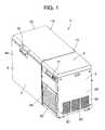
- FIG. 1 is a perspective view of a refrigeration apparatus 1 to which the present invention is applied
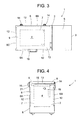
- FIG. 2 is a front view of the refrigeration apparatus 1
- FIG. 3 is a plan view of the refrigeration apparatus 1
- FIG. 4 is a side view in a state in which a storage chamber 4 is seen through the refrigeration apparatus 1
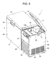
- FIG. 5 is a perspective view of the refrigeration apparatus 1 in a state in which a top panel 5 is opened.
- the refrigeration apparatus 1 of the present embodiment is suitable for storing, at an extremely low temperature, for example, a living tissue, a specimen or the like to be stored at a low temperature for a long time, and a main body of the apparatus is constituted of an insulating box body 2 which opens in an upper surface, and a mechanical chamber 3 which is positioned by the side of the insulating box body 2 and in which a compressor 10 and the like are installed.
- This insulating box body 2 is constituted of an outer box 6 made of a steel plate and an inner box 7 made of a satisfactorily thermally conductive metal such as aluminum, the boxes having opened upper surfaces.
- the insulating box body is also constituted of a breaker 8 connecting the upper ends of both the boxes 6, 7 to each other, and an insulating material 9 with which a space surrounded by the outer box 6, the inner box 7 and the breaker 8 is filled by an on-site foam system and which is made of a polyurethane resin.
- the inside of the inner box 7 is the storage chamber 4 having an open upper surface.
- a targeted temperature (hereinafter referred to as the in-chamber temperature) in the storage chamber 4 is set to, for example, -150°C or less. Therefore, the insulating box body 2 which separates the inside of the storage chamber 4 and outside air needs to have large insulating capability against a set low in-chamber temperature around 0°C. Therefore, to secure the insulating capability only by the insulating material 9 made of the polyurethane resin, the material has to be formed to be remarkably thick. There is also a problem that a sufficient storage amount in the storage chamber 4 cannot be secured with a limited main body dimension.
- vacuum insulating panels 12 made of glass wool are arranged in the inner wall surfaces of a front wall 6A of the outer box 6, a rear wall 6B and a side wall 6C positioned on a side opposite to a side provided with the mechanical chamber 3.
- the panels are tentatively fixed with an adhesive double coated tape, and then a space between both the boxes 6 and 7 is filled with the insulating material 9 by the on-site foam system.
- this vacuum insulating panel 12 glass wool having insulating properties is received in a container constituted of a multilayered film made of aluminum, a synthetic resin or the like which does not have any gas permeability. Afterward, air is discharged from the container by predetermined vacuum exhaust means, and an opening of the container is thermally sealed and joined. In consequence, since the vacuum insulating panel 12 has the insulating performance, the thickness dimension of the insulating material 9 is decreased as compared with a conventional example, but the same insulating effect can be obtained.
- an evaporator (an evaporation pipe) 62 constituting a refrigerant circuit of a cooling apparatus R described later in detail is attached to the peripheral surface of the inner box 7 on the insulating material 9 side in a heat exchange manner.
- the upper surface of the breaker 8 of the insulating box body 2 having the above constitution is formed in a staircase-like shape, and an insulating door 13 is provided on the surface via a packing (not shown) so that the insulating door is rotatable around one end, that is, the rear end of the door in the present embodiment by pivotable members 14, 14.
- the upper-surface opening of the storage chamber 4 is provided with an openable/closable inner lid 15 constituted of an insulating material.
- the lower surface of the insulating door 13 is provided with a pressing portion configured to protrude downwards.
- the pressing portion of the insulating door 13 presses the inner lid 15 to openably close the upper-surface opening of the storage chamber 4.
- the other end, that is, the front end of the insulating door 13 in the present embodiment is provided with a handle portion 16, and the handle portion 16 is operated to open or close the insulating door 13.
- a front panel 3A, a rear panel (not shown) and a side panel 3B constituting a side surface on a side opposite to a side provided with the insulating box body 2 form the mechanical chamber 3.
- the mechanical chamber 3 of the present embodiment is provided with a partition plate 17 which divides the inside of the chamber into upper and lower chambers.
- the compressor 10, a compressor 20 and the like constituting the cooling apparatus R as described above are received and installed under the partition plate 17, and the front panel 3A and the side panel 3B positioned under the partition plate 17 are provided with slits 3C for ventilation.
- An upper mechanical chamber 18 having an opened upper surface is constituted above the partition plate 17.
- the upper-surface opening of the upper mechanical chamber 18 is provided with the top panel 5 so that the panel is rotatable around one end, that is, the rear end of the panel in the present embodiment, whereby the upper mechanical chamber 18 is openably closed.
- a panel positioned on the front surface of the upper mechanical chamber 18 is an operation panel 21 for operating the refrigeration apparatus 1.
- a side surface constituting this upper mechanical chamber 18 on the insulating box body 2 side is provided with a measurement hole 19.
- This measurement hole 19 is extended through the outer box 6, the insulating material 9 and the inner box 7 constituting the insulating box body 2 so as to communicate with the storage chamber 4 formed in the insulating box body 2 provided adjacent to the measurement hole.
- a temperature sensor can be inserted into the storage chamber 4 from the outside, and a wiring line drawn from the temperature sensor is connected to an external recording apparatus main body through the measurement hole 19.
- a gap between this measurement hole 19 and the wiring line is closed by a plug 19A constituted of a sponge-like deformable special material having insulating properties. It is to be noted that the measurement hole 19 is closed by the plug 19A in an insulating manner in a state in which the temperature sensor is not attached to the hole.
- the top panel 5 provided in the mechanical chamber 3 is opened, and the measuring instrument can be inserted into the storage chamber 4 through the measurement hole 19 formed in the side surface of the insulating box body 2 positioned in the upper mechanical chamber 18. This can facilitate an operation of installing the measuring instrument in the storage chamber 4 cooled to a predetermined extremely low temperature.
- the measurement hole 19 of the present embodiment is formed in the side surface of the insulating box body 2 on the mechanical chamber 18 side. Therefore, even when the refrigeration apparatus 1 is installed adjacent to the wall of an installation environment such as the laboratory, or another device, a space necessary for using the measurement hole 19 does not especially have to be disposed. In consequence, an area required for installing the refrigeration apparatus 1 can be decreased, which is suitable for determining the layout of the laboratory or the like.
- the vacuum insulating panels 12 can be provided in the side surface other than the side surface adjacent to the mechanical chamber 3, that is, the front and rear walls and the side surface of the insulating box body 2 constituted so as to face the outside without influencing the forming position of the measurement hole 19. In consequence, the leakage of cold from the storage chamber 4 can be decreased, and the wasting of cooling energy can be suppressed.
- the insulating performance of the insulating box body 2 itself can be improved, and the dimension of an insulating wall can be decreased.
- a storage volume in the storage chamber 4 can be increased.
- the outer dimension can be decreased. Even in this case, the area required for installing the refrigeration apparatus 1 can be decreased.
- the measurement hole 19 of the present embodiment can be covered with the top panel 5 which can openably close the upper-surface opening of the upper mechanical chamber 18, whereby the appearance of the apparatus has a constitution in which the measurement hole 19 is not exposed, and the appearance can be improved. Moreover, when the top panel 5 is opened, an operation can easily be performed with respect to the measurement hole 19, and operability can be improved. When the partition plate 17 is removed, another device constituting the cooling apparatus R installed under the partition plate 17 can easily be operated, and the efficiency of a maintenance operation can be improved.
- the mechanical chamber 18 is closed with the top panel 5 in a case other than the case where the operation is performed with respect to the measurement hole 19, so that the top panel 5 can be used as a side table for an operation, and the panel is convenient for an operation of storing articles such as samples in the storage chamber 4 or taking the articles from the chamber.
- the measurement hole 19 is covered with the top panel 5 which closes the upper-surface opening of the upper mechanical chamber 18, but this is not restrictive, and a lid member for covering the measurement hole 19 or the like may be provided in the vicinity of the measurement hole 19.
- the refrigerant circuit of the refrigeration apparatus 1 in the present embodiment is constituted of a two-dimensional two-stage refrigerant circuit, as a multi-dimensional multistage refrigerant circuit, including independent refrigerant circuits of a high-temperature-side refrigerant circuit 25 as a first refrigerant circuit and a low-temperature-side refrigerant circuit 38 as a second refrigerant circuit.
- the compressor 10 constituting the high-temperature-side refrigerant circuit 25 is a reciprocating electromotive compressor using a one-phase or three-phase alternating-current power source, and a discharge side pipe 10D of the compressor 10 is connected to an auxiliary condenser 26.
- this auxiliary condenser 26 is connected to a refrigerant pipe 27 (hereinafter referred to as a frame pipe) arranged on the back side of this opening edge.
- this frame pipe 27 is connected to an oil cooler 29 of the compressor 10, and then connected to a condenser 28.
- the refrigerant pipe exiting from the condenser 28 is connected to an oil cooler 30 of the compressor 20 constituting the low-temperature-side refrigerant circuit 38, and is then connected to a condenser 31.
- the refrigerant pipe exiting from the condenser 31 is connected to an evaporator 34 as an evaporator portion constituting the evaporator successively via a drier 32 and a capillary tube 33 as a pressure reducing unit.
- An outlet side refrigerant pipe of the evaporator 34 is connected to an accumulator 35 as a refrigerant liquid reservoir, and the refrigerant pipe exiting from the accumulator 35 is connected to a suction side pipe 10S of the compressor 10.
- the auxiliary condenser 26 and the condensers 28 and 31 in the present embodiment are constituted as an integral condenser, and are cooled by a blower 36 for the condenser.
- the high-temperature-side refrigerant circuit 25 is filled with a refrigerant constituted of R407D and n-pentane as non-azeotropic refrigerants having different boiling points.
- R407D is constituted of R32 (difluoromethane: CH 2 F 2 ), R125 (pentafluoroethane: CHF 2 CF 3 ), and R134a (1,1,1,2-tetrafluoroethane: CH 2 FCF 3 ), and a composition includes 15 wt% of R32, 15 wt% of R125 and 70 wt% of R134a.
- R32 has -51.8°C
- R125 has -48.57°C
- R134a has -26.16°C.
- the boiling point of n-pentane is +36.1°C.
- the high-temperature gas refrigerant discharged from the compressor 10 is condensed, releases heat and is liquefied by the auxiliary condenser 26, the frame pipe 27, the oil cooler 29, the condenser 28, the oil cooler 30 of the compressor 20 of the low-temperature-side refrigerant circuit 38 and the condenser 31. Afterward, a water content contained in the refrigerant is removed by the drier 32, and the pressure of the refrigerant is reduced by the capillary tube 33. The refrigerants successively flow into the evaporator 34 to evaporate the refrigerants R32, R125 and R134a. Then, vaporization heat is absorbed from a surrounding area to cool the evaporator 34, and the refrigerant returns to the compressor 10 through the accumulator 35 as the refrigerant liquid reservoir.
- the compressor 10 has a capability of, for example, 1.5 HP, and the final reaching temperature of the evaporator 34 which is being operated is in a range of -27°C to -35°C.
- the refrigerant does not evaporate in the evaporator 34 and still has a liquid state. Therefore, the refrigerant hardly contributes to cooling, but the refrigerant has a function of feeding the lubricant of the compressor 10 and a mixed water content which cannot completely be absorbed by the drier 32 back to the compressor 10 in a state in which the same is dissolved in the refrigerant.
- the refrigerant also has a function of lowering the temperature of the compressor 10 by the evaporation of the liquid refrigerant in the compressor 10.
- the compressor 20 of the low-temperature-side refrigerant circuit 38 is a reciprocating electromotive compressor using a one-phase or three-phase alternating-current power source in the same manner as in the compressor 10, and a discharge side pipe 20D of the compressor 20 is connected to an oil separator 40 via a radiator 39 constituted of a wire condenser.
- This oil separator 40 is connected to an oil return tube 41 which returns to the compressor 20.
- a refrigerant pipe connected to the outlet side of the oil separator 40 is connected to a condensing pipe 42 as a high-pressure-side pipe inserted into the evaporator 34.
- This condensing pipe 42 constitutes a cascade heat exchanger 43 together with the evaporator 34.
- a discharge pipe connected to the outlet side of the condensing pipe 42 is connected to a first gas-liquid separator 46 via a drier 44.
- a gas-phase refrigerant separated by the gas-liquid separator 46 passes through the first intermediate heat exchanger 48 via a gas-phase pipe 47 to flow into a second gas-liquid separator 49.
- a liquid-phase refrigerant separated by the first gas-liquid separator 46 flows into the first intermediate heat exchanger 48 through a liquid-phase pipe 50, a drier 51 and a capillary tube 52 as a pressure reducing unit to evaporate the gas-phase refrigerant and cool the chamber.
- the liquid-phase refrigerant separated by the second gas-liquid separator 49 flows into a second intermediate heat exchanger 56 through a liquid-phase pipe 53, a drier 54 and a capillary tube 55 as a pressure reducing unit.
- the gas-phase refrigerant separated by the second gas-liquid separator 54 is cooled and liquefied while passing through a gas-phase pipe 57, the second intermediate heat exchanger 56 and third and fourth intermediate heat exchangers 58, 59, and the refrigerant flows into a capillary tube 61 as a pressure reducing unit through a pipe 68 and a drier 60.
- the capillary tube 61 is connected to an evaporation pipe 62 as an evaporator, and the evaporation pipe 62 is connected to the fourth intermediate heat exchanger 59 via a return pipe 69.
- the fourth intermediate heat exchanger 59 is successively connected to the third, second and first intermediate heat exchangers 58, 56 and 48, and then connected to a suction side pipe 20S of the compressor 20.
- the suction side pipe 20S is further connected to expansion tanks 65 as the tanks which store the refrigerant during the stop of the compressor 20 via a capillary tube 66 as a pressure reducing unit.
- the capillary tube 66 is connected in parallel with a check valve 67 in an expansion tank 65 direction as a forward direction.
- a non-azeotropic mixed refrigerant including R245fa, R600, R404A, R508, R14, R50 and R740 is introduced as a mixed refrigerant of seven types of refrigerants having different boiling points.
- R245fa is 1,1,1,-3,3-pentafluoropropane (CF 3 CH 2 CHF 2 ), and R600 is butane (CH 3 CH 2 CH 2 CH 3 ).
- R245fa has a boiling point of +15.3°C
- R600 has a boiling point of -0.5°C. Therefore, when these refrigerants are mixed at a predetermined ratio, the mixed refrigerant can be used as a substitute for heretofore used R21 having a boiling point of +8.9°C.
- R600 is a combustible substance.
- the refrigerant is introduced as an incombustible refrigerant in the refrigerant circuit 38.
- R245fa is set to 70 wt% with respect to a total weight of R245fa and R600. Above this value, the refrigerant becomes incombustible. Therefore, the weight percentage may be set to this value or more.
- R404A is constituted of R125 (pentafluoroethane: CHF 2 CF 3 ), R143a (1,1,1-trifluoroethane: CH 3 CF 3 ) and R134a (1,1,1,2-tetrafluoroethane: CH 2 FCF 3 ), and a composition includes 44 wt% of R125, 52 wt% of R143a and 4 wt% of R134a.
- the mixed refrigerant has a boiling point of -46.48°C. Therefore, the refrigerant can be used as a substitute for heretofore used R22 having a boiling point of -40.8°C.
- R508 is constituted of R23 (trifluoromethane: CHF 3 ) and R116 (hexafluoroethane: CF 3 CF 3 ), and a composition includes 39 wt% of R23 and 61 wt% of R116.
- the mixed refrigerant has a boiling point of -88.64°C.
- R14 is tetrafluoromethane (carbon tetrafluoride: CF 4 ), R50 is methane (CH 4 ) and R740 is argon (Ar).
- R14 has a boiling point of -127.9°C
- R50 has -161.5°C
- R740 has -185.86°C. It is to be noted that R50 might cause explosion when coupled with oxygen, but when R50 is mixed with R14, the danger of the explosion is eliminated. Therefore, even if a mixed refrigerant leakage accident occurs, any explosion is not generated.
- R245fa and R600, and R14 and R50 are beforehand mixed once in an incombustible state.
- the mixed refrigerant of R245fa and R600, R404A, R508A, the mixed refrigerant of R14 and R50, and R740 are beforehand mixed, and introduced into the refrigerant circuit.
- R245fa and R600, R404A, R5080A, R14 and R50, and R740 are introduced in this order from the refrigerant having the highest boiling point.
- composition of the refrigerants includes, for example, 10.3 wt% of the mixed refrigerant of R245fa and R600, 28 wt% of R404A, 29.2 wt% of R508A, 26.4 wt% of the mixed refrigerant of R14 and R50 and 5.1 wt% of R740.
- n-pentane in a range of 0.5 to 2 wt% with respect to the total weight of the non-azeotropic refrigerants
- R404A 4 wt% of n-pentane (in a range of 0.5 to 2 wt% with respect to the total weight of the non-azeotropic refrigerants) may be added to R404A.
- the high-temperature high-pressure gas mixed refrigerant discharged from the compressor 20 flows into the radiator 39 via the discharge side pipe 20D, and radiates heat in the radiator. Then, a part of n-pentane or R600 as an oil carrier refrigerant having a high boiling point and a satisfactory oil solubility in the mixed refrigerant is condensed and liquefied.
- the mixed refrigerant discharged from the radiator 39 flows into the oil separator 40, and a large part of lubricating oil of the compressor 20 mixed with the refrigerant and a part (a part of n-pentane or R600) of the refrigerant condensed and liquefied in the radiator 39 are fed back to the compressor 20 via the oil return tube 41.
- the refrigerant having higher purity and lower boiling point flows into the refrigerant circuit 38 after the cascade heat exchanger 43, and the extremely low temperature can efficiently be obtained. Therefore, even the compressors 10 and 20 having the same capability can cool the inside of the storage chamber 4 as a cooling target having a larger volume to a predetermined extremely low temperature, and the storage capacity can be increased without enlarging the whole refrigeration apparatus 1.
- the refrigerant fed into the oil separator 40 is once cooled in the radiator 39, and hence the temperature of the refrigerant flowing into the cascade heat exchanger 43 can be lowered.
- the temperature of the refrigerant fed into the cascade heat exchanger 43 has heretofore been about +65°C, but the temperature can be lowered to about +45°C in the present embodiment.
- a load to be applied to the compressor of the high-temperature-side refrigerant circuit 25 for cooling the refrigerant in the low-temperature-side refrigerant circuit 35 can be decreased.
- the load to be applied to the compressor 20 constituting the low-temperature-side refrigerant circuit 35 can be decreased. In consequence, the operation efficiency of the whole refrigeration apparatus 1 can be improved.
- Another mixed refrigerant itself is cooled to about -40°C to -30°C by the evaporator 34 in the cascade heat exchanger 43 to condense and liquefy a part of the refrigerants (a part of R245fa, R600, R404A and R508) having the high boiling point in the mixed refrigerant. Then, the mixed refrigerant discharged from the condensing pipe 42 of the cascade heat exchanger 43 flows into the first gas-liquid separator 46 through the drier 44.
- R14, R50 and R740 in the mixed refrigerant have a remarkably low boiling point, the refrigerants are not condensed yet, and have a gas state, and an only part of R245fa, R600, R404A and R508 is condensed and liquefied. Therefore, R14, R50 and R740 are separated to the gas-phase pipe 47, and R245fa, R600, R404A and R508 are separated to the liquid-phase pipe 50.
- the refrigerant mixture which has flowed into the gas-phase pipe 47 performs heat exchange between the mixture and the first intermediate heat exchanger 48, is condensed, and then reaches the second gas-liquid separator 49.
- the low-temperature refrigerant returning from the evaporation pipe 62 flows into the first intermediate heat exchanger 48.
- the liquid refrigerant which has flowed into the liquid-phase pipe 50 flows through the drier 51 to reach the capillary tube 52 where the pressure of the refrigerant is reduced. Afterward, the refrigerant flows into the first intermediate heat exchanger 48 to evaporate in the exchanger, thereby contributing to the cooling.
- the first intermediate heat exchanger 48 has an intermediate temperature of about -60°C. Therefore, R508 in the mixed refrigerant which has passed through the gas-phase pipe 47 is completely condensed and liquefied, and branched to the second gas-liquid separator 49.
- R14, R50 and R740 have a lower boiling point, and hence still have a gas state.
- the drier 54 removes the water content from R508 branched by the second gas-liquid separator 49, and the pressure of the refrigerant is reduced by the capillary tube 55. Afterward, the refrigerant flows into the second intermediate heat exchanger 56, R14, R50 and R740 in the gas-phase pipe 57 are cooled together with the low-temperature refrigerant returning from the evaporation pipe 62, and R14 having the highest evaporation temperature among these refrigerants is condensed. In consequence, the second intermediate heat exchanger 56 has an intermediate temperature of about -90°C.
- the gas-phase pipe 57 passing through this second intermediate heat exchanger 56 subsequently passes through the third intermediate heat exchanger 58 and the fourth intermediate heat exchanger 59.
- the refrigerant immediately discharged from the evaporation pipe 62 is fed back to the fourth intermediate heat exchanger 59.
- the fourth intermediate heat exchanger 59 reaches a considerably low intermediate temperature of about -130°C.
- the refrigerants still having a gas phase state are successively condensed in the intermediate heat exchangers 48, 56, 58 and 59 by use of an evaporation temperature difference between the refrigerants in the low-temperature-side refrigerant circuit 38, and an extremely low temperature of -150°C or less can be achieved in the evaporation pipe 42 as a final stage. Therefore, the evaporation pipe 62 is wound along the insulating material 9 side of the inner box 6 in a heat exchange manner, so that an in-chamber temperature of -152°C or less can be realized in the storage chamber 4 of the refrigeration apparatus 1.
- the refrigerant discharged from the evaporation pipe 62 successively flows into the fourth intermediate heat exchanger 59, the third intermediate heat exchanger 58, the second intermediate heat exchanger 56 and the first intermediate heat exchanger 48, and the refrigerant joins the refrigerants evaporated in the respective heat exchangers, and returns the compressor 20 via the suction side pipe 20S.
- a large part of the oil mixed with the refrigerant and discharged from the compressor 20 is separated by the oil separator 40 and returned to the compressor 20.
- the mist-like oil discharged from the oil separator 40 together with the refrigerant is returned to the compressor 20 in a state in which the oil is dissolved in R600 having high oil solubility. In consequence, the lubricating defect of the compressor 20, or locking can be prevented.
- R600 returns the compressor 20 while maintaining the liquid state, and is evaporated in this compressor 20, so that the discharge temperature of the compressor 20 can be lowered.
- the compressor 20 constituting the low-temperature-side refrigerant circuit 38 having the above constitution is subjected to ON-OFF control by a controller (not shown) based on the in-chamber temperature of the storage chamber 4.
- a controller not shown
- the mixed refrigerant in the low-temperature-side refrigerant circuit 38 is collected in the expansion tank 65 via the check valve 67 having the expansion tank 65 direction as the forward direction.
- the refrigerant in the refrigerant circuit 38 can remarkably quickly be collected in the expansion tank 65 via the check valve 67.
- the rise of the pressure in the refrigerant circuit 38 can be prevented.
- the compressor 20 is started by the controller, the refrigerant is gradually returned from the expansion tank 65 to the refrigerant circuit 38 via the capillary tube 66, and the starting load of the compressor 20 can be decreased.
- the refrigerant circuit constituting the refrigeration apparatus 1 is constituted of the high-temperature-side refrigerant circuit 25 and the low-temperature-side refrigerant circuit 38 constituting independent refrigerant closed circuits so that the refrigerant discharged from the compressor 10 or 20 is condensed and evaporated to exert a cooling function.
- the low-temperature-side refrigerant circuit 38 has the compressor 20, the condensing pipe 42, the evaporation pipe 62, a plurality of, specifically four intermediate heat exchangers 48, 56, 58 and 59 connected in series so that the refrigerant fed back from this evaporation pipe 62 circulates, and a plurality of, specifically three capillary tubes 42, 55 and 61.
- a plurality of types of non-azeotropic mixed refrigerants are introduced, and the condensed refrigerant in the refrigerants fed through the condensing pipe 42 is allowed to join each intermediate heat exchanger via each capillary tube.
- the non-condensed refrigerant in the refrigerants is cooled by the intermediate heat exchanger, and the refrigerant having a lower boiling point is successively condensed.
- the refrigerant having the lowest boiling point is allowed to flow into the evaporation pipe 62 via the final-stage capillary tube 61.
- the evaporator 34 of the high-temperature-side refrigerant circuit 25 and the condensing pipe 42 of the low-temperature-side refrigerant circuit 38 constitute the cascade heat exchanger 43, and the extremely low temperature is obtained in the evaporation pipe 42 of the low-temperature-side refrigerant circuit 38.
- the present invention is not limited to this apparatus.
- a refrigeration apparatus of a simple multi-dimensional (two-dimensional) system which includes a high-temperature-side refrigerant circuit and a low-temperature-side refrigerant circuit constituting independent refrigerant closed circuits where refrigerants discharged from compressors are condensed and then evaporated to exert a cooling function and in which an evaporator of the high-temperature-side refrigerant circuit and a condenser of the low-temperature-side refrigerant circuit constitute a cascade heat exchanger to obtain an extremely low temperature in an evaporator of the low-temperature-side refrigerant circuit, a similar effect can be obtained.
Abstract
Description
- The present invention relates to a refrigeration apparatus including a refrigerant circuit in which a refrigerant discharged from a compressor is condensed and then evaporated to exert a cooling function.
- Heretofore, a refrigeration apparatus using a compressor has been constituted of a refrigerant circuit in which the compressor, a condenser, a capillary tube (a pressure reducing unit) and an evaporator are annularly connected to one another via pipes. A predetermined refrigerant is introduced in this refrigerant circuit.
When the compressor is operated, a high-temperature gas refrigerant discharged from the compressor is condensed in the condenser, radiates heat and is liquefied. Afterward, the pressure of the refrigerant is reduced by the capillary tube, and the refrigerant flows into the evaporator to evaporate, absorbs vaporization heat from a surrounding area to cool the evaporator, and returns to the compressor. - Here, a suction side pipe of the compressor is connected, via the pressure reducing unit, to a tank (hereinafter referred to as the expansion tank) which stores the refrigerant introduced in the refrigerant circuit during the stop of the compressor. In consequence, an equilibrium pressure in the refrigerant circuit during the stop of the compressor is lowered to facilitate the operation of the compressor during the stop of the compressor (see Japanese Patent Application Laid-Open No.
62-73046 - However, since the expansion tank is provided with the pressure reducing unit as described above, the following problems occur. It is difficult to quickly collect the refrigerant of the refrigerant circuit in the expansion tank during the stop of the compressor, and much time is required for achieving the equilibrium pressure in the refrigerant circuit. Therefore, in a case where the compressor is restarted in a state in which the refrigerant circuit has a high pressure, a load to be applied to the compressor increases. Consequently, in a case where the compressor is not restarted until the equilibrium pressure is achieved, the operation ratio of the compressor lowers, and a very long time is required for performing a pull-down operation at a time when a power source of the refrigeration apparatus turns on.
- The present invention has been developed to solve conventional technical problems, and an object thereof is to provide a refrigeration apparatus capable of quickly collecting, in an expansion tank, a refrigerant in a refrigerant circuit during the stop of a compressor and capable of decreasing a load to be applied to the compressor during restart.
- A refrigeration apparatus of the present invention is characterized by comprising: a refrigerant circuit in which a refrigerant discharged from a compressor is condensed and then evaporated to exert a cooling function; and a tank connected to a pipe of the compressor on a suction side via a pressure reducing unit, the pressure reducing unit being connected in parallel with a check valve, the direction of the tank being the forward direction of the check valve.
- A refrigeration apparatus of the invention of a second aspect is characterized by comprising: a high-temperature-side refrigerant circuit and a low-temperature-side refrigerant circuit each constituting an independent refrigerant closed circuit in which a refrigerant discharged from a compressor is condensed and then evaporated to exert a cooling function, an evaporator of the high-temperature-side refrigerant circuit and a condenser of the low-temperature-side refrigerant circuit constituting a cascade heat exchanger, an evaporator of the low-temperature-side refrigerant circuit achieving an extremely low temperature; and a tank connected to a pipe of the compressor of the low-temperature-side refrigerant circuit on a suction side via a pressure reducing unit, the pressure reducing unit being connected in parallel with a check valve, the direction of the tank being the forward direction of the check valve.
- A refrigeration apparatus of the invention of a third aspect is characterized by comprising: a compressor, a condenser, an evaporator, and a plurality of intermediate heat exchangers and a plurality of pressure reducing units connected in series so that a refrigerant fed back from the evaporator circulates, wherein a plurality of types of non-azeotropic mixed refrigerants are introduced, a condensed refrigerant in the refrigerants fed through the condenser is allowed to join the intermediate heat exchanger via the pressure reducing unit, and a non-condensed refrigerant in the refrigerants is cooled by the intermediate heat exchanger to successively condense the refrigerant having a lower boiling point, and the refrigerant having the lowest boiling point is allowed to flow into the evaporator via the final-stage pressure reducing unit to obtain an extremely low temperature, the refrigeration apparatus further comprising: a tank connected to a pipe of the compressor on a suction side via the pressure reducing unit, the pressure reducing unit being connected in parallel with a check valve, the direction of the tank being the forward direction of the check valve.
- A refrigeration apparatus of the invention of a fourth aspect is characterized by comprising: a high-temperature-side refrigerant circuit and a low-temperature-side refrigerant circuit each constituting an independent refrigerant closed circuit in which a refrigerant discharged from a compressor is condensed and then evaporated to exert a cooling function, the low-temperature-side refrigerant circuit having the compressor, a condenser, an evaporator, and a plurality of intermediate heat exchangers and a plurality of pressure reducing units connected in series so that the refrigerant fed back from the evaporator circulates, wherein a plurality of types of non-azeotropic mixed refrigerants are introduced, a condensed refrigerant in the refrigerants fed through the condenser is allowed to join the intermediate heat exchanger via the pressure reducing unit, a non-condensed refrigerant in the refrigerants is cooled by the intermediate heat exchanger to successively condense the refrigerant having a lower boiling point, the refrigerant having the lowest boiling point is allowed to flow into the evaporator via the final-stage pressure reducing unit, an evaporator of the high-temperature-side refrigerant circuit and the condenser of the low-temperature-side refrigerant circuit constitute a cascade heat exchanger, and the evaporator of the low-temperature-side refrigerant circuit obtains an extremely low temperature, the refrigeration apparatus further comprising: a tank connected to a pipe of the compressor of the low-temperature-side refrigerant circuit on a suction side via the pressure reducing unit, the pressure reducing unit being connected in parallel with a check valve, the direction of the tank being the forward direction of the check valve.
- According to the present invention, the refrigeration apparatus comprises the refrigerant circuit in which the refrigerant discharged from the compressor is condensed and then evaporated to exert the cooling function, and the tank connected to the pipe of the compressor on the suction side via the pressure reducing unit, the pressure reducing unit being connected in parallel with the check valve, the direction of the tank being the forward direction of the check valve. In consequence, during the stop of the compressor, the refrigerant in the refrigerant circuit can quickly be collected in the tank via the check valve.
- Consequently, the rise of a pressure in the refrigerant circuit can be prevented. In a case where after the start of the compressor, the refrigerant is gradually returned from the tank to the refrigerant circuit, the starting load of the compressor can be decreased.
- Therefore, when the refrigerant is quickly collected in the tank during the stop of the compressor, an equilibrium pressure in the refrigerant circuit can quickly be achieved. During the restart of the compressor, the compressor can smoothly be restarted without applying any load to the compressor. In consequence, the operation efficiency of the compressor can be improved. For example, time required for a pull-down operation can be shortened to improve convenience.
- According to the invention of the second aspect, the refrigeration apparatus comprises the high-temperature-side refrigerant circuit and the low-temperature-side refrigerant circuit each constituting the independent refrigerant closed circuit in which the refrigerant discharged from the compressor is condensed and then evaporated to exert the cooling function, the evaporator of the high-temperature-side refrigerant circuit and the condenser of the low-temperature-side refrigerant circuit constituting the cascade heat exchanger, the evaporator of the low-temperature-side refrigerant circuit achieving the extremely low temperature. The refrigeration apparatus further comprises the tank connected to the pipe of the compressor of the low-temperature-side refrigerant circuit on the suction side via the pressure reducing unit, the pressure reducing unit is connected in parallel with the check valve, and the direction of the tank is the forward direction of the check valve. Consequently, in a simple multi-dimensional refrigerant circuit, the refrigerant in the low-temperature-side refrigerant circuit can quickly be collected in the tank via the check valve during the stop of the compressor of the low-temperature-side refrigerant circuit.
- In consequence, the rise of the pressure in the low-temperature-side refrigerant circuit can be prevented. In a case where after the start of the compressor, the refrigerant is gradually returned from the tank to the low-temperature-side refrigerant circuit via the pressure reducing unit, the starting load of the compressor can be decreased.
- Therefore, when the refrigerant is quickly collected in the tank during the stop of the compressor, the equilibrium pressure in the low-temperature-side refrigerant circuit can quickly be achieved. During the restart of the compressor, the compressor can smoothly be restarted without applying any load to the compressor. In consequence, the operation efficiency of the compressor can be improved. For example, the time required for the pull-down operation can be shortened to improve the convenience.
- According to the invention of the third aspect, the refrigeration apparatus comprises the compressor, the condenser, the evaporator, the plurality of intermediate heat exchangers and the plurality of pressure reducing units connected in series so that the refrigerant fed back from the evaporator circulates, wherein the plurality of types of non-azeotropic mixed refrigerants are introduced, the condensed refrigerant in the refrigerants fed through the condenser is allowed to join the intermediate heat exchanger via the pressure reducing unit, and the non-condensed refrigerant in the refrigerants is cooled by the intermediate heat exchanger to successively condense the refrigerant having the lower boiling point, and the refrigerant having the lowest boiling point is allowed to flow into the evaporator via the final-stage pressure reducing unit to obtain the extremely low temperature. The refrigeration apparatus further comprises the tank connected to the pipe of the compressor on the suction side via the pressure reducing unit, the pressure reducing unit is connected in parallel with the check valve, and the direction of the tank is the forward direction of the check valve. Consequently, in a simple multi-stage refrigerant circuit, the refrigerant in the refrigerant circuit can quickly be collected in the tank via the check valve during the stop of the compressor of the refrigerant circuit.
- Consequently, the rise of the pressure in the refrigerant circuit can be prevented. In a case where after the start of the compressor, the refrigerant is gradually returned from the tank to the refrigerant circuit, the starting load of the compressor can be decreased.
- Therefore, when the refrigerant is quickly collected in the tank during the stop of the compressor, the equilibrium pressure in the refrigerant circuit can quickly be achieved. During the restart of the compressor, the compressor can smoothly be restarted without applying any load to the compressor. In consequence, the operation efficiency of the compressor can be improved. For example, the time required for the pull-down operation can be shortened to improve the convenience.
- According to the invention of the fourth aspect, the refrigeration apparatus comprises the high-temperature-side refrigerant circuit and the low-temperature-side refrigerant circuit each constituting the independent refrigerant closed circuit in which the refrigerant discharged from the compressor is condensed and then evaporated to exert the cooling function. The low-temperature-side refrigerant circuit has the compressor, the condenser, the evaporator, and the plurality of intermediate heat exchangers and the plurality of pressure reducing units connected in series so that the refrigerant fed back from the evaporator circulates, wherein the plurality of types of non-azeotropic mixed refrigerants are introduced, the condensed refrigerant in the refrigerants fed through the condenser is allowed to join the intermediate heat exchanger via the pressure reducing unit, the non-condensed refrigerant in the refrigerants is cooled by the intermediate heat exchanger to successively condense the refrigerant having the lower boiling point, the refrigerant having the lowest boiling point is allowed to flow into the evaporator via the final-stage pressure reducing unit, the evaporator of the high-temperature-side refrigerant circuit and the condenser of the low-temperature-side refrigerant circuit constitute the cascade heat exchanger, and the evaporator of the low-temperature-side refrigerant circuit obtains the extremely low temperature. The refrigeration apparatus further comprises the tank connected to the pipe of the compressor of the low-temperature-side refrigerant circuit on the suction side via the pressure reducing unit, the pressure reducing unit is connected in parallel with the check valve, and the direction of the tank is the forward direction of the check valve. Consequently, in a multi-dimensional multi-stage refrigeration apparatus, during the stop of the compressor of the low-temperature-side refrigerant circuit, the refrigerant in the low-temperature-side refrigerant circuit can quickly be collected in the tank via the check valve.
- In consequence, the rise of the pressure in the low-temperature-side refrigerant circuit can be prevented. In a case where after the start of the compressor, the refrigerant is gradually returned from the tank to the low-temperature-side refrigerant circuit, the starting load of the compressor can be decreased.
- Therefore, when the refrigerant is quickly collected in the tank during the stop of the compressor, the equilibrium pressure in the low-temperature-side refrigerant circuit can quickly be achieved. During the restart of the compressor, the compressor can smoothly be restarted without applying any load to the compressor. In consequence, the operation efficiency of the compressor can be improved. For example, the time required for the pull-down operation can be shortened to improve the convenience.
-
-
FIG. 1 is a perspective view of a refrigeration apparatus to which the present invention is applied; -
FIG. 2 is a front view of the refrigeration apparatus ofFIG. 1 ; -
FIG. 3 is a plan view of the refrigeration apparatus ofFIG. 1 ; -
FIG. 4 is a side view in a state in which a storage chamber is seen through the refrigeration apparatus ofFIG. 1 ; -
FIG. 5 is a perspective view of the refrigeration apparatus in a state in which a top panel is opened; and -
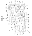
FIG. 6 is a refrigerant circuit diagram of the refrigeration apparatus ofFIG. 1 . - An embodiment of the present invention will hereinafter be described with reference to the drawings.
FIG. 1 is a perspective view of arefrigeration apparatus 1 to which the present invention is applied,FIG. 2 is a front view of therefrigeration apparatus 1,FIG. 3 is a plan view of therefrigeration apparatus 1,FIG. 4 is a side view in a state in which astorage chamber 4 is seen through therefrigeration apparatus 1, andFIG. 5 is a perspective view of therefrigeration apparatus 1 in a state in which atop panel 5 is opened. Therefrigeration apparatus 1 of the present embodiment is suitable for storing, at an extremely low temperature, for example, a living tissue, a specimen or the like to be stored at a low temperature for a long time, and a main body of the apparatus is constituted of aninsulating box body 2 which opens in an upper surface, and amechanical chamber 3 which is positioned by the side of theinsulating box body 2 and in which acompressor 10 and the like are installed. - This insulating
box body 2 is constituted of anouter box 6 made of a steel plate and aninner box 7 made of a satisfactorily thermally conductive metal such as aluminum, the boxes having opened upper surfaces. The insulating box body is also constituted of abreaker 8 connecting the upper ends of both theboxes material 9 with which a space surrounded by theouter box 6, theinner box 7 and thebreaker 8 is filled by an on-site foam system and which is made of a polyurethane resin. The inside of theinner box 7 is thestorage chamber 4 having an open upper surface. - In the present embodiment, a targeted temperature (hereinafter referred to as the in-chamber temperature) in the
storage chamber 4 is set to, for example, -150°C or less. Therefore, the insulatingbox body 2 which separates the inside of thestorage chamber 4 and outside air needs to have large insulating capability against a set low in-chamber temperature around 0°C. Therefore, to secure the insulating capability only by the insulatingmaterial 9 made of the polyurethane resin, the material has to be formed to be remarkably thick. There is also a problem that a sufficient storage amount in thestorage chamber 4 cannot be secured with a limited main body dimension. - To solve the problem, in the insulating
box body 2 of the present embodiment,vacuum insulating panels 12 made of glass wool are arranged in the inner wall surfaces of afront wall 6A of theouter box 6, arear wall 6B and aside wall 6C positioned on a side opposite to a side provided with themechanical chamber 3. The panels are tentatively fixed with an adhesive double coated tape, and then a space between both theboxes material 9 by the on-site foam system. - To constitute this
vacuum insulating panel 12, glass wool having insulating properties is received in a container constituted of a multilayered film made of aluminum, a synthetic resin or the like which does not have any gas permeability. Afterward, air is discharged from the container by predetermined vacuum exhaust means, and an opening of the container is thermally sealed and joined. In consequence, since thevacuum insulating panel 12 has the insulating performance, the thickness dimension of the insulatingmaterial 9 is decreased as compared with a conventional example, but the same insulating effect can be obtained. - On the other hand, an evaporator (an evaporation pipe) 62 constituting a refrigerant circuit of a cooling apparatus R described later in detail is attached to the peripheral surface of the
inner box 7 on the insulatingmaterial 9 side in a heat exchange manner. - Moreover, as shown in
FIGS. 2 and4 , the upper surface of thebreaker 8 of the insulatingbox body 2 having the above constitution is formed in a staircase-like shape, and an insulatingdoor 13 is provided on the surface via a packing (not shown) so that the insulating door is rotatable around one end, that is, the rear end of the door in the present embodiment bypivotable members storage chamber 4 is provided with an openable/closableinner lid 15 constituted of an insulating material. Moreover, the lower surface of the insulatingdoor 13 is provided with a pressing portion configured to protrude downwards. In consequence, the pressing portion of the insulatingdoor 13 presses theinner lid 15 to openably close the upper-surface opening of thestorage chamber 4. Moreover, the other end, that is, the front end of the insulatingdoor 13 in the present embodiment is provided with ahandle portion 16, and thehandle portion 16 is operated to open or close the insulatingdoor 13. - On the other hand, by the side of the insulating
box body 2, afront panel 3A, a rear panel (not shown) and aside panel 3B constituting a side surface on a side opposite to a side provided with the insulatingbox body 2 form themechanical chamber 3. Themechanical chamber 3 of the present embodiment is provided with apartition plate 17 which divides the inside of the chamber into upper and lower chambers. Thecompressor 10, acompressor 20 and the like constituting the cooling apparatus R as described above are received and installed under thepartition plate 17, and thefront panel 3A and theside panel 3B positioned under thepartition plate 17 are provided withslits 3C for ventilation. - An upper
mechanical chamber 18 having an opened upper surface is constituted above thepartition plate 17. The upper-surface opening of the uppermechanical chamber 18 is provided with thetop panel 5 so that the panel is rotatable around one end, that is, the rear end of the panel in the present embodiment, whereby the uppermechanical chamber 18 is openably closed. It is to be noted that a panel positioned on the front surface of the uppermechanical chamber 18 is anoperation panel 21 for operating therefrigeration apparatus 1. - A side surface constituting this upper
mechanical chamber 18 on the insulatingbox body 2 side is provided with ameasurement hole 19. Thismeasurement hole 19 is extended through theouter box 6, the insulatingmaterial 9 and theinner box 7 constituting the insulatingbox body 2 so as to communicate with thestorage chamber 4 formed in the insulatingbox body 2 provided adjacent to the measurement hole. Through themeasurement hole 19, a temperature sensor can be inserted into thestorage chamber 4 from the outside, and a wiring line drawn from the temperature sensor is connected to an external recording apparatus main body through themeasurement hole 19. Moreover, a gap between thismeasurement hole 19 and the wiring line is closed by aplug 19A constituted of a sponge-like deformable special material having insulating properties. It is to be noted that themeasurement hole 19 is closed by theplug 19A in an insulating manner in a state in which the temperature sensor is not attached to the hole. - In consequence, when an instrument for measuring or recording the temperature in the
storage chamber 4 is used, thetop panel 5 provided in themechanical chamber 3 is opened, and the measuring instrument can be inserted into thestorage chamber 4 through themeasurement hole 19 formed in the side surface of the insulatingbox body 2 positioned in the uppermechanical chamber 18. This can facilitate an operation of installing the measuring instrument in thestorage chamber 4 cooled to a predetermined extremely low temperature. - In particular, unlike a measurement hole provided in a conventional refrigeration apparatus, the
measurement hole 19 of the present embodiment is formed in the side surface of the insulatingbox body 2 on themechanical chamber 18 side. Therefore, even when therefrigeration apparatus 1 is installed adjacent to the wall of an installation environment such as the laboratory, or another device, a space necessary for using themeasurement hole 19 does not especially have to be disposed. In consequence, an area required for installing therefrigeration apparatus 1 can be decreased, which is suitable for determining the layout of the laboratory or the like. - Moreover, since the
measurement hole 19 is formed in the wall surface of the insulatingbox body 2 on a side adjacent to themechanical chamber 3, thevacuum insulating panels 12 can be provided in the side surface other than the side surface adjacent to themechanical chamber 3, that is, the front and rear walls and the side surface of the insulatingbox body 2 constituted so as to face the outside without influencing the forming position of themeasurement hole 19. In consequence, the leakage of cold from thestorage chamber 4 can be decreased, and the wasting of cooling energy can be suppressed. - Therefore, even when the inside of the
storage chamber 4 has an extremely low temperature of, for example, -150°C or less as in the present embodiment, the insulating performance of the insulatingbox body 2 itself can be improved, and the dimension of an insulating wall can be decreased. Even when the refrigeration apparatus has an outer dimension similar to that in a conventional example, a storage volume in thestorage chamber 4 can be increased. Alternatively, even when the refrigeration apparatus has the storage volume similar to that in the conventional example, the outer dimension can be decreased. Even in this case, the area required for installing therefrigeration apparatus 1 can be decreased. - Furthermore, the
measurement hole 19 of the present embodiment can be covered with thetop panel 5 which can openably close the upper-surface opening of the uppermechanical chamber 18, whereby the appearance of the apparatus has a constitution in which themeasurement hole 19 is not exposed, and the appearance can be improved. Moreover, when thetop panel 5 is opened, an operation can easily be performed with respect to themeasurement hole 19, and operability can be improved. When thepartition plate 17 is removed, another device constituting the cooling apparatus R installed under thepartition plate 17 can easily be operated, and the efficiency of a maintenance operation can be improved. Themechanical chamber 18 is closed with thetop panel 5 in a case other than the case where the operation is performed with respect to themeasurement hole 19, so that thetop panel 5 can be used as a side table for an operation, and the panel is convenient for an operation of storing articles such as samples in thestorage chamber 4 or taking the articles from the chamber. - It is to be noted that in the present embodiment, the
measurement hole 19 is covered with thetop panel 5 which closes the upper-surface opening of the uppermechanical chamber 18, but this is not restrictive, and a lid member for covering themeasurement hole 19 or the like may be provided in the vicinity of themeasurement hole 19. - Next, the refrigerant circuit of the
refrigeration apparatus 1 of the present embodiment will be described with reference toFIG. 6 . The refrigerant circuit of therefrigeration apparatus 1 in the present embodiment is constituted of a two-dimensional two-stage refrigerant circuit, as a multi-dimensional multistage refrigerant circuit, including independent refrigerant circuits of a high-temperature-side refrigerant circuit 25 as a first refrigerant circuit and a low-temperature-side refrigerant circuit 38 as a second refrigerant circuit. - The
compressor 10 constituting the high-temperature-side refrigerant circuit 25 is a reciprocating electromotive compressor using a one-phase or three-phase alternating-current power source, and adischarge side pipe 10D of thecompressor 10 is connected to anauxiliary condenser 26. To heat astorage chamber 4 opening edge and prevent dew condensation, thisauxiliary condenser 26 is connected to a refrigerant pipe 27 (hereinafter referred to as a frame pipe) arranged on the back side of this opening edge. Moreover, thisframe pipe 27 is connected to an oil cooler 29 of thecompressor 10, and then connected to acondenser 28. Furthermore, the refrigerant pipe exiting from thecondenser 28 is connected to an oil cooler 30 of thecompressor 20 constituting the low-temperature-side refrigerant circuit 38, and is then connected to acondenser 31. The refrigerant pipe exiting from thecondenser 31 is connected to anevaporator 34 as an evaporator portion constituting the evaporator successively via a drier 32 and acapillary tube 33 as a pressure reducing unit. An outlet side refrigerant pipe of theevaporator 34 is connected to anaccumulator 35 as a refrigerant liquid reservoir, and the refrigerant pipe exiting from theaccumulator 35 is connected to asuction side pipe 10S of thecompressor 10. It is to be noted that theauxiliary condenser 26 and thecondensers blower 36 for the condenser. - The high-temperature-
side refrigerant circuit 25 is filled with a refrigerant constituted of R407D and n-pentane as non-azeotropic refrigerants having different boiling points. R407D is constituted of R32 (difluoromethane: CH2F2), R125 (pentafluoroethane: CHF2CF3), and R134a (1,1,1,2-tetrafluoroethane: CH2FCF3), and a composition includes 15 wt% of R32, 15 wt% of R125 and 70 wt% of R134a. As to the boiling points of the refrigerants, R32 has -51.8°C, R125 has -48.57°C and R134a has -26.16°C. Moreover, the boiling point of n-pentane is +36.1°C. - The high-temperature gas refrigerant discharged from the
compressor 10 is condensed, releases heat and is liquefied by theauxiliary condenser 26, theframe pipe 27, theoil cooler 29, thecondenser 28, theoil cooler 30 of thecompressor 20 of the low-temperature-side refrigerant circuit 38 and thecondenser 31. Afterward, a water content contained in the refrigerant is removed by the drier 32, and the pressure of the refrigerant is reduced by thecapillary tube 33. The refrigerants successively flow into theevaporator 34 to evaporate the refrigerants R32, R125 and R134a. Then, vaporization heat is absorbed from a surrounding area to cool the evaporator 34, and the refrigerant returns to thecompressor 10 through theaccumulator 35 as the refrigerant liquid reservoir. - At this time, the
compressor 10 has a capability of, for example, 1.5 HP, and the final reaching temperature of theevaporator 34 which is being operated is in a range of -27°C to -35°C. At such a low temperature, since n-pentane of the refrigerant has a boiling point of +36.1°C, the refrigerant does not evaporate in theevaporator 34 and still has a liquid state. Therefore, the refrigerant hardly contributes to cooling, but the refrigerant has a function of feeding the lubricant of thecompressor 10 and a mixed water content which cannot completely be absorbed by the drier 32 back to thecompressor 10 in a state in which the same is dissolved in the refrigerant. The refrigerant also has a function of lowering the temperature of thecompressor 10 by the evaporation of the liquid refrigerant in thecompressor 10. - On the other hand, the
compressor 20 of the low-temperature-side refrigerant circuit 38 is a reciprocating electromotive compressor using a one-phase or three-phase alternating-current power source in the same manner as in thecompressor 10, and adischarge side pipe 20D of thecompressor 20 is connected to anoil separator 40 via aradiator 39 constituted of a wire condenser. Thisoil separator 40 is connected to anoil return tube 41 which returns to thecompressor 20. A refrigerant pipe connected to the outlet side of theoil separator 40 is connected to a condensingpipe 42 as a high-pressure-side pipe inserted into theevaporator 34. This condensingpipe 42 constitutes acascade heat exchanger 43 together with theevaporator 34. - Moreover, a discharge pipe connected to the outlet side of the condensing
pipe 42 is connected to a first gas-liquid separator 46 via a drier 44. A gas-phase refrigerant separated by the gas-liquid separator 46 passes through the firstintermediate heat exchanger 48 via a gas-phase pipe 47 to flow into a second gas-liquid separator 49. A liquid-phase refrigerant separated by the first gas-liquid separator 46 flows into the firstintermediate heat exchanger 48 through a liquid-phase pipe 50, a drier 51 and acapillary tube 52 as a pressure reducing unit to evaporate the gas-phase refrigerant and cool the chamber. - The liquid-phase refrigerant separated by the second gas-
liquid separator 49 flows into a secondintermediate heat exchanger 56 through a liquid-phase pipe 53, a drier 54 and acapillary tube 55 as a pressure reducing unit. The gas-phase refrigerant separated by the second gas-liquid separator 54 is cooled and liquefied while passing through a gas-phase pipe 57, the secondintermediate heat exchanger 56 and third and fourthintermediate heat exchangers capillary tube 61 as a pressure reducing unit through apipe 68 and a drier 60. Thecapillary tube 61 is connected to anevaporation pipe 62 as an evaporator, and theevaporation pipe 62 is connected to the fourthintermediate heat exchanger 59 via areturn pipe 69. - The fourth
intermediate heat exchanger 59 is successively connected to the third, second and firstintermediate heat exchangers suction side pipe 20S of thecompressor 20. Thesuction side pipe 20S is further connected toexpansion tanks 65 as the tanks which store the refrigerant during the stop of thecompressor 20 via acapillary tube 66 as a pressure reducing unit. Thecapillary tube 66 is connected in parallel with acheck valve 67 in anexpansion tank 65 direction as a forward direction. - In the low-temperature-
side refrigerant circuit 38, a non-azeotropic mixed refrigerant including R245fa, R600, R404A, R508, R14, R50 and R740 is introduced as a mixed refrigerant of seven types of refrigerants having different boiling points. R245fa is 1,1,1,-3,3-pentafluoropropane (CF3CH2CHF2), and R600 is butane (CH3CH2CH2CH3). R245fa has a boiling point of +15.3°C, and R600 has a boiling point of -0.5°C. Therefore, when these refrigerants are mixed at a predetermined ratio, the mixed refrigerant can be used as a substitute for heretofore used R21 having a boiling point of +8.9°C. - It is to be noted that R600 is a combustible substance. When R600 is mixed with incombustible R245fa at a predetermined ratio, that is, R245fa/R600:70/30 in the present embodiment, the refrigerant is introduced as an incombustible refrigerant in the
refrigerant circuit 38. It is to be noted that in the present embodiment, R245fa is set to 70 wt% with respect to a total weight of R245fa and R600. Above this value, the refrigerant becomes incombustible. Therefore, the weight percentage may be set to this value or more. - R404A is constituted of R125 (pentafluoroethane: CHF2CF3), R143a (1,1,1-trifluoroethane: CH3CF3) and R134a (1,1,1,2-tetrafluoroethane: CH2FCF3), and a composition includes 44 wt% of R125, 52 wt% of R143a and 4 wt% of R134a. The mixed refrigerant has a boiling point of -46.48°C. Therefore, the refrigerant can be used as a substitute for heretofore used R22 having a boiling point of -40.8°C.
- R508 is constituted of R23 (trifluoromethane: CHF3) and R116 (hexafluoroethane: CF3CF3), and a composition includes 39 wt% of R23 and 61 wt% of R116. The mixed refrigerant has a boiling point of -88.64°C.
- Moreover, R14 is tetrafluoromethane (carbon tetrafluoride: CF4), R50 is methane (CH4) and R740 is argon (Ar). As to the boiling points of these refrigerants, R14 has a boiling point of -127.9°C, R50 has -161.5°C and R740 has -185.86°C. It is to be noted that R50 might cause explosion when coupled with oxygen, but when R50 is mixed with R14, the danger of the explosion is eliminated. Therefore, even if a mixed refrigerant leakage accident occurs, any explosion is not generated.
- It is to be noted that as to the above refrigerants, R245fa and R600, and R14 and R50 are beforehand mixed once in an incombustible state. Afterward, the mixed refrigerant of R245fa and R600, R404A, R508A, the mixed refrigerant of R14 and R50, and R740 are beforehand mixed, and introduced into the refrigerant circuit. Alternatively, R245fa and R600, R404A, R5080A, R14 and R50, and R740 are introduced in this order from the refrigerant having the highest boiling point. The composition of the refrigerants includes, for example, 10.3 wt% of the mixed refrigerant of R245fa and R600, 28 wt% of R404A, 29.2 wt% of R508A, 26.4 wt% of the mixed refrigerant of R14 and R50 and 5.1 wt% of R740.
- It is to be noted that in the present embodiment, 4 wt% of n-pentane (in a range of 0.5 to 2 wt% with respect to the total weight of the non-azeotropic refrigerants) may be added to R404A.
- Next, the circulation of the refrigerant on a low temperature side will be described. The high-temperature high-pressure gas mixed refrigerant discharged from the
compressor 20 flows into theradiator 39 via thedischarge side pipe 20D, and radiates heat in the radiator. Then, a part of n-pentane or R600 as an oil carrier refrigerant having a high boiling point and a satisfactory oil solubility in the mixed refrigerant is condensed and liquefied. - The mixed refrigerant discharged from the
radiator 39 flows into theoil separator 40, and a large part of lubricating oil of thecompressor 20 mixed with the refrigerant and a part (a part of n-pentane or R600) of the refrigerant condensed and liquefied in theradiator 39 are fed back to thecompressor 20 via theoil return tube 41. In consequence, the refrigerant having higher purity and lower boiling point flows into therefrigerant circuit 38 after thecascade heat exchanger 43, and the extremely low temperature can efficiently be obtained. Therefore, even thecompressors storage chamber 4 as a cooling target having a larger volume to a predetermined extremely low temperature, and the storage capacity can be increased without enlarging thewhole refrigeration apparatus 1. - Here, in the present embodiment, the refrigerant fed into the
oil separator 40 is once cooled in theradiator 39, and hence the temperature of the refrigerant flowing into thecascade heat exchanger 43 can be lowered. Specifically, the temperature of the refrigerant fed into thecascade heat exchanger 43 has heretofore been about +65°C, but the temperature can be lowered to about +45°C in the present embodiment. - Consequently, in the
cascade heat exchanger 43, a load to be applied to the compressor of the high-temperature-side refrigerant circuit 25 for cooling the refrigerant in the low-temperature-side refrigerant circuit 35 can be decreased. Moreover, since the refrigerant in the low-temperature-side refrigerant circuit 35 can effectively be cooled, the load to be applied to thecompressor 20 constituting the low-temperature-side refrigerant circuit 35 can be decreased. In consequence, the operation efficiency of thewhole refrigeration apparatus 1 can be improved. - Another mixed refrigerant itself is cooled to about -40°C to -30°C by the
evaporator 34 in thecascade heat exchanger 43 to condense and liquefy a part of the refrigerants (a part of R245fa, R600, R404A and R508) having the high boiling point in the mixed refrigerant. Then, the mixed refrigerant discharged from the condensingpipe 42 of thecascade heat exchanger 43 flows into the first gas-liquid separator 46 through the drier 44. At this time, since R14, R50 and R740 in the mixed refrigerant have a remarkably low boiling point, the refrigerants are not condensed yet, and have a gas state, and an only part of R245fa, R600, R404A and R508 is condensed and liquefied. Therefore, R14, R50 and R740 are separated to the gas-phase pipe 47, and R245fa, R600, R404A and R508 are separated to the liquid-phase pipe 50. - The refrigerant mixture which has flowed into the gas-
phase pipe 47 performs heat exchange between the mixture and the firstintermediate heat exchanger 48, is condensed, and then reaches the second gas-liquid separator 49. Here, the low-temperature refrigerant returning from theevaporation pipe 62 flows into the firstintermediate heat exchanger 48. Furthermore, the liquid refrigerant which has flowed into the liquid-phase pipe 50 flows through the drier 51 to reach thecapillary tube 52 where the pressure of the refrigerant is reduced. Afterward, the refrigerant flows into the firstintermediate heat exchanger 48 to evaporate in the exchanger, thereby contributing to the cooling. Therefore, as a result of the cooling of a part of R14, R50, R740 and R508 which is not condensed, the firstintermediate heat exchanger 48 has an intermediate temperature of about -60°C. Therefore, R508 in the mixed refrigerant which has passed through the gas-phase pipe 47 is completely condensed and liquefied, and branched to the second gas-liquid separator 49. R14, R50 and R740 have a lower boiling point, and hence still have a gas state. - In the second
intermediate heat exchanger 56, the drier 54 removes the water content from R508 branched by the second gas-liquid separator 49, and the pressure of the refrigerant is reduced by thecapillary tube 55. Afterward, the refrigerant flows into the secondintermediate heat exchanger 56, R14, R50 and R740 in the gas-phase pipe 57 are cooled together with the low-temperature refrigerant returning from theevaporation pipe 62, and R14 having the highest evaporation temperature among these refrigerants is condensed. In consequence, the secondintermediate heat exchanger 56 has an intermediate temperature of about -90°C. - The gas-
phase pipe 57 passing through this secondintermediate heat exchanger 56 subsequently passes through the thirdintermediate heat exchanger 58 and the fourthintermediate heat exchanger 59. Here, the refrigerant immediately discharged from theevaporation pipe 62 is fed back to the fourthintermediate heat exchanger 59. According to an experiment, the fourthintermediate heat exchanger 59 reaches a considerably low intermediate temperature of about -130°C. - Consequently, a part of R50 and R740 in the gas-
phase pipe 57 is condensed in the fourthintermediate heat exchanger 59, the water content is removed from a part of liquefied R14, R50 and R740 by the drier 60, and the pressure of the refrigerant is reduced by thecapillary tube 61. Afterward, the refrigerant flows into theevaporation pipe 62, and evaporates in the pipe to cool the surrounding area. According to the experiment, at this time, theevaporation pipe 62 has an extremely low temperature in a range of -160.3°C to -157.3°C. - Thus, the refrigerants still having a gas phase state are successively condensed in the
intermediate heat exchangers side refrigerant circuit 38, and an extremely low temperature of -150°C or less can be achieved in theevaporation pipe 42 as a final stage. Therefore, theevaporation pipe 62 is wound along the insulatingmaterial 9 side of theinner box 6 in a heat exchange manner, so that an in-chamber temperature of -152°C or less can be realized in thestorage chamber 4 of therefrigeration apparatus 1. - The refrigerant discharged from the
evaporation pipe 62 successively flows into the fourthintermediate heat exchanger 59, the thirdintermediate heat exchanger 58, the secondintermediate heat exchanger 56 and the firstintermediate heat exchanger 48, and the refrigerant joins the refrigerants evaporated in the respective heat exchangers, and returns thecompressor 20 via thesuction side pipe 20S. - A large part of the oil mixed with the refrigerant and discharged from the
compressor 20 is separated by theoil separator 40 and returned to thecompressor 20. However, the mist-like oil discharged from theoil separator 40 together with the refrigerant is returned to thecompressor 20 in a state in which the oil is dissolved in R600 having high oil solubility. In consequence, the lubricating defect of thecompressor 20, or locking can be prevented. Moreover, R600 returns thecompressor 20 while maintaining the liquid state, and is evaporated in thiscompressor 20, so that the discharge temperature of thecompressor 20 can be lowered. - The
compressor 20 constituting the low-temperature-side refrigerant circuit 38 having the above constitution is subjected to ON-OFF control by a controller (not shown) based on the in-chamber temperature of thestorage chamber 4. In this case, when the operation of thecompressor 20 is stopped by the controller, the mixed refrigerant in the low-temperature-side refrigerant circuit 38 is collected in theexpansion tank 65 via thecheck valve 67 having theexpansion tank 65 direction as the forward direction. - In consequence, as compared with a case where the refrigerant is collected in the
expansion tank 65 via thecapillary tube 66 during the stop of thecompressor 20, the refrigerant in therefrigerant circuit 38 can remarkably quickly be collected in theexpansion tank 65 via thecheck valve 67. - Consequently, the rise of the pressure in the
refrigerant circuit 38 can be prevented. When thecompressor 20 is started by the controller, the refrigerant is gradually returned from theexpansion tank 65 to therefrigerant circuit 38 via thecapillary tube 66, and the starting load of thecompressor 20 can be decreased. - Therefore, when the refrigerant is quickly collected in the
expansion tank 65 during the stop of thecompressor 20, an equilibrium pressure in therefrigerant circuit 38 can quickly be achieved. During the restart of thecompressor 20, thecompressor 20 can smoothly be restarted without applying any load to thecompressor 20. In consequence, time required for achieving the equilibrium pressure in therefrigerant circuit 38 during the start of the compressor can remarkably be shortened to improve the operation efficiency of thecompressor 20. For example, time required for a pull-down operation can be shortened to improve convenience. - It is to be noted that, in the present embodiment, the
refrigeration apparatus 1 of a two-dimensional multistage system has been described. The refrigerant circuit constituting therefrigeration apparatus 1 is constituted of the high-temperature-side refrigerant circuit 25 and the low-temperature-side refrigerant circuit 38 constituting independent refrigerant closed circuits so that the refrigerant discharged from thecompressor side refrigerant circuit 38 has thecompressor 20, the condensingpipe 42, theevaporation pipe 62, a plurality of, specifically fourintermediate heat exchangers evaporation pipe 62 circulates, and a plurality of, specifically threecapillary tubes pipe 42 is allowed to join each intermediate heat exchanger via each capillary tube. The non-condensed refrigerant in the refrigerants is cooled by the intermediate heat exchanger, and the refrigerant having a lower boiling point is successively condensed. The refrigerant having the lowest boiling point is allowed to flow into theevaporation pipe 62 via the final-stage capillary tube 61. Moreover, theevaporator 34 of the high-temperature-side refrigerant circuit 25 and the condensingpipe 42 of the low-temperature-side refrigerant circuit 38 constitute thecascade heat exchanger 43, and the extremely low temperature is obtained in theevaporation pipe 42 of the low-temperature-side refrigerant circuit 38. However, the present invention is not limited to this apparatus. - That is, even in, for example, a refrigeration apparatus of a simple multi-dimensional (two-dimensional) system which includes a high-temperature-side refrigerant circuit and a low-temperature-side refrigerant circuit constituting independent refrigerant closed circuits where refrigerants discharged from compressors are condensed and then evaporated to exert a cooling function and in which an evaporator of the high-temperature-side refrigerant circuit and a condenser of the low-temperature-side refrigerant circuit constitute a cascade heat exchanger to obtain an extremely low temperature in an evaporator of the low-temperature-side refrigerant circuit, a similar effect can be obtained.
- Moreover, similarly, even in a refrigeration apparatus of a simple multistage system which includes a compressor, a condenser, an evaporator, a plurality of intermediate heat exchangers connected in series so that a refrigerant fed back from the evaporator circulates and a plurality of pressure reducing units and in which a plurality of types of non-azeotropic mixed refrigerants are introduced and in which a condensed refrigerant in the refrigerants fed through the condenser is allowed to join the intermediate heat exchanger via the pressure reducing unit and in which a non-condensed refrigerant in the refrigerants is cooled by the intermediate heat exchanger to successively condense the refrigerant having a lower boiling point and in which the refrigerant having the lowest boiling point is allowed to flow into the evaporator via the final-stage pressure reducing unit to obtain an extremely low temperature, the similar effect can be obtained.
- Furthermore, even in a refrigerant circuit in which a refrigerant discharged from a compressor is condensed and then evaporated to exert a cooling function, the similar effect can be obtained.
Claims (4)
- A refrigeration apparatus comprising:a refrigerant circuit in which a refrigerant discharged from a compressor is condensed and then evaporated to exert a cooling function; anda tank connected to a pipe of the compressor on a suction side via a pressure reducing unit, the pressure reducing unit being connected in parallel with a check valve, the direction of the tank being the forward direction of the check valve.
- A refrigeration apparatus comprising:a high-temperature-side refrigerant circuit and a low-temperature-side refrigerant circuit each constituting an independent refrigerant closed circuit in which a refrigerant discharged from a compressor is condensed and then evaporated to exert a cooling function, an evaporator of the high-temperature-side refrigerant circuit and a condenser of the low-temperature-side refrigerant circuit constituting a cascade heat exchanger, an evaporator of the low-temperature-side refrigerant circuit achieving an extremely low temperature; anda tank connected to a pipe of the compressor of the low-temperature-side refrigerant circuit on a suction side via a pressure reducing unit, the pressure reducing unit being connected in parallel with a check valve, the direction of the tank being the forward direction of the check valve.
- A refrigeration apparatus comprising: a compressor, a condenser, an evaporator, and a plurality of intermediate heat exchangers and a plurality of pressure reducing units connected in series so that a refrigerant fed back from the evaporator circulates, wherein a plurality of types of non-azeotropic mixed refrigerants are introduced, a condensed refrigerant in the refrigerants fed through the condenser is allowed to join the intermediate heat exchanger via the pressure reducing unit, and a non-condensed refrigerant in the refrigerants is cooled by the intermediate heat exchanger to successively condense the refrigerant having a lower boiling point, and the refrigerant having the lowest boiling point is allowed to flow into the evaporator via the final-stage pressure reducing unit to obtain an extremely low temperature,
the refrigeration apparatus further comprising: a tank connected to a pipe of the compressor on a suction side via the pressure reducing unit, the pressure reducing unit being connected in parallel with a check valve, the direction of the tank being the forward direction of the check valve. - A refrigeration apparatus comprising: a high-temperature-side refrigerant circuit and a low-temperature-side refrigerant circuit each constituting an independent refrigerant closed circuit in which a refrigerant discharged from a compressor is condensed and then evaporated to exert a cooling function, the low-temperature-side refrigerant circuit having the compressor, a condenser, an evaporator, and a plurality of intermediate heat exchangers and a plurality of pressure reducing units connected in series so that the refrigerant fed back from the evaporator circulates, wherein a plurality of types of non-azeotropic mixed refrigerants are introduced, a condensed refrigerant in the refrigerants fed through the condenser is allowed to join the intermediate heat exchanger via the pressure reducing unit, a non-condensed refrigerant in the refrigerants is cooled by the intermediate heat exchanger to successively condense the refrigerant having a lower boiling point, the refrigerant having the lowest boiling point is allowed to flow into the evaporator via the final-stage pressure reducing unit, an evaporator of the high-temperature-side refrigerant circuit and the condenser of the low-temperature-side refrigerant circuit constitute a cascade heat exchanger, and the evaporator of the low-temperature-side refrigerant circuit obtains an extremely low temperature,
the refrigeration apparatus further comprising: a tank connected to a pipe of the compressor of the low-temperature-side refrigerant circuit on a suction side via the pressure reducing unit, the pressure reducing unit being connected in parallel with a check valve, the direction of the tank being the forward direction of the check valve.
Applications Claiming Priority (2)
| Application Number | Priority Date | Filing Date | Title |
|---|---|---|---|
| JP2006135257A JP2007303792A (en) | 2006-05-15 | 2006-05-15 | Refrigerating device |
| PCT/JP2007/059844 WO2007132803A1 (en) | 2006-05-15 | 2007-05-14 | Refrigeration system |
Publications (2)
| Publication Number | Publication Date |
|---|---|
| EP2019269A1 true EP2019269A1 (en) | 2009-01-28 |
| EP2019269A4 EP2019269A4 (en) | 2014-08-20 |
Family
ID=38693894
Family Applications (1)
| Application Number | Title | Priority Date | Filing Date |
|---|---|---|---|
| EP07743279.7A Withdrawn EP2019269A4 (en) | 2006-05-15 | 2007-05-14 | Refrigeration system |
Country Status (6)
| Country | Link |
|---|---|
| US (1) | US20090126389A1 (en) |
| EP (1) | EP2019269A4 (en) |
| JP (1) | JP2007303792A (en) |
| KR (1) | KR20090008342A (en) |
| CN (1) | CN101443601B (en) |
| WO (1) | WO2007132803A1 (en) |
Cited By (1)
| Publication number | Priority date | Publication date | Assignee | Title |
|---|---|---|---|---|
| EP4137754A4 (en) * | 2020-06-04 | 2023-10-11 | PHC Holdings Corporation | Binary refrigeration device |
Families Citing this family (12)
| Publication number | Priority date | Publication date | Assignee | Title |
|---|---|---|---|---|
| FR2924205B1 (en) * | 2007-11-23 | 2013-08-16 | Air Liquide | CRYOGENIC REFRIGERATION DEVICE AND METHOD |
| IT1396440B1 (en) * | 2009-10-14 | 2012-11-23 | Innovation Factory Scarl | THERMODYNAMIC IRREVERSIBLE CYCLE HEATING DEVICE FOR HEATING SYSTEMS WITH HIGH DELIVERY TEMPERATURE. |
| FR2972047B1 (en) * | 2011-02-25 | 2022-07-29 | Julien Guillaume Leprieur | DEVICE TO IMPROVE THE PERFORMANCE OF REFRIGERATING INSTALLATIONS |
| EP2910871B1 (en) | 2012-09-21 | 2019-12-04 | Mitsubishi Electric Corporation | Refrigeration device |
| EP2910872B1 (en) * | 2012-10-22 | 2020-03-11 | Mitsubishi Electric Corporation | Freezing device |
| JP6181401B2 (en) * | 2013-03-29 | 2017-08-16 | パナソニックヘルスケアホールディングス株式会社 | Dual refrigeration equipment |
| JP6288942B2 (en) * | 2013-05-14 | 2018-03-07 | 三菱電機株式会社 | Refrigeration equipment |
| WO2014184931A1 (en) * | 2013-05-16 | 2014-11-20 | 三菱電機株式会社 | Refrigeration device |
| JP6994419B2 (en) * | 2018-03-29 | 2022-01-14 | 東京エレクトロン株式会社 | Cooling system |
| CN110305631A (en) * | 2019-07-03 | 2019-10-08 | 上海沛芾航天科技发展有限公司 | A kind of mixed working fluid refrigerant for environmental test chamber |
| KR102153016B1 (en) * | 2019-07-17 | 2020-09-07 | 주식회사 에프에스티 | Cryogenic chiller |
| WO2021014865A1 (en) * | 2019-07-22 | 2021-01-28 | Phcホールディングス株式会社 | Refrigeration apparatus |
Citations (2)
| Publication number | Priority date | Publication date | Assignee | Title |
|---|---|---|---|---|
| JPS5724965U (en) * | 1980-06-02 | 1982-02-09 | ||
| EP0516093A1 (en) * | 1991-05-28 | 1992-12-02 | Sanyo Electric Co., Ltd. | Refrigerating unit |
Family Cites Families (10)
| Publication number | Priority date | Publication date | Assignee | Title |
|---|---|---|---|---|
| JPS5912527Y2 (en) * | 1978-11-13 | 1984-04-16 | ダイキン工業株式会社 | dual refrigeration equipment |
| JPS60178259A (en) * | 1984-02-24 | 1985-09-12 | 株式会社日立製作所 | Two-element refrigerator |
| JPS6273046A (en) | 1985-09-25 | 1987-04-03 | 三洋電機株式会社 | Refrigerator |
| GB2180921B (en) * | 1985-09-25 | 1990-01-24 | Sanyo Electric Co | Refrigeration system |
| JPH05340619A (en) * | 1991-04-16 | 1993-12-21 | Mitsubishi Juko Reinetsu Kizai Kk | Low pressure stage refrigerant system in double-pressure type freezer device |
| US5651263A (en) * | 1993-10-28 | 1997-07-29 | Hitachi, Ltd. | Refrigeration cycle and method of controlling the same |
| US6622518B2 (en) * | 2000-10-05 | 2003-09-23 | Operon Co., Ltd. | Cryogenic refrigerating system |
| WO2003060400A1 (en) * | 2002-01-15 | 2003-07-24 | Kabushiki Kaisha Toshiba | Refrigerator having alarm device for alarming leakage of refrigerant |
| US6766652B2 (en) * | 2002-12-18 | 2004-07-27 | Gsle Development Corporation | Dual independent chamber ultra-low temperature freezer |
| KR101108311B1 (en) * | 2003-10-09 | 2012-01-25 | 파나소닉 주식회사 | Heating system and automatic vending machine |
-
2006
- 2006-05-15 JP JP2006135257A patent/JP2007303792A/en active Pending
-
2007
- 2007-05-14 WO PCT/JP2007/059844 patent/WO2007132803A1/en active Application Filing
- 2007-05-14 CN CN200780017411XA patent/CN101443601B/en active Active
- 2007-05-14 US US12/300,703 patent/US20090126389A1/en not_active Abandoned
- 2007-05-14 KR KR1020087027847A patent/KR20090008342A/en not_active Application Discontinuation
- 2007-05-14 EP EP07743279.7A patent/EP2019269A4/en not_active Withdrawn
Patent Citations (2)
| Publication number | Priority date | Publication date | Assignee | Title |
|---|---|---|---|---|
| JPS5724965U (en) * | 1980-06-02 | 1982-02-09 | ||
| EP0516093A1 (en) * | 1991-05-28 | 1992-12-02 | Sanyo Electric Co., Ltd. | Refrigerating unit |
Non-Patent Citations (1)
| Title |
|---|
| See also references of WO2007132803A1 * |
Cited By (1)
| Publication number | Priority date | Publication date | Assignee | Title |
|---|---|---|---|---|
| EP4137754A4 (en) * | 2020-06-04 | 2023-10-11 | PHC Holdings Corporation | Binary refrigeration device |
Also Published As
| Publication number | Publication date |
|---|---|
| CN101443601A (en) | 2009-05-27 |
| WO2007132803A1 (en) | 2007-11-22 |
| KR20090008342A (en) | 2009-01-21 |
| CN101443601B (en) | 2010-12-01 |
| EP2019269A4 (en) | 2014-08-20 |
| US20090126389A1 (en) | 2009-05-21 |
| JP2007303792A (en) | 2007-11-22 |
Similar Documents
| Publication | Publication Date | Title |
|---|---|---|
| EP2019270B1 (en) | Refrigeration system | |
| EP2019269A1 (en) | Refrigeration system | |
| EP2019276B1 (en) | A freezing apparatus | |
| EP2333459A2 (en) | Refrigerating apparatus | |
| EP2019271A1 (en) | Refrigeration system | |
| KR100652080B1 (en) | Refrigeration apparatus | |
| US7624586B2 (en) | Freezing device | |
| US20180180344A1 (en) | Ultra-low temperature freezer | |
| JP2016070571A (en) | Refrigeration device | |
| WO2002016836A1 (en) | Stirling cooling device, cooling chamber, and refrigerator | |
| JP5806993B2 (en) | Refrigeration equipment | |
| JP2011133224A (en) | Refrigerating device | |
| KR20200021932A (en) | Refrigeration system and method | |
| JPH08303882A (en) | Method of operating heat pump using new alternative refrigerant gas hfc | |
| JP2001194014A (en) | Freezing cycle apparatus and freezing refrigerator |
Legal Events
| Date | Code | Title | Description |
|---|---|---|---|
| PUAI | Public reference made under article 153(3) epc to a published international application that has entered the european phase |
Free format text: ORIGINAL CODE: 0009012 |
|
| 17P | Request for examination filed |
Effective date: 20081015 |
|
| AK | Designated contracting states |
Kind code of ref document: A1 Designated state(s): AT BE BG CH CY CZ DE DK EE ES FI FR GB GR HU IE IS IT LI LT LU LV MC MT NL PL PT RO SE SI SK TR |
|
| AX | Request for extension of the european patent |
Extension state: AL BA HR MK RS |
|
| RAP1 | Party data changed (applicant data changed or rights of an application transferred) |
Owner name: PANASONIC HEALTHCARE CO., LTD. |
|
| A4 | Supplementary search report drawn up and despatched |
Effective date: 20140723 |
|
| RIC1 | Information provided on ipc code assigned before grant |
Ipc: F25B 9/00 20060101ALI20140717BHEP Ipc: F25B 41/00 20060101ALI20140717BHEP Ipc: F25B 1/00 20060101AFI20140717BHEP Ipc: F25B 45/00 20060101ALI20140717BHEP Ipc: F25B 7/00 20060101ALI20140717BHEP |
|
| 17Q | First examination report despatched |
Effective date: 20140819 |
|
| STAA | Information on the status of an ep patent application or granted ep patent |
Free format text: STATUS: THE APPLICATION IS DEEMED TO BE WITHDRAWN |
|
| 18D | Application deemed to be withdrawn |
Effective date: 20150106 |