EP2019036A2 - Dispositif de commande de bateau - Google Patents
Dispositif de commande de bateau Download PDFInfo
- Publication number
- EP2019036A2 EP2019036A2 EP08160278A EP08160278A EP2019036A2 EP 2019036 A2 EP2019036 A2 EP 2019036A2 EP 08160278 A EP08160278 A EP 08160278A EP 08160278 A EP08160278 A EP 08160278A EP 2019036 A2 EP2019036 A2 EP 2019036A2
- Authority
- EP
- European Patent Office
- Prior art keywords
- control
- lever
- command signal
- digital
- control device
- Prior art date
- Legal status (The legal status is an assumption and is not a legal conclusion. Google has not performed a legal analysis and makes no representation as to the accuracy of the status listed.)
- Withdrawn
Links
Images


Classifications
-
- G—PHYSICS
- G05—CONTROLLING; REGULATING
- G05G—CONTROL DEVICES OR SYSTEMS INSOFAR AS CHARACTERISED BY MECHANICAL FEATURES ONLY
- G05G1/00—Controlling members, e.g. knobs or handles; Assemblies or arrangements thereof; Indicating position of controlling members
- G05G1/04—Controlling members for hand actuation by pivoting movement, e.g. levers
-
- B—PERFORMING OPERATIONS; TRANSPORTING
- B63—SHIPS OR OTHER WATERBORNE VESSELS; RELATED EQUIPMENT
- B63H—MARINE PROPULSION OR STEERING
- B63H21/00—Use of propulsion power plant or units on vessels
- B63H21/21—Control means for engine or transmission, specially adapted for use on marine vessels
- B63H21/213—Levers or the like for controlling the engine or the transmission, e.g. single hand control levers
-
- F—MECHANICAL ENGINEERING; LIGHTING; HEATING; WEAPONS; BLASTING
- F02—COMBUSTION ENGINES; HOT-GAS OR COMBUSTION-PRODUCT ENGINE PLANTS
- F02D—CONTROLLING COMBUSTION ENGINES
- F02D41/00—Electrical control of supply of combustible mixture or its constituents
- F02D41/24—Electrical control of supply of combustible mixture or its constituents characterised by the use of digital means
- F02D41/26—Electrical control of supply of combustible mixture or its constituents characterised by the use of digital means using computer, e.g. microprocessor
- F02D41/28—Interface circuits
-
- Y—GENERAL TAGGING OF NEW TECHNOLOGICAL DEVELOPMENTS; GENERAL TAGGING OF CROSS-SECTIONAL TECHNOLOGIES SPANNING OVER SEVERAL SECTIONS OF THE IPC; TECHNICAL SUBJECTS COVERED BY FORMER USPC CROSS-REFERENCE ART COLLECTIONS [XRACs] AND DIGESTS
- Y10—TECHNICAL SUBJECTS COVERED BY FORMER USPC
- Y10T—TECHNICAL SUBJECTS COVERED BY FORMER US CLASSIFICATION
- Y10T74/00—Machine element or mechanism
- Y10T74/20—Control lever and linkage systems
- Y10T74/20396—Hand operated
- Y10T74/20402—Flexible transmitter [e.g., Bowden cable]
- Y10T74/2045—Flexible transmitter [e.g., Bowden cable] and sheath support, connector, or anchor
-
- Y—GENERAL TAGGING OF NEW TECHNOLOGICAL DEVELOPMENTS; GENERAL TAGGING OF CROSS-SECTIONAL TECHNOLOGIES SPANNING OVER SEVERAL SECTIONS OF THE IPC; TECHNICAL SUBJECTS COVERED BY FORMER USPC CROSS-REFERENCE ART COLLECTIONS [XRACs] AND DIGESTS
- Y10—TECHNICAL SUBJECTS COVERED BY FORMER USPC
- Y10T—TECHNICAL SUBJECTS COVERED BY FORMER US CLASSIFICATION
- Y10T74/00—Machine element or mechanism
- Y10T74/20—Control lever and linkage systems
- Y10T74/20396—Hand operated
- Y10T74/20402—Flexible transmitter [e.g., Bowden cable]
- Y10T74/20456—Specific cable or sheath structure
-
- Y—GENERAL TAGGING OF NEW TECHNOLOGICAL DEVELOPMENTS; GENERAL TAGGING OF CROSS-SECTIONAL TECHNOLOGIES SPANNING OVER SEVERAL SECTIONS OF THE IPC; TECHNICAL SUBJECTS COVERED BY FORMER USPC CROSS-REFERENCE ART COLLECTIONS [XRACs] AND DIGESTS
- Y10—TECHNICAL SUBJECTS COVERED BY FORMER USPC
- Y10T—TECHNICAL SUBJECTS COVERED BY FORMER US CLASSIFICATION
- Y10T74/00—Machine element or mechanism
- Y10T74/20—Control lever and linkage systems
- Y10T74/20396—Hand operated
- Y10T74/20402—Flexible transmitter [e.g., Bowden cable]
- Y10T74/20462—Specific cable connector or guide
Definitions
- the present invention relates to a control device for watercrafts, said watercrafts being of the type comprising at least: a control station, a motor, an electromechanical actuator associated to said motor.
- Substantially the device object of the present invention is used for transmitting a command signal from a control station to an electromechanical actuator tipically but not exclusively associated to the motor of the watercraft.
- control station is composed of at least a control member, such as a lever, to which means for generating a command signal related to or corresponding to the position and/or displacement of the control member with reference to a specific range and to a specific initial position thereof and particularly to the position and/or displacement of the lever are coupled and which signal is directly sent to the motor means by an analog signal, tipically a potential difference, acting in turn on a control member of the motor.
- a control member such as a lever
- control member will be referred to as a lever or a pair of levers.
- control action being operably related to the position and/or displacement of said element with respect to the reference point and along the specific range.
- control lever as the control member derives from the fact that a preferred application of the present invention refers to the control of the number of motor revolutions of a watercraft and to the control setting the travel condition of said motor, i.e. forward, reverse and neutral.
- information constituting the command signal regard different quantities such as particularly the position or the linear or angular displacement of the control lever.
- the stroke of the control lever passes from a minimum to a maximum in a progressive manner and as regards the control and setting of crusing speed, i.e. the number of motor revolutions, it causes the throttle or a similar member to be opened, while as regards the control setting the forward, reverse or neutral condition the latter can be related to the displacement direction of said lever or as an alternative to the position of a further second control member intended for said control setting the desired gear, i.e. forward, reverse or neutral, such as for example a second control lever.
- a first case of known control devices are merely mechanical devices, which are composed for example of a mechanical cable transmitting the command signal.
- the mechanical cable is operably and dinamically associated to the lever and it transmits all information regarding the desired position of the lever and the displacement direction of the lever, i.e. the gear to be set and the opening position of the throttle by moving the cable inside its sheath caused by the displacement of the control lever.
- Information are transmitted to the electromechanical actuator or in certain cases directly to the control member of the motor/transmission assembly such as, for example directly to the throttle and/or reversing gear.
- This merely mechanical device is substantially to be considered outdated and it is mounted only on very small-sized and economic watercrafts.
- a second type of control device is the electromechanical one, wherein in substance the control lever generates two parallel signals, a first mechanical signal, going for example along a mechanical cable that is dinamically connected to the control lever of a control station, like the completely mechanical device described above, and a parallel second electric signal generated for example by a potentiometer connected to the control lever or to another type of electromechanical transducer.
- the electric signal correspondingly drives an electromechanical actuator which acts on the member of the motor assembly, for example the throttle, and it reduces the force the user needs for acting on the lever, making a known electromechanical interlocking.
- This electromechanical control device has some drawbacks: the signal is not optimally trasmitted in a precise way, since a part of the signal is transmitted by a mechanical cable, having the drawbacks listed above and similar to the merely mechanical case.
- control devices are the merely electronic, digital ones, wherein the lever of the control station is provided with position and/or displacement sensors, which sensors detect information regarding the position and displacement of the control member and they transform such quantities into corresponding components of a command signal that is transferred by a communication line, so called BUS, particularly a so called BUS Can, to a control unit of an electromechanical actuator acting on one or more control members of the motor assembly or controlled equipment.
- BUS a communication line
- BUS so called BUS Can
- a control unit changing the command signal generated and detected by sensors connected to the control lever such that the command signal can be transferred along a merely digital line, that is the BUS Can, to the actuator, which receives the command signal and it carries out the corresponding action.
- the unit provides a software means checking the command signal, in order to verify if the signal is properly transmitted along the BUS, that is if the segnal coming to the actuator is the signal transmitted by the control unit.
- a first drawback of this type of device is related to cost: a control unit intended to change a series of signals deriving from one or more sensors into corresponding digital command signals intended to be sent by a digital BUS is relatively expensive: signals to be changed and checked are numerous and in the particular case they are signals regarding the progressive position of the lever and the gear set or to be set.
- control unit must have a relatively high computational ability, since it must be able to verify if the transmission of digital signals along the BUS is correct, and so it must implement a software or a similar means for checking if the signal is properly transferred. In some cases it is necessary for the checking software to be loaded in a not volatile memory, which memory is tipically integrated into the unit, and it increases the cost, the complexity and the sensitiveness to damages or malfunctions.
- the communication BUS must have such a size and structure to be able to transmit a considerable amount of data, measurable for example at 64 bits and corresponding to information about the position of the lever, the displacement direction of the lever and/or position setting the desired gear, error checking, error correction. So it is necessary to have a dedicated communication BUS, or as an alternative to cause digital signals to pass on the common BUS mounted on all the watercraft. In this second case, however, the control device considerably uses the BUS and it causes the speed of the transmission of data to increase and/or it is more possible to have error when transmitting data so it is necessary to mount a suitably sized BUS that therefore is expensive.
- the amount of information passing through a communication line causes said line to be used as a function of the amount of data transmitted and received.
- Data that are transmitted and received are also checked in order to verify if the transmission/reception is congruent, that is if some data are missed or if some data have been transmitted wrongly and in a not comprehensible manner.
- Such check is carried out by suitably transmitting further data or detection bits, causing the BUS to be further used. So the more the amount of information is and the more the BUS is used, the more numerous are data to be checked and still the more the BUS is used.
- Susbtantially at least 64 bits are tipically necessary for transmitting data regarding information about position of the lever, displacement direction or position setting the desired gear, error check, error correction.
- a BUS, especially a Can type, mounted on a watercraft usually is not used only by the equipment of the control station, but it is also used by other watercraft equipment, such as the wheel or rudder, manoeuvring propellers, watercraft lights or drive assisting systems.
- the present invention relates to a control device for watercrafts of the type described hrereinbefore and able to solve drawbacks related to prior art devices.
- the control device for watercrafts comprises at least: a control station provided with at least a control lever, a motor, an actuator associated to said motor wherein the control lever is provided with a sensing means for generating a main command signal corresponding to a position and/or a displacement of said control lever, said device comprising in addition at least a control electronics intended to receive as input at least said main command signal, and comprising at least two different lines for transmitting command signals, a first analog transmission line and a second digital transmission line, said control electronics being intended to divide said main command signal in two different command signals, a first analog command signal and a second digital command signal, said first analog command signal being sent to said actuating means by means of said analog transmission line and said second digital command signal being sent to said actuating means by means of said second digital transmission line.
- the present invention advantageously provides a new type of control device for watercrafts wherein the command signal is divided into an analog signal and a digital signal, each of which being sent via a corresponding and dedicated line transmitting command signals to the actuating means.
- the present invention provides a new analog-digital control device.
- a command set by the user on the control lever is transmitted to the control unit in any form.
- one lever as the control member of motor revolutions and for setting the gear.
- a digital sensing means is associated to the control lever, such as a magnetic sensor or the like, or an analog sensing means, such as a potentiometer or the like, or also a mechanical sensing means, such as a section of a mechanical cable or any combination thereof.
- the sensing means sends the command signal corresponding to the position and/or displacement and the displacement direction with respect to a specific reference position of the lever to the control unit.
- the control unit divides the command signal into two different signals, an analog signal, and a digital one.
- the analog command signal contains at least information about the position or the progressive displacement of the lever, for example but not exclusively as a potential difference, while the digital command signal contains at least information about the desired gear, that is forward, reverse or neutral and which information correspond for example to the displacement direction of the lever with respect to a specific reference position.
- a variant embodiment provides a control lever for controlling the number of motor revolutions and a separated control member for setting the gear, for example a commutator or a lever having a plurality of predetermined angular positions, each one corresponding to the command setting a specific gear among the different gear conditions that are provided.
- control lever with the motor in the accelerated condition i.e. when the number of revolutions are set generates the analog command signal, by means of suitable sensors or transducers, while the control member setting the gear generates the command digital signal setting the gear by means of suitable sensors or transducers.
- control device has a limited cost, that can be compared or almost compared with the cost of a mechanical or electromechanical device, and it has a high reliability and lack of maintenance, that can be compared to or almost compared to the one of merely electronic devices.
- an analog line transmitting command signals wherein the analog command signal regarding the position of the control lever and so the control of the number of motor revolutions passes, allows a very small amount of information to pass in the digital line, for controlling the gear condition, for example it can be identified in only 4 bits versus 64 bits that are necessary for a completely electronic device.
- the digital signal is transmitted to the actuator by means of the digital transmission line, generally it is a BUS, preferably a BUS Can.
- a digital signal intended to transfer only a piece of information contained in the main command signal set on the control lever uses a very small number of bits, and for example a digital command signal intended to transmit only the command signal engaging a gear, the digital signal can be of only 4 bits and so it uses a very thin band with respect to the overall one of the BUS.
- this leads to the possibility of arranging a semplified BUS Can, and/or to overcharge at a smaller extent said BUS. By means of that errors are less frequent, and the use of BUS is reduced obtaining also a considerable increase in the transfer speed and the correctness of the signal transmission is less subjected to checking actions.
- a further advantage of the device according to the present invention is due to the possibility of providing a semplified control electronics, infact means for correcting errors on the transfer of command signals can be advantageously reduced with respect to the case of a completely electronic device, since the amount of information to be checked is very reduced, and with respect to known electronic devices it passes from 64 to 4 bits. Therefore means for checking error that are normally provided for checking the transmission of digital signals, such as software, not volatile memories or the like can be considerably semplified, leading to an advantage as regards costs, still mainteining advantages of a digital transmission.
- the analog command signal is optimal for the transmission of the signal regarding the position and/or the angular displacement of the control lever, since such signal is a progressive signal indicating the position or the progressive displacement of the lever, in opposition to the set gear signal, that is a discrete signal and possibly a on/off one. Therefore the analog transmission line is particularly advantageous in transmitting said type of command signal and it has considerable advantages with respect to mechanical or electromechanical devices, requiring less maintenance and it is more safe if compared thereto.
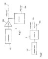
- Fig.1 is a preferred embodiment of the control device for watercrafts, according to the present invention, particularly for watecrafts of the type comprising at least: a control station 1 provided with at least a control lever 2, a motor 3, an actuator 4 associated to said motor.
- the control lever 2 is provided with a sensing means, for detecting a main command signal that can be set by means of the control lever 2.
- the lever is operated by a user, tipically for controlling the motor or motors of the watercraft.
- Inputs set by the user by means of a single lever regard the gear and the number of revolutions of the motor for example figs. 7, 8 and 9 show three positions of a single control lever 2, particularly the lever 2 in the position of fig.7 corresponds to the minimum number of revolutions of the motor and to the "neutral" gear, that is the motor propeller does not rotate.
- the position of the lever 2 means that the forward gear is set, and by progressively moving the lever from the neutral position of fig.7 to the maximum travel of the lever there is the progressive and corresponding increase in the number of revolutions of the motor.
- a progressive increase in the number of revolutions of the motor occurs corresponding to the progressive displacement of the lever 2, while corresponding to the reverse gear.
- a first control lever for controlling the number of motor revolutions and a separated control member for setting the gear, such as a second commutating lever, a commutator or the like.
- the commutating lever provides a plurality of predetermined angular positions, each one corresponding to the command for setting a gear among the available ones, tipically but not exclusively among three gear conditions and i.e. forward gear, reverse gear and neutral, or disengagement.
- a device of this type there are provided two levers or one lever and a commutator, and the user operates the first control lever in order to set the number of revolutions of the motor, transmitting an analog signal thereto, while he operates the commutator or the second lever in order to set the desired gear, transmitting to the motor, that is the electromechanical actuator of the reversing gear a digital signal setting the corresponding gear or operably related to the position of the second commutating lever.
- the first control lever 2, 2' by means of sensors or transducers of the mechanical/analog type generates the analog command signal setting the number of revolutions of the motor.
- the control member setting the gear i.e. the commutating lever 2'' or 2''' generates the digital command signal setting the gear by means of electromechanical transducers intended for generating a digital signal.
- the sensing means detecting and/or generating a command signal corresponding to or operably related to the position and/or the displacement of said control lever 2 is an electromechanical sensing means such as a potentiometer associated to the control lever or the like, or as an alternative it is an electric/electronic and/or digital sensing means such as a magnetic sensor associated to the control lever or the like.
- the device comprises at least a control electronics 5 intended to receive as input at least the command signal, anyhow it is trasmitted to electronics 5, and it comprises at least two different lines for transmitting command signals, a first analog transmission line 105 and a second digital transmission line 205, that are shown in figs. 1 , 2 and 3 .
- the control electronics 5 divides the main command signal into two different command signals, a first analog command signal and a second digital command signal, which are sent to an actuating means 4 by means of the analog transmission line 105 and by means of the digital transmission line 205.
- the command signal received as input by the electronics 5 is a command signal containing information regarding the position or displacement and the displacement direction with respect to a specific reference position of the lever 2.
- a control electronics is not provided, but the command signal is directly sent from analog and/or digital sensors to the actuating means of the motor or the like with two separated transmission lines, an analog transmission line and a digital transmission line, each one connected to respective sensors or transducers, analog and digital ones.
- the analog signal is a command signal containing at least information about the position or the progressive displacement of the corresponding control lever, for example as a potential difference.
- the digital command signal contains at least information about the desired gear, and said information can be operably related to or corresponds to the displacement direction of the lever with respect to a specific reference position, but it can contain also information about error detections or the like.
- an information transmission lower than 10 bit and preferably there is an information transmission with a band substantially equal to 4 bit, and equal to information about the set gear.
- a first embodiment comprising a sensor/transducer 102 of the analog type, intended to be dinamically connected to the control lever 2 and to detect displacements and/or the progressive position of the lever and/or the displacement direction.
- An example of the analog sensor 102 could be for example a potentiometer that is dinamically connected to the control lever and provided with a rotating driving shaft that is rotatably operated by the angular movement of the lever by means of a direct transmission or by means of a kinematic transmission chain.
- the command signal is already in the form of an analog command signal and it passes in a buffer 202, from which buffer it is sent both to the control electronics 5, converting it in a corresponding digital signal and sends it by means of the digital line or digital output of the electronics, and to the analog line 105 directly transmitting it to the actuating means associated to the motor or to the motor.
- a digital sensor 102' intended to be connected to the control lever 2 and to detect displacements and/or the progressive position of the lever and/or the displacement direction.
- An example of a digital sensor 102' could be for example a magnetic sensor with a digital output, associated to the lever base.
- the command signal is in the form of a digital command signal and it is sent both to the control electronics 5, dividing it into a corresponding digital signal and a corresponding analog signal and sends it by the digital line 105 or digital output of electronics and by means of the analog line 205 or analog output of the electronics.
- the digital transmission line is a BUS one, preferably a BUS Can.
- Fig.4 shows an embodiment where there are two control levers a first lever 2, and a second lever 2' provided in two different control stations, a first station 101 and a second station 101'. These stations can be placed at different locations in the watercraft.
- the command signal of the lever 2' is sent to the control electronics 5', which control electronics changes it into an analog signal or a digital signal, preferably a digital signal and sends it to the control electronics of the first lever 5.
- the latter divides said signal into an analog signal and a digital signal and sends it to the motor and/or actuating means.
- the system comprises a first lever 2, so called MASTER lever, which first lever 2 is connected to two transmission lines, a digital one and an analog one, which two lines are connected to an actuating means or directly to one or more motors.
- SLAVE lever that can be selected by the user as the lever by means of which the user inputs the command for the motor or motors.
- the SLAVE lever 2' communicates with the MASTER lever 2 preferably only through a communication line 205' of the digital type, that is a BUS, advantageously a BUS Can, by means of which communication line 205' it sends the command signal to the control electronics 5 of the MASTER lever 2 and which control electronics 5 provides to divide the signal into a digital part, for example regarding the set gear and into an analog part, for example regarding the position or progressive displacement of the SLAVE lever 2'.
- a communication line 205' of the digital type that is a BUS, advantageously a BUS Can
- the MASTER lever 2 if a SLAVE lever 2' is provided by means of which the user inputs commands, is provided with a servomechanism for operating the MASTER lever 2 such that it corresponds to the command set by the user on the SLAVE lever 2'.
- the embodiment of fig 5 is particularly advantageous in the case of watercrafts provided with outboard motors, while the embodiment of fig.6 in the case of watercrafts provided with inboard motors.
- Fig.5 shows an embodiment of the present invention in the case of two different control stations MASTER 101 and SLAVE 101' each one provided with two control levers 2, 2',2'' and 2'''.
- FIG 5 there are provided four actuators 4 and a first transmission line 205' connecting the station 101' to the station 101, and it is composed of a digital transmission line, that is a BUS, and specifically a BUS Can.
- each lever 2, 2',2'' and 2''' to be intended for controlling one, two, three or more actuators, like what described above.
- the first transmission line 5' is provided integrally with the transmission line 5 connecting the MASTER station 101 to actuators, for example by manufacturing them as a single digital transmission line such as a BUS Can or the like and not as two separated transmission lines.
- control stations there can be provided more than two control stations, for example there can be provided three, four or more control stations wherein at least one is intended for being a MASTER control station like what described above.
- the device according to the present invention can be modified in that the command signal is divided into a digital part and into a analog part, but wherein the digital part of the command signal transmitted on the digital line 205 contains also a command signal exactly alike the one transmitted along the analog line, such that the signal part of the analog signal can be also checked, otherwise it would be virtually free from checking.
- the fact of checking the correct transmission of the analog signal can be made at the actuator, by the actuator or by a dedicated checking electronics verifying the correct transmission of the analog signal by comparing it with the digital one.
- the check is not carried out continuously but it is carried out at preferred intervals, that is the correspondance between the digital signal corresponding to the analog signal and the analog signal is checked only at predetermined intervals for example 5 seconds, 10 seconds, 60 seconds, or only when the device is operated.
- a furhter advantageous characteristic provides that in combination with the device of the present invention there is provided an actuating means 10 such as shown in figures 10 and 11 .
- the assembling of a normal cable 15 according to prior art is made on the actuator 10 according to the present invention by securing the sheath 17 of the cable 15 onto a stationary fastening terminal, while the head 13 of the cable is integral with a mobile member, in this case it is a stem 11 of a linear actuator, by means of a coupling means 12.
- the location where the sheath 17 is secured defines the type of cable that can be used, since the distance between the cable head 13 and the sheath 17 is characteristic for different types of cables and particularly for identical types of cables made by different manufacturers.
- the actuator 10 provides a terminal for fastening the sheath 17 of the cable that is movable with respect to means 12 coupling the cable head. Particularly this is achieved by means of a slide 14 sliding onto a guide 18 that is integral with the body of the actuator 10 in the direction removing and approaching it to coupling means 12 on the stem 11.
- the slide 14 bearing the terminal fastening the sheath 17 can be moved in a direction parallel to the axis of the stem 11, i.e. to its displacement direction, by means of a corresponding arrangement of the guide.
- both the stationary piece and the mobile piece are part of the actuator according to the present invention.
- the terminal fastening the sheath 17 is provided on a slide, it is possible to change the distance of the location where the sheath is fastened or secured and so to adapt the actuator for any type of selected cable, apart from the distance between the cable head and the location where the sheath is fastened.
- the slide is stopped in place by tightening two screws or by means of other securing or stopping members.
- Cables are characterized not only as regards the distance between sheath and head as said above but also as regards the type of terminal fastening the sheath, that usually it is a cylinder 114 whose size changes depending on the model.
- the slide of the terminal fastening the sheath according to the present invention has such a seat to house different types of cylinders fastening the sheath, such that the actuator of the present invention is still more versatile.
- the system for positioning the stem is made by a linear position sensor, such as a potentiometer or the like, detecting the position of the stem as an electric signal, which position is then used for an absolute position feedback for the device according to the present invention, such that the correspondence between the command of the user and the command sent to the motor means or to the member of the motor means can be checked at predetermined intervals.
- a linear position sensor such as a potentiometer or the like
- the actuator is shown in a section view along a diametral plane of the stem 11 perpendicular to the bottom side of the case of the actuator.
- the hollow stem 11 at one end has a female screw 22 not rotatably fastened thereto.
- a threaded shaft 21 engages the female screw 22 which is rotatably supported about its axis and with respect to the female screw 22 and which is rotatably driven by a motorized transmission generally denoted by 20.
- the axially slidable stem 11 and particularly the female screw 22 have a control member 23 of a position sensor or a stroke measuring device of the stem 11 denoted by 24 and it is provided parallel to the stem and in the displacement direction thereof.
- the stroke measuring device or position sensor are of the electric type such as a linear potentiometer or the like.
- the member controlling it is a tracer point in the form of a contact ball that is elastically urged against the sensitive band of the potentiometer.
- other type of similar solutions using other known types of sensors 24 are possible.
Landscapes
- Engineering & Computer Science (AREA)
- Chemical & Material Sciences (AREA)
- Mechanical Engineering (AREA)
- Combustion & Propulsion (AREA)
- Computer Hardware Design (AREA)
- Microelectronics & Electronic Packaging (AREA)
- Physics & Mathematics (AREA)
- Automation & Control Theory (AREA)
- General Physics & Mathematics (AREA)
- General Engineering & Computer Science (AREA)
- Ocean & Marine Engineering (AREA)
- Mechanical Control Devices (AREA)
- Centrifugal Separators (AREA)
- Physical Deposition Of Substances That Are Components Of Semiconductor Devices (AREA)
- Control Of Motors That Do Not Use Commutators (AREA)
- Control Of Electric Motors In General (AREA)
Applications Claiming Priority (1)
| Application Number | Priority Date | Filing Date | Title |
|---|---|---|---|
| IT000072A ITGE20070072A1 (it) | 2007-07-27 | 2007-07-27 | Dispositivo di comando per imbarcazioni |
Publications (1)
| Publication Number | Publication Date |
|---|---|
| EP2019036A2 true EP2019036A2 (fr) | 2009-01-28 |
Family
ID=40042943
Family Applications (1)
| Application Number | Title | Priority Date | Filing Date |
|---|---|---|---|
| EP08160278A Withdrawn EP2019036A2 (fr) | 2007-07-27 | 2008-07-11 | Dispositif de commande de bateau |
Country Status (4)
| Country | Link |
|---|---|
| US (1) | US8165736B2 (fr) |
| EP (1) | EP2019036A2 (fr) |
| CA (1) | CA2637580A1 (fr) |
| IT (1) | ITGE20070072A1 (fr) |
Cited By (3)
| Publication number | Priority date | Publication date | Assignee | Title |
|---|---|---|---|---|
| FR2998618A1 (fr) * | 2012-11-27 | 2014-05-30 | Motorisations Aeronautiques | Dispositif de positionnement d'un organe de commande d'une pompe d'injection |
| EP3156320A1 (fr) | 2015-10-13 | 2017-04-19 | Ultraflex Spa | Système de commande de bateau |
| IT201900002659A1 (it) | 2019-02-25 | 2020-08-25 | Ultraflex Spa | Sistema di comando per imbarcazioni |
Families Citing this family (6)
| Publication number | Priority date | Publication date | Assignee | Title |
|---|---|---|---|---|
| IT1391422B1 (it) * | 2008-08-01 | 2011-12-23 | Ultraflex Spa | Comando monoleva per il controllo combinato della alimentazione di motori marini e dell'invertitore |
| IT1395074B1 (it) * | 2009-08-06 | 2012-09-05 | Ultraflex Spa | Comando monoleva per il controllo combinato della condizione di alimentazione di uno o piu' motori e di un meccanismo invertitore di cambio marcia |
| US8604772B2 (en) | 2010-03-31 | 2013-12-10 | General Electric Company | MEMS-based resonant tunneling devices and arrays of such devices for electric field sensing |
| US9043058B1 (en) * | 2013-03-14 | 2015-05-26 | Brunswick Corporation | Systems and methods for facilitating shift changes in marine propulsion devices |
| CN109612514B (zh) * | 2018-12-28 | 2021-09-07 | 广东逸动科技有限公司 | 一种调速装置控制系统的调速装置校准方法 |
| JP2022090257A (ja) * | 2020-12-07 | 2022-06-17 | ヤマハ発動機株式会社 | 操船システムおよび船舶 |
Family Cites Families (11)
| Publication number | Priority date | Publication date | Assignee | Title |
|---|---|---|---|---|
| US4632232A (en) * | 1984-07-02 | 1986-12-30 | Outboard Marine Corporation | Single lever remote control-throttle dwell and friction mechanism |
| US4645462A (en) * | 1985-05-17 | 1987-02-24 | Fulton Hubert S | Trolling motor guide |
| US4925416A (en) * | 1987-06-12 | 1990-05-15 | Sanshin Kogyo Kabushiki Kaisha | Clutch for marine propulsion |
| US5094122A (en) * | 1991-01-23 | 1992-03-10 | Sanshin Kogyo Kabushiki Kaisha | Remote control system |
| IT1263481B (it) * | 1993-12-16 | 1996-08-05 | Ultraflex Srl | Dispositivo elettromeccanico di comando a distanza. |
| JPH10280983A (ja) * | 1997-04-02 | 1998-10-20 | Sanshin Ind Co Ltd | 4サイクルエンジン付船外機の制御機構 |
| EP1246754B1 (fr) * | 2000-01-14 | 2005-10-26 | Siemens Aktiengesellschaft | Systeme de propulsion pour bateau muni d'une regulation adaptee a la dynamique |
| JP4509406B2 (ja) * | 2000-03-17 | 2010-07-21 | ヤマハ発動機株式会社 | 水ジェット推進艇のエンジン出力制御装置 |
| EP1331385A1 (fr) * | 2000-10-30 | 2003-07-30 | Yamaha Hatsudoki Kabushiki Kaisha | Dispositif de commande de navigation |
| JP4462589B2 (ja) * | 2001-02-13 | 2010-05-12 | 本田技研工業株式会社 | 船外機 |
| CA2516887C (fr) * | 2004-08-25 | 2008-03-18 | Honda Motor Co., Ltd. | Systeme de commande a distance pour hors-bord |
-
2007
- 2007-07-27 IT IT000072A patent/ITGE20070072A1/it unknown
-
2008
- 2008-07-11 EP EP08160278A patent/EP2019036A2/fr not_active Withdrawn
- 2008-07-15 CA CA002637580A patent/CA2637580A1/fr not_active Abandoned
- 2008-07-16 US US12/173,816 patent/US8165736B2/en not_active Expired - Fee Related
Cited By (5)
| Publication number | Priority date | Publication date | Assignee | Title |
|---|---|---|---|---|
| FR2998618A1 (fr) * | 2012-11-27 | 2014-05-30 | Motorisations Aeronautiques | Dispositif de positionnement d'un organe de commande d'une pompe d'injection |
| WO2014083272A1 (fr) * | 2012-11-27 | 2014-06-05 | Societe De Motorisation Aeronautiques | Dispositif de positionnement d'un organe de commande d'une pompe d'injection |
| EP3156320A1 (fr) | 2015-10-13 | 2017-04-19 | Ultraflex Spa | Système de commande de bateau |
| IT201900002659A1 (it) | 2019-02-25 | 2020-08-25 | Ultraflex Spa | Sistema di comando per imbarcazioni |
| EP3699714A2 (fr) | 2019-02-25 | 2020-08-26 | Ultraflex Spa | Système de commande pour bateaux |
Also Published As
| Publication number | Publication date |
|---|---|
| US8165736B2 (en) | 2012-04-24 |
| US20090030567A1 (en) | 2009-01-29 |
| CA2637580A1 (fr) | 2009-01-27 |
| ITGE20070072A1 (it) | 2009-01-28 |
Similar Documents
| Publication | Publication Date | Title |
|---|---|---|
| EP2019036A2 (fr) | Dispositif de commande de bateau | |
| EP1598267B1 (fr) | Systéme et méthode pour gouverner un bateau | |
| EP1876339B1 (fr) | Organe de détection de la position angulaire d'une poignée d'accélérateur d'une motocyclette | |
| US5492493A (en) | Remote control device for marine propulsion unit | |
| JP5105464B2 (ja) | 複数ワイヤ操舵ヘルムシステム | |
| US8583294B2 (en) | Actuation control system | |
| US11479364B2 (en) | Aircraft torque control device | |
| CN102530221A (zh) | 一种船外机自动转向机构 | |
| US8128443B2 (en) | Single lever control for combined control of the throttle in a marine engine and of a reversing gear | |
| US8210206B2 (en) | Dual redundant servovalve | |
| CN109249984B (zh) | 用于线控转向系统的转向装置 | |
| CN113365913B (zh) | 用于飞行器的控制棒的力施加设备 | |
| US8419488B2 (en) | Steering apparatus for outboard motor | |
| KR102374805B1 (ko) | 멀티 턴 회전각 인식이 가능한 전기식 구동장치 | |
| US5094122A (en) | Remote control system | |
| KR101890313B1 (ko) | 오작동 및 고장을 방지하는 센서 신호 입력형 항공기용 전기식 구동장치 | |
| EP1865590B1 (fr) | Agencement d'actionneur | |
| US8430446B2 (en) | Spindle drive | |
| EP2604508A1 (fr) | Système de direction pour un moteur hors-bord | |
| US8354838B2 (en) | Arrangement for contactlessly measuring a position using a magnetoresistive sensor, and method for operating the arrangement | |
| US20050148247A1 (en) | Electromechanical control device particularly for boats | |
| KR101959235B1 (ko) | 이동가능한 부품에 장착된 포인터의 위치를 감지하기 위한 회로 구조물을 갖는 비접촉 위치 센서 | |
| KR200294520Y1 (ko) | 선박용 조타장치 | |
| CN109397298B (zh) | 一种并联机器人初始位置标定方法 | |
| US20160243709A1 (en) | Robotic gripper |
Legal Events
| Date | Code | Title | Description |
|---|---|---|---|
| PUAI | Public reference made under article 153(3) epc to a published international application that has entered the european phase |
Free format text: ORIGINAL CODE: 0009012 |
|
| AK | Designated contracting states |
Kind code of ref document: A2 Designated state(s): AT BE BG CH CY CZ DE DK EE ES FI FR GB GR HR HU IE IS IT LI LT LU LV MC MT NL NO PL PT RO SE SI SK TR |
|
| AX | Request for extension of the european patent |
Extension state: AL BA MK RS |
|
| STAA | Information on the status of an ep patent application or granted ep patent |
Free format text: STATUS: THE APPLICATION IS DEEMED TO BE WITHDRAWN |
|
| 18D | Application deemed to be withdrawn |
Effective date: 20140201 |