EP2018719B1 - Half-duplex communication in a frequency division duplex system - Google Patents
Half-duplex communication in a frequency division duplex system Download PDFInfo
- Publication number
- EP2018719B1 EP2018719B1 EP07783953.8A EP07783953A EP2018719B1 EP 2018719 B1 EP2018719 B1 EP 2018719B1 EP 07783953 A EP07783953 A EP 07783953A EP 2018719 B1 EP2018719 B1 EP 2018719B1
- Authority
- EP
- European Patent Office
- Prior art keywords
- duplex
- terminal
- forward link
- frames
- interlace
- Prior art date
- Legal status (The legal status is an assumption and is not a legal conclusion. Google has not performed a legal analysis and makes no representation as to the accuracy of the status listed.)
- Active
Links
Images


Classifications
-
- H—ELECTRICITY
- H04—ELECTRIC COMMUNICATION TECHNIQUE
- H04L—TRANSMISSION OF DIGITAL INFORMATION, e.g. TELEGRAPHIC COMMUNICATION
- H04L5/00—Arrangements affording multiple use of the transmission path
- H04L5/14—Two-way operation using the same type of signal, i.e. duplex
- H04L5/16—Half-duplex systems; Simplex/duplex switching; Transmission of break signals non-automatically inverting the direction of transmission
-
- H—ELECTRICITY
- H04—ELECTRIC COMMUNICATION TECHNIQUE
- H04B—TRANSMISSION
- H04B7/00—Radio transmission systems, i.e. using radiation field
- H04B7/24—Radio transmission systems, i.e. using radiation field for communication between two or more posts
- H04B7/26—Radio transmission systems, i.e. using radiation field for communication between two or more posts at least one of which is mobile
- H04B7/2643—Radio transmission systems, i.e. using radiation field for communication between two or more posts at least one of which is mobile using time-division multiple access [TDMA]
- H04B7/2656—Radio transmission systems, i.e. using radiation field for communication between two or more posts at least one of which is mobile using time-division multiple access [TDMA] for structure of frame, burst
-
- H—ELECTRICITY
- H04—ELECTRIC COMMUNICATION TECHNIQUE
- H04B—TRANSMISSION
- H04B7/00—Radio transmission systems, i.e. using radiation field
- H04B7/24—Radio transmission systems, i.e. using radiation field for communication between two or more posts
- H04B7/26—Radio transmission systems, i.e. using radiation field for communication between two or more posts at least one of which is mobile
- H04B7/2628—Radio transmission systems, i.e. using radiation field for communication between two or more posts at least one of which is mobile using code-division multiple access [CDMA] or spread spectrum multiple access [SSMA]
-
- H—ELECTRICITY
- H04—ELECTRIC COMMUNICATION TECHNIQUE
- H04J—MULTIPLEX COMMUNICATION
- H04J1/00—Frequency-division multiplex systems
-
- H—ELECTRICITY
- H04—ELECTRIC COMMUNICATION TECHNIQUE
- H04L—TRANSMISSION OF DIGITAL INFORMATION, e.g. TELEGRAPHIC COMMUNICATION
- H04L1/00—Arrangements for detecting or preventing errors in the information received
- H04L1/12—Arrangements for detecting or preventing errors in the information received by using return channel
- H04L1/16—Arrangements for detecting or preventing errors in the information received by using return channel in which the return channel carries supervisory signals, e.g. repetition request signals
- H04L1/18—Automatic repetition systems, e.g. Van Duuren systems
-
- H—ELECTRICITY
- H04—ELECTRIC COMMUNICATION TECHNIQUE
- H04L—TRANSMISSION OF DIGITAL INFORMATION, e.g. TELEGRAPHIC COMMUNICATION
- H04L27/00—Modulated-carrier systems
- H04L27/26—Systems using multi-frequency codes
Landscapes
- Engineering & Computer Science (AREA)
- Signal Processing (AREA)
- Computer Networks & Wireless Communication (AREA)
- Mobile Radio Communication Systems (AREA)
- Bidirectional Digital Transmission (AREA)
Description
- The present disclosure relates generally to wireless communications, and more specifically to techniques for transmitting data in a wireless communication system.
- Wireless communication systems are widely deployed to provide various communication services; for instance, voice, video, packet data, broadcast, and messaging services may be provided via such wireless communication systems. These systems may be multiple-access systems that are capable of supporting communication for multiple terminals by sharing available system resources. Examples of such multiple-access systems include Code Division Multiple Access (CDMA) systems, Time Division Multiple Access (TDMA) systems, Frequency Division Multiple Access (FDMA) systems, and Orthogonal Frequency Division Multiple Access (OFDMA) systems.
- Traditionally, a wireless communication system, also referred to as an access network (AN), utilizes either frequency division duplexing (FDD) or time division duplexing (TDD) for data transmission between base stations and terminals (e.g., access terminals or ATs) on the forward and reverse links. The forward link (or "downlink") refers to the communication link from the base stations to one or more terminals, while the reverse link (or "uplink") refers to the communication link from a terminal to one or more base stations. In a wireless communication system utilizing FDD, separate frequency channels are used for the forward and reverse links. A terminal may simultaneously receive data on a forward link (FL) frequency channel and transmit data on a reverse link (RL) frequency channel. In contrast, in a wireless communication system utilizing TDD, a single frequency channel is used for both the forward and reverse links. The transmission timeline in such a system is partitioned into time intervals, with certain time intervals being used for FL transmission and other time intervals being used for RL transmission. Based on this partitioning, a terminal may transmit data on the frequency channel in time intervals reserved for RL transmission and may receive data in time intervals reserved for FL transmission.
- A terminal designed for operation in an FDD system is able to receive and transmit at the same time by using a duplexer, which assigns FL communications and RL communications different frequency bands to allow simultaneous FL and RL communication. However, a terminal may be designed for operation in a TDD system and may lack a duplexer to allow the terminal to receive and transmit at the same time. Thus, the terminal would not be able to operate in a typical FDD system that supports simultaneous transmission and reception on two frequency channels. Further, duplexers can be costly to implement and as a result may not be desirable for some terminals in an access network. In addition, it has traditionally been difficult to build a duplexer for a terminal that operates in a high-bandwidth access network that cleanly separates two frequency bands due to the high bandwidth of the network. The document
US2002/0118666 A1 discloses a half-duplex FDD communications system comprising temporally non-overlapping uplink and downlink events. - The invention is defined by the appended claims.
- The following presents a simplified summary of the disclosed embodiments in order to provide a basic understanding of such embodiments. This summary is not an extensive overview of all contemplated embodiments, and is intended to neither identify key or critical elements nor delineate the scope of such embodiments. Its sole purpose is to present some concepts of the disclosed embodiments in a simplified form as a prelude to the more detailed description that is presented later.
- The described embodiments mitigate the above-mentioned problems by providing half-duplex communication in an FDD system. More particularly, one or more embodiments separate communications in an FDD system into half-duplex interlaces, wherein a terminal may receive at one time period and transmit at another time period in a similar manner to a TDD system. By separating an FDD system into half-duplex interlaces, a terminal that lacks a duplexer (e.g., a terminal designed for operation in TDD systems) may be allowed to function in an FDD system.
- According to an aspect, a method that facilitates half-duplex communication in a wireless communication system is described herein. The method may comprise determining a half-duplex interlace to use for communication from among a plurality of half-duplex interlaces, each half-duplex interlace in the plurality of half-duplex interlaces including temporally non-overlapping frames for a forward link and a reverse link. Further, the method may include communicating using frames of the half-duplex interlace determined for use.
- Another aspect relates to a wireless communications apparatus that may include a memory that stores data relating to a plurality of half-duplex interlaces, wherein each of the plurality of half-duplex interlaces includes temporally non-overlapping frames for a forward link and a reverse link. Further, the wireless communications apparatus may include a processor configured to determine a half-duplex interlace to use for communication from among the plurality of half-duplex interlaces.
- Yet another aspect relates to an apparatus that facilitates half-duplex communication in a wireless communication system. The apparatus may comprise means for determining a half-duplex interlace to use for communication from among a plurality of half-duplex interlaces, each half-duplex interlace in the plurality of half-duplex interlaces including temporally non-overlapping frames for a forward link and a reverse link. Additionally, the apparatus may include means for communicating using frames of the half-duplex interlace determined for use.
- Still another aspect relates to a computer-readable medium having stored thereon computer-executable instructions for half-duplex communication in a wireless communication system. The instructions may comprise allocating frames of a forward link and a reverse link among a plurality of half-duplex interlaces such that each of the plurality of half-duplex interlaces has temporally non-overlapping frames. Additionally, the instructions may also include associating an access terminal with a half-duplex interlace from the plurality of half-duplex interlaces. Further, the instructions may include communicating with the access terminal using frames allocated for the associated half-duplex interlace.
- In accordance with another aspect, a processor is described herein that may execute computer-executable instructions for half-duplex communication in a wireless communication system. These instructions may include communicating with a first terminal using half-duplex in a frequency division duplex (FDD) communication system. These instructions may additionally include communicating with a second terminal using full-duplex.
- In accordance with yet another aspect, a method that facilitates half-duplex communication in a wireless communication system is described herein. The method may comprise associating with a half-duplex interlace chosen from a plurality of half-duplex interlaces for communication with an access network, each half-duplex interlace including temporally non-overlapping frames for a forward link and a reverse link. In addition, the method may include communicating with the access network using frames of the associated half-duplex interlace.
- Another aspect relates to a wireless communications apparatus, which may comprise a memory that stores data relating to an associated half-duplex interlace, the selected half-duplex interlace includes temporally non-overlapping frames for a forward link and a reverse link. Further, the wireless communications apparatus may include a processor configured to communicate with an access network using frames of the associated half-duplex interlace.
- Yet another aspect relates to an apparatus that facilitates half-duplex communication in a wireless communication system. The apparatus may include means for associating with a half-duplex interlace chosen from a plurality of half-duplex interlaces for communication with an access network, each half-duplex interlace including temporally non-overlapping frames for a forward link and a reverse link. Additionally, the apparatus may include means for communicating with the access network using frames of the associated half-duplex interlace.
- In accordance with another aspect, a computer-readable medium having stored thereon computer-executable instructions for half-duplex communication in a wireless communication system. The instructions may comprise associating with a half-duplex interlace selected from a plurality of half-duplex interlaces, each of the plurality of half-duplex interlaces having allocated frames of a forward link and a reverse link such that each of the plurality of half-duplex interlaces has temporally non-overlapping frames. Further, the instructions may include communicating with an access network using the allocated frames for the associated half-duplex interlace.
- Still another aspect relates to a processor that executes computer-executable instructions for half-duplex communication in a wireless communication system. The instructions may include receiving an assignment of resources in frames of a half-duplex interlace selected from a plurality of half-duplex interlaces. In addition, the instructions may include communicating with an access network using the assigned resources.
- To the accomplishment of the foregoing and related ends, one or more embodiments comprise the features hereinafter fully described and particularly pointed out in the claims. The following description and the annexed drawings set forth in detail certain illustrative aspects of the disclosed embodiments. These aspects are indicative, however, of but a few of the various ways in which the principles of various embodiments may be employed. Further, the disclosed embodiments are intended to include all such aspects and their equivalents.
-
-
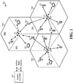
FIG. 1 illustrates a wireless multiple-access communication system in accordance with various aspects set forth herein. -
FIG. 2 is a block diagram of a system that provides half-duplex communication in accordance with various aspects. -
FIG. 3 illustrates an example FDD superframe structure in accordance with various aspects. -
FIG. 4 illustrates an example TDD 1:1 superframe structure in accordance with various aspects. -
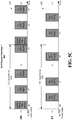
FIGS. 5A-5C illustrates an example FDD half-duplex superframe structure in accordance with various aspects. -
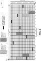
FIG. 6 illustrates an example transmission scheme for CDMA control segments in accordance with various aspects. -
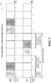
FIG. 7 illustrates an example FDD half-duplex forward link retransmission structure in accordance with various aspects. -
FIG. 8 illustrates an example FDD half-duplex reverse link retransmission structure in accordance with various aspects. -
FIG. 9 is a flow diagram of a methodology for half-duplex communication in an FDD system. -
FIG. 10 is a flow diagram of a methodology for half-duplex communication in an FDD system. -
FIG. 11 is a flow diagram of a methodology for communicating with half-duplex and full-duplex terminals in an FDD system. -
FIG. 12 is a block diagram illustrating an example wireless communication system in which one or more embodiments described herein may function. -
FIG. 13 is a block diagram of a system that coordinates FDD half-duplex communication in accordance with various aspects. -
FIG. 14 is a block diagram of a system that coordinates FDD half-duplex communication in accordance with various aspects. -
FIG. 15 is a block diagram of a system that facilitates half-duplex communication in an FDD system. -
FIG. 16 is a block diagram of a system that facilitates half-duplex communication in an FDD system. -
FIG. 17 is a block diagram of a system that facilitates communication with half-duplex and full-duplex terminals in an FDD system. - Various embodiments are now described with reference to the drawings, wherein like reference numerals are used to refer to like elements throughout. In the following description, for purposes of explanation, numerous specific details are set forth in order to provide a thorough understanding of one or more aspects. It may be evident, however, that such embodiment(s) may be practiced without these specific details. In other instances, well-known structures and devices are shown in block diagram form in order to facilitate describing one or more embodiments.
- As used in this application, the terms "component," "module," "system," and the like are intended to refer to a computer-related entity, either hardware, firmware, a combination of hardware and software, software, or software in execution. For example, a component may be, but is not limited to being, a process running on a processor, a processor, an object, an executable, a thread of execution, a program, and/or a computer. By way of illustration, both an application running on a computing device and the computing device can be a component. One or more components can reside within a process and/or thread of execution and a component may be localized on one computer and/or distributed between two or more computers. In addition, these components can execute from various computer readable media having various data structures stored thereon. The components may communicate by way of local and/or remote processes such as in accordance with a signal having one or more data packets (e.g., data from one component interacting with another component in a local system, distributed system, and/or across a network such as the Internet with other systems by way of the signal).
- Furthermore, various embodiments are described herein in connection with a wireless terminal and/or a base station. A wireless terminal may refer to a device providing voice and/or data connectivity to a user. A wireless terminal may be connected to a computing device such as a laptop computer or desktop computer, or it may be a self contained device such as a personal digital assistant (PDA). A wireless terminal can also be called a system, a subscriber unit, a subscriber station, mobile station, mobile, remote station, access point, remote terminal, access terminal, user terminal, user agent, user device, or user equipment. A wireless terminal may be a subscriber station, wireless device, cellular telephone, PCS telephone, cordless telephone, a Session Initiation Protocol (SIP) phone, a wireless local loop (WLL) station, a personal digital assistant (PDA), a handheld device having wireless connection capability, or other processing device connected to a wireless modem. A base station (e.g., access point) may refer to a device in an access network that communicates over the air-interface, through one or more sectors, with wireless terminals. The base station may act as a router between the wireless terminal and the rest of the access network, which may include an Internet Protocol (IP) network, by converting received air-interface frames to IP packets. The base station also coordinates management of attributes for the air interface.
- Moreover, various aspects or features described herein may be implemented as a method, apparatus, or article of manufacture using standard programming and/or engineering techniques. The term "article of manufacture" as used herein is intended to encompass a computer program accessible from any computer-readable device, carrier, or media. For example, computer readable media can include but are not limited to magnetic storage devices (e.g., hard disk, floppy disk, magnetic strips...), optical disks (e.g., compact disk (CD), digital versatile disk (DVD)...), smart cards, and flash memory devices (e.g., card, stick, key drive...).
- Various embodiments will be presented in terms of systems that may include a number of devices, components, modules, and the like. It is to be understood and appreciated that the various systems may include additional devices, components, modules, etc. and/or may not include all of the devices, components, modules etc. discussed in connection with the figures. A combination of these approaches may also be used.
- Referring now to the drawings,
Fig. 1 is an illustration of a wireless multiple-access communication system 100 in accordance with various aspects. In one example, the wireless multiple-access communication system 100 includesmultiple base stations 110 andmultiple terminals 120. Further, one ormore base stations 110 can communicate with one ormore terminals 120. By way of non-limiting example, abase station 110 may be an access point, a Node B, and/or another appropriate network entity. Eachbase station 110 provides communication coverage for a particular geographic area 102. As used herein and generally in the art, the term "cell" can refer to abase station 110 and/or its coverage area 102 depending on the context in which the term is used. To improve system capacity, the coverage area 102 corresponding to abase station 110 may be partitioned into multiple smaller areas (e.g.,areas smaller areas base station 110 for the cell 102. - In another example, the
system 100 can utilize a centralized architecture by employing asystem controller 130 that can be coupled to one ormore base stations 110 and provide coordination and control for thebase stations 110. In accordance with alternative aspects,system controller 130 may be a single network entity or a collection of network entities. Additionally, thesystem 100 may utilize a distributed architecture to allow thebase stations 110 to communicate with each other as needed. - In accordance with one aspect,
terminals 120 may be dispersed throughout thesystem 100. Each terminal 120 may be stationary or mobile. By way of non-limiting example, a terminal 120 may be an access terminal (AT), a mobile station, user equipment, a subscriber station, and/or another appropriate network entity. A terminal may be a wireless device, a cellular phone, a personal digital assistant (PDA), a wireless modem, a handheld device, and so on. - In accordance with another aspect,
system 100 may utilize FDD and support simultaneous transmission on a forward link (FL) and a reverse link (RL) via two separate frequency channels. In addition,system 100 may support full-duplex communication forterminals 120 that are capable of full-duplex operation ("full-duplex terminals"). As used herein and generally in the art, full-duplex refers to a mode in which a station (e.g., abase station 110 or a terminal 120) may simultaneously transmit and receive at the same time. In one example, a station capable of full-duplex operation may be equipped with a single antenna for both transmission and reception. Thus, the station can have a duplexer, which can route a received signal from the antenna to a receiver for data reception and route a modulated signal from a transmitter to the antenna for data transmission. - Additionally,
system 100 may also support half-duplex communication forterminals 120 not capable of full-duplex operation ("half-duplex terminals"). As used herein and generally in the art, half-duplex refers to a mode in which a station may either transmit or receive at any given moment but may not simultaneously transmit and receive. In one example, a station capable only of half-duplex operation may be equipped with a single antenna for both transmission and reception. Thus, the station may have a switch that can connect the antenna to a receiver during periods of data reception and connect a transmitter to the antenna during periods of data transmission. - In another example,
system 100 may utilize one or more multiple-access schemes, such as CDMA, TDMA, FDMA, OFDMA, Single-Carrier FDMA (SC-FDMA), and/or other suitable multiple-access schemes. OFDMA utilizes Orthogonal Frequency Division Multiplexing (OFDM), and SC-FDMA utilizes Single-Carrier Frequency Division Multiplexing (SC-FDM). OFDM and SC-FDM can partition the system bandwidth into multiple orthogonal subcarriers (e.g., tones, bins, ...), each of which may be modulated with data. Typically, modulation symbols are sent in the frequency domain with OFDM and in the time domain with SC-FDM. Additionally,system 100 may utilize a combination of multiple-access schemes, such as OFDMA and CDMA. Additionally,system 100 may utilize various framing structures to indicate the manner in which data and signaling are sent on the forward and reverse links. For clarity, non-limiting examples of framing structures thatsystem 100 may utilize are described in more detail herein. - Additionally,
system 100 may support hybrid automatic repeat request (H-ARQ) transmission, which is also referred to in the art as incremental redundancy (IR) transmission. With H-ARQ, a data packet can be sent in one transmission and, if needed, one or more retransmissions until the data packet has been decoded correctly or the maximum number of retransmissions have been sent. -
Fig. 2 is a block diagram of asystem 200 that provides half-duplex communication in accordance with various aspects described herein. In one example,system 200 includes an access network (AN) 210 and one or more access terminals (ATs) 220. In another example,multiple access networks 210 may also be employed within thesystem 200. Anaccess network 210 can be, for example, a wireless communication system (e.g., system 100) or an individual base station within a system (e.g., a base station 110). Additionally, an access terminal 220 can be, for example, a terminal in a wireless communication system (e.g., a terminal 120). - In accordance with one aspect, the
access network 210 and access terminals 220 can communicate on a forward link (FL) and a reverse link (RL) viaantenna 212 ataccess network 210 andantennas 222 at access terminals 220. Additionally,access network 210 and/or access terminals 220 may have a plurality ofantennas 212 and/or 222 for communicating withmultiple access networks 210 and/or access terminals 220 in thesystem 200. - In accordance with another aspect,
system 200 can utilizes FDD communication. However, one or more access terminals 220 may not be designed for operation in a system that utilizes FDD communication. For example, an access terminal 220 may lack a duplexer or other means to allow the access terminal 220 to transmit and receive simultaneously, as required in conventional FDD full-duplex communication. To allow these access terminals 220 to function insystem 200, anaccess network 210 may include an interlacingcomponent 215 that partitions the FL and RL transmission timelines into multiple half-duplex interlaces. Further, one or more access terminals 220 may also have an interlacing component 225. - In one example, interlacing
components 215 and 225 partition the FL and RL transmission timelines into two equal half-duplex interlaces. The interlacingcomponents 215 and 225 can then divide the access terminals 220 between the two half-duplex interlaces. This division can be based on multiple factors, such as the number of access terminals on a given interlace, load balancing between the interlaces, and/or other suitable factors. In another example, access terminals 220 can be divided between half-duplex interlaces by initially assigning each access terminal 220 to an interlace based on information obtained from the access terminal 220. This information can be a Medium Access Control Identifier (MACID), Internet Protocol (IP) address, terminal name, and/or any other element of the identity of an access terminal 220 insystem 200 as well as other appropriate information. In a non-limiting example utilizing a MACID of one or more access terminals 220, access terminals 220 with an even MACID can be assigned to one interlace while access terminals 220 with an odd MACID can be assigned to another interlace. Additionally, an access terminal 220 can be reassigned to another interlace if necessary by reassigning the MACID of the access terminal 220. - In accordance with another aspect, an access terminal 220 may be capable of full-duplex operation within
system 200. In this case, the access terminal 220 may not be assigned a half-duplex interlace and may be allowed to communicate with anaccess network 210 in both FL and RL on any interlace. -
Fig. 3 is a diagram illustrating an exampleFDD superframe structure 300. In one example, thetransmission timeline 310 for the forward link is partitioned into units ofsuperframes 315, and thetransmission timeline 320 for the reverse link is partitioned into units ofsuperframes 325. Eachsuperframe forward link superframe 315 can include a preamble followed by 25 physical layer (PHY) frames (or simply "frames"). In an alternative non-limiting example, eachforward link superframe 315 can include some other odd number of frames in order to allow asynchronous operation between half-duplex interlaces. This may be done, for example, to allow a terminal assigned to one half-duplex interlace to receive superframe preambles communicated on other half-duplex interlaces by other sectors asynchronously with the sector serving the terminal on the forward link. In general, however, it is to be appreciated that a superframe may span any time duration and may include any number of frames and other fields. As used herein and generally in the art, a "frame" may refer to a time interval in atransmission timeline forward link superframe 315 can carry overhead and system information that may enable one or more terminals to receive forward link control channels and subsequently access the system. Each subsequent frame in theforward link superframe 315 may then carry traffic data and/or signaling. In accordance with another aspect, eachreverse link superframe 325 can include 25 frames, where the first frame may be extended by the length of the superframe preamble on the forward link. In one example, eachreverse link superframe 325 is time aligned with a correspondingforward link superframe 315. Further, as illustrated by forwardlink transmission timeline 310 and reverselink transmission timeline 320, the frames for each link may be assigned sequentially increasing indices. In one example, the frame index may start at zero at a predetermined time instant, increment by one for each frame until a maximum index is reached, and then wrap around to zero. - In
FDD superframe structure 300, one or more base stations (e.g., base stations 110) may transmit data and/or signaling on each forward link frame to the terminals (e.g., terminals 120). The terminals, if scheduled, may then transmit data and/or signaling on each reverse link frame to the base stations. Additionally, a base station and a terminal may simultaneously transmit and receive data and/or signaling via the forward and reverse links. -
Fig. 4 is a diagram illustrating an example TDD 1:1superframe structure 400. In one example, the forwardlink transmission timeline 410 and reverselink transmission timeline 420 are partitioned intorespective superframes forward link superframe 415 can combine with a correspondingreverse link superframe 425 to include a preamble followed by 24 frames in a similar manner to superframes 315 and 325. Additionally, the frames in each set ofsuperframes forward link superframe 415 insuperframe structure 400 can include a preamble followed by 12 forward link frames that are spaced apart by one frame, with the first forward link frame immediately following superframe preamble. In this non-limiting example, eachreverse link superframe 425 can then include 12 reverse link frames that are also spaced apart by one frame. The reverse link frames can be staggered by one frame from the forward link frames. The denotation "1:1" as used inFig. 4 can be used to describe such a repeating pattern of one forward link frame followed by one reverse link frame. Further, as illustrated by forwardlink transmission timeline 410 and reverselink transmission timeline 420, the frames for each link may be assigned sequentially increasing indices. - In
TDD superframe structure 400, one or more base stations (e.g., base stations 110) may transmit data and/or signaling on each forward link frame to the terminals (e.g., terminals 120). The terminals, if scheduled, may then transmit data and/or signaling on each reverse link frame to the base stations. Because the forward link frames are staggered from the reverse link frames, a base station and/or terminal can either transmit or receive, but not both, in a given frame. -
Fig. 5A is a diagram illustrating an example FDD half-duplex superframe structure 500 in accordance with various aspects described herein. In one example, the forwardlink transmission timeline 510 and reverselink transmission timeline 520 are partitioned intorespective superframes forward link superframe 515 can combine with a correspondingreverse link superframe 525 to include a preamble followed by 24 frames in a similar manner to superframes 315 and 325. In a non-limiting example, eachforward link superframe 515 insuperframe structure 500 can include a preamble followed by 24 forward link frames, and eachreverse link superframe 525 insuperframe structure 500 can include 24 reverse link frames preceded by a time interval corresponding to the superframe preamble inforward link superframe 515. - In another example, two half-duplex interlaces, half-
duplex interlace 0 and half-duplex interlace 1, can be defined. While the term "half-duplex interlace" is used in the present specification, it should be appreciated that this is merely one term that can be used and that any appropriate terminology may be used in connection with the aspects described herein. In one example, half-duplex interlace 0 can include (1) every other forward link frame starting with the first forward link frame after the superframe preamble and (2) every other reverse link frame starting with the second reverse link frame after the superframe preamble. Thus, half-duplex interlace 0 can include each forward link and reverse link frame in TDD 1:1superframe structure 400. In another example, half-duplex interlace 1 can include (1) every other forward link frame starting with the second forward link frame after the superframe preamble and (2) every other reverse link frame starting with the first reverse link frame after the superframe preamble. Thus, half-duplex interlace 1 is complementary to half-duplex interlace 0. More particularly, half-duplex interlace 1 can include forward link and reverse link frames in place of reverse link and forward link frames respectively included in half-duplex interlace 0. In addition, both half-duplex interlaces can share a common superframe preamble. Each half-duplex interlace can also include temporally non-overlapping frames for the forward and reverse links, which means that the forward link frames do not overlap the reverse link frames in time. - While the above example describes a
superframe structure 500 having two half-duplex interlaces, it should be appreciated that any number of half-duplex interlaces can be defined. Furthermore, the half-duplex interlaces may include the same number of forward link and reverse link frames staggered from one another, or the half-duplex interlaces may include different numbers of forward link and reverse link frames. Additionally, while the forward link and reverse link frames of each half-duplex interlace insuperframe structure 500 abut one another, a guard time can also be provided between the forward link and reverse link frames of each half-duplex interlace in order to give a half-duplex terminal an amount of time to switch between transmitting and receiving. - In one example, the frames of half-
duplex interlace 0 for each link are assigned sequentially increasing indices, as illustrated byforward link timeline 510 andreverse link timeline 520. Similarly, the frames of half-duplex interlace 1 for each link can also be assigned sequentially increasing indices using prime notation (e.g., 1', 2', ...), such that a forward link frame n' of half-duplex interlace 1 follows forward link frame n of half-duplex interlace 0 and a reverse link frame n' of half-duplex interlace 1 follows a reverse link frame n of half-duplex interlace 0. - Terminals (e.g., terminals 120) in a wireless communication system utilizing superframe structure 500 (e.g., system 100) can access the system via one or more of the half-duplex interlaces in various ways. In one example, a terminal can randomly select one of the two half-duplex interlaces to access the system. In another example, a terminal can determine a half-duplex interlace that should be used for system access and access the system via the determined half-duplex interlace. Information regarding which half-duplex interlace to use for system access may be sent via a block of overhead parameters over a data channel, known a priori by the terminal, or provided in some other manner.
- Additionally and/or alternatively, a base station (e.g., a base station 110) may determine the capability of a terminal and ascertain whether the terminal supports full-duplex or half-duplex operation. If the terminal supports full-duplex operation, the base station can assign resources in any frame to the terminal. If the terminal only supports half-duplex operation, the base station can then assign the terminal to a half-duplex interlace and assign resources in the frames of the half-duplex interlace assigned to the terminal. For example, if a terminal is assigned half-
duplex interlace 0, a base station may assign resources in forward link and reverse link frames of half-duplex interlace 0 to the terminal. Conversely, if a terminal is assigned half-duplex interlace 1, then a base station may assign resources in forward link and reverse link frames of half-duplex interlace 1 to the terminal. - With respect to the above examples, a half-duplex terminal may be assigned a half-duplex interlace in various ways. In one example, a half-duplex interlace can be automatically selected for a terminal based on the Medium Access Control Identifier (MACID) of the terminal, which may be used to identify the terminal in communication with a base station. More specifically, a terminal may be assigned to one half-duplex interlace if its MACID is even and may be assigned to another half-duplex interlace if its MACID is odd. In another example, a terminal can be assigned a half-duplex interlace based on an Internet Protocol (IP) address, some other identifier, or some other address of the terminal. The mapping between an identifier/address of a terminal to a half-duplex interlace may be performed based on a rule (e.g., as described above with even and odd MACIDs), a hashing function, or some other mapping scheme. In another example, a base station can assign a half-duplex terminal to a half-duplex interlace during system access. More particularly, a base station can select a half-duplex interlace for a terminal based on respective loading of given half-duplex interlaces, quality of service (QoS) data, and/or other factors. In yet another example, a half-duplex terminal can select a half-duplex interlace and inform a base station of its choice. These examples are provided by way of illustration and not limitation, and it is to be appreciated that a terminal can be assigned a half-duplex interlace in other manners.
- In accordance with one aspect, data and signaling are exchanged between a base station and a half-duplex terminal in frames of a half-duplex interlace assigned to the terminal. On the forward link, a base station may transmit data and signaling (e.g., power control bits, erasure indicators, pilot quality indicators, interference levels, and so on) to the terminal only in forward link frames of the half-duplex interlace assigned to the terminal. Signaling may be transmitted on the forward link, for example, on a power control channel (F-PCCH), a pilot quality indicator channel (F-PQICH), an interference over thermal channel (F-IOTCH), a fast other sector interference channel (F-FOSICH), a shared control channel (F-SCCH), and/or other appropriate channels. Signaling communicated on either half-duplex interlace may also include pilots, such as CQI pilots over a forward link CQI pilot channel (F-CQIPICH) and/or beacon pilots over a forward link beacon pilot channel (F-BPICH). On the reverse link, the terminal may transmit data and signaling to the base station only in reverse link frames of the half-duplex interlace assigned to the terminal.
-
Fig. 5B illustrates aFDD superframe structure 502 for half-duplex interlace 0. InFDD superframe structure 502, the superframe preamble as well as the forward link and reverse link frames in half-duplex interlace 0 may be used for communication between a base station (e.g., base station 110) and one or more terminals assigned to half-duplex interlace 0 (e.g., terminals 120). In accordance with one aspect, terminals assigned to half-duplex interlace 0 do not use the forward link and reverse link frames of half-duplex interlace 1. -
Fig. 5C illustrates aFDD superframe structure 504 for half-duplex interlace 1. InFDD superframe structure 504, the superframe preamble as well as the forward link and reverse link frames in half-duplex interlace 1 may be used for communication between a base station (e.g., base station 110) and one or more terminals assigned to half-duplex interlace 1 (e.g., terminals 120). In accordance with one aspect, terminals assigned to half-duplex interlace 1 do not use the forward link and reverse link frames of half-duplex interlace 0. -
Fig. 6 is a diagram illustrating anexample transmission scheme 600 for CDMA control segments. In accordance with one aspect, various signaling channels for the reverse link are sent in CDMA control segments. In addition, multiple terminals (e.g., terminals 120) may simultaneously send signaling on a CDMA control segment by channelizing their signaling with (1) different orthogonal codes, which may be Walsh codes, OVSF codes, or some other code, (2) pseudo-random sequences, and/or (3) a combination of different codes. In one example, a CDMA control segment can be mapped to a fixed region of time and frequency in each frame in which the CDMA control segment is sent. In another example, a CDMA control segment can hop in a pseudo-random or deterministic manner from a CDMA frame to another CDMA frame to achieve frequency diversity. - By way of a specific, non-limiting example, a CDMA control segment can be sent in every eighth frame in a
reverse link superframe 605 for each of two half-duplex interlaces. Thus, a CDMA control segment for half-duplex interlace 0 can be sent in reverse link frames 0, 4, 8, and so on, and a CDMA control segment for half-duplex interlace 1 can be sent in reverse link frames 0', 4', 8', and so on. Half-duplex terminals assigned to half-duplex interlace 0 can send signaling on the CDMA control segment forinterlace 0, and half-duplex terminals assigned to half-duplex interlace 1 can send signaling on the CDMA control segment forinterlace 1. Additionally, a full-duplex terminal may use the CDMA control segment for either half-duplex interlace - As illustrated by
transmission scheme 600, each CDMA control segment spans one subband and an entire reverse link frame in each CDMA frame. The frequency channel or carrier used by a system utilizing transmission scheme 600 (e.g., system 100) may be partitioned into multiple subbands. In the non-limiting example oftransmission scheme 600, a frequency carrier can be divided into four subbands. Further, each subband can include multiple subcarriers. In one example, the CDMA control segment may hop from subband to subband in different CDMA frames as illustrated bytransmission scheme 600. -
Fig. 7 is a diagram illustrating an example FDD half-duplex forwardlink retransmission structure 700. In one example, a base station (e.g., a base station 110) may have data to send to a terminal a (e.g., a terminal 120) assigned to half-duplex interlace 0. The base station can send an assignment and a data transmission containing this data inforward link frame 0. Terminal a can then receive the forward link transmission from the base station, decode the assignment, determine that a data transmission is also sent, and demodulate and decode the data transmission. Upon completing these actions, terminal a can send an acknowledgement (ACK) inreverse link frame 1 if the data is decoded correctly as illustrated inretransmission structure 700. Alternatively, terminal a can send either nothing or a negative acknowledgement (NAK) if the data is decoded in error. The base station can receive and decode the ACK transmission, schedule terminal a for a new data transmission or a data retransmission if necessary, and send an assignment and a data transmission or retransmission inforward link frame 3. In accordance with one aspect, the data transmission or retransmission on the forward link and the ACK transmission on the reverse link illustrated byretransmission structure 700 may be repeated until all of the data to be sent to terminal a is sent. In one example, forward link transmissions to terminal a are sent in forward link frames of half-duplex interlace 0, and reverse link transmissions from terminal a are sent in reverse link frames of half-duplex interlace 0. - In another example, the base station may also have data to send to a terminal b assigned to half-
duplex interlace 1. In this example, the base station can send data to terminal b in the same manner as for terminal a, with the exception that forward link transmissions to terminal b are sent in forward link frames of half-duplex interlace 1, and reverse link transmissions from terminal b are sent in reverse link frames of half-duplex interlace 1. -
Fig. 8 is a diagram illustrating an example FDD half-duplex reverselink retransmission structure 800. In one example, a base station (e.g., base station 110) can send an assignment inforward link frame 0 to a terminal a (e.g., a terminal 120) assigned to half-duplex interlace 0 in order to grant terminal a resources to transmit data on the reverse link. Terminal a can then receive and decode the assignment, encode data to be sent to the base station, and send a data transmission inreverse link frame 1. The base station can then receive, demodulate and decode the data transmission from terminal a. Further, the base station may schedule terminal a for data transmission or data retransmission if necessary. Thus, the base station can send inforward link frame 3 an assignment of resources for additional transmission on the reverse link and/or an ACK for the data transmission received from terminal a. Terminal a can then receive and decode the assignment and/or ACK and send a data transmission or retransmission inreverse link frame 4. In accordance with one aspect, the assignment and ACK transmission on the forward link and the data transmission or retransmission on the reverse link illustrated byretransmission structure 800 may be repeated any number of times. In one example, forward link transmissions to terminal a are sent in forward link frames of half-duplex interlace 0, and reverse link transmissions from terminal a are sent in reverse link frames of half-duplex interlace 0. - In another example, the base station may also receive data from a terminal b assigned to half-
duplex interlace 1. In this example, the transmission for terminal b may proceed in the same manner as for terminal a, with the exception that forward link transmissions to terminal b are sent in forward link frames of half-duplex interlace 1, and reverse link transmissions from terminal b are sent in reverse link frames of half-duplex interlace 1. - Referring to
Figs. 9-11 , methodologies for half-duplex communication in a FDD system are illustrated. While, for purposes of simplicity of explanation, the methodologies are shown and described as a series of acts, it is to be understood and appreciated that the methodologies are not limited by the order of acts, as some acts may, in accordance with one or more embodiments, occur in different orders and/or concurrently with other acts from that shown and described herein. For example, those skilled in the art will understand and appreciate that a methodology could alternatively be represented as a series of interrelated states or events, such as in a state diagram. Moreover, not all illustrated acts may be required to implement a methodology in accordance with one or more embodiments. - With reference to
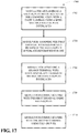
Fig. 9 , illustrated is amethodology 900 for half-duplex communication in an FDD system (e.g., system 200). It is to be appreciated thatmethodology 900 can be performed by one or more of a terminal (e.g., an access terminal 220) and a base station (e.g., access network 210).Methodology 900 begins atblock 902, wherein a half-duplex interlace to use for communication is determined from among multiple half-duplex interlaces, with each half-duplex interlace including temporally non-overlapping frames for the forward and reverse links. In accordance with one aspect, the forward link may be associated with a first frequency channel, and the reverse link may be associated with a second frequency channel. In accordance with another aspect, the multiple half-duplex interlaces include different frames such that each frame is included in only one half-duplex interlace. In a specific, non-limiting example, the multiple half-duplex interlaces can comprise a first half-duplex interlace and a second half-duplex interlace. The first half-duplex interlace can include every other frame for the forward link and every other frame for the reverse link, and the second half-duplex interlace can include the remaining frames for the forward and reverse links. It is to be appreciated that this example merely illustrates one way in which the multiple half-duplex interlaces may be defined and that other manners of defining the multiple half-duplex interlaces are possible. - Further, the half-duplex interlace to use for communication as determined in the act described in
block 902 may be determined based on an identifier (e.g., a MACID) for a terminal. In a specific, non-limiting example, terminals with odd MACIDs may be assigned a first half-duplex interlace, and terminals with even MACIDs may be assigned a second half-duplex interlace. It is to be appreciated that this example merely illustrates one way in which terminals may be assigned to the multiple half-duplex interlaces and that other ways are possible. - Upon completing the act represented in
block 902, the methodology continues to block 904, wherein a terminal or basestation employing methodology 900 communicates using frames of the half-duplex interlace determined for use. In one example, data may be received via a first frequency channel in forward link frames of the half-duplex interlace determined for use in the act described inblock 902. Additionally and/or alternatively, data may be sent via a second frequency channel in reverse link frames of the half-duplex interlace determined for use. In accordance with one aspect, data may be sent and/or received using H-ARQ transmission in a similar manner toretransmission structures transmission scheme 600. -
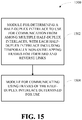
Fig. 10 illustrates amethodology 1000 for half-duplex communication in an FDD system (e.g., system 200).Methodology 1000 begins atblock 1002, wherein a transmission timeline (e.g., forwardlink transmission timeline 510 and reverse link transmission timeline 520) is partitioned into forward link and reverse link superframes (e.g.,forward link superframe 515 and reverse link superframe 525) having a superframe preamble and a predetermined number of frames. The methodology then continues to block 1004, wherein the frames in each forward link and reverse link superframe are allocated among a plurality of half-duplex interlaces (e.g., half-duplex interlace 0 and half-duplex interlace 1 illustrated by superframe structure 500). - Next, at
block 1006, an access terminal (e.g., an access terminal 220) is associated with a half-duplex interlace. In one example, an access terminal can be associated with a half-duplex interlace based on an identifier (e.g., a MACID) for the access terminal. In a specific, non-limiting example, access terminals with odd MACIDs may be associated with a first half-duplex interlace, and access terminals with even MACIDs may be associated with a second half-duplex interlace. It is to be appreciated that this example merely illustrates one way in which an access terminal may be associated with a half-duplex interlace and that other ways are possible. Further, it is to be appreciated that an access terminal can be associated with a half-duplex interlace by an access network (e.g., access network 210) or the access terminal itself. - Finally, at
block 1008, an access network communicates with the access terminal that was associated with a half-duplex interlace in the act described inblock 1006 using the frames that were allocated in the act described inblock 1004 for the half-duplex interlace associated with the access terminal. In one example, the access network and access terminal may communicate via a first frequency channel in forward link frames of the associated half-duplex interlace and via a second frequency channel in reverse link frames of the associated half-duplex interlace. In another example, the access network and access terminal may communicate using H-ARQ transmission in a similar manner toretransmission structures -
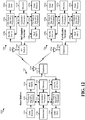
Fig. 11 illustrates amethodology 1100 for communicating with half-duplex and full-duplex terminals (e.g., access terminals 220) in an FDD system (e.g., system 200).Methodology 1100 begins atblock 1102, wherein a half-duplex interlace to use for communication with a first terminal is determined from among multiple half-duplex interlaces. Next, atblock 1104, the first terminal is assigned resources in frames of the half-duplex interlace determined for use in the act described inblock 1102. Themethodology 1100 then continues to block 1106, wherein a second terminal is assigned resources in any of the frames of the multiple half-duplex interlaces. - Upon completing the act described in
block 1106, themethodology 1100 proceeds to block 1108, wherein a base station (e.g., access network 210) communicates with the first terminal using half-duplex. In one example, the base station can exchange data with the first terminal in frames of the half-duplex interlace determined for use in the act described inblock 1102. Additionally, the base station can receive signaling from the first terminal in a CDMA control segment for this half-duplex interlace. Next, themethodology 1100 continues to block 1110, wherein the base station communicates with the second terminal using full-duplex. In one example, the base station can exchange data with the second terminal in any frame of the multiple half-duplex interlaces. Additionally, the base station can receive signaling from the second terminal in a CDMA control segment for one of the multiple half-duplex interlaces. - Referring now to
Fig. 12 , a block diagram illustrating an examplewireless communication system 1200 in which one or more embodiments described herein may function is provided. In accordance with one aspect, thesystem 1200 includes abase station 110, a half-duplex terminal 120x, and a full-duplex terminal 120y. In one example,base station 110 includes a transmit (TX) data andsignaling processor 1212 that can receive traffic data from adata source 1210 and signaling from a controller/processor 1230 and/or ascheduler 1234. The controller/processor 1230 can provide system information for a superframe preamble and/or signaling (e.g., ACKs, PC commands, erasure indicators, ...) for one or more terminals communicating withbase station 110, and thescheduler 1234 can provide assignments of resources (e.g., data channels, frames, and/or subcarriers) on the forward and/or reverse link for the terminals. Additionally, TX data andsignaling processor 1212 can process (e.g., encode, interleave, and/or symbol map) traffic data and signaling to respectively provide data symbols and signaling symbols.Base station 110 may further include a modulator (Mod) 1214 that multiplexes pilot symbols with the data and signaling symbols, performs modulation on the multiplexed symbols (e.g., for OFDMA and/or CDMA), and provides output chips. Further, a transmitter (TMTR) 1214 can condition (e.g., convert to analog, amplify, filter, and/or upconvert frequency) the output chips and generate a forward link signal. This forward link signal can then be routed through aduplexer 1216 and transmitted via anantenna 1218. - In another example, half-
duplex terminal 120x can include anantenna 1252x that receives the forward link signals from one or more base stations includingbase station 110. Half-duplex terminal 120x can also include a radio frequency (RF)switch 1254x that connectsantenna 1252x to a receiver (RCVR) 1256x during forward link frames and connectsantenna 1252x to atransmitter 1266x during reverse link frames. - Additionally and/or alternatively, full-
duplex terminal 120y can include anantenna 1252y that receives the forward link signals from one or more base stations includingbase station 110. Full-duplex terminal 120y can also include aduplexer 1254y that routes a received signal fromantenna 1252y to areceiver 1256y and further routes a reverse link signal from atransmitter 1266y toantenna 1252y. - Further, each terminal 120x and 120y can include a receiver 1256 that conditions (e.g., filters, amplifies, frequency downconverts, and/or digitizes) the received signal from antenna 1252 and provides samples.
Terminals terminals signaling processor 1212 andmodulator 1214, respectively, atbase station 110. - On the reverse link, a TX data and signaling processor 1264 at each terminal 120x and 120y can process traffic data from a data source 1262 and signaling from controller/processor 1270 and generate symbols. The symbols can then be modulated by a modulator 1266 and conditioned by transmitter 1266 to generate a reverse link signal. The reverse link signal can then be passed through
RF switch 1254x to be transmitted viaantenna 1252x in terminal 120x and/or routed throughduplexer 1254y to be transmitted viaantenna 1252y in terminal 120y. Atbase station 110, reverse link signals from one or moreterminals including terminals 120x and/or 120y can be received byantenna 1218, routed throughduplexer 1216, conditioned by areceiver 1220, demodulated by ademodulator 1220, and processed by an RX data andsignaling processor 1222. In one example, RX data andsignaling processor 1222 can provide decoded data to adata sink 1224 and detected signaling to controller/processor 1230. - In accordance with one aspect, controllers/
processors base station 110 andterminals processor 1230 can implementmethodologies methodologies memories base station 110 andterminals scheduler 1234 can schedule terminals communicating withbase station 110 and assign resources (e.g., data channels, frames, and/or subcarriers) to the scheduled terminals. -
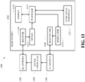
Fig. 13 is a block diagram of asystem 1300 that coordinates FDD half-duplex communication in accordance with various aspects described herein. In one example,system 1300 includes a base station oraccess point 1302. As illustrated,base station 1302 can receive signal(s) from one ormore access terminals 1304 via a receive (Rx)antenna 1306 and transmit to the one ormore user devices 1304 via a transmit (Tx)antenna 1308. - Additionally,
base station 1302 can comprise areceiver 1310 that receives information from receiveantenna 1306. In one example, thereceiver 1310 can be operatively associated with a demodulator (Demod) 1312 that demodulates received information. Demodulated symbols can then be analyzed by aprocessor 1314.Processor 1314 can be coupled tomemory 1316, which can store information related to code clusters, access terminal assignments, lookup tables related thereto, unique scrambling sequences, and/or other suitable types of information. Additionally and/or alternatively,processor 1314 can be coupled to aninterlacing component 1322, which can facilitate the creation of half-duplex interlaces from a transmission timeline (e.g., forwardlink transmission timeline 510 and reverse link transmission timeline 520) and or the assignment of one ormore access terminals 1304 to one or more half-duplex interlaces. In one example,base station 1302 can employinterlace component 1322 to performmethodologies processor 1314.Base station 1302 can also include amodulator 1318 that can multiplex a signal for transmission by atransmitter 1320 through transmitantenna 1308 to one ormore access terminals 1304. -
Fig. 14 is a block diagram of a system 1400 that coordinates FDD half-duplex communication in accordance with various aspects described herein. In one example, system 1400 includes anaccess terminal 1402. As illustrated,access terminal 1402 can receive signal(s) from one ormore base stations 1404 and transmit to the one ormore base stations 1404 via anantenna 1408. In one example, whether the antenna is operable to receive or transmit data at a given time is controlled by anRF switch 1406. - Additionally,
access terminal 1402 can comprise areceiver 1410 that receives information fromantenna 1408. In one example, thereceiver 1410 can be operatively associated with a demodulator (Demod) 1412 that demodulates received information. Demodulated symbols can then be analyzed by aprocessor 1414.Processor 1414 can be coupled tomemory 1416, which can store data and/or program codes related toaccess terminal 1402. Additionally and/or alternatively,processor 1414 can be coupled to aninterlacing component 1422, which can facilitate the assignment ofaccess terminal 1402 to a half-duplex interlace created by one ormore base stations 1404. In one example,access terminal 1402 can employinterlace component 1422 to performmethodologies processor 1414.Access terminal 1402 can also include amodulator 1418 that can multiplex a signal for transmission by atransmitter 1420 throughantenna 1408 to one ormore base stations 1404. -
Fig. 15 illustrates asystem 1500 that facilitates half-duplex communication in an FDD system. It is to be appreciated thatsystem 1500 is represented as including functional blocks, which can be functional blocks that represent functions implemented by a processor, software, or combination thereof (e.g., firmware).System 1500 can be implemented in a base station (e.g., access network 210) or a terminal (e.g., access terminal 220) and can include a module for determining a half-duplex interlace to use for communication from among multiple half-duplex interlaces 1502. Further,system 1500 can include a module for communicating using frames of the half-duplex interlace determined foruse 1504. -
Fig. 16 illustrates asystem 1600 that facilitates half-duplex communication in an FDD system.System 1600 is represented as including functional blocks, which can be functional blocks that represent functions implemented by a processor, software, or combination thereof (e.g., firmware).System 1600 can be implemented in a base station (e.g., access network 210) or a terminal (e.g., access terminal 220) and can include a module for partitioning a transmission timeline into forward link and reverse link superframes having a superframe preamble and a predetermined number offrames 1602, a module for allocating frames in each forward link and reverse link superframe among a plurality of half-duplex interlaces 1604, a module for associating an access terminal with a half-duplex interlace 1606, and a module for communicating with the access terminal using the frames allocated for the associated half-duplex interlace 1608. -
Fig. 17 illustrates asystem 1700 that facilitates communication with half-duplex and full-duplex terminals in an FDD system.System 1700 is represented as including functional blocks, which can be functional blocks that represent functions implemented by a processor, software, or combination thereof (e.g., firmware).System 1700 can be implemented in a base station (e.g., access network 210) and can include a module for determining a half-duplex interlace to use for communication with a first terminal from among multiple half-duplex interlaces 1702, a module for assigning the first terminal with resources in frames of the half-duplex interlace determined foruse 1704, a module for assigning a second terminal with resources in any of the frames of the multiple half-duplex interlaces 1706, a module for communicating with the first terminal using half-duplex 1708, and a module for communicating with the second terminal using full-duplex 1710. - It is to be understood that the embodiments described herein may be implemented by hardware, software, firmware, middleware, microcode, or any combination thereof. When the systems and/or methods are implemented in software, firmware, middleware or microcode, program code or code segments, they may be stored in a machine-readable medium, such as a storage component. A code segment may represent a procedure, a function, a subprogram, a program, a routine, a subroutine, a module, a software package, a class, or any combination of instructions, data structures, or program statements. A code segment may be coupled to another code segment or a hardware circuit by passing and/or receiving information, data, arguments, parameters, or memory contents. Information, arguments, parameters, data, etc. may be passed, forwarded, or transmitted using any suitable means including memory sharing, message passing, token passing, network transmission, etc.
- For a software implementation, the techniques described herein may be implemented with modules (e.g., procedures, functions, and so on) that perform the functions described herein. The software codes may be stored in memory units and executed by processors. The memory unit may be implemented within the processor or external to the processor, in which case it can be communicatively coupled to the processor via various means as is known in the art.
- What has been described above includes examples of one or more embodiments. It is, of course, not possible to describe every conceivable combination of components or methodologies for purposes of describing the aforementioned embodiments, but one of ordinary skill in the art may recognize that many further combinations and permutations of various embodiments are possible. Accordingly, the described embodiments are intended to embrace all such alterations, modifications and variations that fall within the scope of the appended claims.
Claims (14)
- A method for half-duplex frequency division duplex, FDD communication in a wireless communication system, comprising:determining a half-duplex interlace to use for communication from among a plurality of temporally complementary half-duplex interlaces, wherein each half-duplex interlace in the plurality of half-duplex interlaces comprises a sequence of temporally non-overlapping frames for a forward link and a reverse link; andcommunicating using frames of the half-duplex interlace determined for use,wherein the forward link is associated with a first frequency channel comprising a plurality of frequency subbands, and the reverse link is associated with a second frequency channel comprising a plurality of frequency subbands.
- The method of claim 1, wherein the determining a half-duplex interlace to use includes determining the half-duplex interlace to use for communication based on an identifier for a terminal, wherein the identifier is preferably a Medium Access Control Identifier (MACID) for a terminal.
- The method of claim 2, wherein the communicating using frames of the half-duplex interlace determined for use includes:receiving data via the first frequency channel in forward link frames of the half-duplex interlace determined for use; andsending data via the second frequency channel in reverse link frames of the half-duplex interlace determined for use.
- The method of claim 1, wherein the communicating using frames of the half-duplex interlace determined for use comprises receiving a control segment that spans one of the plurality of subbands on the reverse link, wherein the receiving a control segment comprises receiving signaling on the reverse link, wherein the control segment comprises one or more of a CDMA control segment and an OFDMA control segment for the half-duplex interlace. determined for use.
- The method of claim 4, wherein the sending signaling on the forward link comprises one or more of sending at least one power control command on a forward link dedicated power control channel (F-PCCH) and sending at least one pilot quality indicator on a forward link pilot quality indicator channel (F-PQICH).
- The method of claim 4, wherein the sending signaling on the forward link comprises sending interference information on one or more of a forward link interference over thermal channel (F-IOTCH) and a forward link fast other sector interference channel (F-FOSICH).
- The method of claim 4, wherein the sending signaling on the forward link comprises sending signaling on a forward link shared control channel (F-SCCH).
- The method of claim 4, wherein the sending signaling on the forward link comprises sending at least one pilot on one or more of a forward link CQI pilot channel (F-CQIPICH) and a forward link beacon pilot channel (F-BPICH).
- An apparatus for half-duplex frequency division duplex, FDD communication in a wireless communication system, comprising:means for determining a half-duplex interlace to use for communication from among a plurality of temporally complementary half-duplex interlaces, wherein each half-duplex interlace in the plurality of half-duplex interlaces comprises a sequence of temporally non-overlapping frames for a forward link and a reverse link; andmeans for communicating using frames of the half-duplex interlace determined for use,wherein the forward link is associated with a first frequency channel comprising a plurality of frequency subbands, and the reverse link is associated with a second frequency channel comprising a plurality of frequency subbands.
- The apparatus of claim 9, wherein the means for communicating using frames of the half-duplex interlace determined for use includes:means for communicating with a first terminal using half-duplex; andmeans for communicating with a second terminal using full-duplex.
- A computer-readable medium having stored thereon computer-executable instructions for half-duplex communication in a wireless communication system, the instructions comprising instructions for carrying out the steps of any of claims 1 to 8.
- A processor that executes computer-executable instructions for half-duplex communication in a wireless communication system, the instructions comprising instructions for carrying out the steps of any of claims 1 to 8.
- The method of claim 1, wherein each of the plurality of half-duplex interlaces further comprises a preamble frame for the forward link, wherein the preamble frame is shared by each of the plurality of half-duplex interlaces.
- The method of claim 1, wherein the communicating using frames of the half-duplex interlace determined for use further comprises:assigning a first terminal with resources in frames of the half-duplex interlace determined for use;assigning a second terminal with resources in any frames of the plurality of half-duplex interlaces;communicating with the first terminal using half-duplex; andcommunicating with the second terminal using full-duplex.
Applications Claiming Priority (2)
| Application Number | Priority Date | Filing Date | Title |
|---|---|---|---|
| US80176306P | 2006-05-18 | 2006-05-18 | |
| PCT/US2007/069291 WO2007137191A2 (en) | 2006-05-18 | 2007-05-18 | Half-duplex communication in a frequency division duplex system |
Publications (2)
| Publication Number | Publication Date |
|---|---|
| EP2018719A2 EP2018719A2 (en) | 2009-01-28 |
| EP2018719B1 true EP2018719B1 (en) | 2017-07-05 |
Family
ID=38704733
Family Applications (1)
| Application Number | Title | Priority Date | Filing Date |
|---|---|---|---|
| EP07783953.8A Active EP2018719B1 (en) | 2006-05-18 | 2007-05-18 | Half-duplex communication in a frequency division duplex system |
Country Status (11)
| Country | Link |
|---|---|
| US (1) | US8305943B2 (en) |
| EP (1) | EP2018719B1 (en) |
| JP (1) | JP5027219B2 (en) |
| KR (1) | KR101046919B1 (en) |
| CN (1) | CN101444016B (en) |
| BR (1) | BRPI0711576B1 (en) |
| CA (1) | CA2650407C (en) |
| ES (1) | ES2638428T3 (en) |
| RU (1) | RU2408984C2 (en) |
| TW (1) | TWI362853B (en) |
| WO (1) | WO2007137191A2 (en) |
Families Citing this family (44)
| Publication number | Priority date | Publication date | Assignee | Title |
|---|---|---|---|---|
| CA2656892C (en) | 2006-07-07 | 2012-11-27 | Lg Electronics Inc. | A method of utilizing resources efficiently in a reverse link transmission |
| CN103067141B (en) | 2006-10-31 | 2015-11-18 | 艾利森电话股份有限公司 | HARQ in spatial multiplexing MIMO system |
| US8422411B2 (en) * | 2007-10-07 | 2013-04-16 | Motorola Mobility Llc | Flexible frame structure in wireless communication system |
| US8310961B2 (en) * | 2007-10-08 | 2012-11-13 | Nokia Siemens Networks Oy | Techniques for link utilization for half-duplex and full-duplex stations in a wireless network |
| US8155032B2 (en) * | 2007-11-16 | 2012-04-10 | Telefonaktiebolaget Lm Ericsson (Publ) | Adaptive scheduling for half-duplex wireless terminals |
| KR101447210B1 (en) | 2007-11-30 | 2014-10-07 | 삼성전자주식회사 | Apparatus and method for frame structure in wireless communication system |
| KR101391727B1 (en) | 2007-12-27 | 2014-05-07 | 삼성전자주식회사 | Apparatus and method for constructing a frame in a communication system |
| US7953028B2 (en) * | 2008-01-14 | 2011-05-31 | Telefonaktiebolaget Lm Ericsson (Publ) | Methods and apparatus for improved receiver performance in half-duplex wireless terminals |
| US9118465B2 (en) * | 2008-02-21 | 2015-08-25 | Google Technology Holdings LLC | Method for supporting flexible frame structures in wireless communication systems |
| KR101481052B1 (en) * | 2008-10-13 | 2015-01-12 | 삼성전자주식회사 | Apparatus and method for transmitting and receiving control information in a broadband wireless communication system using half frequency division duplex |
| US9118468B2 (en) | 2009-07-23 | 2015-08-25 | Qualcomm Incorporated | Asynchronous time division duplex operation in a wireless network |
| CN102014514B (en) * | 2009-11-10 | 2014-01-15 | 电信科学技术研究院 | Method and equipment for obtaining duplex system information of user equipment |
| GB2485387B (en) | 2010-11-12 | 2013-10-02 | Intellectual Ventures Holding 81 Llc | Wireless communication system, communication unit, and method for scheduling |
| US9014110B2 (en) * | 2011-07-18 | 2015-04-21 | Qualcomm Incorporated | Enabling half-duplex operation |
| US9763239B2 (en) | 2012-01-29 | 2017-09-12 | Lg Electronics Inc. | Data transmission method and apparatus for half-duplex devices |
| CN103945554B (en) * | 2013-01-21 | 2020-07-24 | 华为技术有限公司 | User equipment scheduling method and device under full-duplex cellular network |
| US9179336B2 (en) | 2013-02-19 | 2015-11-03 | Mimosa Networks, Inc. | WiFi management interface for microwave radio and reset to factory defaults |
| US9930592B2 (en) | 2013-02-19 | 2018-03-27 | Mimosa Networks, Inc. | Systems and methods for directing mobile device connectivity |
| WO2014137370A1 (en) | 2013-03-06 | 2014-09-12 | Mimosa Networks, Inc. | Waterproof apparatus for cables and cable interfaces |
| WO2014138292A1 (en) | 2013-03-06 | 2014-09-12 | Mimosa Networks, Inc. | Enclosure for radio, parabolic dish antenna, and side lobe shields |
| US10742275B2 (en) | 2013-03-07 | 2020-08-11 | Mimosa Networks, Inc. | Quad-sector antenna using circular polarization |
| US9191081B2 (en) | 2013-03-08 | 2015-11-17 | Mimosa Networks, Inc. | System and method for dual-band backhaul radio |
| WO2014189301A1 (en) * | 2013-05-22 | 2014-11-27 | 엘지전자 주식회사 | Structure of full duplex radio region applied in radio access system supporting full duplex radio scheme, and method and apparatus for allocating same |
| US9295103B2 (en) | 2013-05-30 | 2016-03-22 | Mimosa Networks, Inc. | Wireless access points providing hybrid 802.11 and scheduled priority access communications |
| US10938110B2 (en) | 2013-06-28 | 2021-03-02 | Mimosa Networks, Inc. | Ellipticity reduction in circularly polarized array antennas |
| US9929851B2 (en) * | 2013-09-16 | 2018-03-27 | Qualcomm, Incorporated | System and methods for full duplex communication over a wireless network |
| US9264205B2 (en) * | 2013-10-22 | 2016-02-16 | Qualcomm Incorporated | Full duplex communication in the presence of mixed full and half duplex users |
| WO2015109503A1 (en) | 2014-01-23 | 2015-07-30 | 华为技术有限公司 | Terminal scheduling method, station and terminal |
| US9001689B1 (en) * | 2014-01-24 | 2015-04-07 | Mimosa Networks, Inc. | Channel optimization in half duplex communications systems |
| US9780892B2 (en) | 2014-03-05 | 2017-10-03 | Mimosa Networks, Inc. | System and method for aligning a radio using an automated audio guide |
| US9998246B2 (en) | 2014-03-13 | 2018-06-12 | Mimosa Networks, Inc. | Simultaneous transmission on shared channel |
| WO2015160168A1 (en) * | 2014-04-14 | 2015-10-22 | 엘지전자 주식회사 | Method and apparatus for retransmitting scheduling assignment information in wireless communication system supporting device to device (d2d) communication |
| US9954663B2 (en) * | 2014-05-09 | 2018-04-24 | Huawei Technologies Co., Ltd. | System and method for orthogonal frequency division multiple access communications |
| KR102277257B1 (en) * | 2014-05-19 | 2021-07-14 | 엘지전자 주식회사 | Apparatus and method of performing communication in a system supporting full-duplex communication and Half-duplex communication |
| US10958332B2 (en) | 2014-09-08 | 2021-03-23 | Mimosa Networks, Inc. | Wi-Fi hotspot repeater |
| USD752566S1 (en) | 2014-09-12 | 2016-03-29 | Mimosa Networks, Inc. | Wireless repeater |
| US10834763B2 (en) * | 2015-11-04 | 2020-11-10 | Lg Electronics Inc. | Method and apparatus for handling overlap of different channels in wireless communication system |
| WO2017123558A1 (en) | 2016-01-11 | 2017-07-20 | Mimosa Networks, Inc. | Printed circuit board mounted antenna and waveguide interface |
| CN109156022B (en) | 2016-06-22 | 2022-08-09 | 英特尔公司 | Communication device and method for full duplex scheduling |
| US11251539B2 (en) | 2016-07-29 | 2022-02-15 | Airspan Ip Holdco Llc | Multi-band access point antenna array |
| US10873437B2 (en) * | 2016-08-11 | 2020-12-22 | Sharp Kabushiki Kaisha | Systems and methods for frequency-division duplex transmission time interval operation |
| US10511074B2 (en) | 2018-01-05 | 2019-12-17 | Mimosa Networks, Inc. | Higher signal isolation solutions for printed circuit board mounted antenna and waveguide interface |
| WO2019168800A1 (en) | 2018-03-02 | 2019-09-06 | Mimosa Networks, Inc. | Omni-directional orthogonally-polarized antenna system for mimo applications |
| US11289821B2 (en) | 2018-09-11 | 2022-03-29 | Air Span Ip Holdco Llc | Sector antenna systems and methods for providing high gain and high side-lobe rejection |
Family Cites Families (24)
| Publication number | Priority date | Publication date | Assignee | Title |
|---|---|---|---|---|
| CA1300289C (en) | 1987-10-27 | 1992-05-05 | Paul Anton Nysen | Passive universal communicator |
| US5499243A (en) * | 1993-01-22 | 1996-03-12 | Hall; Dennis R. | Method and apparatus for coordinating transfer of information between a base station and a plurality of radios |
| FR2718907B1 (en) * | 1994-04-15 | 1996-05-24 | Alcatel Mobile Comm France | AMRF process with frame-multiframe structure and corresponding signal. |
| US6256301B1 (en) * | 1998-10-15 | 2001-07-03 | Qualcomm Incorporated | Reservation multiple access |
| US6628626B1 (en) * | 1999-07-02 | 2003-09-30 | Lucent Technologies Inc. | Wireless data communications using asymmetric channel allocation |
| AU2001288828A1 (en) | 2000-09-14 | 2002-03-26 | Ensemble Communications, Inc. | A system and method for wireless communication in a frequency division duplexingregion |
| AU2002213703A1 (en) * | 2000-10-24 | 2002-05-06 | Nortel Networks Limited | Shared channel structure, arq systems and methods |
| CA2467700C (en) * | 2000-11-15 | 2012-03-20 | Ensemble Communications, Inc. | Improved frame structure for a communication system using adaptive modulation |
| JP4703863B2 (en) | 2001-01-31 | 2011-06-15 | 東芝機械株式会社 | Deviation type rolling guide deviation correction method and apparatus |
| JP2003045042A (en) | 2001-07-31 | 2003-02-14 | Toshiba Corp | Thickness irregularity correction method for information recording medium and information recording and reproducing device using thickness irregularity correction method |
| EP1520376B1 (en) * | 2002-06-27 | 2009-06-24 | Nokia Corporation | Scheduling method and apparatus for half-duplex transmission |
| KR20040017909A (en) * | 2002-08-22 | 2004-03-02 | 광주과학기술원 | Method of Interlaced Frequency Division Duplexing for Duplexing Communication System |
| US7633894B2 (en) * | 2002-09-05 | 2009-12-15 | The Regents Of The University Of California | Scheduling methods for wireless networks |
| EP1627476B1 (en) | 2003-05-27 | 2015-10-21 | TELEFONAKTIEBOLAGET LM ERICSSON (publ) | Scheduler and method of scheduling data for communication between a node station and plurality of radio terminals |
| EP1492269B1 (en) | 2003-06-25 | 2007-02-14 | Siemens S.p.A. | Bandwidth allocation for the uplink of a point-to-multipoint radio system with adaptive coding and modulation of physical channels (adaptive PHY mode) |
| JP2005065207A (en) | 2003-07-30 | 2005-03-10 | Kobe Steel Ltd | Radio communication apparatus |
| CN1622653A (en) * | 2003-11-28 | 2005-06-01 | 皇家飞利浦电子股份有限公司 | Apparatus and method for frequency estimation of TD-SCDMA system downlink |
| US7420950B2 (en) * | 2004-04-05 | 2008-09-02 | Dspg Ltd. | Multiplex communication with slotted retransmission on demand |
| TWI270905B (en) | 2004-07-14 | 2007-01-11 | Sanyo Electric Co | Solid electrolytic condenser and manufacturing method of the same |
| IL165035A (en) * | 2004-11-04 | 2011-06-30 | Alvarion Ltd | Method and device for incorporating different mode wireless transmissions |
| US7626955B2 (en) * | 2005-05-02 | 2009-12-01 | Nokia Corporation | System and method for providing a fast and optimized uplink and downlink scheduling algorithm for use in FDD communication systems with half-duplex stations |
| US7564822B2 (en) * | 2005-05-19 | 2009-07-21 | Alcatel-Lucent Usa Inc. | Method of reverse link transmission in a wireless network using code and frequency multiplexing |
| US20060280141A1 (en) * | 2005-06-08 | 2006-12-14 | Mcbeath Sean M | Apparatus and method for sharing a unique identifier among a plurality of receivers |
| GB2431073B (en) * | 2005-10-10 | 2008-05-14 | Ipwireless Inc | Cellular communication system and method for co-existence of dissimilar systems |
-
2007
- 2007-05-15 US US11/748,878 patent/US8305943B2/en active Active
- 2007-05-18 KR KR1020087030835A patent/KR101046919B1/en active IP Right Grant
- 2007-05-18 CN CN2007800177705A patent/CN101444016B/en active Active
- 2007-05-18 CA CA2650407A patent/CA2650407C/en active Active
- 2007-05-18 WO PCT/US2007/069291 patent/WO2007137191A2/en active Application Filing
- 2007-05-18 RU RU2008149946/09A patent/RU2408984C2/en active
- 2007-05-18 ES ES07783953.8T patent/ES2638428T3/en active Active
- 2007-05-18 JP JP2009511254A patent/JP5027219B2/en active Active
- 2007-05-18 TW TW096117859A patent/TWI362853B/en active
- 2007-05-18 BR BRPI0711576A patent/BRPI0711576B1/en active IP Right Grant
- 2007-05-18 EP EP07783953.8A patent/EP2018719B1/en active Active
Also Published As
| Publication number | Publication date |
|---|---|
| CA2650407C (en) | 2013-07-30 |
| EP2018719A2 (en) | 2009-01-28 |
| CN101444016A (en) | 2009-05-27 |
| RU2408984C2 (en) | 2011-01-10 |
| US8305943B2 (en) | 2012-11-06 |
| ES2638428T3 (en) | 2017-10-20 |
| KR101046919B1 (en) | 2011-07-07 |
| RU2008149946A (en) | 2010-06-27 |
| US20070268848A1 (en) | 2007-11-22 |
| JP2009538063A (en) | 2009-10-29 |
| CN101444016B (en) | 2013-11-06 |
| WO2007137191A3 (en) | 2008-02-14 |
| JP5027219B2 (en) | 2012-09-19 |
| TWI362853B (en) | 2012-04-21 |
| TW200807941A (en) | 2008-02-01 |
| BRPI0711576A2 (en) | 2011-11-16 |
| KR20090017612A (en) | 2009-02-18 |
| WO2007137191A2 (en) | 2007-11-29 |
| CA2650407A1 (en) | 2007-11-29 |
| BRPI0711576B1 (en) | 2020-01-14 |
Similar Documents
| Publication | Publication Date | Title |
|---|---|---|
| EP2018719B1 (en) | Half-duplex communication in a frequency division duplex system | |
| US11777750B2 (en) | Terminal and communication method | |
| JP6121587B2 (en) | PUCCH resource allocation for carrier aggregation in LTE Advanced | |
| US9107210B2 (en) | Resource allocation | |
| JP5083580B2 (en) | Communications system | |
| CN112930658A (en) | Method and apparatus for performing HARQ feedback process in NR V2X system | |
| EP2039202B1 (en) | Resource allocation for co-existin networks | |
| US8396013B2 (en) | Method and apparatus for supporting half-duplex terminals in an asynchronous mode | |
| US20070230406A1 (en) | Apparatus and method for transmitting/receiving packet data in a mobile communication system | |
| KR20140014311A (en) | Method and apparatus for transmitting and receiving ack/nack information in mobile communication system | |
| KR20190139624A (en) | Method and apparatus of indicating information related to dmrs for v2x in new radio system | |
| WO2011148984A1 (en) | Wireless base station and method for controlling the same | |
| JP4927946B2 (en) | Method and apparatus for supporting half-duplex terminals in asynchronous mode | |
| CN108432279B (en) | Cellular communication system apparatus |
Legal Events
| Date | Code | Title | Description |
|---|---|---|---|
| PUAI | Public reference made under article 153(3) epc to a published international application that has entered the european phase |
Free format text: ORIGINAL CODE: 0009012 |
|
| 17P | Request for examination filed |
Effective date: 20081114 |
|
| AK | Designated contracting states |
Kind code of ref document: A2 Designated state(s): AT BE BG CH CY CZ DE DK EE ES FI FR GB GR HU IE IS IT LI LT LU LV MC MT NL PL PT RO SE SI SK TR |
|
| RIN1 | Information on inventor provided before grant (corrected) |
Inventor name: KHANDEKAR, AAMODC/O QUALCOMM INCORPORATED Inventor name: BHUSHAN, NAGA |
|
| DAX | Request for extension of the european patent (deleted) | ||
| 17Q | First examination report despatched |
Effective date: 20100520 |
|
| GRAP | Despatch of communication of intention to grant a patent |
Free format text: ORIGINAL CODE: EPIDOSNIGR1 |
|
| INTG | Intention to grant announced |
Effective date: 20170120 |
|
| GRAS | Grant fee paid |
Free format text: ORIGINAL CODE: EPIDOSNIGR3 |
|
| GRAA | (expected) grant |
Free format text: ORIGINAL CODE: 0009210 |
|
| AK | Designated contracting states |
Kind code of ref document: B1 Designated state(s): AT BE BG CH CY CZ DE DK EE ES FI FR GB GR HU IE IS IT LI LT LU LV MC MT NL PL PT RO SE SI SK TR |
|
| REG | Reference to a national code |
Ref country code: GB Ref legal event code: FG4D |
|
| REG | Reference to a national code |
Ref country code: CH Ref legal event code: EP |
|
| REG | Reference to a national code |
Ref country code: AT Ref legal event code: REF Ref document number: 907260 Country of ref document: AT Kind code of ref document: T Effective date: 20170715 |
|
| REG | Reference to a national code |
Ref country code: IE Ref legal event code: FG4D |
|
| REG | Reference to a national code |
Ref country code: DE Ref legal event code: R096 Ref document number: 602007051552 Country of ref document: DE |
|
| REG | Reference to a national code |
Ref country code: NL Ref legal event code: FP |
|
| REG | Reference to a national code |
Ref country code: ES Ref legal event code: FG2A Ref document number: 2638428 Country of ref document: ES Kind code of ref document: T3 Effective date: 20171020 |
|
| REG | Reference to a national code |
Ref country code: AT Ref legal event code: MK05 Ref document number: 907260 Country of ref document: AT Kind code of ref document: T Effective date: 20170705 |
|
| REG | Reference to a national code |
Ref country code: LT Ref legal event code: MG4D |
|
| REG | Reference to a national code |
Ref country code: HU Ref legal event code: AG4A Ref document number: E034120 Country of ref document: HU |
|
| PG25 | Lapsed in a contracting state [announced via postgrant information from national office to epo] |
Ref country code: AT Free format text: LAPSE BECAUSE OF FAILURE TO SUBMIT A TRANSLATION OF THE DESCRIPTION OR TO PAY THE FEE WITHIN THE PRESCRIBED TIME-LIMIT Effective date: 20170705 Ref country code: SE Free format text: LAPSE BECAUSE OF FAILURE TO SUBMIT A TRANSLATION OF THE DESCRIPTION OR TO PAY THE FEE WITHIN THE PRESCRIBED TIME-LIMIT Effective date: 20170705 Ref country code: LT Free format text: LAPSE BECAUSE OF FAILURE TO SUBMIT A TRANSLATION OF THE DESCRIPTION OR TO PAY THE FEE WITHIN THE PRESCRIBED TIME-LIMIT Effective date: 20170705 |
|
| PG25 | Lapsed in a contracting state [announced via postgrant information from national office to epo] |
Ref country code: LV Free format text: LAPSE BECAUSE OF FAILURE TO SUBMIT A TRANSLATION OF THE DESCRIPTION OR TO PAY THE FEE WITHIN THE PRESCRIBED TIME-LIMIT Effective date: 20170705 Ref country code: BG Free format text: LAPSE BECAUSE OF FAILURE TO SUBMIT A TRANSLATION OF THE DESCRIPTION OR TO PAY THE FEE WITHIN THE PRESCRIBED TIME-LIMIT Effective date: 20171005 Ref country code: IS Free format text: LAPSE BECAUSE OF FAILURE TO SUBMIT A TRANSLATION OF THE DESCRIPTION OR TO PAY THE FEE WITHIN THE PRESCRIBED TIME-LIMIT Effective date: 20171105 Ref country code: PL Free format text: LAPSE BECAUSE OF FAILURE TO SUBMIT A TRANSLATION OF THE DESCRIPTION OR TO PAY THE FEE WITHIN THE PRESCRIBED TIME-LIMIT Effective date: 20170705 Ref country code: GR Free format text: LAPSE BECAUSE OF FAILURE TO SUBMIT A TRANSLATION OF THE DESCRIPTION OR TO PAY THE FEE WITHIN THE PRESCRIBED TIME-LIMIT Effective date: 20171006 |
|
| REG | Reference to a national code |
Ref country code: DE Ref legal event code: R097 Ref document number: 602007051552 Country of ref document: DE |
|
| REG | Reference to a national code |
Ref country code: FR Ref legal event code: PLFP Year of fee payment: 12 |
|
| PG25 | Lapsed in a contracting state [announced via postgrant information from national office to epo] |
Ref country code: DK Free format text: LAPSE BECAUSE OF FAILURE TO SUBMIT A TRANSLATION OF THE DESCRIPTION OR TO PAY THE FEE WITHIN THE PRESCRIBED TIME-LIMIT Effective date: 20170705 Ref country code: RO Free format text: LAPSE BECAUSE OF FAILURE TO SUBMIT A TRANSLATION OF THE DESCRIPTION OR TO PAY THE FEE WITHIN THE PRESCRIBED TIME-LIMIT Effective date: 20170705 Ref country code: CZ Free format text: LAPSE BECAUSE OF FAILURE TO SUBMIT A TRANSLATION OF THE DESCRIPTION OR TO PAY THE FEE WITHIN THE PRESCRIBED TIME-LIMIT Effective date: 20170705 |
|
| PLBE | No opposition filed within time limit |
Free format text: ORIGINAL CODE: 0009261 |
|
| STAA | Information on the status of an ep patent application or granted ep patent |
Free format text: STATUS: NO OPPOSITION FILED WITHIN TIME LIMIT |
|
| PG25 | Lapsed in a contracting state [announced via postgrant information from national office to epo] |
Ref country code: SK Free format text: LAPSE BECAUSE OF FAILURE TO SUBMIT A TRANSLATION OF THE DESCRIPTION OR TO PAY THE FEE WITHIN THE PRESCRIBED TIME-LIMIT Effective date: 20170705 Ref country code: EE Free format text: LAPSE BECAUSE OF FAILURE TO SUBMIT A TRANSLATION OF THE DESCRIPTION OR TO PAY THE FEE WITHIN THE PRESCRIBED TIME-LIMIT Effective date: 20170705 |
|
| 26N | No opposition filed |
Effective date: 20180406 |
|
| PG25 | Lapsed in a contracting state [announced via postgrant information from national office to epo] |
Ref country code: SI Free format text: LAPSE BECAUSE OF FAILURE TO SUBMIT A TRANSLATION OF THE DESCRIPTION OR TO PAY THE FEE WITHIN THE PRESCRIBED TIME-LIMIT Effective date: 20170705 |
|
| REG | Reference to a national code |
Ref country code: CH Ref legal event code: PL |
|
| REG | Reference to a national code |
Ref country code: BE Ref legal event code: MM Effective date: 20180531 |
|
| PG25 | Lapsed in a contracting state [announced via postgrant information from national office to epo] |
Ref country code: MC Free format text: LAPSE BECAUSE OF FAILURE TO SUBMIT A TRANSLATION OF THE DESCRIPTION OR TO PAY THE FEE WITHIN THE PRESCRIBED TIME-LIMIT Effective date: 20170705 |
|
| REG | Reference to a national code |
Ref country code: IE Ref legal event code: MM4A |
|
| PG25 | Lapsed in a contracting state [announced via postgrant information from national office to epo] |
Ref country code: CH Free format text: LAPSE BECAUSE OF NON-PAYMENT OF DUE FEES Effective date: 20180531 Ref country code: LI Free format text: LAPSE BECAUSE OF NON-PAYMENT OF DUE FEES Effective date: 20180531 |
|
| PG25 | Lapsed in a contracting state [announced via postgrant information from national office to epo] |
Ref country code: LU Free format text: LAPSE BECAUSE OF NON-PAYMENT OF DUE FEES Effective date: 20180518 |
|
| PG25 | Lapsed in a contracting state [announced via postgrant information from national office to epo] |
Ref country code: IE Free format text: LAPSE BECAUSE OF NON-PAYMENT OF DUE FEES Effective date: 20180518 |
|
| PG25 | Lapsed in a contracting state [announced via postgrant information from national office to epo] |
Ref country code: BE Free format text: LAPSE BECAUSE OF NON-PAYMENT OF DUE FEES Effective date: 20180531 |
|
| PG25 | Lapsed in a contracting state [announced via postgrant information from national office to epo] |
Ref country code: MT Free format text: LAPSE BECAUSE OF NON-PAYMENT OF DUE FEES Effective date: 20180518 |
|
| PG25 | Lapsed in a contracting state [announced via postgrant information from national office to epo] |
Ref country code: TR Free format text: LAPSE BECAUSE OF FAILURE TO SUBMIT A TRANSLATION OF THE DESCRIPTION OR TO PAY THE FEE WITHIN THE PRESCRIBED TIME-LIMIT Effective date: 20170705 |
|
| PG25 | Lapsed in a contracting state [announced via postgrant information from national office to epo] |
Ref country code: PT Free format text: LAPSE BECAUSE OF FAILURE TO SUBMIT A TRANSLATION OF THE DESCRIPTION OR TO PAY THE FEE WITHIN THE PRESCRIBED TIME-LIMIT Effective date: 20170705 |
|
| PG25 | Lapsed in a contracting state [announced via postgrant information from national office to epo] |
Ref country code: CY Free format text: LAPSE BECAUSE OF FAILURE TO SUBMIT A TRANSLATION OF THE DESCRIPTION OR TO PAY THE FEE WITHIN THE PRESCRIBED TIME-LIMIT Effective date: 20170705 |
|
| PGFP | Annual fee paid to national office [announced via postgrant information from national office to epo] |
Ref country code: NL Payment date: 20230227 Year of fee payment: 17 |
|
| PGFP | Annual fee paid to national office [announced via postgrant information from national office to epo] |
Ref country code: FR Payment date: 20230223 Year of fee payment: 17 |
|
| PGFP | Annual fee paid to national office [announced via postgrant information from national office to epo] |
Ref country code: IT Payment date: 20230512 Year of fee payment: 17 Ref country code: ES Payment date: 20230608 Year of fee payment: 17 Ref country code: DE Payment date: 20230223 Year of fee payment: 17 |
|
| PGFP | Annual fee paid to national office [announced via postgrant information from national office to epo] |
Ref country code: HU Payment date: 20230421 Year of fee payment: 17 Ref country code: FI Payment date: 20230426 Year of fee payment: 17 |
|
| PGFP | Annual fee paid to national office [announced via postgrant information from national office to epo] |
Ref country code: GB Payment date: 20230412 Year of fee payment: 17 |