EP2018581B1 - Apparatus and method for recognizing objects - Google Patents
Apparatus and method for recognizing objects Download PDFInfo
- Publication number
- EP2018581B1 EP2018581B1 EP07725086A EP07725086A EP2018581B1 EP 2018581 B1 EP2018581 B1 EP 2018581B1 EP 07725086 A EP07725086 A EP 07725086A EP 07725086 A EP07725086 A EP 07725086A EP 2018581 B1 EP2018581 B1 EP 2018581B1
- Authority
- EP
- European Patent Office
- Prior art keywords
- wall
- light source
- light
- laser light
- mirror device
- Prior art date
- Legal status (The legal status is an assumption and is not a legal conclusion. Google has not performed a legal analysis and makes no representation as to the accuracy of the status listed.)
- Not-in-force
Links
- 238000000034 method Methods 0.000 title claims abstract description 19
- 230000008859 change Effects 0.000 claims abstract description 7
- 238000011156 evaluation Methods 0.000 claims description 25
- 239000007788 liquid Substances 0.000 claims description 15
- 230000003287 optical effect Effects 0.000 claims description 7
- 239000000463 material Substances 0.000 claims description 4
- 230000000284 resting effect Effects 0.000 claims description 2
- 238000001514 detection method Methods 0.000 description 14
- 239000010426 asphalt Substances 0.000 description 8
- 238000010586 diagram Methods 0.000 description 8
- 238000005259 measurement Methods 0.000 description 8
- 230000002452 interceptive effect Effects 0.000 description 5
- 230000005855 radiation Effects 0.000 description 4
- 229910000831 Steel Inorganic materials 0.000 description 3
- 239000011230 binding agent Substances 0.000 description 3
- 238000010438 heat treatment Methods 0.000 description 3
- 238000003909 pattern recognition Methods 0.000 description 3
- 238000005070 sampling Methods 0.000 description 3
- 239000010959 steel Substances 0.000 description 3
- 230000004888 barrier function Effects 0.000 description 2
- 230000015572 biosynthetic process Effects 0.000 description 2
- 230000002349 favourable effect Effects 0.000 description 2
- 230000000630 rising effect Effects 0.000 description 2
- 238000012360 testing method Methods 0.000 description 2
- 230000009286 beneficial effect Effects 0.000 description 1
- 230000001419 dependent effect Effects 0.000 description 1
- 230000000694 effects Effects 0.000 description 1
- 230000008030 elimination Effects 0.000 description 1
- 238000003379 elimination reaction Methods 0.000 description 1
- 230000007246 mechanism Effects 0.000 description 1
- 239000000203 mixture Substances 0.000 description 1
- 238000003756 stirring Methods 0.000 description 1
- 238000013517 stratification Methods 0.000 description 1
- 230000007704 transition Effects 0.000 description 1
- 230000001960 triggered effect Effects 0.000 description 1
Images


Classifications
-
- G—PHYSICS
- G01—MEASURING; TESTING
- G01P—MEASURING LINEAR OR ANGULAR SPEED, ACCELERATION, DECELERATION, OR SHOCK; INDICATING PRESENCE, ABSENCE, OR DIRECTION, OF MOVEMENT
- G01P3/00—Measuring linear or angular speed; Measuring differences of linear or angular speeds
- G01P3/64—Devices characterised by the determination of the time taken to traverse a fixed distance
- G01P3/68—Devices characterised by the determination of the time taken to traverse a fixed distance using optical means, i.e. using infrared, visible, or ultraviolet light
-
- G—PHYSICS
- G01—MEASURING; TESTING
- G01D—MEASURING NOT SPECIALLY ADAPTED FOR A SPECIFIC VARIABLE; ARRANGEMENTS FOR MEASURING TWO OR MORE VARIABLES NOT COVERED IN A SINGLE OTHER SUBCLASS; TARIFF METERING APPARATUS; MEASURING OR TESTING NOT OTHERWISE PROVIDED FOR
- G01D5/00—Mechanical means for transferring the output of a sensing member; Means for converting the output of a sensing member to another variable where the form or nature of the sensing member does not constrain the means for converting; Transducers not specially adapted for a specific variable
- G01D5/26—Mechanical means for transferring the output of a sensing member; Means for converting the output of a sensing member to another variable where the form or nature of the sensing member does not constrain the means for converting; Transducers not specially adapted for a specific variable characterised by optical transfer means, i.e. using infrared, visible, or ultraviolet light
- G01D5/28—Mechanical means for transferring the output of a sensing member; Means for converting the output of a sensing member to another variable where the form or nature of the sensing member does not constrain the means for converting; Transducers not specially adapted for a specific variable characterised by optical transfer means, i.e. using infrared, visible, or ultraviolet light with deflection of beams of light, e.g. for direct optical indication
-
- G—PHYSICS
- G01—MEASURING; TESTING
- G01N—INVESTIGATING OR ANALYSING MATERIALS BY DETERMINING THEIR CHEMICAL OR PHYSICAL PROPERTIES
- G01N33/00—Investigating or analysing materials by specific methods not covered by groups G01N1/00 - G01N31/00
- G01N33/42—Road-making materials
-
- G—PHYSICS
- G01—MEASURING; TESTING
- G01P—MEASURING LINEAR OR ANGULAR SPEED, ACCELERATION, DECELERATION, OR SHOCK; INDICATING PRESENCE, ABSENCE, OR DIRECTION, OF MOVEMENT
- G01P13/00—Indicating or recording presence, absence, or direction, of movement
-
- G—PHYSICS
- G01—MEASURING; TESTING
- G01V—GEOPHYSICS; GRAVITATIONAL MEASUREMENTS; DETECTING MASSES OR OBJECTS; TAGS
- G01V8/00—Prospecting or detecting by optical means
- G01V8/10—Detecting, e.g. by using light barriers
- G01V8/12—Detecting, e.g. by using light barriers using one transmitter and one receiver
- G01V8/14—Detecting, e.g. by using light barriers using one transmitter and one receiver using reflectors
Definitions
- the present invention relates to an apparatus and a method for detecting objects with a light source and a light receiver.
- a device of this kind is required, for example, to determine the softening point of a bitumen or bituminous binder to be tested in the ring and ball method described in the European standard EN 1427.
- a liquid-filled translucent vessel on a ring holder lying on bitumen layer steel balls, which fall during the controlled heating of the liquid in the course of the test, covered by softened bitumen material, fall down and at a distance of 25.0 ⁇ 0.4 mm be detected below the ring holder.
- the measuring point for example, consisting of an LED and a light receiver, arranged on the vessel edge photocells are used.
- This principle has the disadvantage that disturbing influences in the liquid, such as bubbles rising due to heating in the vessel or a viscosity-dependent stratification in various test media, can be misinterpreted by the light barrier as a sphere and thus lead to unreliable results.
- the publication DD 213 061 A describes an arrangement based on the ring and ball principle.
- false triggering can not be excluded, by the formation of streaks and gas or vapor bubbles of Temperierbadarrikeit or by the influence of short-term brightness variations of the environment due to extraneous light or the can be caused to the measuring system associated light source.
- the document proposes that the light barrier unit for optical detection of the falling ball a threshold indicator with filter effect, consisting of an electrical low-pass filter and a trigger, is connected downstream.
- a temperature sensor is to be used for measurement, control and limit value detection of the temperature, which is arranged in the Temperierbadproblemkeit perpendicular and symmetrical to the samples and determined by its spatial formation during heating resulting local temperature inhomogeneities.
- the publication JP 2000 338 262 A contains a sensor arrangement for detecting the position or the passage angle of an object.
- a reflection plate which has reflective and non-reflective surface areas, unclamped by laser light, which is directed by a lens-mirror assembly on the reflection plate.
- the reflective and non-reflective surface areas are provided at regular intervals on the reflection plate, so that the reflected signal has a pulse-like shape.
- the publication JP 61 272680 A discloses a detection method and a corresponding device with which the position and the shape of a body can be determined.
- the body is mounted on a carrier and transported by a conveying device, wherein black and white stripes are provided on the surface of the carrier in the conveying direction of the conveying device.
- a laser beam is reflected by a rotation mirror so that the carrier can be scanned, whereby the light reflected from the carrier and the body is detected by a photodetector.
- the reflected signal is a pulsed signal from which the position and length of the body in the scanning direction of the laser beam and the direction of movement of the body can be calculated.
- the publication US 3,809,891 includes a detection system for detecting the presence of an object in a predetermined area.
- the detection system comprises a pulsed light emitting device or a light emitting diode with a downstream pulse generator, with which an object is irradiated, which moves between the light emitting device and a reflector.
- the light is reflected by the reflector on itself and passed through a mirror-lens system to a first photocell, unless the light beam is interrupted by the object.
- a second photocell receives parallel light pulses directly from the diode of the light emitting device.
- a device for detecting objects with a light source and a light receiver in which the object is disposed downwardly in a liquid provided in a transparent vessel, wherein the light source is a laser light source, the device is an at least partially reflecting wall and between the laser light source and the wall, a gap is provided, through which an object is movable or in which an object can be placed, and in the beam path between the laser light source and the wall, a movable mirror device is arranged such that emitted by the laser light source light on the Wall is directable, wherein the movement of the mirror device is controllable so that the wall is at least along a line with the light emitted from the laser light source can be irradiated and light reflected from the wall of the light receiver is detectable, and wherein the wall arched bt, the wall having alternating bright and dark areas forming a regular stripe pattern, or the light being pulsed
- the device With the device according to the invention, it is possible to change the intensity of the light radiation reflected by the wall as an indication for detecting a between the laser light source and the wall of existing object to use. Since the light beam emanating from the laser light source can scan a whole line on the wall, not only the object itself but also its position determined on the projection line of the laser light source as well as the size can be scanned with an appropriate scanning frequency and resolution of the light reflected by the light receiver of the object are detected. Thus, a secure detection of moving and stationary objects can be ensured with a relatively simple arrangement.
- the wall has alternating light and dark areas.
- the light and dark areas on the wall markings can be set, on the basis of which an exact determination of the size and the position of the object is possible. If, for example, an opaque object moves past the light and dark areas of the wall or is placed in front of this area, they are at least temporarily covered, so that the light receiver at this time, in particular of the bright areas no reflected or reduced by the interference reflected light radiation can record.
- the light receiver detects a bright area as a high level and a dark area as a low level
- a signal change occurs when the object moves past or places in a bright area near the light receiver, instead of a high level for the corresponding bright areas Areas of the wall a low level is detected.
- the position of the object can be determined based on the position of the bright areas covered by the object, wherein the size of the object can be deduced from the number of bright areas covered.
- Such a stripe or bar pattern may be detected in the photoreceiver, for example, as a regular 0-1 bit pattern. If an object moves past the stripe pattern or if it is placed in front of the stripe pattern, a disturbance occurs in the bit pattern, which manifests itself, for example, as a change from high levels to low levels.
- the density and the width of the strips can be adapted to the size of the objects to be detected, so that the most accurate possible identification of the respective object size is possible.
- the light emitted by the laser light source is pulsed.
- laser pulses with certain frequencies can be used to scan a line on the wall, wherein the Resolution of between the laser light source and the wall moved or placed objects the frequency of the laser pulses used can be used.
- the wall has bright and dark areas.
- the mirror device has an electronically controllable oscillating mirror.
- rotating faceted mirrors or oscillating mirrors can be used. Due to the mobility of such a mirror, punctiform laser beams can simply be projected as a line onto a measuring field on the wall.
- the movement speed of the mirror device is set as a constant value during a measurement.
- the light receiver has a light sensor which is coupled to an evaluation unit.
- the evaluation unit can, for example, convert values determined by the light sensor into high levels for light areas and low levels for dark areas, which data can be compared with a reference pattern in order to detect an object moved or placed between the laser light source and the wall ,
- the evaluation unit has a contrast control unit.
- a contrast control unit which intensity of the light radiation received by the light receiver is to be classified as a bright area or as a dark area. It is thus possible, for example, for a reflecting region of the wall to only diffusely reflect light through a preceding object, so that, although reflected light radiation from this region is received by the light receiver, the received signal has a low intensity.
- the contrast can be adjusted by means of the contrast control unit so that signals with reduced intensity are classified as low level.
- the laser light source and the light receiver are combined in a scan module with an uncoded high-low output signal.
- the laser light source and the light receiver can be practically accommodated in one apparatus, thereby simplifying the measuring apparatus for a user. Also, in this way, the alignment of the laser light source to the light receiver can be precisely and firmly matched.
- the uncoded output signal also makes it possible in a simple manner to detect objects in the detection range of the scanning module.
- the device has a time and / or temperature detection unit.
- the time and / or the temperature at which the object was detected by the device according to the invention can be determined, wherein the object recognition can be logically linked to the time and / or temperature detection.
- the moving object is a ball, which is arranged downwardly fallable in a liquid provided in a light-transmitting vessel, wherein the laser light source, the light receiver, the mirror device and the wall are arranged around the vessel.
- a light-transmitting vessel wherein the laser light source, the light receiver, the mirror device and the wall are arranged around the vessel.
- this device can be used to determine a speed of movement of a ball in a liquid.
- the ball is held on a softenable layer in a ring holder, under which a measuring range for detecting the ball is provided at a distance of 25.0 ⁇ 0.4 mm.
- a measuring range for detecting the ball is provided at a distance of 25.0 ⁇ 0.4 mm.
- This arrangement is particularly suitable for the use of the device in the so-called ring and ball method in which the softening point of bitumen or bituminous binder layers is determined.
- an arrangement could be used which is described in the European standard EN 1427: 1999.
- the object of the invention is further achieved by a method for detecting moving objects with a light source and a light receiver, in which an object falling in a liquid provided in a translucent vessel is detected, the light source being a laser light source, from which light onto a movable Mirror device is directed, wherein the mirror device directs the light on a curved, at least partially reflecting wall and the mirror device is controlled so that the wall is irradiated along at least one line through the light, and wherein the light receiver detects the reflected light from the wall and thereby an object moving or placed between the laser light source and the wall is detected by a change in the detected reflected light, and wherein a regular striped pattern provided on the wall is received by the light receiver with an evaluation unit as contine is detected, or the light is pulsed pulsed on the mirror device.
- objects between the laser light source and the wall can be detected along the entire line detected by the laser light, whereby the light source and the light receiver can be arranged on the same side of the device, opposite to the wall, which makes it possible Light source and the Integrate light receiver in a scan module.
- this method thus objects can be detected easily in a simple manner.
- the light receiver is coupled to an evaluation unit, which outputs a high level in an output signal for light areas of the wall and a low level for dark areas of the wall.
- an evaluation unit which outputs a high level in an output signal for light areas of the wall and a low level for dark areas of the wall.
- a regular strip pattern provided on the wall is detected by the light receiver with the evaluation unit as a continuous, uncoded 0-1-bit pattern.
- the uncoded 0-1-bit pattern without a fault object located between the light source and the wall forms a suitable reference pattern, which makes it possible to detect not only the object itself but also its size when it is disturbed by an object.
- the light is pulsed by the laser light source pulsed on the mirror device.
- the laser light from the mirror device can be projected in a pulsed manner onto the wall and the light reflected from the wall can be detected in corresponding pulses by the light receiver, it being possible to determine exactly at what time and at which point the object between the light source and the frequency used Laser light source and the wall was detected.
- a ball falling in a liquid in a translucent vessel is detected.
- this method based on the detection time of the ball can be closed to the time of the beginning of their fall in the vessel. It is also possible with this method to determine the speed of movement of the ball in the liquid.
- the ball is a steel ball which rests against a layer in a ring arrangement before falling down, wherein the layer is softened at a certain temperature and the ball covered by the layer material falls downwards, the ball after a certain Fall range is detected.
- This method is particularly suitable for use in the so-called ring and ball method for determining the softening point of bitumen or bituminous binders, which is described for example in the European standard EN 1427: 1999, which is incorporated herein by reference.
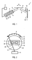
- FIG. 1 schematically shows the operating principle of a device 1 according to the invention for detecting an object 2 moved between a laser light source 4 and a wall 6.
- the laser light source 4 and a light receiver 5 are arranged opposite the wall 6, wherein light 9, which is illuminated by the laser light source 4, is first directed to a mirror device 8 and is projected by the mirror device 8 on the wall 6.
- the laser light source 4 is arranged at an angle to the mirror surface of the mirror device 8.
- the mirror device 8 comprises a movable, electronically controllable oscillating mirror, which can be pivoted in accordance with the direction of movement indicated by the arrow A.
- the mirror device 8 is coupled to an electronic control module, which in FIG. 1 not shown.
- the mirror device 8 may be, for example, a rotating faceted mirror or a pendulum mirror.
- the mirror device 8 projects a point-shaped laser beam 9 emitted by the laser light source 4 as a line onto a measuring field on the wall 6.
- the wall 6 is in FIG. 1 shown as a flat surface, however, according to the invention, as in FIG. 2 shown formed as a curved surface.
- the laser light source 4 facing surface of the wall 6 is at least partially reflective.
- the wall 6 has light areas 10 and dark areas 11 on the side facing the laser light source, forming a regular stripe pattern 12 in the example shown
- a light receiver 5 is arranged for the light 9 reflected by the wall 6.
- the light receiver 5 has the same orientation as the laser light source 4, so that it can receive light reflected from the wall 6, which falls on the mirror device 8, via the mirror device 8.
- the light receiver 5 is combined with the laser light source 4 in a scan module 15.
- the light receiver 5 has a light sensor which is coupled to an evaluation unit 13 for the received light signals.
- a contrast control unit 14 is provided with a threshold value switch for adjusting the contrast of the received light 9.
- the device 1 also has a time and temperature detection unit 17, which is coupled to the evaluation unit 13.
- time and temperature can also be detected with independent measuring devices for detecting the time or the temperature.
- the mirror device 8 projects the laser beam 9 in a line onto the wall 6, whereby the light line generated intersects the strip 12 provided on the wall 6 approximately at right angles. Due to the regular stripe pattern 12, light beams 9 are reflected by the wall 6 at regular intervals or are not reflected or diffusely reflected. In this way, the light sensor of the light receiver 5 receives light signals with higher and light signals with lower intensity or for certain area no light signal.
- the evaluation unit 13 the light signals of higher intensity as high level and light signals with lower intensity are recorded as low signals and combined in a high-low output signal 16.
- the high-low output signal 16 may be detected as a 0-1 bit pattern 23.
- An undisturbed 0-1 bit pattern 23 may be used as a reference pattern for comparison with a bit pattern having a spurious object 2.
- the contrast control unit 14 provided in the evaluation unit 13 can set the contrast of the light detected by the light sensor such that those signals which are above a certain threshold value are classified as high signals and the signals which are below this threshold value are low Signals are arranged.
- the contrast control unit 14 has a threshold value switch, with which an adjustment to the contrast ratios between the reference background on the wall 6 and a previously moved or placed object 2 can be made.
- the light signals detected by the light receiver 5 are changed, at least for a short time. Irregularities in the bit pattern 23 generated by the evaluation unit 13 are generated by the object 2, since the object 2, at least if it has opaque areas, prevents or reduces reflection of the bright areas 10 of the wall 6, so that the intensity of the bright Areas 10 of the wall 6 reflected light rays through the object 2 is reduced. Accordingly, at the point at which the object 2 has moved past the wall 6 or at which it is located, instead of high levels, which correspond to the bright areas 10 of the wall 6, at least briefly low level of the light receiver 5 are recorded.
- the stripe pattern 12 on the wall 6 is sufficiently dense and the strips and the spaces between them are correspondingly narrow, a plurality of bright areas 10 can be covered by the object 2, so that at the point at which the object 2 adjoins the wall 6 has passed or is placed on it, a series of low levels or 0's in the 0-1 bit pattern 23 is detected. From the number of low levels or the 0 values can then be deduced how large the object 2 is. In addition, it can be deduced from the position of the determined bit pattern interference on the position of the object 2.
- the apparatus and method described above may be used to detect moving and stationary objects between the laser light source 4 and the wall 6.
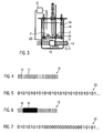
- FIG. 2 schematically shows the basis of FIG. 1 described functional principle of the device 1 according to the invention with reference to a specific embodiment of the invention in plan view and FIG. 3 shows this embodiment in side view.
- FIG. 2 and 3 shown embodiment of the invention are two objects to be measured 2, 3 in a translucent beaker 18 which is filled with a translucent liquid 19.
- the objects to be measured 2, 3 are here two steel balls, each resting on existing bitumen platelets 24 layers, which are held in a ring holder 22.
- a curved wall 6 is provided on one side of the vessel 18 below the ring holder, on which a vertical strip pattern 12 is shown.
- the wall 6 opposite is located on the other side of the beaker 18, a scanning module 15 with a laser light source 4, a mirror device 8 and a light receiver 5.
- a scanning module 15 with a laser light source 4, a mirror device 8 and a light receiver 5.
- mirror device 8 emanating from the laser light source 4 laser beam 9 is so on the Wall 6 projects on the wall 6 a laser light line intersecting the fringe pattern 12.
- the laser light reflected from the bright areas 10 of the wall is received by the light receiver 5 by means of the mirror device 8 in the scan module 15.
- the evaluation unit 13 of the scanning module 15 ie, without an object located between the scan module 15 and the wall 6, a regular 0-1 bit pattern 23 is formed, which corresponds to the regular strip of the strip pattern 12 on the wall 6.
- the balls 2, 3 reach the measuring range which is 25 ⁇ 0.4 mm below the ring holder 22, the balls 2, 3 are detected by the scanning module 15, the time and temperature detecting unit 17 determining the associated time t 2 or t 3 and the corresponding temperatures T 2 and T 3 detected.
- the evaluation unit 13 determines in the scan module 15, the size of the fallen object and can then determine whether it is actually one of the balls 2, 3 or if, for example, the size of the detected object rather indicates that the recognized object is a bubble rising in the vessel 18.
- the evaluation unit 13 has software which, depending on the used frequency of the laser light source 4, the type of the laser light source 4, the distance of the scanning module 15 and the wall 6 of the vessel 18, the composition of the liquid 19, the refractive index of the wall of the Vessel 18 and / or further constructive or trial-specific features processed the collected data.
- scan module 15 is a non-decoded scanning engine. That is, the scan engine 15 provides only a digitized signal of its scan logic, but does not translate the scanned pattern into a particular bar code set.
- the evaluation unit 13 of the scanning module 15 uses two digital signals, via which the time profile of a scan cycle and the read-in pattern can be determined, examples of such signals in the FIGS. 8 and 9 are shown.
- the scanning module 15 has as a background on the wall 6 a pattern with sharp light-dark transitions similar to that of a barcode, so that the functionality of the scanning module 15 is ensured.
- FIG. 4 schematically shows an example of the in FIG. 3 stripe pattern 12 used without interference object 2, 3.
- the stripe pattern 12 has alternating light and dark areas 10, 11, which are arranged at regular intervals.
- FIG. 5 shows a bit pattern 23 for the fringe pattern 12 FIG. 4 without interfering object 2, 3.
- a regular 0-1 bit pattern 23 results without disturbances, which can be used as a reference pattern.
- FIG. 6 shows an example of a stripe pattern 12 with an interfering object 2. At the point where the object 2 has moved past the stripe pattern or at which it was placed, no bright areas 10 can be seen.
- FIG. 7 shows a bit pattern 23, which the stripe pattern 12 with interfering object 2 from FIG. 6 equivalent. At the location where interference has occurred through the object 2, the bit pattern 23 has a series of 0 levels.
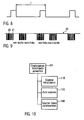
- FIG. 8 shows an example of a signal of an evaluation unit 13, with which the timing of the scan can be determined.
- the signal shown here delivers a high-low edge, wherein in the example shown here a measurement cycle has a duration T of approximately 33 milliseconds to approximately 39 milliseconds having.
- a scan cycle consists of a laser run from right to left and back again.
- FIG. 9 shows an example of an output signal 16 of an evaluation unit 13, wherein the signal shown outputs a read-in pattern.
- a low signal indicates a dark, less reflective tactile region and a high signal is assigned to a bright, highly reflective region.
- the background pattern shown on the wall 6 consists of black bars of a fixed width, which have a constant distance from each other. If there is no object 2, 3 between the scan module 15 and the bar pattern 12, a regular high-low output signal 16 is recorded on a dataout line of the scan module 15. If an object or an object 2, 3 introduced into the laser field of the scanning module 15, the bar pattern 12 is interrupted, resulting in a change of the dataout signal. Depending on the reflection properties of the object 2, 3, the signal at this point either an extended low or high signal. This pattern interruption is now detected and evaluated with the aid of the evaluation unit 13 provided evaluation.
- FIG. 10 schematically shows in a block diagram the steps to be coordinated by an I 2 C handler for the scan module 15.
- a received command is to be evaluated first.
- the scan module 15 is to be initialized.
- the scanning module 15 scans a line on the wall 6.
- the scanner data is returned to the evaluation unit 13.
- the scanned signals are read in by a PIC controller, the read-in samples are stored in a suitable form and offered to a host controller for further evaluation via an I 2 C bus interface.
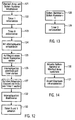
- FIG. 11 shows schematically by way of a block diagram how the scanner logic of the scan module 15 is initialized by means of a special I 2 C command.
- the scan module 15 is initially turned on in step 111 and a certain settling time of the laser mechanism is awaited.
- a timer "1" is initialized.
- the start of a new scan cycle is waited for.
- the timer "1" is started.
- step 115 the end of the scan cycle is waited for.
- step 116 the timer "1" is stopped and in step 117 the scan cycle time is determined and stored in the PIC controller.
- the scan module 15 remains turned on thereafter.
- FIG. 12 schematically shows by means of a block diagram the sub-steps executed in step 120 for the scanning of a line.
- the host controller sends a command for reading a scan line to the PIC controller, this starts with the pattern recognition routine.
- step 121 an overflow array and a bar number are initialized.
- step 122 the timer "1" is initialized.
- step 123 an internal timer, timer "0”, is initialized.
- the data-out signal of the scan module 15 is used as an interrupt source (INT), which is initialized in step 124.
- the system first waits until a new scan cycle begins. Thereafter, in step 126, the timer "0" and the interrupt source are activated.
- INT interrupt source
- step 127 the timer "1" is started, which delivers an interrupt after half of the scan cycle time. If this interrupt occurs, the read-in is ended, so that the read-in data only reproduce the pattern for one direction of the laser, for example from right to left.
- the timer "0" is set to trigger an overflow interrupt after a certain time, which is much smaller than the total cycle time.
- a counter containing a current bar number is now reset. If an INT interrupt, ie a high-low edge of the data-out signal, occurs, then the laser of the scan module 15 is at a new bar of the stripe pattern 12 FIG. 13 2, the current bar number in the associated interrupt routine is incremented in step 128 and the timer "0" is reset in step 129. It can thus be ensured that the overflow interrupt of the timer "0" does not occur in the case of a regular bar pattern 12. If the stripe pattern 12 is interrupted, however, the overflow occurs and a corresponding interrupt routine, as in FIG FIG.
- step 130 the current bar number is stored in an overflow array and in step 131 the number of overflows is incremented. If the overflow occurs several times with a bar number, the bar number is also stored multiple times in the array.
- the host controller can query the read-in data from the PIC controller and use it for further evaluation. It receives the contents of the overflow array, its size and the number of the last bar.
- step 132 of FIG. 12 the interrupt sources are deactivated and in step 133 the timers "0" and "1" are stopped.
- FIG. 15 schematically shows a further possible embodiment of the device 1 'according to the invention.
- the device 1 since the device 1 'includes elements similar to the device 1, the same reference numerals will be used for the same elements as in the device 1, referring to the above description of these elements.
- device 1 has a scanning module 15 arranged opposite an at least partially reflecting wall 6 with a laser light source 4 and a light receiver 5 and an evaluation unit 13. Between the scanning module 15 and the wall 6, a rotatable mirror device 8 is provided, with which laser light 9 can be projected onto the wall 6, wherein laser light reflected from the wall 6 is received by the light receiver 5.
- the wall 6 of the device 1 In contrast to the device 1, the wall 6 of the device 1 'has no striped pattern 12. However, the laser beams 9 emitted from the laser light source 4 are pulsed. When an object 2, 3 is moved between the laser light source 4 and the wall 6 or placed in the space between the laser light source 4 and the wall, the intensity of the light received by the light receiver 5 changes. The location at which the object 2, 3 was detected can be determined in the device 1 'using the applied frequency of the laser pulses. For example, a frequency of 10 kHz can be used for this purpose.
- the device 1 ' Even with the device 1 ', it is possible to detect not only the object 2, 3 itself but also using a time and temperature detection unit 17, the time and the temperature at which the object was detected. In this way, a complete movement sequence of an object can be reconstructed. However, the device 1 'can also be used to detect a stationary object 2, 3.
- the size of the detected object can be determined on the basis of the intensity changes determined per scanned point.
- the sampling frequency necessary for the application results from the distance of the laser to the measurement object 2, 3 and its size.
- the sampling frequency it is necessary that the sampling frequency be selected such that the distance traveled during a cycle including a pulse duration and a pause is less than half of the object size.
- the sampling frequency must be selected such that the distance traveled during a cycle is less than half the required measurement accuracy.
Abstract
Description
Die vorliegende Erfindung betrifft eine Vorrichtung und ein Verfahren zum Erkennen von Objekten mit einer Lichtquelle und einem Lichtempfänger.The present invention relates to an apparatus and a method for detecting objects with a light source and a light receiver.
Eine Vorrichtung dieser Art wird beispielsweise benötigt, um in dem in der europäischen Norm EN 1427 beschriebenen Ring- und Kugel-Verfahren den Erweichungspunkt eines zu testenden Bitumens oder bitumenhaltigen Bindemittels zu bestimmen. Hierbei werden in einem mit einer Flüssigkeit gefüllten lichtdurchlässigen Gefäß auf einer Ringhalterung, auf Bitumenschichtplättchen liegende Stahlkugeln vorgesehen, welche beim kontrollierten Erwärmen der Flüssigkeit im Testverlauf, umhüllt von erweichtem Bitumenmaterial, nach unten fallen und in einem Abstand von 25,0 ± 0,4 mm unterhalb der Ringhalterung detektiert werden. Um die herabfallenden Kugeln an der Messstelle detektieren zu können, werden beispielsweise aus einer LED und einem Lichtempfänger bestehende, am Gefäßrand angeordnete Lichtschranken verwendet. Dieses Prinzip besitzt den Nachteil, dass Störeinflüsse in der Flüssigkeit, wie beispielsweise durch die Erwärmung in dem Gefäß aufsteigende Bläschen oder eine viskositätsabhängige Schichtung in diversen Prüfmedien von der Lichtschranke als Kugel fehlinterpretiert werden können und somit zu unzuverlässigen Ergebnissen führen können.A device of this kind is required, for example, to determine the softening point of a bitumen or bituminous binder to be tested in the ring and ball method described in the European standard EN 1427. In this case, provided in a liquid-filled translucent vessel on a ring holder, lying on bitumen layer steel balls, which fall during the controlled heating of the liquid in the course of the test, covered by softened bitumen material, fall down and at a distance of 25.0 ± 0.4 mm be detected below the ring holder. In order to detect the falling balls at the measuring point, for example, consisting of an LED and a light receiver, arranged on the vessel edge photocells are used. This principle has the disadvantage that disturbing influences in the liquid, such as bubbles rising due to heating in the vessel or a viscosity-dependent stratification in various test media, can be misinterpreted by the light barrier as a sphere and thus lead to unreliable results.
Die Druckschrift
Die Druckschrift
Die Druckschrift
Die Druckschrift
Es ist daher die Aufgabe der vorliegenden Erfindung, eine zuverlässige und dennoch leicht anwendbare Vorrichtung und ein entsprechendes Verfahren zum Erkennen von Objekten, wie den oben beschriebenen herabfallenden Kugeln, zur Verfügung zu stellen.It is therefore the object of the present invention to provide a reliable yet easily applicable device and a corresponding method for detecting objects, such as the falling balls described above.
Diese Aufgabe wird durch eine Vorrichtung zum Erkennen von Objekten mit einer Lichtquelle und einem Lichtempfänger gelöst, bei welcher das Objekt in einer in einem lichtdurchlässigen Gefäß vorgesehenen Flüssigkeit nach unten fallbar angeordnet ist, wobei die Lichtquelle eine Laserlichtquelle ist, die Vorrichtung eine wenigstens teilweise reflektierende Wand aufweist und zwischen der Laserlichtquelle und der Wand ein Zwischenraum vorgesehen ist, durch den ein Objekt bewegbar oder in dem ein Objekt platzierbar ist, und im Strahlengang zwischen der Laserlichtquelle und der Wand eine bewegbare Spiegeleinrichtung derart angeordnet ist, dass von der Laserlichtquelle abgestrahltes Licht auf die Wand richtbar ist, wobei die Bewegung der Spiegeleinrichtung so steuerbar ist, dass die Wand wenigstens entlang einer Linie mit dem von der Laserlichtquelle abgestrahlten Licht bestrahlbar ist und von der Wand reflektiertes Licht von dem Lichtempfänger detektierbar ist, und wobei die Wand gewölbt ist, wobei die Wand alternierende helle und dunkle Bereiche, die ein regelmäßiges Streifenmuster ausbilden, aufweist oder das Licht gepulst istThis object is achieved by a device for detecting objects with a light source and a light receiver, in which the object is disposed downwardly in a liquid provided in a transparent vessel, wherein the light source is a laser light source, the device is an at least partially reflecting wall and between the laser light source and the wall, a gap is provided, through which an object is movable or in which an object can be placed, and in the beam path between the laser light source and the wall, a movable mirror device is arranged such that emitted by the laser light source light on the Wall is directable, wherein the movement of the mirror device is controllable so that the wall is at least along a line with the light emitted from the laser light source can be irradiated and light reflected from the wall of the light receiver is detectable, and wherein the wall arched bt, the wall having alternating bright and dark areas forming a regular stripe pattern, or the light being pulsed
Mit der erfindungsgemäßen Vorrichtung ist es möglich, eine Änderung der Intensität der von der Wand reflektierten Lichtstrahlung als Indiz zum Erkennen eines zwischen der La-serlichtquelle und der Wand vorhandenen Objektes zu verwenden. Da der von der Laserlichtquelle ausgehende Lichtstrahl eine ganze Linie auf der Wand abtasten kann, können bei entsprechender Abtastfrequenz und Auflösung der vom Lichtempfänger detektierten, reflektierten Lichtstrahlung nicht nur das Objekt selbst sondern auch dessen bei der Messung ermittelte Position auf der Projektionslinie der Laserlichtquelle sowie die Größe des Objektes erfasst werden. Somit kann eine sichere Erkennung bewegter als auch ruhender Objekte mit einer relativ einfachen Anordnung gewährleistet werden.With the device according to the invention, it is possible to change the intensity of the light radiation reflected by the wall as an indication for detecting a between the laser light source and the wall of existing object to use. Since the light beam emanating from the laser light source can scan a whole line on the wall, not only the object itself but also its position determined on the projection line of the laser light source as well as the size can be scanned with an appropriate scanning frequency and resolution of the light reflected by the light receiver of the object are detected. Thus, a secure detection of moving and stationary objects can be ensured with a relatively simple arrangement.
Es ist ganz besonders von Vorteil, wenn die Wand alternierende helle und dunkle Bereiche aufweist. Mit Hilfe der hellen und dunklen Bereiche auf der Wand können Markierungen gesetzt werden, anhand welcher eine genaue Ermittlung der Größe und der Position des Objektes möglich ist. Bewegt sich beispielsweise ein lichtundurchlässiges Objekt an den hellen und dunklen Bereichen der Wand vorbei oder wird es vor diesem Bereich platziert, werden diese zumindest kurzzeitig abgedeckt, so dass der Lichtempfänger zu diesem Zeitpunkt insbesondere von den hellen Bereichen keine oder eine durch den Störeinfluss verringerte reflektierte Lichtstrahlung aufnehmen kann. Wird beispielsweise von dem Lichtempfänger ein heller Bereich als High-Pegel und ein dunkler Bereich als Low-Pegel erfasst, tritt beim Vorbeibewegen oder Platzieren eines Objektes an einem hellen Bereich beim Lichtempfänger eine Signaländerung auf, bei welcher anstatt eines High-Pegels für die entsprechenden hellen Bereiche der Wand ein Low-Pegel erfasst wird. Auf diese Weise kann die Position des Objektes anhand der Position der durch das Objekt abgedeckten hellen Bereiche festgelegt werden, wobei aus der Anzahl der abgedeckten hellen Bereiche auf die Größe des Objektes geschlossen werden kann.It is especially beneficial if the wall has alternating light and dark areas. With the help of the light and dark areas on the wall markings can be set, on the basis of which an exact determination of the size and the position of the object is possible. If, for example, an opaque object moves past the light and dark areas of the wall or is placed in front of this area, they are at least temporarily covered, so that the light receiver at this time, in particular of the bright areas no reflected or reduced by the interference reflected light radiation can record. If, for example, the light receiver detects a bright area as a high level and a dark area as a low level, a signal change occurs when the object moves past or places in a bright area near the light receiver, instead of a high level for the corresponding bright areas Areas of the wall a low level is detected. In this way, the position of the object can be determined based on the position of the bright areas covered by the object, wherein the size of the object can be deduced from the number of bright areas covered.
Es hat sich als besonders günstig erwiesen, wenn die hellen und dunklen Bereiche der Wand ein regelmäßiges Streifenmuster ausbilden. Ein solches Streifen- oder Balkenmuster kann bei dem Lichtempfänger beispielsweise als regelmäßiges 0-1-Bitmuster erfasst werden. Bewegt sich ein Objekt an dem Streifenmuster vorbei oder wird es vor dem Streifenmuster platziert, tritt in dem Bitmuster eine Störung auf, welche sich beispielsweise durch eine Änderung von High-Pegeln in Low-Pegel bemerkbar macht. Dabei kann die Dichte und die Breite der Streifen an die Größe der zu erfassenden Objekte angepasst werden, so dass eine möglichst genaue Identifizierung der jeweiligen Objektgröße möglich ist.It has proved to be particularly favorable when the light and dark areas of the wall form a regular striped pattern. Such a stripe or bar pattern may be detected in the photoreceiver, for example, as a regular 0-1 bit pattern. If an object moves past the stripe pattern or if it is placed in front of the stripe pattern, a disturbance occurs in the bit pattern, which manifests itself, for example, as a change from high levels to low levels. In this case, the density and the width of the strips can be adapted to the size of the objects to be detected, so that the most accurate possible identification of the respective object size is possible.
Entsprechend einer weiteren vorteilhaften Variante der Erfindung ist das von der Laserlichtquelle abgestrahlte Licht gepulst. Bei dieser Anordnung können Laserimpulse mit bestimmten Frequenzen verwendet werden, um eine Linie auf der Wand abzurastern, wobei zur Auflösung der zwischen der Laserlichtquelle und der Wand bewegten oder platzierten Objekte die Frequenz der eingesetzten Laserimpulse verwendet werden kann. Somit ist es bei dieser Anordnung für die Objekterkennung nicht unbedingt notwendig, dass die Wand helle und dunkle Bereiche aufweist.According to a further advantageous variant of the invention, the light emitted by the laser light source is pulsed. In this arrangement, laser pulses with certain frequencies can be used to scan a line on the wall, wherein the Resolution of between the laser light source and the wall moved or placed objects the frequency of the laser pulses used can be used. Thus, in this arrangement for object recognition, it is not essential that the wall has bright and dark areas.
Gemäß einem günstigen Beispiel der Erfindung weist die Spiegeleinrichtung einen elektronisch steuerbaren Schwingspiegel auf. Beispielsweise können rotierende facettierte Spiegel oder auch pendelnde Spiegel eingesetzt werden. Durch die Bewegbarkeit eines solchen Spiegels können punktförmige Laserstrahlen einfach als Linie auf ein Messfeld an der Wand projiziert werden. Vorzugsweise ist während einer Messung die Bewegungsgeschwindigkeit der Spiegeleinrichtung als konstanter Wert eingestellt.According to a favorable example of the invention, the mirror device has an electronically controllable oscillating mirror. For example, rotating faceted mirrors or oscillating mirrors can be used. Due to the mobility of such a mirror, punctiform laser beams can simply be projected as a line onto a measuring field on the wall. Preferably, the movement speed of the mirror device is set as a constant value during a measurement.
Gemäß einer vorteilhaften Ausführungsform der Erfindung weist der Lichtempfänger einen Lichtsensor auf, der mit einer Auswerteeinheit gekoppelt ist. Die Auswerteeinheit kann beispielsweise von dem Lichtsensor ermittelte Werte in High-Pegel für Hell-Bereiche und Low-Pegel für Dunkel-Bereiche umwandeln, welche Daten mit einem Referenzmuster verglichen werden können, um ein zwischen der Laserlichtquelle und der Wand bewegtes oder platziertes Objekt zu erkennen.According to an advantageous embodiment of the invention, the light receiver has a light sensor which is coupled to an evaluation unit. The evaluation unit can, for example, convert values determined by the light sensor into high levels for light areas and low levels for dark areas, which data can be compared with a reference pattern in order to detect an object moved or placed between the laser light source and the wall ,
Vorzugsweise weist die Auswerteeinheit eine Kontrastregelungseinheit auf. Hiermit kann eingestellt werden, welche Intensität der von dem Lichtempfänger empfangenen Lichtstrahlung als heller Bereich oder als dunkler Bereich einzuordnen ist. So ist es beispielsweise möglich, dass ein reflektierender Bereich der Wand durch ein davortretendes Objekt lediglich diffus Licht reflektiert, so dass zwar reflektierte Lichtstrahlung aus diesem Bereich von dem Lichtempfänger empfangen wird, aber das empfangene Signal eine geringe Intensität aufweist. In solchen Fällen kann mit Hilfe der Kontrastregelungseinheit der Kontrast so eingestellt werden, dass Signale mit geschwächter Intensität als Low-Pegel eingeordnet werden.Preferably, the evaluation unit has a contrast control unit. Hereby can be adjusted, which intensity of the light radiation received by the light receiver is to be classified as a bright area or as a dark area. It is thus possible, for example, for a reflecting region of the wall to only diffusely reflect light through a preceding object, so that, although reflected light radiation from this region is received by the light receiver, the received signal has a low intensity. In such cases, the contrast can be adjusted by means of the contrast control unit so that signals with reduced intensity are classified as low level.
Gemäß einer bevorzugten Ausführungsvariante der vorliegenden Erfindung sind die Laserlichtquelle und der Lichtempfänger in einem Scanmodul mit einem uncodierten High-Low-Ausgangssignal zusammengefasst. Somit können die Laserlichtquelle und der Lichtempfänger praktikabel in einem Gerät untergebracht werden, wodurch die Messvorrichtung für einen Anwender vereinfacht wird. Auch kann auf diese Weise die Ausrichtung der Laserlichtquelle zu dem Lichtempfänger genau und fest aufeinander abgestimmt werden. Das uncodierte Ausgangssignal ermöglicht es zudem auf einfache Weise, Objekte im Erfassungsbereich des Scanmoduls zu detektieren.According to a preferred embodiment of the present invention, the laser light source and the light receiver are combined in a scan module with an uncoded high-low output signal. Thus, the laser light source and the light receiver can be practically accommodated in one apparatus, thereby simplifying the measuring apparatus for a user. Also, in this way, the alignment of the laser light source to the light receiver can be precisely and firmly matched. The uncoded output signal also makes it possible in a simple manner to detect objects in the detection range of the scanning module.
Vorteilhafterweise weist die Vorrichtung eine Zeit- und/oder Temperaturerfassungseinheit auf. Somit kann die Zeit und/oder die Temperatur, bei welcher das Objekt von der erfindungsgemäßen Vorrichtung erfasst wurde, ermittelt werden, wobei die Objekterkennung mit der Zeit- und/oder Temperaturerkennung logisch verknüpft werden kann.Advantageously, the device has a time and / or temperature detection unit. Thus, the time and / or the temperature at which the object was detected by the device according to the invention, can be determined, wherein the object recognition can be logically linked to the time and / or temperature detection.
In einer speziellen Ausgestaltung der vorliegenden Erfindung ist das bewegte Objekt eine Kugel, welche in einer in einem lichtdurchlässigen Gefäß vorgesehenen Flüssigkeit nach unten fallbar angeordnet ist, wobei um das Gefäß die Laserlichtquelle, der Lichtempfänger, die Spiegeleinrichtung und die Wand angeordnet sind. Eine solche Anordnung kann verwendet werden, um anhand des Zeitpunktes, an dem die Kugel erfasst wird, Rückschlüsse darauf zu ziehen, zu welchem Zeitpunkt der Fall der Kugel eingesetzt hat. Ebenso kann diese Vorrichtung verwendet werden, um eine Bewegungsgeschwindigkeit einer Kugel in einer Flüssigkeit zu ermitteln.In a special embodiment of the present invention, the moving object is a ball, which is arranged downwardly fallable in a liquid provided in a light-transmitting vessel, wherein the laser light source, the light receiver, the mirror device and the wall are arranged around the vessel. Such an arrangement can be used to draw conclusions on the time at which the ball is detected, at which time the fall of the ball has begun. Likewise, this device can be used to determine a speed of movement of a ball in a liquid.
Gemäß einer besonders bevorzugten Ausführungsform der Erfindung wird die Kugel auf einer erweichbaren Schicht in einer Ringhalterung gehalten, unter welcher im Abstand von 25,0 ± 0,4 mm ein Messbereich zum Erfassen der Kugel vorgesehen ist. Diese Anordnung eignet sich insbesondere für die Verwendung der Vorrichtung in dem so genannten Ring- und Kugel-Verfahren, in welchem der Erweichungspunkt von Bitumen- oder bitumenhaltigem Bindemittelschichten bestimmt wird. So könnte beispielsweise eine Anordnung verwendet werden, welche in der europäischen Norm EN 1427:1999 beschrieben ist.According to a particularly preferred embodiment of the invention, the ball is held on a softenable layer in a ring holder, under which a measuring range for detecting the ball is provided at a distance of 25.0 ± 0.4 mm. This arrangement is particularly suitable for the use of the device in the so-called ring and ball method in which the softening point of bitumen or bituminous binder layers is determined. For example, an arrangement could be used which is described in the European standard EN 1427: 1999.
Die Aufgabe der Erfindung wird ferner durch ein Verfahren zum Erkennen bewegter Objekte mit einer Lichtquelle und einem Lichtempfänger gelöst, bei welchem ein in einer in einem lichtdurchlässigen Gefäß vorgesehenen Flüssigkeit herabfallendes Objekt erfasst wird, wobei die Lichtquelle eine Laserlichtquelle ist, von welcher Licht auf eine bewegbare Spiegeleinrichtung gerichtet wird, wobei die Spiegeleinrichtung das Licht auf eine gewölbte, zumindest teilweise reflektierende Wand richtet und die Spiegeleinrichtung dabei so gesteuert wird, dass die Wand wenigstens entlang einer Linie durch das Licht bestrahlt wird, und wobei der Lichtempfänger das von der Wand reflektierte Licht detektiert und dabei ein sich zwischen der Laserlichtquelle und der Wand bewegendes oder platziertes Objekt durch eine Änderung des detektierten, reflektierten Lichts erfasst, und wobei ein auf der Wand vorgesehenes, regelmäßiges Streifenmuster von dem Lichtempfänger mit einer Auswerteeinheit als kontinuierliches, uncodiertes 0-1-Bitmuster erfasst wird oder das Licht gepulst auf die Spiegeleinrichtung gestrahlt wird.The object of the invention is further achieved by a method for detecting moving objects with a light source and a light receiver, in which an object falling in a liquid provided in a translucent vessel is detected, the light source being a laser light source, from which light onto a movable Mirror device is directed, wherein the mirror device directs the light on a curved, at least partially reflecting wall and the mirror device is controlled so that the wall is irradiated along at least one line through the light, and wherein the light receiver detects the reflected light from the wall and thereby an object moving or placed between the laser light source and the wall is detected by a change in the detected reflected light, and wherein a regular striped pattern provided on the wall is received by the light receiver with an evaluation unit as contine is detected, or the light is pulsed pulsed on the mirror device.
Mit dem erfindungsgemäßen Verfahren können Objekte zwischen der Laserlichtquelle und der Wand entlang der gesamten von dem Laserlicht erfassten Linie erkannt werden, wobei die Lichtquelle und der Lichtempfänger auf der gleichen Seite der Vorrichtung, gegenüber der Wand, angeordnet werden können, was es möglich macht, die Lichtquelle und den Lichtempfänger in einem Scanmodul zu integrieren. Mit Hilfe dieses Verfahrens können somit Objekte auf einfache Weise sicher erfasst werden.With the method according to the invention, objects between the laser light source and the wall can be detected along the entire line detected by the laser light, whereby the light source and the light receiver can be arranged on the same side of the device, opposite to the wall, which makes it possible Light source and the Integrate light receiver in a scan module. With the help of this method thus objects can be detected easily in a simple manner.
Gemäß einer bevorzugten Ausführungsform der Erfindung ist der Lichtempfänger mit einer Auswerteeinheit gekoppelt, welche in einem Ausgangssignal für helle Bereiche der Wand einen High-Pegel und für dunkle Bereiche der Wand einen Low-Pegel ausgibt Somit können helle und dunkle Bereich der Wand genutzt werden, um anhand von Intensitätsänderungen des von dem Lichtempfänger empfangenen, reflektierten Laserlichts an der Wand vorbei bewegte oder dort platzierte Objekte zu erkennen.According to a preferred embodiment of the invention, the light receiver is coupled to an evaluation unit, which outputs a high level in an output signal for light areas of the wall and a low level for dark areas of the wall. Thus, light and dark areas of the wall can be used to to be detected on the wall by moving past or there objects placed on the wall by means of intensity changes of the light receiver received by the reflected laser light.
Hierbei ist es besonders günstig, wenn ein auf der Wand vorgesehenes, regelmäßiges Streifenmuster von dem Lichtempfänger mit der Auswerteeinheit als kontinuierliches, uncodiertes 0-1-Bitmuster erfasst wird. Dabei bildet das uncodierte 0-1-Bitmuster ohne ein sich zwischen der Lichtquelle und der Wand befindliches Störobjekt ein geeignetes Referenzmuster aus, das es ermöglicht, bei dessen Störung durch ein Objekt nicht nur das Objekt selbst sondern auch dessen Größe zu erfassen.It is particularly advantageous if a regular strip pattern provided on the wall is detected by the light receiver with the evaluation unit as a continuous, uncoded 0-1-bit pattern. In this case, the uncoded 0-1-bit pattern without a fault object located between the light source and the wall forms a suitable reference pattern, which makes it possible to detect not only the object itself but also its size when it is disturbed by an object.
Es ist besonders von Vorteil, wenn das Ausgangssignal durch das Objekt so gestört wird, dass in dem Bereich, in dem sich das Objekt bewegt oder platziert ist, anstelle von High-Pegeln Low-Pegel erfasst werden. Hierdurch ist auf einfache, aber eindeutige Weise eine genaue Aussage dahingehend möglich, ob sich ein Objekt zwischen der Lichtquelle und der Wand befindet oder nicht.It is particularly advantageous if the output signal is disturbed by the object so that in the area in which the object is moved or placed, low levels are detected instead of high levels. This makes it possible in a simple but unambiguous way to determine whether an object is located between the light source and the wall or not.
Gemäß einer weiteren, ebenfalls sehr vorteilhaften Ausführungsform der Erfindung wird das Licht von der Laserlichtquelle gepulst auf die Spiegeleinrichtung gestrahlt. Damit kann das Laserlicht von der Spiegeleinrichtung gepulst auf die Wand projiziert werden und das von der Wand reflektierte Licht in entsprechenden Impulsen von dem Lichtempfänger erfasst werden, wobei anhand der verwendeten Frequenz genau ermittelt werden kann, zu welchem Zeitpunkt und an welcher Stelle das Objekt zwischen der Laserlichtquelle und der Wand detektiert wurde.According to a further, likewise very advantageous embodiment of the invention, the light is pulsed by the laser light source pulsed on the mirror device. Thus, the laser light from the mirror device can be projected in a pulsed manner onto the wall and the light reflected from the wall can be detected in corresponding pulses by the light receiver, it being possible to determine exactly at what time and at which point the object between the light source and the frequency used Laser light source and the wall was detected.
In einem speziellen Beispiel der Erfindung wird eine in einer Flüssigkeit in einem lichtdurchlässigen Gefäß herabfallende Kugel erfasst. Mit diesem Verfahren kann anhand des Erfassungszeitpunktes der Kugel auf die Zeit des Beginns ihres Falls in dem Gefäß geschlossen werden. Es ist auch möglich, mit diesem Verfahren die Bewegungsgeschwindigkeit der Kugel in der Flüssigkeit zu ermitteln.In a specific example of the invention, a ball falling in a liquid in a translucent vessel is detected. With this method, based on the detection time of the ball can be closed to the time of the beginning of their fall in the vessel. It is also possible with this method to determine the speed of movement of the ball in the liquid.
Gemäß einem besonders bevorzugten Beispiel der Erfindung ist die Kugel eine Stahlkugel, die vor dem Herabfallen auf einer Schicht in einer Ringanordnung aufliegt, wobei die Schicht bei einer bestimmten Temperatur erweicht wird und die vom Schichtmaterial umhüllte Kugel nach unten fällt, wobei die Kugel nach einer bestimmten Fallstrecke erfasst wird. Dieses Verfahren eignet sich besonders gut bei der Verwendung in dem so genannten Ring- und Kugel-Verfahren zur Bestimmung des Erweichungspunktes von Bitumen oder bitumenhaltigen Bindemitteln, welches beispielsweise in der europäischen Norm EN 1427:1999 beschrieben ist, auf welche hier Bezug genommen wird.According to a particularly preferred example of the invention, the ball is a steel ball which rests against a layer in a ring arrangement before falling down, wherein the layer is softened at a certain temperature and the ball covered by the layer material falls downwards, the ball after a certain Fall range is detected. This method is particularly suitable for use in the so-called ring and ball method for determining the softening point of bitumen or bituminous binders, which is described for example in the European standard EN 1427: 1999, which is incorporated herein by reference.
Eigenschaften, die Funktionsweise und Vorteile der vorliegenden Erfindung werden im folgenden anhand der Figuren der Zeichnung beschrieben, in welchen
Figur 1- schematisch das Funktionsprinzip einer ersten Ausführungsform der vorliegenden Erfindung zeigt;
Figur 2- schematisch das Funktionsprinzip der
Vorrichtung von Figur 1 anhand einer Ring-Kugel-Messanordnung in der Draufsicht zeigt; Figur 3- schematisch die
Anordnung aus Figur 2 in der Seitenansicht zeigt; Figur 4- schematisch ein Streifenmuster ohne Störobjekt zeigt;
Figur 5- ein Bitmuster ohne Störobjekt entsprechend dem
Streifenmuster aus Figur 4 zeigt; Figur 6- schematisch ein Streifenmuster mit Störobjekt zeigt;
- Figur 7
- ein Bitmuster mit Störobjekt entsprechend dem
Streifenmuster aus Figur 6 zeigt; Figur 8- ein Beispiel für ein Signal eines Scanmoduls zeigt, mit welchem der zeitliche Verlauf des Scanvorgangs bestimmt wird;
Figur 9- ein Beispiel für eine Ausgangssignal mit High- und Low-Pegeln eines Scanmoduls zeigt;
Figur 10- ein Blockdiagramm zeigt, das die I2C-Handler-Funktion darstellt;
Figur 11- die für eine Initialisierung des Scanmoduls erforderlichen Schritte anhand eines Blockdiagramms zeigt;
Figur 12- die zum Scannen einer Zeile erforderlichen Schritte anhand eines Blockdiagramms zeigt;
Figur 13- die Schritte eines INT-Interrupts beim Erkennen eines nächsten Balkens in einem Blockdiagramm zeigt;
Figur 14- in einem Blockdiagramm die Schritte eines Timer "0"-Überlaufinterrupts zeigt; und
Figur 15- schematisch das Funktionsprinzip einer weiteren Ausführungsform der vorliegenden Erfindung zeigt
- FIG. 1
- schematically shows the operating principle of a first embodiment of the present invention;
- FIG. 2
- schematically the operating principle of the device of
FIG. 1 using a ring-ball measuring arrangement in plan view shows; - FIG. 3
- schematically the arrangement
FIG. 2 in the side view shows; - FIG. 4
- schematically shows a stripe pattern without interfering object;
- FIG. 5
- a bit pattern without a disturbance object corresponding to the stripe pattern
FIG. 4 shows; - FIG. 6
- schematically shows a stripe pattern with interfering object;
- FIG. 7
- a bit pattern with a disturbing object corresponding to the stripe pattern
FIG. 6 shows; - FIG. 8
- shows an example of a signal of a scan module, with which the timing of the scan is determined;
- FIG. 9
- shows an example of an output signal with high and low levels of a scan module;
- FIG. 10
- shows a block diagram illustrating the I 2 C handler function;
- FIG. 11
- shows the steps required to initialize the scan module based on a block diagram;
- FIG. 12
- the steps required to scan a line are shown in block diagram form;
- FIG. 13
- shows the steps of an INT interrupt upon detection of a next bar in a block diagram;
- FIG. 14
- in a block diagram shows the steps of a timer "0" overflow interrupt; and
- FIG. 15
- schematically shows the principle of operation of another embodiment of the present invention
In der Vorrichtung 1 ist die Laserlichtquelle 4 und ein Lichtempfänger 5 gegenüber der Wand 6 angeordnet, wobei Licht 9, das von der Laserlichtquelle 4 angestrahlt wird, zunächst auf eine Spiegeleinrichtung 8 gerichtet wird und von der Spiegeleinrichtung 8 auf die Wand 6 projiziert wird. Hierfür ist die Laserlichtquelle 4 im Winkel zu der Spiegelfläche der Spiegeleinrichtung 8 angeordnet.In the
Die Spiegeleinrichtung 8 umfasst einen bewegbaren, elektronisch steuerbaren Schwingspiegel, welcher entsprechend der durch den Pfeil A angedeuteten Bewegungsrichtungen schwenkbar ist. Die Spiegeleinrichtung 8 ist mit einem elektronischen Steuermodul gekoppelt, welches in
Die Spiegeleinrichtung 8 projiziert einen von der Laserlichtquelle 4 abgestrahlten punktförmigen Laserstrahl 9 durch ihre Bewegung als Linie auf ein Messfeld auf der Wand 6.The
Die Wand 6 ist in
Gegenüber der Wand 6 ist ein Lichtempfänger 5 für das von der Wand 6 reflektierte Licht 9 angeordnet. Der Lichtempfänger 5 weist die gleiche Ausrichtung wie die Laserlichtquelle 4 auf, so dass er von der Wand 6 reflektiertes Licht 9, das auf die Spiegeleinrichtung 8 fällt, über die Spiegeleinrichtung 8 empfangen kann. Der Lichtempfänger 5 ist mit der Laserlichtquelle 4 in einem Scanmodul 15 zusammengefasst.Opposite the
Der Lichtempfänger 5 weist einen Lichtsensor auf, der mit einer Auswerteeinheit 13 für die empfangenen Lichtsignale gekoppelt ist. In der Auswerteeinheit 13 ist eine Kontrastregelungseinheit 14 mit einem Schwellwertschalter zum Einstellen des Kontrastes des empfangenen Lichtes 9 vorgesehen.The
Die Vorrichtung 1 weist zudem eine Zeit- und Temperaturerfassungseinheit 17 auf, welche mit der Auswerteeinheit 13 gekoppelt ist. In andren, nicht gezeigten Ausführungsformen der Erfindung können Zeit und Temperatur auch mit voneinander unabhängigen Messeinrichtungen zum Erfassen der Zeit oder der Temperatur erfasst werden.The
Wird von der Laserlichtquelle 4 Laserlicht 9 auf die Spiegeleinrichtung 8 gestrahlt, projiziert die Spiegeleinrichtung 8 den Laserstrahl 9 durch ihre Bewegung in einer Linie auf die Wand 6, wobei die dabei erzeugte Lichtlinie die auf der Wand 6 vorgesehenen Streifen 12 etwa im rechten Winkel schneidet. Durch das regelmäßige Streifenmuster 12 werden durch die Wand 6 in regelmäßigen Abständen Lichtstrahlen 9 reflektiert bzw. nicht oder diffus reflektiert. Auf diese Weise empfängt der Lichtsensor des Lichtempfängers 5 Lichtsignale mit höherer und Lichtsignale mit geringerer Intensität oder für bestimmte Bereich gar kein Lichtsignal.If the
Durch die Auswerteeinheit 13 werden die Lichtsignale höherer Intensität als High-Pegel und Lichtsignale mit geringerer Intensität als Low-Signale aufgenommen und in einem High-Low-Ausgangssignal 16 zusammengefasst. Das High-Low-Ausgangssignal 16 kann als ein 0-1-Bitmuster 23 erfasst werden. Ein ungestörtes 0-1-Bitmuster 23 kann als Referenzmuster für einen Vergleich mit einem Bitmuster mit einem Störobjekt 2 verwendet werden.By the
Die in der Auswerteeinheit 13 vorgesehene Kontrastregelungseinheit 14 kann den Kontrast des von dem Lichtsensor erfassten Lichtes so einstellen, dass diejenigen Signale, die über einem bestimmten Schwellwert liegen, als High-Signale eingeordnet werden, und die Signale, die unter diesem Schwellwert liegen, als Low-Signale eingeordnet werden. Hierfür weist die Kontrastregelungseinheit 14 einen Schwellwertschalter auf, mit welchem eine Anpassung an die Kontrastverhältnisse zwischen dem Referenzhintergrund auf der Wand 6 und einem davor bewegten oder platzierten Objekt 2 vorgenommen werden kann.The
Bewegt sich ein Objekt 2 in einem Zwischenraum zwischen der Laserlichtquelle 4 und der Wand 6 an der durch die Spiegeleinrichtung 8 auf die Wand 6 projizierten Linie vorbei oder wird es dort platziert, werden zumindest kurzzeitig die von dem Lichtempfänger 5 erfassten Lichtsignale verändert. Durch das Objekt 2 werden Unregelmäßigkeiten in dem von der Auswerteeinheit 13 erzeugten Bitmuster 23 erzeugt, da das Objekt 2, zumindest wenn es lichtundurchlässige Bereiche besitzt, eine Reflexion der hellen Bereiche 10 der Wand 6 verhindert oder verringert, so dass die Intensität der von den hellen Bereichen 10 der Wand 6 reflektierten Lichtstrahlen durch das Objekt 2 verringert wird. Entsprechend werden an der Stelle, an welcher sich das Objekt 2 an der Wand 6 vorbeibewegt hat bzw. an welcher es sich befindet, anstelle von High-Pegeln, welche den hellen Bereichen 10 der Wand 6 entsprechen, zumindest kurzzeitig Low-Pegel von dem Lichtempfänger 5 erfasst werden.If an
Ist das Streifenmuster 12 auf der Wand 6 ausreichend dicht und sind die Streifen und die dazwischen befindlichen Abstände entsprechend schmal, können durch das Objekt 2 mehrere helle Bereiche 10 abgedeckt werden, so dass an der Stelle, an der das Objekt 2 sich an der Wand 6 vorbeibewegt hat oder an der es platziert ist, eine Reihe von Low-Pegeln bzw. 0-Werten in dem 0-1-Bitmuster 23 ermittelt wird. Aus der Anzahl der Low-Pegel bzw. der 0-Werte ist dann ableitbar, wie groß das Objekt 2 ist. Zudem kann von der Position der ermittelten Bitmusterstörung auf die Position des Objektes 2 geschlossen werden.If the
Die oben beschriebene Vorrichtung und das Verfahren können zum Erfassen bewegter und ruhender Objekte zwischen der Laserlichtquelle 4 und der Wand 6 verwendet werden.The apparatus and method described above may be used to detect moving and stationary objects between the
In der in
Um das Becherglas 18 ist auf einer Seite des Gefäßes 18 unterhalb der Ringhalterung eine gewölbte Wand 6 vorgesehen, auf welcher ein senkrechtes Streifenmuster 12 abgebildet ist.To the
Der Wand 6 gegenüber befindet sich auf der anderen Seite des Becherglases 18 ein Scanmodul 15 mit einer Laserlichtquelle 4, einer Spiegeleinrichtung 8 und einem Lichtempfänger 5. Durch die in dem Scanmodul 15 vorgesehene Spiegeleinrichtung 8 wird ein von der Laserlichtquelle 4 ausgehender Laserstrahl 9 so auf die Wand 6 projiziert, dass sich auf der Wand 6 eine das Streifenmuster 12 schneidende Laserlichtlinie ergibt.The
Das von den hellen Bereichen 10 der Wand reflektierte Laserlicht wird durch den Lichtempfänger 5 mittels der Spiegeleinrichtung 8 in dem Scanmodul 15 empfangen. Dabei bildet sich in der Auswerteeinheit 13 des Scanmoduls 15 zunächst, das heißt ohne ein zwischen dem Scanmodul 15 und der Wand 6 befindliches Objekt, ein regelmäßiges 0-1-Bitmuster 23 ab, welches den regelmäßigen Streifen des Streifenmusters 12 auf der Wand 6 entspricht.The laser light reflected from the
Zu Beginn der Messung wird mit einer Zeit- und/oder Temperaturerfassungseinheit 17 der Beginn der Messung mit t = 0 festgelegt. Daraufhin wird die Flüssigkeit 19 kontinuierlich unter ständigem Rühren der Flüssigkeit 19 erwärmt und die Temperatur gemessen, bis die Bitumenplättchen 24, auf welchen die Kugeln 2, 3 aufliegen, erweichen, woraufhin die Kugeln 2, 3 umhüllt vom Bitumenmaterial 24 durch die Ringhalterung 22 hindurch fallen.At the beginning of the measurement, the start of the measurement with t = 0 is determined with a time and / or
Erreichen die Kugeln 2, 3 den Messbereich, der sich 25 ± 0,4 mm unterhalb der Ringhalterung 22 befindet, werden die Kugeln 2, 3 durch das Scanmodul 15 erfasst, wobei die Zeit- und Temperaturerfassungseinheit 17 den zugehörigen Zeitpunkt t2 bzw. t3 sowie die entsprechenden Temperaturen T2 bzw. T3 erfasst.If the
Zu den Zeitpunkten, an welchen die Kugeln 2, 3 vor dem Streifenmuster 12 der Wand 6 herabfallen, werden jeweils helle Bereiche 10 des Streifenmusters 12 abgedeckt, so dass der Lichtempfänger 5 in dem Scanmodul 15 von diesen Bereichen ein Low-Signal erhält. Aus der Anzahl der Low-Signale ermittelt die Auswerteeinheit 13 in dem Scanmodul 15 die Größe des herabgefallenen Objektes und kann daraufhin feststellen, ob es sich tatsächlich um eine der Kugeln 2, 3 handelt oder ob beispielsweise die Größe des ermittelten Objektes eher darauf hinweist, dass das erkannte Objekt eine in dem Gefäß 18 aufsteigende Blase ist.At the times at which the
Die Auswerteeinheit 13 weist eine Software auf, welche in Abhängigkeit von der verwendeten Frequenz der Laserlichtquelle 4, dem Typ der Laserlichtquelle 4, dem Abstand des Scanmoduls 15 und der Wand 6 von dem Gefäß 18, der Zusammensetzung der Flüssigkeit 19, dem Brechindex der Wand des Gefäßes 18 und/oder weiterer konstruktiver oder versuchsspezifischer Merkmale die erfassten Daten verarbeitet.The
Das in der Vorrichtung von
Vorzugsweise besteht das auf der Wand 6 abgebildete Hintergrundmuster aus schwarzen Balken einer festen Breite, welche einen konstanten Abstand zueinander besitzen. Befindet sich kein Objekt 2, 3 zwischen dem Scanmodul 15 und dem Balkenmuster 12, ist auf einer Dataout-Leitung des Scanmoduls 15 ein regelmäßiges High-Low-Ausgangssignal 16 zu verzeichnen. Wird ein Gegenstand bzw. ein Objekt 2, 3 in das Laserfeld des Scanmoduls 15 eingeführt, wird das Balkenmuster 12 unterbrochen, was zu einer Änderung des Dataout-Signals führt. Je nach Reflexionseigenschaften des Objektes 2, 3 weist das Signal an dieser Stelle entweder ein verlängertes Low- oder High-Signal auf. Diese Musterunterbrechung wird nun mit Hilfe der ein der Auswerteeinheit 13 vorgesehenen Auswerteelektronik detektiert und ausgewertet.Preferably, the background pattern shown on the
Entsprechend Schritt 115 wird auf das Ende des Scanzyklus gewartet. Im Schritt 116 wird der Timer "1" angehalten und im Schritt 117 wird die Scanzykluszeit bestimmt und im PIC-Controller gespeichert. Das Scanmodul 15 bleibt danach eingeschaltet.According to step 115, the end of the scan cycle is waited for. In
Der Timer "0" wird so eingestellt, dass er nach einer bestimmten Zeit, welche viel kleiner als die Gesamtzykluszeit ist, einen Überlaufinterrupt auslöst. Vor dem Start der Mustererkennungsroutine wird nun ein Zähler, welcher eine aktuelle Balkennummer enthält, zurückgesetzt. Tritt ein INT-Interrupt, das heißt eine High-Low-Flanke des Dataout-Signals, auf, so befindet sich der Laser des Scanmoduls 15 bei einem neuen Balken des Streifenmusters 12. Wie in
Ist das Einlesen beendet, so kann der Hostcontroller die eingelesenen Daten vom PIC-Controller abfragen und für eine weitere Auswertung heranziehen. Er erhält dabei den Inhalt des Überlaufarrays, dessen Größe sowie die Nummer des letzten Balkens.If reading is completed, the host controller can query the read-in data from the PIC controller and use it for further evaluation. It receives the contents of the overflow array, its size and the number of the last bar.
Die gespeicherten Balkennummern im Überlaufarray im Zusammenhang mit der Anzahl der Gesamtbalken, das heißt der Nummer des letzten Balkens, sind nun ein Indikator für die Länge und Position einer Unterbrechung innerhalb des Balkenmusters 12. Es ist dabei unerheblich, ob das Objekt 2, 3, welches die Unterbrechung auslöste, zu einem verlängerten Low- oder High-Signal 16 der Dataout-Leitung führte. Im Schritt 132 von
Da die Vorrichtung 1' gleiche bzw. ähnliche Elemente wie die Vorrichtung 1 beinhaltet, werden im folgenden gleiche Bezugszeichen für gleiche Elemente wie in Vorrichtung 1 verwendet, wobei auf die oben erfolgte Beschreibung dieser Elemente verwiesen wird.Since the device 1 'includes elements similar to the
Wie die Vorrichtung 1 weist die Vorrichtung 1' ein gegenüber einer zumindest teilweise reflektierenden Wand 6 gegenüber angeordnetes Scanmodul 15 mit einer Laserlichtquelle 4 und einem Lichtempfänger 5 sowie einer Auswerteeinheit 13 auf. Zwischen dem Scanmodul 15 und der Wand 6 ist eine drehbare Spiegeleinrichtung 8 vorgesehen, mit welcher Laserlicht 9 auf die Wand 6 projiziert werden kann, wobei von der Wand 6 reflektiertes Laserlicht von dem Lichtempfänger 5 empfangen wird.Like
Im Unterschied zu der Vorrichtung 1 weist die Wand 6 der Vorrichtung 1' kein Streifenmuster 12 auf. Die von der Laserlichtquelle 4 abgestrahlten Laserstrahlen 9 sind jedoch gepulst. Wird ein Objekt 2, 3 zwischen der Laserlichtquelle 4 und der Wand 6 bewegt oder in dem Zwischenraum zwischen der Laserlichtquelle 4 und der Wand platziert, ändert sich die Intensität des von dem Lichtempfänger 5 empfangenen Lichtes. Die Stelle, an der das Objekt 2, 3 detektiert wurde, kann in der Vorrichtung 1' unter Verwendung der eingesetzten Frequenz der Laserimpulse ermittelt werden. Beispielsweise kann hierfür eine Frequenz von 10 kHz eingesetzt werden.In contrast to the
Auch mit der Vorrichtung 1' ist es möglich, nicht nur das Objekt 2, 3 selbst sondern auch unter Verwendung einer Zeit- und Temperaturerkennungseinheit 17 die Zeit und die Temperatur zu erfassen, bei welcher das Objekt erkannt wurde. Auf diese Weise kann ein kompletter Bewegungsablauf eines Objektes nachvollzogen werden. Die Vorrichtung 1' kann jedoch auch verwendet werden, um ein ruhendes Objekt 2, 3 zu detektieren.Even with the device 1 ', it is possible to detect not only the
Indem in der Vorrichtung 1' eine Linie auf der Wand 6 abgescannt wird, kann die Größe des erfassten Objektes anhand der pro abgerasterten Punkt ermittelten Intensitätsänderungen ermittelt werden.By scanning a line on the
Die für die Anwendung notwendige Abtastfrequenz ergibt sich aus der Entfernung des Lasers zum Messobjekt 2, 3 und dessen Größe. Hierbei ist es erforderlich, dass die Abtastfrequenz so gewählt wird, dass der während eines Zyklus, welcher eine Impulsdauer und eine Pause umfasst, zurückgelegte Weg, kleiner als die Hälfte der Objektgröße ist. Zum Vermessen von Objekten muss die Abtastfrequenz so gewählt werden, dass der während eines Zyklus zurückgelegte Weg kleiner als die Hälfte der geforderten Messgenauigkeit ist.The sampling frequency necessary for the application results from the distance of the laser to the
Claims (9)
- Apparatus (1, 1') for recognizing objects (2, 3) with a light source and optical receiver (5) in which the object (2, 3) is arranged in a downward falling manner in a liquid (19) provided in a translucent vessel (18) characterized in that the light source is a laser light source (4); the apparatus (1, 1') is equipped with an at least partially reflecting wall (6) and a space is provided between the laser light source (4) and the wall (6) through which an object (2, 3) is movable or in which an object (2, 3) is placeable, and a movable mirror device (8) is arranged in the light path between the laser light source (4) and the wall (6) in such a way that the light (9) emitted from the laser light source (4) is directable to the wall (6) where the movement of the mirror device (8) is controllable in such a way that that the wall (6) is radiatable with light (9) emitted from the laser light source (4) at least along one line, and the light (9) reflected by the wall (6) is detectable through the optical receiver (5) and where the wall (6) is domed, and where the wall (6) features alternating bright and dark areas (10, 11) forming a regular strip pattern (12) or the light (9) is pulsed.
- Apparatus according to Claim 1 characterized in that the vessel (18) is a beaker where the domed wall (6) is provided on one side of the vessel (18) below a ring-type fixture (22).
- Apparatus according to Claim 3 characterized in that the object (2, 3) is a ball held in the ring-type fixture (22) on a softenable layer under which a measuring range is provided at a distance of 25.0 ± 0.4 mm to sense the ball.
- Apparatus according to Claim 1 characterized in that the alternating bright and dark areas (10, 11) form a vertical strip pattern.
- Apparatus according to one of the previous claims characterized in that the mirror device (8) has an electronically controllable swivelling reflector.
- Apparatus according to one of the previous claims characterized in that the laser light source (4) and the optical receiver (5) are pooled in a scan module (15) with an uncoded high-low output signal (16).
- Method for recognizing objects (2, 3) using a light source and an optical receiver (5) in which an object (2, 3) falling downward in a liquid (19) provided in a translucent vessel (18) is sensed, characterized in that the light source is a laser light source (4) from which light (9) is directed to a movable mirror device (8) where the mirror device (8) directs the light (9) to a domed, at least partially reflecting wall (6), and the mirror device (8) is controlled in such a way that the wall (6) is exposed to the light (9), at least along one line, and where the optical receiver (5) detects the light (9) reflected by the wall (6) and senses an object (2, 3) moving or placed between the laser light source (4) and the wall (6) through a change of the detected, reflected light (9), and where a regular strip pattern (12) provided on the wall (6) is sensed by the optical receiver (5) using an evaluation unit (13) as a continuous, uncoded 0-1 bit pattern (23) or the light (9) is radiated in a pulsed manner to the mirror device (8).
- Method according to Claim 7 characterized in that a beaker is used as a vessel (18) where the domed wall (6) is provided on one side of the vessel (18) below the ring-type fixture (22).
- Method according to Claim 8 characterized in that the object (2, 3) is a ball resting on a layer (24) in the ring-type fixture (22) prior to falling where the layer (24) is softened at a certain temperature and the ball, covered by the layer material (24), falls down whereby the ball is sensed after a certain falling distance.
Applications Claiming Priority (2)
| Application Number | Priority Date | Filing Date | Title |
|---|---|---|---|
| DE102006022717A DE102006022717A1 (en) | 2006-05-12 | 2006-05-12 | Device and method for recognizing objects |
| PCT/EP2007/004166 WO2007131708A1 (en) | 2006-05-12 | 2007-05-10 | Apparatus and method for recognizing objects |
Publications (2)
| Publication Number | Publication Date |
|---|---|
| EP2018581A1 EP2018581A1 (en) | 2009-01-28 |
| EP2018581B1 true EP2018581B1 (en) | 2009-10-28 |
Family
ID=38330206
Family Applications (1)
| Application Number | Title | Priority Date | Filing Date |
|---|---|---|---|
| EP07725086A Not-in-force EP2018581B1 (en) | 2006-05-12 | 2007-05-10 | Apparatus and method for recognizing objects |
Country Status (6)
| Country | Link |
|---|---|
| US (1) | US7995206B2 (en) |
| EP (1) | EP2018581B1 (en) |
| AT (1) | ATE447193T1 (en) |
| DE (2) | DE102006022717A1 (en) |
| RU (1) | RU2008144355A (en) |
| WO (1) | WO2007131708A1 (en) |
Families Citing this family (4)
| Publication number | Priority date | Publication date | Assignee | Title |
|---|---|---|---|---|
| CN101526547B (en) * | 2008-03-07 | 2011-02-16 | 佛山市顺德区顺达电脑厂有限公司 | Device and method for detecting light reflection speed and direction |
| DE102009016146A1 (en) * | 2009-04-03 | 2010-10-07 | I.L.E.E. Ag Industrial Laser And Electronic Engineering | Device for monitoring a surveillance area for the presence of one or more objects |
| WO2011073888A2 (en) * | 2009-12-14 | 2011-06-23 | Montel Inc. | Entity detection system and method for monitoring an area |
| CN108008143B (en) * | 2017-12-01 | 2023-09-05 | 西安工业大学 | Laser speed measuring device and method for speed of bullet exit |
Family Cites Families (8)
| Publication number | Priority date | Publication date | Assignee | Title |
|---|---|---|---|---|
| US3506928A (en) * | 1967-01-25 | 1970-04-14 | Zenith Radio Corp | Radiation scanning apparatus |
| DE2157815C3 (en) | 1971-11-22 | 1978-04-13 | Erwin Sick Gmbh Optik-Elektronik, 7808 Waldkirch | Device for generating a light curtain |
| DD213061A1 (en) | 1982-12-31 | 1984-08-29 | Petrolchemisches Kombinat | ARRANGEMENT FOR THE AUTOMATED DETERMINATION OF THE MELTING BEHAVIOR |
| JPS61272680A (en) | 1985-05-28 | 1986-12-02 | Tsubakimoto Chain Co | Method and device for detecting body |
| US5106196A (en) * | 1990-08-21 | 1992-04-21 | Brierley Philip R | Single adjustment specular reflection accessory for spectroscopy |
| US5917594A (en) * | 1998-04-08 | 1999-06-29 | Kla-Tencor Corporation | Spectroscopic measurement system using an off-axis spherical mirror and refractive elements |
| JP4168543B2 (en) * | 1998-10-08 | 2008-10-22 | 株式会社ニコン | Optical property measurement unit |
| JP2000338262A (en) | 1999-05-28 | 2000-12-08 | Oputoron:Kk | Position-detection passage sensor |
-
2006
- 2006-05-12 DE DE102006022717A patent/DE102006022717A1/en not_active Withdrawn
-
2007
- 2007-05-10 DE DE502007001865T patent/DE502007001865D1/en active Active
- 2007-05-10 WO PCT/EP2007/004166 patent/WO2007131708A1/en active Application Filing
- 2007-05-10 EP EP07725086A patent/EP2018581B1/en not_active Not-in-force
- 2007-05-10 AT AT07725086T patent/ATE447193T1/en active
- 2007-05-10 RU RU2008144355/28A patent/RU2008144355A/en not_active Application Discontinuation
- 2007-05-10 US US12/300,473 patent/US7995206B2/en not_active Expired - Fee Related
Non-Patent Citations (1)
| Title |
|---|
| "DIN EN 1427:2007: Bitumen und bitumenhaltige Bindemittel - Bestimmung des Erweichungspunktes -Ring- und Kugel-Verfahren", June 2007, DEUTSCHES INSTITUT FÜR NORMUNG EV, BERLIN, XP008082596 * |
Also Published As
| Publication number | Publication date |
|---|---|
| ATE447193T1 (en) | 2009-11-15 |
| US7995206B2 (en) | 2011-08-09 |
| EP2018581A1 (en) | 2009-01-28 |
| WO2007131708A1 (en) | 2007-11-22 |
| DE102006022717A1 (en) | 2007-11-15 |
| US20090201508A1 (en) | 2009-08-13 |
| DE502007001865D1 (en) | 2009-12-10 |
| RU2008144355A (en) | 2010-06-20 |
Similar Documents
| Publication | Publication Date | Title |
|---|---|---|
| DE4114925C2 (en) | Barcode reader and method for reading barcodes | |
| DE3007233A1 (en) | METHOD AND DEVICE FOR DETERMINING THE PHYSICAL PROPERTY OF AN OBJECT SURFACE | |
| DE4345446C2 (en) | Laser range finder, e.g. for driverless transport system | |
| EP2018581B1 (en) | Apparatus and method for recognizing objects | |
| DE3309584A1 (en) | OPTICAL INSPECTION SYSTEM | |
| EP0145838A2 (en) | Device for representing and sensing the value of drum counters | |
| DE2615869A1 (en) | DEVICE FOR GENERATING A MULTI-LINE SCANNING PATTERN IN A READING SCANNER SYSTEM | |
| DE2428123A1 (en) | ARRANGEMENT FOR DETECTION OF DEFECTS BY SCANNING BY A LASER BEAM | |
| DE3935424C2 (en) | ||
| EP0431395A2 (en) | Apparatus for measuring the surface hardness of construction materials | |
| DE19706612C2 (en) | Optoelectronic device | |
| DE19758104A1 (en) | Determining absolute rotation angle of motor vehicle steering | |
| DE3800053C2 (en) | ||
| EP1955052A1 (en) | Bi-directional reflectance distribution measuring instrument | |
| EP0510137B1 (en) | Opto-electrical measuring process for determining cross-sectional dimensions especially of elongated objects with reference to at least one straight line at the cross-sectional periphery touching it at at least two points, and device for implementing the process | |
| DE2828946A1 (en) | DEVICE FOR OPTICAL CONTROL IN PARTICULAR OF GLASS FIBERS OR -FAEDEN | |
| DE2251930A1 (en) | DEVICE FOR TRACKING AN OBJECT WITHIN A ROOM | |
| DE19800968C2 (en) | Optoelectronic device | |
| EP3460533A1 (en) | Optoelectronic sensor and method for detecting transparent objects | |
| DE3910855C2 (en) | ||
| DE19707418C2 (en) | Optoelectronic device | |
| DE19700281A1 (en) | Optical code reader with an optical scanner | |
| DE19652441C2 (en) | Optoelectronic device | |
| DE2154086C3 (en) | Device for photoelectrically scanning a continuously moving sheet of flat glass for automatic error detection | |
| DE19654067A1 (en) | Method for measuring edges on workpieces |
Legal Events
| Date | Code | Title | Description |
|---|---|---|---|
| PUAI | Public reference made under article 153(3) epc to a published international application that has entered the european phase |
Free format text: ORIGINAL CODE: 0009012 |
|
| AK | Designated contracting states |
Kind code of ref document: A1 Designated state(s): AT BE BG CH CY CZ DE DK EE ES FI FR GB GR HU IE IS IT LI LT LU LV MC MT NL PL PT RO SE SI SK TR |
|
| AX | Request for extension of the european patent |
Extension state: AL BA HR MK RS |
|
| 17P | Request for examination filed |
Effective date: 20081105 |
|
| 17Q | First examination report despatched |
Effective date: 20090330 |
|
| GRAP | Despatch of communication of intention to grant a patent |
Free format text: ORIGINAL CODE: EPIDOSNIGR1 |
|
| GRAS | Grant fee paid |
Free format text: ORIGINAL CODE: EPIDOSNIGR3 |
|
| GRAA | (expected) grant |
Free format text: ORIGINAL CODE: 0009210 |
|
| AK | Designated contracting states |
Kind code of ref document: B1 Designated state(s): AT BE BG CH CY CZ DE DK EE ES FI FR GB GR HU IE IS IT LI LT LU LV MC MT NL PL PT RO SE SI SK TR |
|
| REG | Reference to a national code |
Ref country code: GB Ref legal event code: FG4D Free format text: NOT ENGLISH |
|
| REG | Reference to a national code |
Ref country code: CH Ref legal event code: EP |
|
| REG | Reference to a national code |
Ref country code: IE Ref legal event code: FG4D |
|
| REF | Corresponds to: |
Ref document number: 502007001865 Country of ref document: DE Date of ref document: 20091210 Kind code of ref document: P |
|
| LTIE | Lt: invalidation of european patent or patent extension |
Effective date: 20091028 |
|
| NLV1 | Nl: lapsed or annulled due to failure to fulfill the requirements of art. 29p and 29m of the patents act | ||
| PG25 | Lapsed in a contracting state [announced via postgrant information from national office to epo] |
Ref country code: PT Free format text: LAPSE BECAUSE OF FAILURE TO SUBMIT A TRANSLATION OF THE DESCRIPTION OR TO PAY THE FEE WITHIN THE PRESCRIBED TIME-LIMIT Effective date: 20100301 Ref country code: LT Free format text: LAPSE BECAUSE OF FAILURE TO SUBMIT A TRANSLATION OF THE DESCRIPTION OR TO PAY THE FEE WITHIN THE PRESCRIBED TIME-LIMIT Effective date: 20091028 Ref country code: ES Free format text: LAPSE BECAUSE OF FAILURE TO SUBMIT A TRANSLATION OF THE DESCRIPTION OR TO PAY THE FEE WITHIN THE PRESCRIBED TIME-LIMIT Effective date: 20100208 Ref country code: SE Free format text: LAPSE BECAUSE OF FAILURE TO SUBMIT A TRANSLATION OF THE DESCRIPTION OR TO PAY THE FEE WITHIN THE PRESCRIBED TIME-LIMIT Effective date: 20091028 Ref country code: IS Free format text: LAPSE BECAUSE OF FAILURE TO SUBMIT A TRANSLATION OF THE DESCRIPTION OR TO PAY THE FEE WITHIN THE PRESCRIBED TIME-LIMIT Effective date: 20100228 Ref country code: FI Free format text: LAPSE BECAUSE OF FAILURE TO SUBMIT A TRANSLATION OF THE DESCRIPTION OR TO PAY THE FEE WITHIN THE PRESCRIBED TIME-LIMIT Effective date: 20091028 |
|
| REG | Reference to a national code |
Ref country code: IE Ref legal event code: FD4D |
|
| PG25 | Lapsed in a contracting state [announced via postgrant information from national office to epo] |
Ref country code: PL Free format text: LAPSE BECAUSE OF FAILURE TO SUBMIT A TRANSLATION OF THE DESCRIPTION OR TO PAY THE FEE WITHIN THE PRESCRIBED TIME-LIMIT Effective date: 20091028 Ref country code: LV Free format text: LAPSE BECAUSE OF FAILURE TO SUBMIT A TRANSLATION OF THE DESCRIPTION OR TO PAY THE FEE WITHIN THE PRESCRIBED TIME-LIMIT Effective date: 20091028 Ref country code: SI Free format text: LAPSE BECAUSE OF FAILURE TO SUBMIT A TRANSLATION OF THE DESCRIPTION OR TO PAY THE FEE WITHIN THE PRESCRIBED TIME-LIMIT Effective date: 20091028 Ref country code: CY Free format text: LAPSE BECAUSE OF FAILURE TO SUBMIT A TRANSLATION OF THE DESCRIPTION OR TO PAY THE FEE WITHIN THE PRESCRIBED TIME-LIMIT Effective date: 20091028 |
|
| PG25 | Lapsed in a contracting state [announced via postgrant information from national office to epo] |
Ref country code: DK Free format text: LAPSE BECAUSE OF FAILURE TO SUBMIT A TRANSLATION OF THE DESCRIPTION OR TO PAY THE FEE WITHIN THE PRESCRIBED TIME-LIMIT Effective date: 20091028 Ref country code: BG Free format text: LAPSE BECAUSE OF FAILURE TO SUBMIT A TRANSLATION OF THE DESCRIPTION OR TO PAY THE FEE WITHIN THE PRESCRIBED TIME-LIMIT Effective date: 20100128 Ref country code: EE Free format text: LAPSE BECAUSE OF FAILURE TO SUBMIT A TRANSLATION OF THE DESCRIPTION OR TO PAY THE FEE WITHIN THE PRESCRIBED TIME-LIMIT Effective date: 20091028 Ref country code: RO Free format text: LAPSE BECAUSE OF FAILURE TO SUBMIT A TRANSLATION OF THE DESCRIPTION OR TO PAY THE FEE WITHIN THE PRESCRIBED TIME-LIMIT Effective date: 20091028 Ref country code: IE Free format text: LAPSE BECAUSE OF FAILURE TO SUBMIT A TRANSLATION OF THE DESCRIPTION OR TO PAY THE FEE WITHIN THE PRESCRIBED TIME-LIMIT Effective date: 20091028 |
|
| PG25 | Lapsed in a contracting state [announced via postgrant information from national office to epo] |
Ref country code: CZ Free format text: LAPSE BECAUSE OF FAILURE TO SUBMIT A TRANSLATION OF THE DESCRIPTION OR TO PAY THE FEE WITHIN THE PRESCRIBED TIME-LIMIT Effective date: 20091028 Ref country code: SK Free format text: LAPSE BECAUSE OF FAILURE TO SUBMIT A TRANSLATION OF THE DESCRIPTION OR TO PAY THE FEE WITHIN THE PRESCRIBED TIME-LIMIT Effective date: 20091028 |
|
| PLBE | No opposition filed within time limit |
Free format text: ORIGINAL CODE: 0009261 |
|
| 26N | No opposition filed |
Effective date: 20100729 |
|
| PG25 | Lapsed in a contracting state [announced via postgrant information from national office to epo] |
Ref country code: GR Free format text: LAPSE BECAUSE OF FAILURE TO SUBMIT A TRANSLATION OF THE DESCRIPTION OR TO PAY THE FEE WITHIN THE PRESCRIBED TIME-LIMIT Effective date: 20100129 |
|
| BERE | Be: lapsed |
Owner name: BUROMAT IT SYSTEME ZWICKAU G.M.B.H. Effective date: 20100531 Owner name: PETROTEST INSTRUMENTS G.M.B.H. & CO. KG Effective date: 20100531 |
|
| PG25 | Lapsed in a contracting state [announced via postgrant information from national office to epo] |
Ref country code: MC Free format text: LAPSE BECAUSE OF NON-PAYMENT OF DUE FEES Effective date: 20100531 |
|
| PG25 | Lapsed in a contracting state [announced via postgrant information from national office to epo] |
Ref country code: IT Free format text: LAPSE BECAUSE OF NON-PAYMENT OF DUE FEES Effective date: 20100510 Ref country code: BE Free format text: LAPSE BECAUSE OF NON-PAYMENT OF DUE FEES Effective date: 20100531 |
|
| PLAA | Information modified related to event that no opposition was filed |
Free format text: ORIGINAL CODE: 0009299DELT |
|
| PLBE | No opposition filed within time limit |
Free format text: ORIGINAL CODE: 0009261 |
|
| STAA | Information on the status of an ep patent application or granted ep patent |
Free format text: STATUS: NO OPPOSITION FILED WITHIN TIME LIMIT |
|
| PG25 | Lapsed in a contracting state [announced via postgrant information from national office to epo] |
Ref country code: MT Free format text: LAPSE BECAUSE OF FAILURE TO SUBMIT A TRANSLATION OF THE DESCRIPTION OR TO PAY THE FEE WITHIN THE PRESCRIBED TIME-LIMIT Effective date: 20091028 |
|
| REG | Reference to a national code |
Ref country code: CH Ref legal event code: PL |
|
| PG25 | Lapsed in a contracting state [announced via postgrant information from national office to epo] |
Ref country code: CH Free format text: LAPSE BECAUSE OF NON-PAYMENT OF DUE FEES Effective date: 20110531 Ref country code: LI Free format text: LAPSE BECAUSE OF NON-PAYMENT OF DUE FEES Effective date: 20110531 |
|
| PG25 | Lapsed in a contracting state [announced via postgrant information from national office to epo] |
Ref country code: HU Free format text: LAPSE BECAUSE OF FAILURE TO SUBMIT A TRANSLATION OF THE DESCRIPTION OR TO PAY THE FEE WITHIN THE PRESCRIBED TIME-LIMIT Effective date: 20100429 Ref country code: NL Free format text: LAPSE BECAUSE OF FAILURE TO SUBMIT A TRANSLATION OF THE DESCRIPTION OR TO PAY THE FEE WITHIN THE PRESCRIBED TIME-LIMIT Effective date: 20091028 Ref country code: LU Free format text: LAPSE BECAUSE OF NON-PAYMENT OF DUE FEES Effective date: 20100510 |
|
| PG25 | Lapsed in a contracting state [announced via postgrant information from national office to epo] |
Ref country code: TR Free format text: LAPSE BECAUSE OF FAILURE TO SUBMIT A TRANSLATION OF THE DESCRIPTION OR TO PAY THE FEE WITHIN THE PRESCRIBED TIME-LIMIT Effective date: 20091028 |
|
| REG | Reference to a national code |
Ref country code: AT Ref legal event code: MM01 Ref document number: 447193 Country of ref document: AT Kind code of ref document: T Effective date: 20120510 |
|
| PG25 | Lapsed in a contracting state [announced via postgrant information from national office to epo] |
Ref country code: AT Free format text: LAPSE BECAUSE OF NON-PAYMENT OF DUE FEES Effective date: 20120510 |
|
| PGFP | Annual fee paid to national office [announced via postgrant information from national office to epo] |
Ref country code: GB Payment date: 20140520 Year of fee payment: 8 |
|
| PGFP | Annual fee paid to national office [announced via postgrant information from national office to epo] |
Ref country code: IT Payment date: 20140526 Year of fee payment: 8 Ref country code: FR Payment date: 20140516 Year of fee payment: 8 |
|
| PGFP | Annual fee paid to national office [announced via postgrant information from national office to epo] |
Ref country code: DE Payment date: 20150416 Year of fee payment: 9 |
|
| GBPC | Gb: european patent ceased through non-payment of renewal fee |
Effective date: 20150510 |
|
| PG25 | Lapsed in a contracting state [announced via postgrant information from national office to epo] |
Ref country code: IT Free format text: LAPSE BECAUSE OF NON-PAYMENT OF DUE FEES Effective date: 20150510 |
|
| REG | Reference to a national code |
Ref country code: FR Ref legal event code: ST Effective date: 20160129 |
|
| PG25 | Lapsed in a contracting state [announced via postgrant information from national office to epo] |
Ref country code: GB Free format text: LAPSE BECAUSE OF NON-PAYMENT OF DUE FEES Effective date: 20150510 |
|
| PG25 | Lapsed in a contracting state [announced via postgrant information from national office to epo] |
Ref country code: FR Free format text: LAPSE BECAUSE OF NON-PAYMENT OF DUE FEES Effective date: 20150601 |
|
| REG | Reference to a national code |
Ref country code: DE Ref legal event code: R119 Ref document number: 502007001865 Country of ref document: DE |
|
| PG25 | Lapsed in a contracting state [announced via postgrant information from national office to epo] |
Ref country code: DE Free format text: LAPSE BECAUSE OF NON-PAYMENT OF DUE FEES Effective date: 20161201 |