EP2017905A2 - Actuator - Google Patents
Actuator Download PDFInfo
- Publication number
- EP2017905A2 EP2017905A2 EP08160022A EP08160022A EP2017905A2 EP 2017905 A2 EP2017905 A2 EP 2017905A2 EP 08160022 A EP08160022 A EP 08160022A EP 08160022 A EP08160022 A EP 08160022A EP 2017905 A2 EP2017905 A2 EP 2017905A2
- Authority
- EP
- European Patent Office
- Prior art keywords
- vibrator
- piezoelectric element
- vibration
- electrode
- supporting member
- Prior art date
- Legal status (The legal status is an assumption and is not a legal conclusion. Google has not performed a legal analysis and makes no representation as to the accuracy of the status listed.)
- Granted
Links
Images




Classifications
-
- H—ELECTRICITY
- H02—GENERATION; CONVERSION OR DISTRIBUTION OF ELECTRIC POWER
- H02N—ELECTRIC MACHINES NOT OTHERWISE PROVIDED FOR
- H02N2/00—Electric machines in general using piezoelectric effect, electrostriction or magnetostriction
- H02N2/0005—Electric machines in general using piezoelectric effect, electrostriction or magnetostriction producing non-specific motion; Details common to machines covered by H02N2/02 - H02N2/16
- H02N2/009—Thermal details, e.g. cooling means
-
- H—ELECTRICITY
- H02—GENERATION; CONVERSION OR DISTRIBUTION OF ELECTRIC POWER
- H02N—ELECTRIC MACHINES NOT OTHERWISE PROVIDED FOR
- H02N2/00—Electric machines in general using piezoelectric effect, electrostriction or magnetostriction
- H02N2/02—Electric machines in general using piezoelectric effect, electrostriction or magnetostriction producing linear motion, e.g. actuators; Linear positioners ; Linear motors
- H02N2/021—Electric machines in general using piezoelectric effect, electrostriction or magnetostriction producing linear motion, e.g. actuators; Linear positioners ; Linear motors using intermittent driving, e.g. step motors, piezoleg motors
-
- H—ELECTRICITY
- H02—GENERATION; CONVERSION OR DISTRIBUTION OF ELECTRIC POWER
- H02N—ELECTRIC MACHINES NOT OTHERWISE PROVIDED FOR
- H02N2/00—Electric machines in general using piezoelectric effect, electrostriction or magnetostriction
- H02N2/02—Electric machines in general using piezoelectric effect, electrostriction or magnetostriction producing linear motion, e.g. actuators; Linear positioners ; Linear motors
- H02N2/08—Electric machines in general using piezoelectric effect, electrostriction or magnetostriction producing linear motion, e.g. actuators; Linear positioners ; Linear motors using travelling waves, i.e. Rayleigh surface waves
Definitions
- actuators using a vibrator and a piezoelectric element some configurations, such as an ultrasonic motor, are known.
- realization of movement of fingertips of a robot hand using the actuators requires realization of a small linear motion mechanism, which corresponds to the human muscle.
- a contact force for keeping a vibrator close to a stator is needed. If this contact force is too weak, the friction force, namely, the driving force, decreases. If the contact force is too strong, the force disturbs vibration of the vibrator and decreases the durability undesirably. Accordingly, it is important to keep the contact force constant in vibration actuators. In the case of cylindrical linear actuators, this contact force is compensated by a fitting accuracy of the vibrator and a circular tube serving as a stator.
- Figs. 2A to 2C are schematic diagrams illustrating a state where a traveling wave is generated in an actuator shown in Fig. 1 .
- Fig. 10 is a sectional view showing a modified example of an actuator according to a fourth exemplary embodiment of the present invention.
- Figs. 2A to 2C are schematic diagrams illustrating a principle of converting vibration of the vibrator 2 into a driving force. Figs. 2A to 2C exaggeratedly show the vibration amplitude for the purpose of explanation. Referring to Fig. 2A , a sine-wave vibration voltage Va is applied across the first electrode 4a and the vibrator 2 by the alternating power supply 10a.
- the mover including the vibrator 2 and the piezoelectric element 3 is relatively moved in the axial direction of the tubular member 1 utilizing this traveling wave.
- a traveling wave a wave whose wave front travels in one direction
- a standing wave a wave whose wave front does not travel due to an interference with a wave reflected at an end portion.
- the vibration has to be absorbed at the end portion opposite to the vibration-generating side.
- second caps 13 are then put on the respective ends of the piezoelectric element 3.
- a film serving as the vibrator 2 is formed on the sacrificial layer 12 while rotating the piezoelectric element 3.
- a material highly resistant to repeatedly applied stress is preferable as a material of the vibrator 2.
- a material of stainless series or a material of metallic glass series is preferable.
- the metallic glass is composed of amorphous metal atoms. Since the metallic glass is amorphous, the metallic glass shows high durability unlike a normal metal. More specifically, the amorphous has a high hardness and can improve the abrasion resistance. In addition, manufacture of the tubular member 1 with the metallic glass can improve the abrasion resistance. As a result, an actuator having much higher durability can be realized.
- the air pressure may prevent the vibrator 2 from being in contact with the tubular member 1. This phenomenon is called ultrasonic levitation.
- the plurality of minute holes formed in the vibrator 2 can prevent this ultrasonic levitation.
- holes 3a are formed on the piezoelectric element 3 in advance and may be filled with the same material as the sacrificial layer 12, as shown in Fig. 4A .
- the refrigerant can be circulated through the gap 2a. If the piezoelectric element 3 is vibrated at a high speed and a large amplitude, an amount of generated heat increases. By introducing the refrigerant to the gap 2a between the piezoelectric element 3 and the vibrator 2, this heat can be removed. As a result, an increase in the temperature of the piezoelectric element 3 and the vibrator 2 can be suppressed.
- a difference between Fig. 7 and Fig. 1 is that the first electrode 4a and the second electrode 4b are replaced with an electrode 4 which is formed on an inner surface of a piezoelectric element 3 in Fig. 7 .
- a vibration voltage V1 of an alternating power supply 40a and a vibration voltage V2 of an alternating power supply 40b are combined by an adding circuit 6 and are applied across a vibrator 2 and the electrode 4 as a third vibration voltage V3. Accordingly, the third vibration voltage V3 is applied to both ends of the vibrator 2.
- the first vibration voltage V1 is applied at the time of shrinkage of the piezoelectric element 3 in the direction of the arrow Rb and the level of the first vibration voltage V1 is lowered at the time of expansion of the piezoelectric element 3 in the direction of the arrow Ra. Accordingly, the moving direction can be changed by changing the phases of two kinds of vibration voltage V1 and V2.
Landscapes
- General Electrical Machinery Utilizing Piezoelectricity, Electrostriction Or Magnetostriction (AREA)
Abstract
Description
- The present invention relates to vibration-utilizing linear actuators that can be applied to driving of fingertips of a robot hand or the like.
- Regarding actuators using a vibrator and a piezoelectric element, some configurations, such as an ultrasonic motor, are known. In particular, realization of movement of fingertips of a robot hand using the actuators requires realization of a small linear motion mechanism, which corresponds to the human muscle.
- Japanese Patent Publication No.
4-72471 4-72471 - In that respect, since a linear actuator using ultrasonic vibration can realize linear movement with a small structure, the actuator is preferable for controlling fingertips of a robot hand. In particular, a long and thin tubular (cylindrical) linear actuator utilizing vibration of a piezoelectric element is capable of handling an increase in the speed of movement of a robot, an increase in the stroke, and an increase in the accuracy. Progress has recently been made in a study of such a linear actuator.
- The following describes such a cylindrical linear actuator.
-
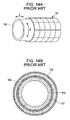
Figs. 14A and 14B show an ultrasonic motor of rotary-and-linear-motion-integrated type and an electronic device including the same as disclosed in Japanese Patent Laid-Open No.10-210776 cylindrical stator 101 and acylindrical mover 102 in contact with an inner or outer surface of thestator 101. Thestator 101 has a cylindricalpiezoelectric element 103, a plurality ofpolarization electrodes 104 regularly arranged on one of the inner surface and the outer surface of thepiezoelectric element 103, and awhole surface electrode 107 provided on the other surface. Themover 102 is driven by ultrasonic vibration generated in thestator 101. In this case, themover 102 can be driven freely in rotary and linear directions by selectively applying a plurality of kinds of out-of-phase alternating voltage to thepolarization electrodes 104. -
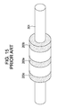
Fig. 15 shows an ultrasonic linear motor disclosed in Japanese Patent Laid-Open No.5-49273 piezoelectric element 203a that vibrates in parallel to the traveling direction, ashaft 201 that penetrates through the firstpiezoelectric element 203a, and second and thirdpiezoelectric elements piezoelectric element 203a and to be able to hold theshaft 201, and that vibrate vertically to the traveling direction. A gap is provided between the firstpiezoelectric element 203a and theshaft 201 in a radial direction. The second and thirdpiezoelectric elements piezoelectric elements shaft 201 at the time of shrinkage and expansion, respectively. The driving speed can be changed by changing a phase difference of alternating voltages applied to the piezoelectric elements. - In general, a vibration actuator according to the related art vibrates either the mover or the stator as a vibrator to generate a friction-based driving force (thrust) in the traveling direction at a contact portion of the mover and the stator.
- In an ultrasonic motor of rotary-and-linear-motion-integrated type disclosed in Japanese Patent Laid-Open No.
10-210776 - Additionally, in an ultrasonic linear motor disclosed in Japanese Patent Laid-Open No.
5-49273 - However, since the vibrator is constituted by the piezoelectric element in the ultrasonic motors disclosed in Japanese Patent Laid-Open Nos.
10-210776 5-49273 - At the time of design and manufacture of an actuator utilizing vibration of a vibrator, the shape of the vibrator and the shape and frequency of a natural vibration mode are essential design parameters directly related to the thrust and the speed of movement. However, since a piezoelectric element is a sintered body, the piezoelectric element does not have a mechanical strength of metal, and mechanical processing methods therefor are also limited. Accordingly, in ultrasonic motors disclosed in Japanese Patent Laid-Open Nos.
10-210776 5-49273 - To realize the high-speed driving, a vibrator has to be vibrated at a significantly high speed in an actuator utilizing vibration. Accordingly, in view of the durability of the actuator, a material of the vibrator has to be resistant to repeated deformation and a structure of the vibrator is preferably simple and irrefrangible. In addition, the material of the vibrator has to have small internal damping in consideration of heat generated in the material.
- Nevertheless, in ultrasonic motors disclosed in Japanese Patent Laid-Open Nos.
10-210776 5-49273 - In addition, since a friction force serving as a driving force is generated in an actuator utilizing vibration, a contact force for keeping a vibrator close to a stator is needed. If this contact force is too weak, the friction force, namely, the driving force, decreases. If the contact force is too strong, the force disturbs vibration of the vibrator and decreases the durability undesirably. Accordingly, it is important to keep the contact force constant in vibration actuators. In the case of cylindrical linear actuators, this contact force is compensated by a fitting accuracy of the vibrator and a circular tube serving as a stator.
- The fitting accuracy of the vibrator and the circular tube significantly changes depending on heat generated in a piezoelectric element and a change in an atmosphere temperature. Thus, a piezoelectric material constituting the vibrator and a material of the stator or the mover preferably have thermal expansion coefficients that are as equal to one another as possible. However, since the circular tube is generally made of metal or the like, a significant difference exists between the thermal expansion coefficients when the vibrator is made of a piezoelectric material, which thus increases an influence of heat.
- In general, a deformation ratio of a piezoelectric element is substantially equal to 10-5. Accordingly, when a piezoelectric element having a diameter of 2 mm is used, deformation of only 2×10⁻⁵ mm = 20 nm is caused. Since surface roughness of the piezoelectric element is much larger than 20 nm, realization of a small linear actuator having a diameter of 2 mm or the like is difficult.
- In addition, the speed of movement in the traveling direction is equal to the product of the driving frequency and the amplitude. Therefore, a small vibration amplitude value equates to a slow movement speed. When the diameter of the piezoelectric element is 2 mm, the amplitude in the circumferential direction is 20 nm, and the component in the traveling direction is 1/10 thereof, the movement speed of the vibrator driven at 50 kHz is 20 nm × 1/10 × 50 kHz = 0.1 mm/s, which is significantly slow.
- The vibrator needs to be vibrated at a large amplitude to realize the high-speed movement. However, if the amplitude becomes too large, fluid, such as air existing in a gap adjacent to a contract portion, is compressed and pressure thereof undesirably levitates the vibrator (ultrasonic levitation). As a result, friction is not generated at the contact portion and the thrust cannot be obtained. That is, large-amplitude vibration undesirably decreases the thrust.
- In view of the unsolved problems involved in the related art, the present invention provides an actuator having a small and simple structure and capable of performing stable high-speed driving.
- The present invention in its first aspect provides an actuator, as specified in
claims 1 to 14. The actuator that moves a mover along a supporting member includes a mover. The mover includes a tubular or plate-like piezoelectric element, a first electrode provided on a first surface of the piezoelectric element, a second electrode provided on a reverse surface to the first surface of the piezoelectric element, and a vibrator having ends which are fixed to the piezoelectric element and a vibration portion which vibrates between the supporting member and the piezoelectric element. In the actuator, a vibration voltage is applied across the first electrode and the second electrode to vibrate the piezoelectric element, the vibration of the piezoelectric element is amplified by the vibrator, and the vibration portion is brought into contact with the supporting member, which thereby moves the mover. - Further features of the present invention will become apparent from the following description of exemplary embodiments with reference to the attached drawings.
-
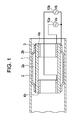
Fig. 1 is a sectional view showing an actuator according to a first exemplary embodiment of the present invention. -
Figs. 2A to 2C are schematic diagrams illustrating a state where a traveling wave is generated in an actuator shown inFig. 1 . -
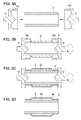
Figs. 3A to 3D are schematic diagrams illustrating a method for manufacturing an actuator shown inFig. 1 . -
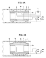
Figs. 4A and 4B are sectional diagrams showing first and second modified examples according to a first exemplary embodiment of the present invention, respectively. -
Fig. 5 is a sectional view showing an actuator according to a second exemplary embodiment of the present invention. -
Fig. 6 is a sectional view showing an actuator according to a third exemplary embodiment of the present invention. -
Fig. 7 is a sectional view showing an actuator according to a fourth exemplary embodiment of the present invention. -
Figs. 8A to 8C are schematic diagrams illustrating driving signals used in an actuator shown inFig. 7 . -
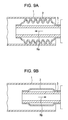
Figs. 9A and 9B are schematic diagrams illustrating a method of driving an actuator shown inFig. 7 . -
Fig. 10 is a sectional view showing a modified example of an actuator according to a fourth exemplary embodiment of the present invention. -
Fig. 11 is a sectional view showing an actuator according to a fifth exemplary embodiment of the present invention. -
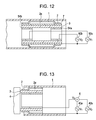
Fig. 12 is a sectional view showing an actuator according to a sixth exemplary embodiment of the present invention. -
Fig. 13 is a sectional view showing an actuator according to a seventh exemplary embodiment of the present invention. -
Figs. 14A and 14B are schematic diagrams showing an actuator according to the related art. -
Fig. 15 is a schematic diagram showing an actuator according to the related art. - Exemplary embodiments of the present invention will be described with reference to the attached drawings.
-
Fig. 1 shows an actuator according to a first exemplary embodiment of the present invention. Atubular member 1 is a cylindrical member functioning as a stator. Avibrator 2 is a cylindrical member. A diameter of an axial central portion of thevibrator 2 is larger than that of end portions thereof and the vibrator has a central-portion-swollen shape. This swollen portion is arranged to fit thetubular member 1. Thevibrator 2 is formed of metal, such as stainless, or metal glass. Apiezoelectric element 3 is a cylindrical member and is fixed to an inner surface of thevibrator 2 at both end portions. Agap 2a is formed between the central portion of thevibrator 2 and thepiezoelectric element 3. - A first electrode (segmented electrode) 4a and a second electrode (segmented electrode) 4b are provided at the respective end portions of the inner surface of the
piezoelectric element 3. Alternatingpower supplies first electrode 4a and thevibrator 2 and across thesecond electrode 4b and thevibrator 2, whereby thepiezoelectric element 3 vibrates. Accordingly, thevibrator 2 also functions as a common electrode. The vibration of thepiezoelectric element 3 is amplified by thevibrator 2 and a change in a friction force generated at a contact portion of thevibrator 2 and thetubular member 1 is converted into a driving force, whereby a mover including thevibrator 2 and thepiezoelectric element 3 relatively moves in an axial direction of thetubular member 1. -
Figs. 2A to 2C are schematic diagrams illustrating a principle of converting vibration of thevibrator 2 into a driving force.Figs. 2A to 2C exaggeratedly show the vibration amplitude for the purpose of explanation. Referring toFig. 2A , a sine-wave vibration voltage Va is applied across thefirst electrode 4a and thevibrator 2 by the alternatingpower supply 10a. - As shown by
Fig. 2B , the vibration voltage Va applied across thefirst electrode 4a and thevibrator 2 causes the cylindricalpiezoelectric element 3 to vibrate in a diameter direction shown by an arrow R1. This vibration causes thevibrator 2 to vibrate in a vibration mode having a vibration amplitude in the diameter direction at the end portion of thevibrator 2 near thefirst electrode 4a. - The vibration generated at the end portion of the
vibrator 2 near thefirst electrode 4a is converted into a traveling wave that travels in the axial direction of thevibrator 2, which is shown by an arrow R2 along thevibrator 2. The amplitude of this traveling wave gradually becomes smaller due to the friction between thevibrator 2 and thetubular member 1 in contact with thevibrator 2 and the internal damping of thevibrator 2, and reaches the end portion of thevibrator 2 near thesecond electrode 4b. - In this exemplary embodiment, the mover including the
vibrator 2 and thepiezoelectric element 3 is relatively moved in the axial direction of thetubular member 1 utilizing this traveling wave. In general, a wave whose wave front travels in one direction is referred to as a traveling wave, whereas a wave whose wave front does not travel due to an interference with a wave reflected at an end portion is referred to as a standing wave. To prevent the traveling wave from becoming the standing wave due to the reflection, the vibration has to be absorbed at the end portion opposite to the vibration-generating side. - Accordingly, as shown in
Fig. 2A , the alternatingpower supply 10b applies a sine-wave vibration voltage Vb across thesecond electrode 4b and thevibrator 2 in this exemplary embodiment. The vibration voltage Vb has the same frequency as the vibration voltage Va but has different phase and amplitude. By optimizing the phase and amplitude of the vibration voltage Vb, the above-described traveling wave can be absorbed on the side of thesecond electrode 4b of thevibrator 2. That is, the traveling wave is maintained without being converted into the standing wave. -
Fig. 2C is a schematic diagram illustrating a principle of relatively moving a mover including thevibrator 2 and thepiezoelectric element 3 in the axial direction of thetubular member 1 using a traveling wave that travels in a direction of an arrow R2. - A traveling wave that travels in the direction shown by the arrow R2 is generated in the
vibrator 2, which is in contact with thetubular member 1. The traveling wave causes thevibrator 2 to elliptically vibrate in a direction shown by an arrow R3. This elliptic vibration pushes thetubular member 1 that is in contact with thevibrator 2 in a direction shown by an arrow R4, which is opposite to the direction of the traveling wave. In this manner, thetubular member 1 relatively moves in the direction of the arrow R4 with respect to thevibrator 2. - At this time, as the amplitude of the elliptic vibration increases, the force (driving force) of pushing the
tubular member 1 becomes stronger and the movement speed increases, which is thus preferable as characteristics of an actuator. In this exemplary embodiment, the vibration of thepiezoelectric element 3 is amplified using thevibrator 2. At this time, the amplitude is amplified utilizing a natural vibration mode of thevibrator 2. More specifically, if vibration is applied to a portion near a "node" of the vibration mode, a significantly large amplitude is obtained at a portion near a "loop" of the vibration mode due to resonance. Accordingly, the amplitude of the vibration of thevibrator 2 can be increased using resonance by setting frequencies of the vibration voltages Va and Vb to match the natural frequency of thevibrator 2. - Meanwhile, to change the moving direction of the actuator, the traveling direction of the traveling wave is changed to the opposite direction. More specifically, the vibration voltage Va is applied across the
second electrode 4b and thevibrator 2 and the vibration voltage Vb is applied across thefirst electrode 4a and thevibrator 2. - Smooth R-shaped
connection portions 2b of thevibrator 2 are formed at portions near the respective end portions. The durability can be significantly improved with this R-shape. Since thisconnection portion 2b includes a region receiving strong stress caused by the excitation force of thepiezoelectric element 3, it is important to smoothly connect this region particularly. This R-shape prevents the stress from focusing on one point and improves the strength of thevibrator 2. As a result, the durability is improved and vibration can be generated at a larger amplitude, which makes it possible to provide an actuator capable of performing high-speed driving. -
Figs. 3A to 3D are schematic diagrams illustrating a method for manufacturing thevibrator 2. - As shown in
Fig. 3A , first caps 11 are put on the respective ends of the cylindricalpiezoelectric element 3. Eachcap 11 has amask portion 11a having an inside diameter larger than an outside diameter of thepiezoelectric element 3. Themask portion 11a masks the respective end portions of thepiezoelectric element 3. - As shown in
Fig. 3B , thepiezoelectric element 3 with the first caps 11 on, is then put into a spatter film deposition apparatus (not shown) and asacrificial layer 12 is formed while rotating thepiezoelectric element 3. At this time, since the above-describedmask portions 11a exist, the thickness of thesacrificial layer 12 gradually decreases toward the ends. A metal dissolvable in acid and alkali, such as aluminum, and a macromolecular material dissolvable in organic solvent can be used as a material of thesacrificial layer 12. - As shown in
Fig. 3C , second caps 13 are then put on the respective ends of thepiezoelectric element 3. A film serving as thevibrator 2 is formed on thesacrificial layer 12 while rotating thepiezoelectric element 3. A material highly resistant to repeatedly applied stress is preferable as a material of thevibrator 2. For example, a material of stainless series or a material of metallic glass series is preferable. Particularly, the metallic glass is composed of amorphous metal atoms. Since the metallic glass is amorphous, the metallic glass shows high durability unlike a normal metal. More specifically, the amorphous has a high hardness and can improve the abrasion resistance. In addition, manufacture of thetubular member 1 with the metallic glass can improve the abrasion resistance. As a result, an actuator having much higher durability can be realized. - As shown in
Fig. 3D , thesacrificial layer 12 is then dissolved to form agap 2a between thevibrator 2 and thepiezoelectric element 3. At this time, to bring solvent for dissolving thesacrificial layer 12 into contact with thesacrificial layer 12, thevibrator 2 having a plurality of minute holes formed using a laser or the like can be used. Since formation of the holes in thevibrator 2 allows compressed air to escape through the holes even if the air existing in the gap adjacent to the contact portion is compressed, the pressure does not increase. Accordingly, levitation of thevibrator 2 can be prevented. As a result, the thrust does not decrease even if thevibrator 2 vibrates at a large amplitude. - The
connection portion 2b of thevibrator 2 and thepiezoelectric element 3 can be formed in a smooth R-shape by manufacturing thevibrator 2 in this manner. - Although the
vibrator 2 serves as a common electrode in this exemplary embodiment, a conductive thin film serving as the common electrode may be provided on one side of thepiezoelectric element 3. However, since one electrode can be omitted when theconductive vibrator 2 is used as the common electrode, the structure can be simplified. - In addition, the gap between the
vibrator 2 and thepiezoelectric element 3 may be filled with a sufficiently soft material that does not affect vibration of thevibrator 2. A silicon rubber having low hardness is preferable as such a soft material. If such a soft material is used as thesacrificial layer 12 at the above-described manufacturing step and the sacrificial layer is left as it is, the manufacture becomes easier and the cost is advantageously reduced since a step of removing thesacrificial layer 12 is not needed. - If the
vibrator 2 is partially brought into contact with and out of contact with thetubular member 1 serving as a supporting member repeatedly in response to vibration of thevibrator 2, the air pressure may prevent thevibrator 2 from being in contact with thetubular member 1. This phenomenon is called ultrasonic levitation. The plurality of minute holes formed in thevibrator 2 can prevent this ultrasonic levitation. - Instead of using the
vibrator 2 having minute holes formed thereon,holes 3a are formed on thepiezoelectric element 3 in advance and may be filled with the same material as thesacrificial layer 12, as shown inFig. 4A . By connecting theholes 3a provided on thepiezoelectric element 3 to a passage to be connected to arefrigerant circulation pump 5, the refrigerant can be circulated through thegap 2a. If thepiezoelectric element 3 is vibrated at a high speed and a large amplitude, an amount of generated heat increases. By introducing the refrigerant to thegap 2a between thepiezoelectric element 3 and thevibrator 2, this heat can be removed. As a result, an increase in the temperature of thepiezoelectric element 3 and thevibrator 2 can be suppressed. - The contact portion of the
vibrator 2 and thetubular member 1 does not have to be flat. Thevibrator 2 may be in the shape of a corrugated plate having awaveshape portion 2c as shown inFig. 4B . Thevibrator 2 in the shape of the corrugated plate can be readily manufactured by forming netlike masking at the time of deposition of thesacrificial layer 12. - During vibration of the
vibrator 2, the pressure of air existing between thevibrator 2 and thetubular member 1 levitates thevibrator 2. That is, so-called ultrasonic levitation is caused. However, since the corrugated plate of thevibrator 2 allows compressed air to escape from the grooves of the corrugated plate even if the air existing in the gap adjacent to the contact portion is compressed, the pressure does not increase. Accordingly, the levitation of thevibrator 2 can be prevented. As a result, the thrust does not reduce even if thevibrator 2 vibrates at a large amplitude. -
Fig. 5 is a sectional view showing an actuator according to a second exemplary embodiment of the present invention. Referring back toFig. 1 showing the actuator according to the first exemplary embodiment, the mover including thevibrator 2 and thepiezoelectric element 3 relatively moves inside of thetubular member 1. On the other hand, in this exemplary embodiment, a mover including acylindrical vibrator 22 and apiezoelectric element 23 relatively moves outside of atubular member 21, which is a solid pipe. - The
vibrator 22 is a cylindrical member. The diameter of an axial central portion is smaller than that of end portions. Thevibrator 22 is in a shape in which the central portion is concave. This concave portion is arranged to fit thetubular member 21. Apiezoelectric element 23 is a cylindrical member and is fixed to an outer surface of thevibrator 22 at both end portions. Agap 22a is formed between the central portion of thevibrator 22 and thepiezoelectric element 23. - A first electrode (segmented electrode) 24a and a second electrode (segmented electrode) 24b are provided at the respective end portions of the outer surface of the
piezoelectric element 23. Alternatingpower supplies first electrode 24a and thevibrator 22 and across thesecond electrode 24b and thevibrator 22, respectively, whereby thepiezoelectric element 23 vibrates. Accordingly, thevibrator 22 also functions as a common electrode. The vibration of thepiezoelectric element 23 is amplified by thevibrator 22 and a change in a friction force generated at a contact portion of thevibrator 22 and thetubular member 21 is converted into a driving force, whereby a mover including thevibrator 22 and thepiezoelectric element 23 relatively moves in an axial direction of thetubular member 21. - Meanwhile, since the same driving method as that of the first exemplary embodiment is employed in this exemplary embodiment, a description thereof is omitted here. In addition, this exemplary embodiment offers advantages similar to those of the first exemplary embodiment.
-
Fig. 6 is a sectional view showing an actuator according to a third exemplary embodiment of the present invention. In this exemplary embodiment, a plate-like body 31, which is a plate-like supporting member, and a mover including a plate-like vibrator 32 and a plate-likepiezoelectric element 33 are used. Both end portions of thevibrator 32 are fixed to thepiezoelectric element 33. Agap 32a is formed at a central portion serving as a vibration portion. -
Smooth connection portions 32b of the plate-like vibrator 32 are connected to thepiezoelectric element 33 at portions near the respective end portions. An R-shape of theconnection portion 32b can significantly improve the durability. A central portion of thevibrator 32 is in contact with the plate-like body 31. Here, suppose that a direction of gravity is the downward direction. At this time, since thevibrator 32 is pressed onto the plate-like body 31 due to the weight thereof, thevibrator 32 is not levitated and the contact state is maintained. - As in the case of the above-described first exemplary embodiment, a
first electrode 34a and asecond electrode 34b are provided on the respective end portions of thepiezoelectric element 33. Alternatingpower supplies first electrode 34a and thevibrator 32 and across thesecond electrode 34b and thevibrator 32, respectively, whereby thepiezoelectric element 33 vibrates. The vibration of thepiezoelectric element 33 generated by the vibration voltages Va and Vb is transferred to thevibrator 32 and generates a traveling wave in thevibrator 32. Thevibrator 32 moves relative to the plate-like body 31 in contact with thevibrator 32. - According to this exemplary embodiment, since the supporting member can be constituted by a plate-like member, the
vibrator 32 can be manufactured simply by using a film deposition method, such as spattering. In addition, the above-described force of gravity is not only the force that can be utilized, and forces generated with a spring and a magnet can also be utilized as the pressing force for keeping thevibrator 32 in contact with the plate-like body 31 serving as the supporting member. - A fourth exemplary embodiment of the present invention will now be described with reference to
Fig. 7 to Fig. 9B . In this exemplary embodiment, a description will be given on a configuration of a linear actuator utilizing a standing wave instead of a traveling wave utilized in the first exemplary embodiment. ThroughFig. 7 to Fig. 9B , the same or like numerals are attached to members common to those shown inFig. 1 and a description thereof is omitted. - A difference between
Fig. 7 andFig. 1 is that thefirst electrode 4a and thesecond electrode 4b are replaced with anelectrode 4 which is formed on an inner surface of apiezoelectric element 3 inFig. 7 . In addition, a vibration voltage V1 of an alternatingpower supply 40a and a vibration voltage V2 of an alternatingpower supply 40b are combined by an addingcircuit 6 and are applied across avibrator 2 and theelectrode 4 as a third vibration voltage V3. Accordingly, the third vibration voltage V3 is applied to both ends of thevibrator 2. - A description will be given on a principle of relatively moving a mover including the
vibrator 2 and thepiezoelectric element 3 in an axial direction of atubular member 1 using the vibration voltage V3, which is a standing wave. - If the alternating
power supply 40a applies the first vibration voltage V1 shown inFig. 8A across thevibrator 2 and theelectrode 4, thepiezoelectric element 3 vibrates in the diameter direction. The first vibration voltage V1 intermittently fluctuates at a frequency matching a natural frequency of thevibrator 2.
Propagation of this vibration to thevibrator 2 vibrates thevibrator 2 and a standing wave that fluctuates in the diameter direction in a vibration mode having a vibration amplitude is generated as shown inFig. 9A . This standing wave is a natural vibration mode of thevibrator 2, resonates at a predetermined frequency, and can provide a large amplitude. Based on this vibration, thetubular member 1 arranged on the outer side of thevibrator 2 is repeatedly brought into contact with and out of contact with thevibrator 2. - If the alternating
power supply 40b applies the second vibration voltage V2 shown inFig. 8B across thevibrator 2 and theelectrode 4, thepiezoelectric element 3 deforms not only in the diameter direction but also in the axial direction indicated by arrows Ra and Rb shown inFigs. 9A and 9B , respectively. Thepiezoelectric element 3 repeats a motion of expanding in the direction of the arrow Ra and a motion of shrinking in the direction of the arrow Rb. - Accordingly, if the first vibration voltage V1 is applied at the time of expansion of the
piezoelectric element 3 in the direction of the arrow Ra caused by the second vibration voltage V2, thevibrator 2 is brought into contact with thetubular member 1 and thetubular member 1 can be pushed in the direction of the arrow Ra by a friction force. Conversely, if the level of the first vibration voltage V1 is lowered to make the vibration amplitude smaller at the time of shrinkage ofpiezoelectric element 3 in the direction of the arrow Rb caused by the second vibration voltage V2, the friction force between thevibrator 2 and thetubular member 1 becomes significantly small and thetubular member 1 is kept fixed. - Accordingly, states shown in
Figs. 9A and 9B are repeated by applying the third vibration voltage V3, shown inFig. 8C , obtained by combining the first vibration voltage V1 and the second vibration voltage V2. This relatively moves the mover including thevibrator 2 and thepiezoelectric element 3 in the axial direction of thetubular member 1. - Meanwhile, the vibration voltages V1 and V2 may be separately applied instead of using the above-described third vibration voltage V3 in a method of vibrating the
piezoelectric element 3 using two kinds of vibration voltage V1 and V2. In this case, the actuator has to be configured so that the vibration voltages V1 and V2 can be separately applied to theelectrode 4 as shown inFig. 10 . - To change the moving direction of the actuator, the first vibration voltage V1 is applied at the time of shrinkage of the
piezoelectric element 3 in the direction of the arrow Rb and the level of the first vibration voltage V1 is lowered at the time of expansion of thepiezoelectric element 3 in the direction of the arrow Ra. Accordingly, the moving direction can be changed by changing the phases of two kinds of vibration voltage V1 and V2. -
Fig. 11 is a sectional view showing an actuator according to a fifth exemplary embodiment of the present invention. A difference between this exemplary embodiment and the fourth exemplary embodiment is that theelectrode 4 is segmented into three. As shown inFig. 11 , two electrodes (segmented electrodes) 44a and 44b are located at respective end portions and an electrode (segmented electrode) 44c is located at a central portion. - A vibration voltage V1 of an alternating
power supply 50a is applied to theelectrodes power supply 50b is applied to theelectrode 44c located at the central portion. If the vibration voltage V1 is applied to both end portions at the same time of shrinkage of apiezoelectric element 3 in the axial direction caused by the vibration voltage V2, avibrator 2 is vibrated and the wave front of the standing wave touches atubular member 1. By repeating this action, a mover including thevibrator 2 and thepiezoelectric element 3 relatively moves in the axial direction of thetubular member 1. -
Fig. 12 is a sectional view showing an actuator according to a sixth exemplary embodiment of the present invention. Unlike the above-described fourth exemplary embodiment, theelectrode 4 is segmented into two in this exemplary embodiment. As shown inFig. 12 , two electrodes (segmented electrodes) 54a and 54b are provided at respective end portions. In addition, acommon electrode 7 is provided between avibrator 2 and apiezoelectric element 3. - Vibration voltages V1 and V2 of alternating
power supplies electrodes piezoelectric element 3 in the axial direction caused by the vibration voltage V2, thevibrator 2 is vibrated and the wave front of the standing wave touches atubular member 1. By repeating this action, a mover including thevibrator 2 and thepiezoelectric element 3 relatively moves in the axial direction of thetubular member 1. - Since the
common electrode 7 is provided separately from thevibrator 2, the electrode can be formed using a low-resistance material, such as, for example, copper and gold. Since generation of heat due to the current flowing through the electrodes can be suppressed, an increase in temperature is advantageously suppressed. -
Fig. 13 is a sectional view showing an actuator according to a seventh exemplary embodiment of the present invention. In this exemplary embodiment, the mover including thevibrator 2 and thepiezoelectric element 3 according to the fourth exemplary embodiment is cut into half at a plane vertical to the axis, resulting in avibrator 2, apiezoelectric element 3, andelectrode 4, and agap 2a. The same driving method as that of the fourth exemplary embodiment is employed. - While the present invention has been described with reference to exemplary embodiments, it is to be understood that the invention is not limited to the disclosed exemplary embodiments. The scope of the following claims is to be accorded the broadest interpretation so as to encompass all modifications and equivalent structures and functions.
A cylindrical piezoelectric element (3) is arranged to share an axis with a cylindrical vibrator (2) having different diameters at central and end portions to fix the vibrator (2) forming a gap (2a) at the central portion. Vibration voltages are applied across first electrodes (4a, 4b) on the piezoelectric element (3) and the vibrator (2), namely, a second electrode, to vibrate the vibrator (2) and bring a wave front of a traveling wave into contact with a tubular member (1), i.e., a supporting member fitted to the vibrator (2). Friction at a contact portion of the vibrator (2) moves a mover including the vibrator (2) and the piezoelectric element (3) in an axial direction of the tubular member (1). By amplifying the vibration amplitude using the vibrator (2) provided separately from the piezoelectric element (3), a small actuator capable of performing high-speed driving is realized.
Claims (14)
- An actuator that moves a mover along a supporting member, comprising:a supporting member (1, 21, or 31);a mover arranged to relatively move along the supporting member, the mover includinga piezoelectric element (3),a first electrode (4a or 34a) provided at one end portion of a first surface of the piezoelectric element,a second electrode (4b or 34b) provided at the other end portion of the first surface of the piezoelectric element, anda vibrator (2 or 32), wherein one end of the vibrator is fixed to a reverse surface to the first surface of the piezoelectric element, the other end of the vibrator is fixed to the reverse surface to the first surface of the piezoelectric element, and a central portion of the vibrator is arranged to be in contact with the supporting member; andpower supply means (10a, 10b, 30a, or 30b) arranged to apply a voltage to the first electrode, the second electrode, and the vibrator,wherein the voltage is applied across the first electrode and the vibrator and across the second electrode and the vibrator to vibrate the piezoelectric element, the vibration of the piezoelectric element is amplified by the vibrator, and the amplified vibration is transferred to the supporting member through the vibrator, which thereby moves the mover along the supporting member.
- The actuator according to Claim 1, wherein the supporting member (1) is a tubular member, the piezoelectric element (3) is a tubular member, the vibrator (2) is a tubular member located on an outer side of the piezoelectric element (3), and the mover including the vibrator (2) and the piezoelectric element (3) moves in an axial direction of the supporting member along an inner surface of the supporting member.
- The actuator according to Claim 1, wherein the supporting member (21) is a cylindrical member or a columnar member, the piezoelectric element (23) is a tubular member, the vibrator (22) is a tubular member located on an inner side of the piezoelectric element (23), and the mover including the vibrator (22) and the piezoelectric element (23) moves in an axial direction of the supporting member along an outer surface of the supporting member.
- The actuator according to Claim 1, wherein the supporting member (31) is a plate-like member, the piezoelectric element (33) is a plate-like member, the vibrator (32) is a plate-like member located between the supporting member (31) and the piezoelectric element (33), and the mover including the vibrator (32) and the piezoelectric element (33) moves along an upper surface of the supporting member.
- The actuator according to Claims 2 to 4, wherein the mover is moved by a friction generated at a contact portion of the supporting member and a wave front of the mover.
- The actuator according to Claims 2 to 4, wherein the vibration of the piezoelectric element is a traveling wave generated at a vibration portion of the vibrator by applying vibration voltages having a same frequency but different phases and amplitudes across the first electrode and the vibrator and across the second electrode and the vibrator.
- The actuator according to Claims 2 to 4, wherein the vibration of the piezoelectric element is a standing wave generated at a vibration portion of the vibrator by alternately applying, across the first electrode and the vibrator and across the second electrode and the vibrator, a combined wave of a first vibration voltage that causes the piezoelectric element to shrink in an axial direction and an intermittent second vibration voltage that has a same frequency as a natural frequency of the vibrator at a time of an increase or a decrease in the first vibration voltage.
- The actuator according to Claims 2 to 4, wherein the vibration of the piezoelectric element is a standing wave generated at a vibration portion of the vibrator by alternately applying, across the first electrode and the vibrator and across the second electrode and the vibrator, a first vibration voltage that causes the piezoelectric element to shrink in an axial direction and an intermittent second vibration voltage that has a same frequency as a natural frequency of the vibrator at a time of an increase or a decrease in the first vibration voltage.
- The actuator according to Claims 2 to 4, wherein the first electrode and the second electrode are integrated into a single electrode, and
wherein a standing wave is generated at a vibration portion of the vibrator by applying, across the single integrated electrode and the vibrator, a combined wave of a first vibration voltage that causes the piezoelectric element to shrink in an axial direction and an intermittent second vibration voltage that has a same frequency as a natural frequency of the vibrator at a time of an increase or a decrease in the first vibration voltage. - The actuator according to Claims 1 to 9, wherein a plurality of minute holes are provided in the vibrator.
- The actuator according to Claims 1 to 9, wherein the vibrator is in a shape of a corrugated plate.
- The actuator according to Claims 1 to 9, wherein a portion between a vibration portion of the vibrator and the piezoelectric element is filled with a soft material.
- The actuator according to Claims 1 to 9, wherein piping means arranged to introduce a refrigerant to a portion between a vibration portion of the vibrator and the piezoelectric element and to circulate the refrigerant is provided.
- The actuator according to Claims 1 to 9, wherein a vibration portion of the vibrator or the supporting member is formed of metallic glass.
Applications Claiming Priority (2)
| Application Number | Priority Date | Filing Date | Title |
|---|---|---|---|
| JP2007189001 | 2007-07-20 | ||
| JP2008155357A JP5159452B2 (en) | 2007-07-20 | 2008-06-13 | Actuator |
Publications (3)
| Publication Number | Publication Date |
|---|---|
| EP2017905A2 true EP2017905A2 (en) | 2009-01-21 |
| EP2017905A3 EP2017905A3 (en) | 2012-07-11 |
| EP2017905B1 EP2017905B1 (en) | 2014-03-19 |
Family
ID=39855118
Family Applications (1)
| Application Number | Title | Priority Date | Filing Date |
|---|---|---|---|
| EP08160022.3A Ceased EP2017905B1 (en) | 2007-07-20 | 2008-07-09 | Actuator |
Country Status (2)
| Country | Link |
|---|---|
| US (1) | US7915787B2 (en) |
| EP (1) | EP2017905B1 (en) |
Cited By (1)
| Publication number | Priority date | Publication date | Assignee | Title |
|---|---|---|---|---|
| CN107041120A (en) * | 2017-05-12 | 2017-08-11 | 广州中国科学院先进技术研究所 | A kind of slow-wave component shell cold extrusion device |
Families Citing this family (12)
| Publication number | Priority date | Publication date | Assignee | Title |
|---|---|---|---|---|
| CN101160711B (en) * | 2005-12-05 | 2013-03-20 | 松下电器产业株式会社 | Ultrasonic actuator |
| DE102008023478A1 (en) * | 2007-11-08 | 2009-05-14 | Physik Instrumente (Pi) Gmbh & Co. Kg | Ultrasonic linear drive with hollow cylindrical oscillator |
| JP4677493B2 (en) * | 2008-01-22 | 2011-04-27 | キヤノン株式会社 | Piezoelectric vibration type force sensor |
| DE102008057389B4 (en) * | 2008-11-14 | 2011-03-17 | Fraunhofer-Gesellschaft zur Förderung der angewandten Forschung e.V. | Transporting an object over a surface |
| JP5429141B2 (en) * | 2010-01-19 | 2014-02-26 | Tdk株式会社 | Piezoelectric actuator and method for manufacturing piezoelectric actuator |
| JP5743495B2 (en) * | 2010-11-05 | 2015-07-01 | キヤノン株式会社 | Robot controller |
| JP5884303B2 (en) * | 2011-06-07 | 2016-03-15 | セイコーエプソン株式会社 | Piezoelectric actuator, robot hand, and robot |
| JP5896789B2 (en) | 2012-03-07 | 2016-03-30 | キヤノン株式会社 | Robot control apparatus, robot apparatus, robot control method, program, and recording medium |
| JP6238628B2 (en) | 2013-08-06 | 2017-11-29 | キヤノン株式会社 | Robot device, robot control method, robot control program, and part manufacturing method using robot device |
| JP6700669B2 (en) | 2015-04-07 | 2020-05-27 | キヤノン株式会社 | Control method, robot device, program, recording medium, and article manufacturing method |
| US11045950B2 (en) | 2018-11-02 | 2021-06-29 | Canon Kabushiki Kaisha | Driving device and detecting device |
| US11193354B2 (en) * | 2018-12-07 | 2021-12-07 | Baker Hughes Holdings Llc | Motors for downhole tools devices and related methods |
Citations (3)
| Publication number | Priority date | Publication date | Assignee | Title |
|---|---|---|---|---|
| JPH0472471A (en) | 1990-07-11 | 1992-03-06 | Toshiba Corp | Feedwater heater drain pump up system |
| JPH0549273A (en) | 1991-08-06 | 1993-02-26 | Seiko Epson Corp | Ultrasonic linear motor |
| JPH10210776A (en) | 1997-01-27 | 1998-08-07 | Toshiba Corp | Rotary / linear motion integrated ultrasonic motor and electronic device incorporating the same |
Family Cites Families (9)
| Publication number | Priority date | Publication date | Assignee | Title |
|---|---|---|---|---|
| AT384912B (en) * | 1982-04-16 | 1988-01-25 | Ki Polt I | PIEZOELECTRIC MOTOR |
| US4560263A (en) * | 1982-12-03 | 1985-12-24 | Canon Kabushiki Kaisha | Drive system for a vibration wave motor for lens control |
| JP2687233B2 (en) * | 1989-02-10 | 1997-12-08 | キヤノン株式会社 | Sheet feeder |
| US5332941A (en) * | 1992-02-21 | 1994-07-26 | Honda Electronics Co., Ltd. | Ultrasonic driving motor |
| US5396142A (en) * | 1994-01-24 | 1995-03-07 | Evan Koblanski | Positioning apparatus |
| JPH10337057A (en) * | 1997-06-02 | 1998-12-18 | Minolta Co Ltd | Driver |
| DE50014572D1 (en) * | 1999-11-29 | 2007-09-27 | Miniswys Sa | PIEZOELECTRIC DRIVE |
| ATE335302T1 (en) * | 2002-03-15 | 2006-08-15 | Miniswys Sa | PIEZOELECTRIC MOTOR AND METHOD FOR DRIVING THE SAME |
| KR101138397B1 (en) * | 2005-09-27 | 2012-04-26 | 삼성전자주식회사 | Piezoelectric actuator, apparatus and method for operating it |
-
2008
- 2008-07-08 US US12/169,575 patent/US7915787B2/en not_active Expired - Fee Related
- 2008-07-09 EP EP08160022.3A patent/EP2017905B1/en not_active Ceased
Patent Citations (3)
| Publication number | Priority date | Publication date | Assignee | Title |
|---|---|---|---|---|
| JPH0472471A (en) | 1990-07-11 | 1992-03-06 | Toshiba Corp | Feedwater heater drain pump up system |
| JPH0549273A (en) | 1991-08-06 | 1993-02-26 | Seiko Epson Corp | Ultrasonic linear motor |
| JPH10210776A (en) | 1997-01-27 | 1998-08-07 | Toshiba Corp | Rotary / linear motion integrated ultrasonic motor and electronic device incorporating the same |
Cited By (1)
| Publication number | Priority date | Publication date | Assignee | Title |
|---|---|---|---|---|
| CN107041120A (en) * | 2017-05-12 | 2017-08-11 | 广州中国科学院先进技术研究所 | A kind of slow-wave component shell cold extrusion device |
Also Published As
| Publication number | Publication date |
|---|---|
| EP2017905B1 (en) | 2014-03-19 |
| US7915787B2 (en) | 2011-03-29 |
| US20090021113A1 (en) | 2009-01-22 |
| EP2017905A3 (en) | 2012-07-11 |
Similar Documents
| Publication | Publication Date | Title |
|---|---|---|
| EP2017905B1 (en) | Actuator | |
| JP5159452B2 (en) | Actuator | |
| Watson et al. | Piezoelectric ultrasonic micro/milli-scale actuators | |
| CN102215010B (en) | Vibration type actuator, vibrator, and vibrator manufacturing method | |
| JP4943618B2 (en) | Vibration motor and method of manufacturing and using the same | |
| US20030234596A1 (en) | Near-resonance electromechanical motor | |
| JP2012500503A (en) | Quasi-resonant drive system and method | |
| JPH10262381A (en) | Electrostatic actuator using alternating voltage pattern | |
| EP3319219A1 (en) | Ultrasonic actuator | |
| JP4435695B2 (en) | Piezoelectric motor operation method and piezoelectric motor in the form of a hollow cylindrical oscillator having a stator | |
| US11050364B2 (en) | Semi-resonant motion devices and methods thereof | |
| JP5218045B2 (en) | Vibration actuator, lens barrel, camera system, and driving method of vibration actuator | |
| US5831370A (en) | Vibration actuator | |
| JP4871594B2 (en) | Vibration wave drive device and vibration wave drive device | |
| JPH08140377A (en) | Ultrasonic actuator | |
| EP4275462B1 (en) | Mounting arrangement for piezo motor element | |
| JP2010206950A (en) | Actuator | |
| KR100661311B1 (en) | Piezoelectric ultrasonic motor | |
| JP4491888B2 (en) | Vibration actuator | |
| JP3074379B2 (en) | Rotary piezoelectric actuator | |
| JP2009055779A (en) | Ultrasonic actuator, magnetic recording apparatus | |
| JPH09205782A (en) | Vibration actuator drive | |
| JP2004289894A (en) | Ultrasonic motor | |
| CN120212361A (en) | A petroleum pipeline inspection robot and its excitation method | |
| JPH0635676Y2 (en) | Ultrasonic linear motor |
Legal Events
| Date | Code | Title | Description |
|---|---|---|---|
| PUAI | Public reference made under article 153(3) epc to a published international application that has entered the european phase |
Free format text: ORIGINAL CODE: 0009012 |
|
| AK | Designated contracting states |
Kind code of ref document: A2 Designated state(s): AT BE BG CH CY CZ DE DK EE ES FI FR GB GR HR HU IE IS IT LI LT LU LV MC MT NL NO PL PT RO SE SI SK TR |
|
| AX | Request for extension of the european patent |
Extension state: AL BA MK RS |
|
| PUAL | Search report despatched |
Free format text: ORIGINAL CODE: 0009013 |
|
| AK | Designated contracting states |
Kind code of ref document: A3 Designated state(s): AT BE BG CH CY CZ DE DK EE ES FI FR GB GR HR HU IE IS IT LI LT LU LV MC MT NL NO PL PT RO SE SI SK TR |
|
| AX | Request for extension of the european patent |
Extension state: AL BA MK RS |
|
| RIC1 | Information provided on ipc code assigned before grant |
Ipc: H02N 2/08 20060101ALI20120605BHEP Ipc: H01L 41/09 20060101AFI20120605BHEP |
|
| 17P | Request for examination filed |
Effective date: 20130111 |
|
| AKX | Designation fees paid |
Designated state(s): DE FR GB IT NL |
|
| GRAP | Despatch of communication of intention to grant a patent |
Free format text: ORIGINAL CODE: EPIDOSNIGR1 |
|
| INTG | Intention to grant announced |
Effective date: 20131007 |
|
| GRAS | Grant fee paid |
Free format text: ORIGINAL CODE: EPIDOSNIGR3 |
|
| GRAA | (expected) grant |
Free format text: ORIGINAL CODE: 0009210 |
|
| AK | Designated contracting states |
Kind code of ref document: B1 Designated state(s): DE FR GB IT NL |
|
| REG | Reference to a national code |
Ref country code: GB Ref legal event code: FG4D |
|
| REG | Reference to a national code |
Ref country code: DE Ref legal event code: R096 Ref document number: 602008030935 Country of ref document: DE Effective date: 20140430 |
|
| REG | Reference to a national code |
Ref country code: NL Ref legal event code: VDEP Effective date: 20140319 |
|
| PG25 | Lapsed in a contracting state [announced via postgrant information from national office to epo] |
Ref country code: NL Free format text: LAPSE BECAUSE OF FAILURE TO SUBMIT A TRANSLATION OF THE DESCRIPTION OR TO PAY THE FEE WITHIN THE PRESCRIBED TIME-LIMIT Effective date: 20140319 |
|
| REG | Reference to a national code |
Ref country code: DE Ref legal event code: R097 Ref document number: 602008030935 Country of ref document: DE |
|
| PLBE | No opposition filed within time limit |
Free format text: ORIGINAL CODE: 0009261 |
|
| STAA | Information on the status of an ep patent application or granted ep patent |
Free format text: STATUS: NO OPPOSITION FILED WITHIN TIME LIMIT |
|
| 26N | No opposition filed |
Effective date: 20141222 |
|
| PG25 | Lapsed in a contracting state [announced via postgrant information from national office to epo] |
Ref country code: IT Free format text: LAPSE BECAUSE OF FAILURE TO SUBMIT A TRANSLATION OF THE DESCRIPTION OR TO PAY THE FEE WITHIN THE PRESCRIBED TIME-LIMIT Effective date: 20140319 |
|
| REG | Reference to a national code |
Ref country code: DE Ref legal event code: R097 Ref document number: 602008030935 Country of ref document: DE Effective date: 20141222 |
|
| REG | Reference to a national code |
Ref country code: FR Ref legal event code: PLFP Year of fee payment: 9 |
|
| REG | Reference to a national code |
Ref country code: FR Ref legal event code: PLFP Year of fee payment: 10 |
|
| PGFP | Annual fee paid to national office [announced via postgrant information from national office to epo] |
Ref country code: GB Payment date: 20170726 Year of fee payment: 10 Ref country code: FR Payment date: 20170726 Year of fee payment: 10 Ref country code: DE Payment date: 20170731 Year of fee payment: 10 |
|
| REG | Reference to a national code |
Ref country code: DE Ref legal event code: R119 Ref document number: 602008030935 Country of ref document: DE |
|
| GBPC | Gb: european patent ceased through non-payment of renewal fee |
Effective date: 20180709 |
|
| PG25 | Lapsed in a contracting state [announced via postgrant information from national office to epo] |
Ref country code: FR Free format text: LAPSE BECAUSE OF NON-PAYMENT OF DUE FEES Effective date: 20180731 Ref country code: GB Free format text: LAPSE BECAUSE OF NON-PAYMENT OF DUE FEES Effective date: 20180709 Ref country code: DE Free format text: LAPSE BECAUSE OF NON-PAYMENT OF DUE FEES Effective date: 20190201 |