EP2017686B1 - Prozessregler mit verbesserter Steuerung der Überschusskapazität und entsprechendes Verfahren - Google Patents
Prozessregler mit verbesserter Steuerung der Überschusskapazität und entsprechendes Verfahren Download PDFInfo
- Publication number
- EP2017686B1 EP2017686B1 EP20080160298 EP08160298A EP2017686B1 EP 2017686 B1 EP2017686 B1 EP 2017686B1 EP 20080160298 EP20080160298 EP 20080160298 EP 08160298 A EP08160298 A EP 08160298A EP 2017686 B1 EP2017686 B1 EP 2017686B1
- Authority
- EP
- European Patent Office
- Prior art keywords
- parameter
- flow
- inlet
- vessel
- time
- Prior art date
- Legal status (The legal status is an assumption and is not a legal conclusion. Google has not performed a legal analysis and makes no representation as to the accuracy of the status listed.)
- Ceased
Links
- 238000000034 method Methods 0.000 title claims description 32
- 230000008569 process Effects 0.000 title claims description 17
- 239000007788 liquid Substances 0.000 claims description 39
- 238000012545 processing Methods 0.000 claims description 36
- 239000012530 fluid Substances 0.000 claims description 23
- 230000008859 change Effects 0.000 claims description 22
- 238000011143 downstream manufacturing Methods 0.000 claims description 9
- 238000013213 extrapolation Methods 0.000 claims description 3
- 238000011144 upstream manufacturing Methods 0.000 description 7
- 239000003921 oil Substances 0.000 description 4
- 238000004821 distillation Methods 0.000 description 3
- 238000004519 manufacturing process Methods 0.000 description 3
- 238000004886 process control Methods 0.000 description 3
- 230000008901 benefit Effects 0.000 description 2
- 230000000694 effects Effects 0.000 description 2
- 238000005259 measurement Methods 0.000 description 2
- 239000000126 substance Substances 0.000 description 2
- 238000001816 cooling Methods 0.000 description 1
- 230000003247 decreasing effect Effects 0.000 description 1
- 238000007872 degassing Methods 0.000 description 1
- 238000005194 fractionation Methods 0.000 description 1
- 230000006870 function Effects 0.000 description 1
- 238000009499 grossing Methods 0.000 description 1
- 238000010438 heat treatment Methods 0.000 description 1
- 239000010687 lubricating oil Substances 0.000 description 1
- 239000000463 material Substances 0.000 description 1
- 230000000116 mitigating effect Effects 0.000 description 1
- 239000000203 mixture Substances 0.000 description 1
- 230000000644 propagated effect Effects 0.000 description 1
- 238000010992 reflux Methods 0.000 description 1
- 238000012552 review Methods 0.000 description 1
- 238000012360 testing method Methods 0.000 description 1
- XLYOFNOQVPJJNP-UHFFFAOYSA-N water Substances O XLYOFNOQVPJJNP-UHFFFAOYSA-N 0.000 description 1
Images


Classifications
-
- G—PHYSICS
- G05—CONTROLLING; REGULATING
- G05D—SYSTEMS FOR CONTROLLING OR REGULATING NON-ELECTRIC VARIABLES
- G05D9/00—Level control, e.g. controlling quantity of material stored in vessel
- G05D9/12—Level control, e.g. controlling quantity of material stored in vessel characterised by the use of electric means
-
- Y—GENERAL TAGGING OF NEW TECHNOLOGICAL DEVELOPMENTS; GENERAL TAGGING OF CROSS-SECTIONAL TECHNOLOGIES SPANNING OVER SEVERAL SECTIONS OF THE IPC; TECHNICAL SUBJECTS COVERED BY FORMER USPC CROSS-REFERENCE ART COLLECTIONS [XRACs] AND DIGESTS
- Y10—TECHNICAL SUBJECTS COVERED BY FORMER USPC
- Y10T—TECHNICAL SUBJECTS COVERED BY FORMER US CLASSIFICATION
- Y10T137/00—Fluid handling
- Y10T137/7287—Liquid level responsive or maintaining systems
Definitions
- the present invention relates generally to process control systems, and more specifically to a controller for controlling the level in at least one surge vessel, and related control methods and systems therefrom.
- Processing facilities such as manufacturing plants, chemical plants and oil refineries, are typically managed using process control systems. Valves, pumps, motors, heating/cooling devices, and other industrial equipment typically perform actions needed to process materials in the processing facilities. Among other functions, the process control systems often control industrial operation in the processing facilities.
- One strategy has been to include one or more surge tanks in the liquid flow lines or to utilize certain volume capacity ranges within existing vessels to provide temporary capacity for smoothing out the flow variations.
- the liquid levels in these vessels e.g., surge tanks, bottoms of fractionation columns and accumulators, and so forth, may then be allowed to vary within limits so that the outlet flow changes from these vessels are significantly smaller than the instantaneous inlet flow changes.
- Each liquid level thus acts as a buffer for the downstream units.
- this surge capacity which may be receiving flow from a number of different units, by allowing the level in the surge tank to deviate from its setpoint while staying within allowable limits, attenuates the effects of any feed flow disturbance so that the disturbances do not propagate quite as strongly and the operation of the process is steadier.
- a useful surge volume control algorithm should have several important characteristics.
- the level in the surge vessel should not exceed the high and low level limits to ensure that the vessel will not overflow or empty. In the absence of any disturbance over a long period of time, the level should line out at the target level (setpoint).
- the available surge volume should be utilized effectively to minimize the effect of a feed rate change and other process disturbances on the downstream process.
- the algorithm should be able to handle surge vessels of all shapes, such as vertical cylindrical, horizontal cylindrical, spherical, and vessels with internal baffles and various end types.
- the method should be relatively simple so that it can be easily maintained and executed at high speed on a control system platform. Also, tuning the controller should not be difficult and should not require much effort.
- PID controllers are currently the most commonly used controllers for level control to reduce variations in the flow supplied to a downstream process.
- PID controllers are generally known to have two significant limitations. First, PID algorithms cannot generally address non-linearities. Second, PID algorithms cannot be used to specify high and low limits for liquid levels explicitly. Moreover, if the inlet flow has a large noise component, such as due to an upstream process that is noisy, control using a PID algorithm becomes increasingly ineffective. What is needed is a non-linear level controller (NLLC) and related algorithm to more effectively allow surge vessels to absorb incoming fluctuations in the inlet flow so that the outlet liquid flow to a downstream process is more consistent.
- NLLC non-linear level controller
- US 4,956,763 discloses a conventional surge level controller.
- a method for controlling surge capacity in a processing system including at least one vessel receiving an inlet flow of a fluid comprising liquid subject to variation and supplying an outlet flow to at least one downstream unit includes the steps of computing a first parameter relating to a difference between a current inventory in the vessel and a prevailing inventory limit for the vessel and a second parameter relating to a difference between the current inventory and an inventory set point.
- An unforced time (T*) to reduce the first parameter by a first percentage is compared to a first time constant T1.
- the inlet flow or outlet flow is then adjusted based on the first parameter if T* ⁇ T1 and based on the second parameter if T* > T1.
- the method can further comprise the step of computing the unforced time (T*) to reduce the first parameter by a first percentage.
- the step of computing the unforced time (T*) can comprise extrapolation using the current inventory and a time derivative of the inventory at a time corresponding to the current inventory.
- the controlling step can comprise computing a first minimum change in the inlet or outlet flow to reduce the first parameter by the first percentage in T1 if T* ⁇ T1 and computing a second minimum change in the inlet or outlet flow to reduce the second parameter by a second percentage in a time T2 if T* > T1.
- the controlling step can comprise controlling a flow parameter relating to the inlet flow or the outlet flow based on the first minimum change or the second minimum change.
- the first and second predetermined percentage is 100%.
- T1 is less than T2.
- the controlling step comprises changing the inlet flow or the outlet flow.
- the method can comprise downstream or upstream control.
- a non-linear level controller for controlling surge capacity in a processing system comprising at least one vessel receiving an inlet flow of a fluid comprising liquid subject to variation and supplying an outlet flow to at least one downstream processing unit, comprises a CPU.
- the CPU runs stored executable software implementing the steps of computing a first parameter relating to a difference between a current inventory in the vessel and a prevailing inventory limit for the vessel and a second parameter relating to a difference between the current inventory and an inventory set point; and comparing an unforced time (T*) to reduce the first parameter by a first percentage and a first time constant T1.
- T* unforced time
- the NLLC includes a plurality of inputs coupled to the CPU operable for receiving process information comprising fluid comprising liquid information during a process run by the processing unit, and a plurality outputs driven by the CPU for sending control signals to control the inlet flow or outlet flow based on said first parameter if T* ⁇ T1 and based on the second parameter if T* > T1.
- the NLLC can be operable to compute the unforced time (T*) to reduce the first parameter by a first percentage.
- a processing system comprises equipment for performing actions to process fluid comprising liquids in the processing system, the system comprising at least a first vessel, the first vessel having a capacity and an inlet for receiving an inlet flow of the fluid comprising liquid and an outlet for supplying an outlet flow to at least one downstream unit, and a non-linear level controller (NLLC) for controlling surge capacity in said system coupled to a flow controller, the flow controller coupled to a control valve operable to control the inlet flow to or the outlet flow from the vessel.
- NLLC non-linear level controller for controlling surge capacity in a processing system comprising at least one vessel receiving an inlet flow of a fluid comprising liquid subject to variation and supplying an outlet flow to at least one downstream processing unit, comprises a CPU.
- the CPU runs stored executable software implementing the steps of computing a first parameter relating to a difference between a current inventory in the vessel and a prevailing inventory limit for the vessel and a second parameter relating to a difference between the current inventory and an inventory set point; and comparing an unforced time (T*) to reduce the first parameter by a first percentage and a first time constant T1.
- the NLLC includes a plurality of inputs coupled to the CPU operable for receiving process information comprising fluid comprising liquid information during a process run by the processing unit, and a plurality outputs driven by the CPU for sending control signals to control the inlet flow or outlet flow based on said first parameter if T* ⁇ T1 and based on the second parameter if T* > T1.
- the NLLC can be operable to compute the unforced time (T*) to reduce the first parameter by a first percentage.
- FIG. 1 depicts a vessel having a liquid therein that defines several parameters according to an embodiment of the invention, including capacity deviation (CD) and setpoint deviation (SD).
- CD capacity deviation
- SD setpoint deviation
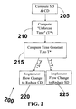
- FIG. 2 is a flow chart which lists a sequence of steps according to an embodiment of the invention that comprises a non-linear control algorithm which based on the differential parameters CD and SD and the relative speed of the flow disturbance, controls surge capacity for a vessel within a processing system.
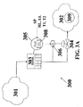
- FIG. 3A shows a depiction of an exemplary implementation of a non-linear level controller (NLLC) according to an embodiment of the invention for downstream surge control in a processing system having a surge vessel.
- NLLC non-linear level controller
- FIG. 3B shows a depiction of an exemplary implementation of a non-linear level controller (NLLC) according to an embodiment of the invention for upstream surge control in a processing system having a surge vessel.
- NLLC non-linear level controller
- FIG. 4 shows simulated results for a relatively fast disturbance that demonstrates performance for a NLLC controller according to an embodiment of the invention positioned in the processing system as shown in FIG. 3A for T* ⁇ T1.
- FIG. 5 shows simulated results for a relatively slow disturbance that demonstrates performance for NLLC controller according to an embodiment of the invention again positioned in the processing system as shown in FIG. 3A for T* > T1 for an outlet flow.
- a method for controlling surge capacity comprises the steps of providing a first vessel having a capacity and an inlet for receiving an inlet flow of a fluid comprising liquid subject to variation and an outlet for supplying an outlet flow of the fluid comprising liquid to at least one downstream unit.
- the downstream unit can include, for example, a distillation tower, a furnace, or another vessel, for example, a separator vessel.
- processing systems can include a plurality of vessels controlled by non-linear level controllers (NLLCs) according to the present invention, including serial and parallel connected vessel arrangements.
- the fluid comprising liquid can comprise liquid only, or a liquid mixed with a gas.
- the liquid itself can be a liquid mixture, such as oil and water.
- Conventional level sensors generally provide the liquid level measurement.
- the volume of liquid in the vessel is referred to herein in its common usage as the inventory and is generally measured in terms of the height of the liquid level.
- a discrepancy (difference) between a current inventory in the vessel and a prevailing inventory limit for the vessel (referred to herein as "capacity deviation” (CD)
- CD city deviation
- SD set point deviation
- Figure 1 depicts a vessel 100 having a liquid therein shown reaching the current level (the inventory) 103, and the parameters low level limit 101, setpoint 102 and high level limit 104.
- the desired level is shown as the setpoint 102.
- the operating capacity of the vessel 100 is specified in terms of a low level limit (shown as a low limit 101) and a high level limit (shown as a high limit 104), both beyond which operation is not desirable.
- Low limit 101, setpoint 102 and high level limit 104, together with the current level 103 define the differential parameters SD 105 and CD 106 used in an embodiment of the present invention.
- to keep the liquid level at the setpoint 102 would mean that the outlet flow will follow the fluctuations in the inlet flow.
- the current level 103 is above the setpoint 102. However, the current level 103 can also be at or below the setpoint 102.
- CD is a measure of discrepancy in the current level 103 and the prevailing limit, which is generally either the low limit 101 or the high limit 104.
- FIG. 1 shows the prevailing limit as being the high limit and thus CD defined by high limit 104, the prevailing limit can also be the low limit 101.
- the prevailing limit can be detected by the NLLC algorithm, generally based of the sign of the time derivative of the liquid level in the vessel. For example, if the level in the vessel is increasing, the sign of the derivative is positive, and the prevailing limit is generally the high limit 104. Conversely, if the level is decreasing, the sign of the derivative is negative, and the prevailing limit is generally the low limit 101. CD is thus measured in terms of the volume (available or excess) from the current level to generally reach the prevailing limit.
- SD Setpoint Deviation
- a first time (T1) to reduce CD by a first predetermined percentage (e.g. 100%/exhaust) and a second time (T2) to reduce SD by a second predetermined percentage (e.g. 100%/exhaust) is generally provided.
- Values for T1 and T2 are generally derived from empirical process tuning tests known in the art.
- an unforced time (referred to herein as T*) to reduce CD by the first percentage is calculated.
- T* is thus defined as the time to completely exhaust CD corresponding to a volume of the fluid comprising liquid if no changes to the flows are made by the controller (e.g. the status quo).
- the conditions for calculating the unforced time can be based on the most recent measurement of the current level 103 that is stored in memory associated with the NLLC, and/or the change in the current level 103 since the last execution of the NLLC algorithm.
- FIG. 2 is a flow chart which lists a sequence of steps according to an embodiment of the invention that comprises a non-linear control algorithm 200 which is based on the differential parameters CD and SD and the relative speed of the flow disturbance, which controls surge capacity for a vessel within a processing system.
- step 205 SD and CD as described above are calculated.
- step 210 T* as described above can be calculated, or otherwise provided (e.g. stored from an earlier computation).
- step 215 T* is then compared to a time constant T1. If T* ⁇ T1a first minimum change in the outlet flow from the vessel to reduce CD by the first predetermined percentage in T1 is computed and implemented as a flow change in step 220.
- T* ⁇ T1 generally corresponds to the variation/disturbance being relatively fast.
- a second minimum change in the outlet flow from the vessel to reduce (e.g. exhaust in one embodiment) SD to the second predetermined percentage in T2 is calculated and implemented as a flow change in step 225.
- the flow change can be implemented using a flow control parameter.
- the flow control parameter can be the actual fluid comprising liquid flow or a change in the fluid comprising liquid flow.
- NLLCs according to embodiments of the invention can control the output flow setpoint of a flow controller which is coupled to a control valve to implement the first minimum flow change (when T* ⁇ T1) or the second minimum flow change (T* > T1).
- FIG. 3A shows a depiction of an exemplary implementation of a non-linear level controller (NLLC) according to an embodiment of the invention for downstream surge control in a processing system 300 having a vessel 303.
- Reference 301 represents an upstream process that provides an outlet flow comprising a fluid comprising liquid flow that fluctuates significantly and may also be noisy.
- the outlet flow from the upstream process 301 is coupled to an inlet of a downstream process 302 via vessel 303.
- Downstream process 302 can be, for example, a distillation tower, a furnace, or a separator vessel comprising equipment 309, such as valves, pumps and motors.
- 305 refer to a NLLC according to an embodiment of the present invention.
- NLLC generally includes central processing unit (CPU) 308, as well as associated memory.
- NLLC 305 is operable to store or receive a plurality of inputs, such as setpoint (SP), high level (HL), low level (LL), and T1 and T2 described above, as well as current level (inventory) data from vessel 303.
- NLLC 305 generally executes on a control system computer and adjusts system flows including a flow of the fluid comprising liquid to downstream process 302 via a flow controller (FC) 306 which together with control valve 304 adjusts the outlet flow from vessel 303.
- FC flow controller
- FIG. 3B shows a depiction of an exemplary implementation of a non-linear level controller (NLLC) according to an embodiment of the invention for upstream surge control in a processing system 350 having a surge vessel 303.
- NLLC non-linear level controller
- the inlet flow to vessel 303 can be used to control the level in the vessel 303.
- Control in the upstream control case is generally achieved by multiplying the flow changes described relative to a downstream control system described above by -1.
- Embodiments of the present invention provide several significant advantages. Algorithms according to the invention are relatively simple, and are generally based on two calculated parameters, CD and SD. The algorithms are generally non-linear permitting good accuracy, particularly when the processes are significantly non-linear. Due to the simplicity of the executable code based on the few required parameters, the code can be run at high speed to allow frequent updates, such as on the order of several seconds.
- Surge vessels that can be level controlled by non-linear level controllers (NLLCs) according to embodiments of the present invention include, but are not limited to, Distillation Columns or Fractionator bottom sumps, Degassing Drums, Gas Separators, Storage Tanks, Feed Flash Drums, Reflux Accumulators, Day Tanks, Surge Drums, Suction Scrubbers, Slug Catchers, Lube Oil Separators, Head Tanks, and Deaerators.
- NLLCs non-linear level controllers
- NLLCs can be used in a variety of processing facilities that control fluid comprising liquid surge capacity, such as various manufacturing plants, as well as chemical plants and oil refineries, gas processing plants and offshore production platforms.
- FIG. 4 shows simulated results for a relatively fast disturbance that demonstrates NLLC performance for a controller according to an embodiment of the present invention positioned in the downstream controlled processing system as shown in FIG. 3A for T* ⁇ T1.
- the y-axis is the level in the vessel and the x-axis is time.
- FIG. 4 demonstrates that a high level of mitigation of inlet flow variation has been achieved by fully utilizing the available vessel capacity (allowing the level to reach the high level, HL, in a non-linear fashion, without any significant overshoot. Thereafter, the vessel level approached the desired level setpoint (SP), again in a non-linear fashion.
- SP desired level setpoint
- FIG. 5 shows a simulated result for a relatively slow disturbance that demonstrates NLLC performance for a controller according to an embodiment of the present invention again positioned in the downstream controlled processing system as shown in FIG. 3A , this time for T* > T1.
- FIG. 5 demonstrates that the inlet flow variation has been successfully mitigated by utilizing only some of the available vessel capacity as evidence by the current level never reaching the high level, HL. Thereafter, the vessel level returns back to the desired level setpoint shown as SP.
- the methods described herein are intended for operation as software programs running on a computer processor.
- software implementations can include, but not limited to, distributed processing or component/object distributed processing, parallel processing, or virtual machine processing can also be constructed to implement the methods described herein.
- the present disclosure contemplates a machine readable medium containing instructions, or that which receives and executes instructions from a propagated signal so that a device, such as connected to a network environment can send or receive data, and to communicate over the network using the instructions.
Landscapes
- Physics & Mathematics (AREA)
- General Physics & Mathematics (AREA)
- Engineering & Computer Science (AREA)
- Automation & Control Theory (AREA)
- Feedback Control In General (AREA)
- Flow Control (AREA)
Claims (12)
- Verfahren zum Steuern der Punktgrenzmenge in einem Verarbeitungssystem (300, 350), das mindestens ein Gefäß (303) umfasst, das einen Einlassstrom eines Fluids, das eine einer Variation unterliegende Flüssigkeit umfasst, empfängt und einen Auslassstrom zu mindestens einer nachgeschalteten Einheit (302) liefert, umfassend die folgenden Schritte:Berechnen eines ersten Parameters bezüglich einer Differenz zwischen einem aktuellen Bestand in dem Gefäß (303) und einer vorherrschenden Bestandsgrenze für das Gefäß (303) und eines zweiten Parameters bezüglich einer Differenz zwischen dem aktuellen Bestand und einem Bestandsollwert;Vergleichen einer ungezwungenen Zeit (T*), während der keine Änderungen an dem Einlass- oder Auslassstrom durch einen Controller vorgenommen werden, um den ersten Parameter um einen ersten Prozentsatz und eine erste Zeitkonstante T1 zu reduzieren, undSteuern des Einlassstroms oder des Auslassstroms auf der Basis des ersten Parameters, falls T* ≤ T1, und auf der Basis des zweiten Parameters, falls T* > T1.
- Verfahren nach Anspruch 1, weiterhin umfassend den Schritt des Berechnens der ungezwungenen Zeit (T*), um den ersten Parameter um den ersten Prozentsatz zu reduzieren.
- Verfahren nach Anspruch 2, wobei der Schritt des Berechnens der ungezwungenen Zeit (T*) eine Extrapolation unter Verwendung des aktuellen Bestands und eine zeitliche Ableitung des Bestands zu einer Zeit entsprechend dem aktuellen Bestand umfasst.
- Verfahren nach Anspruch 1, wobei der Steuerschritt das Berechnen einer ersten kleinsten Änderung in dem Einlass- oder Auslassstrom umfasst, um den ersten Parameter um den ersten Prozentsatz in der T1 zu reduzieren, falls T* ≤ T1, und das Berechnen einer zweiten kleinsten Änderung bei dem Einlass- oder dem Auslassstrom, um den zweiten Parameter um einen zweiten Prozentsatz in einer Zeit T2 zu reduzieren, falls T* > T1.
- Verfahren nach Anspruch 4, wobei der Steuerschritt das Steuern eines Stromparameters bezüglich des Einlassstroms oder des Auslassstroms auf der Basis der ersten kleinsten Änderung oder der zweiten kleinsten Änderung umfasst.
- Verfahren nach Anspruch 4, wobei der erste und zweite Prozentsatz 100% beträgt.
- Nichtlinearer Pegelcontroller (NLCC - Non-Linear Level Controller) (305) zum Steuern der Punktgrenzmenge in einem Verarbeitungssystem (300, 350), das mindestens ein Gefäß (303) umfasst, das einen Einlassstrom eines Fluids, das eine einer Variation unterliegende Flüssigkeit umfasst, empfängt und einen Auslassstrom zu mindestens einer nachgeschalteten Verarbeitungseinheit (302) liefert, umfassend:eine CPU (308), auf der gespeicherte ausführbare Software läuft, die die folgenden Schritte implementiert:Berechnen eines ersten Parameters bezüglich einer Differenz zwischen einem aktuellen Bestand in dem Gefäß (303) und einer vorherrschenden Bestandsgrenze für das Gefäß (303) und eines zweiten Parameters bezüglich einer Differenz zwischen dem aktuellen Bestand und einem Bestandsollwert;Vergleichen einer ungezwungenen Zeit (T*), während der keine Änderungen an dem Einlass- oder Auslassstrom durch einen Controller vorgenommen werden, um den ersten Parameter um einen ersten Prozentsatz und eine erste Zeitkonstante T1 zu reduzieren;mehrere an die CPU (308) gekoppelte Eingänge, die arbeiten können zum Empfangen von Prozessinformationen, die Informationen über das Fluid umfassen, das eine Flüssigkeit umfasst, während eines Prozesses, der durch das Verarbeitungssystem (300, 350) ausgeführt wird, undmehrere von der CPU (308) angesteuerte Ausgänge zum Senden von Steuersignalen zum Steuern des Einlassstroms oder des Auslassstroms auf der Basis des ersten Parameters, falls T* T1, und auf der Basis des zweiten Parameters, falls T* > T1.
- NLLC (305) nach Anspruch 7, wobei der NLLC (305) dahingehend arbeiten kann, die ungezwungene Zeit (T*) zu berechnen, um den ersten Parameter um den ersten Prozentsatz zu reduzieren.
- NLLC (305) nach Anspruch 7, wobei das Berechnen der ungezwungenen Zeit (T*) eine Extrapolation unter Verwendung des aktuellen Bestands und eine zeitliche Ableitung des Bestands zu einer Zeit entsprechend dem aktuellen Bestand umfasst.
- NLLC (305) nach Anspruch 7, wobei der NLLC (305) betrieben werden kann zum Berechnen einer ersten kleinsten Änderung in dem Einlass- oder Auslassstrom, um den ersten Parameter um den ersten Prozentsatz in T1 zu reduzieren, falls T* ≤ T1, und zum Berechnen einer zweiten kleinsten Änderung bei dem Einlass- oder dem Auslassstrom, um den zweiten Parameter um einen zweiten Prozentsatz in einer Zeit T2 zu reduzieren, falls T* > T1.
- Verarbeitungssystem (300, 350), das Folgendes umfasst:Gerät zum Durchführen von Aktionen zum Verarbeiten eines Fluids, das Flüssigkeiten umfasst, in dem Verarbeitungssystem (300, 350), wobei das System mindestens ein erstes Gefäß (303) umfasst, wobei das erste Gefäß (303) eine Kapazität und einen Einlass zum Aufnehmen eines Einlassstroms des eine Flüssigkeit umfassenden Fluids und einen Auslass zum Liefern eines Auslassstroms zu mindestens einer nachgeschalteten Einheit (302) aufweist, undeinen nichtlinearen Pegelcontroller (NLLC) (305) zum Steuern der Pumpgrenzmenge in dem System, an einen Strömungscontroller (306) gekoppelt, wobei der Strömungscontroller (306) an ein Steuerventil (304) gekoppelt ist, das arbeiten kann zum Steuern des Einlassstroms zu oder des Auslassstroms von dem Gefäß (303), wobei der NLLC (305) Folgendes umfasst:eine CPU (308), auf der gespeicherte ausführbare Software läuft, die die folgenden Schritte implementiert:Berechnen eines ersten Parameters bezüglich einer Differenz zwischen einem aktuellen Bestand in dem Gefäß (303) und einer vorherrschenden Bestandsgrenze für das Gefäß (303) und eines zweiten Parameters bezüglich einer Differenz zwischen dem aktuellen Bestand und einem Bestandsollwert; und Vergleichen einer ungezwungenen Zeit (T*), während der keine Änderungen an dem Einlass- oder Auslassstrom durch einen Controller vorgenommen werden, um den ersten Parameter um einen ersten Prozentsatz und eine erste Zeitkonstante T1 zu reduzieren;mehrere an die CPU (308) gekoppelte Eingänge, die arbeiten können zum Empfangen von Prozessinformationen, die Informationen über das Fluid umfassen, das eine Flüssigkeit umfasst, während eines Prozesses, der durch das Verarbeitungssystem (300, 350) ausgeführt wird, undmehrere von der CPU angesteuerte Ausgänge zum Senden von Steuersignalen zum Steuern des Einlassstroms oder des Auslassstroms auf der Basis des ersten Parameters, falls T* ≤ T1, und auf der Basis des zweiten Parameters, falls T* > T1.
- System nach Anspruch 11, wobei der NLLC (305) betrieben werden kann zum Berechnen einer ersten kleinsten Änderung in dem Einlass- oder Auslassstrom, um den ersten Parameter um den ersten Prozentsatz in T1 zu reduzieren, falls T* ≤ T1, und zum Berechnen einer zweiten kleinsten Änderung bei dem Einlass- oder dem Auslassstrom, um den zweiten Parameter um einen zweiten Prozentsatz in einer Zeit T2 zu reduzieren, falls T* > T1.
Applications Claiming Priority (2)
| Application Number | Priority Date | Filing Date | Title |
|---|---|---|---|
| US95108407P | 2007-07-20 | 2007-07-20 | |
| US11/859,432 US7684899B2 (en) | 2007-07-20 | 2007-09-21 | Process controller having improved surge capacity control and related methodology |
Publications (3)
| Publication Number | Publication Date |
|---|---|
| EP2017686A2 EP2017686A2 (de) | 2009-01-21 |
| EP2017686A3 EP2017686A3 (de) | 2009-11-04 |
| EP2017686B1 true EP2017686B1 (de) | 2013-02-27 |
Family
ID=39800688
Family Applications (1)
| Application Number | Title | Priority Date | Filing Date |
|---|---|---|---|
| EP20080160298 Ceased EP2017686B1 (de) | 2007-07-20 | 2008-07-11 | Prozessregler mit verbesserter Steuerung der Überschusskapazität und entsprechendes Verfahren |
Country Status (4)
| Country | Link |
|---|---|
| US (1) | US7684899B2 (de) |
| EP (1) | EP2017686B1 (de) |
| CN (1) | CN101561662B (de) |
| AU (1) | AU2008203149B2 (de) |
Families Citing this family (9)
| Publication number | Priority date | Publication date | Assignee | Title |
|---|---|---|---|---|
| GB2460301A (en) * | 2008-05-30 | 2009-12-02 | Pulsar Process Measurement Ltd | Sump monitoring method and apparatus |
| US8438430B2 (en) * | 2008-08-21 | 2013-05-07 | Vmware, Inc. | Resource management system and apparatus |
| US8449821B2 (en) * | 2010-05-25 | 2013-05-28 | Honeywell International Inc. | Slug mitigation by increasing available surge capacity |
| CN103135619A (zh) * | 2012-07-23 | 2013-06-05 | 周美荣 | 一种防液回流装置 |
| NL2013793B1 (en) * | 2014-11-13 | 2016-10-07 | Advanced Tech & Innovations B V | A continuous through-flow settling vessel, and a method of adaptive separation of a mixture from gas and/or oil exploration. |
| CN108062117B (zh) * | 2017-12-29 | 2021-03-02 | 国电科学技术研究院 | 一种多台除氧器并列运行水位控制装置 |
| US12188910B2 (en) | 2019-05-16 | 2025-01-07 | Wyatt Technology, Llc | Regulating a detector flow of a field flow fractionator |
| US11435209B2 (en) * | 2019-05-16 | 2022-09-06 | Wyatt Technology Corporation | Regulating a detector flow of a field flow fractionator |
| CN117251000B (zh) * | 2023-11-20 | 2024-02-09 | 武汉华信数据系统有限公司 | 液位控制方法、系统、设备及介质 |
Family Cites Families (15)
| Publication number | Priority date | Publication date | Assignee | Title |
|---|---|---|---|---|
| US4265263A (en) | 1979-08-28 | 1981-05-05 | Phillips Petroleum Company | Non-linear level controller |
| US4386623A (en) * | 1980-12-30 | 1983-06-07 | Phillips Petroleum Company | Nonlinear control of liquid level |
| JPS57199004A (en) * | 1981-06-01 | 1982-12-06 | Toshiba Corp | Sample value adaptive process controller |
| JPS58154003A (ja) * | 1982-03-05 | 1983-09-13 | Mitsubishi Electric Corp | 自動制御方法 |
| US4956763A (en) | 1988-07-29 | 1990-09-11 | Shell Oil Company | Portable self-contained surge level controller |
| US5335185A (en) * | 1992-04-24 | 1994-08-02 | Halliburton Company | Automatic level control system and method |
| US5396923A (en) * | 1992-10-28 | 1995-03-14 | Allen; Donald M. | Surge relief apparatus and method |
| DE4321604A1 (de) * | 1993-06-29 | 1995-01-19 | Siemens Ag | Regeleinrichtung, insbesondere für einen nichtlinearen, zeitvarianten Prozeß |
| WO2001059534A1 (en) * | 2000-02-11 | 2001-08-16 | Stone & Webster Process Technology, Inc. | Heat and material balance method of process control for petrochemical plants and oil refineries |
| US6622056B1 (en) * | 2000-11-17 | 2003-09-16 | Johan Lindell | Method and system for supply chain or supply network control |
| WO2003026791A1 (en) * | 2001-09-26 | 2003-04-03 | Bp Corporation North America Inc. | Integrated chemical process control |
| US7284563B2 (en) * | 2004-05-14 | 2007-10-23 | Spx Corporation | Surge relief apparatus and method |
| US20080103747A1 (en) * | 2006-10-31 | 2008-05-01 | Macharia Maina A | Model predictive control of a stillage sub-process in a biofuel production process |
| US8521310B2 (en) * | 2006-10-31 | 2013-08-27 | Rockwell Automation Technologies, Inc. | Integrated model predictive control of distillation and dehydration sub-processes in a biofuel production process |
| US7546170B2 (en) * | 2007-01-02 | 2009-06-09 | Neuroblast, Inc. | Easily tuned and robust control algorithm for single or multiple variable systems |
-
2007
- 2007-09-21 US US11/859,432 patent/US7684899B2/en not_active Expired - Fee Related
-
2008
- 2008-07-11 EP EP20080160298 patent/EP2017686B1/de not_active Ceased
- 2008-07-15 AU AU2008203149A patent/AU2008203149B2/en not_active Ceased
- 2008-07-18 CN CN2008102147664A patent/CN101561662B/zh not_active Expired - Fee Related
Also Published As
| Publication number | Publication date |
|---|---|
| US20090024253A1 (en) | 2009-01-22 |
| CN101561662A (zh) | 2009-10-21 |
| AU2008203149A1 (en) | 2009-02-05 |
| EP2017686A3 (de) | 2009-11-04 |
| AU2008203149B2 (en) | 2012-04-05 |
| CN101561662B (zh) | 2012-07-11 |
| EP2017686A2 (de) | 2009-01-21 |
| US7684899B2 (en) | 2010-03-23 |
Similar Documents
| Publication | Publication Date | Title |
|---|---|---|
| EP2017686B1 (de) | Prozessregler mit verbesserter Steuerung der Überschusskapazität und entsprechendes Verfahren | |
| DK1991758T3 (en) | METHOD AND FEEDBACK MANAGEMENT OR MONITORING OF OIL OR GAS SOURCE PRODUCTION SYSTEM AND COMPUTER PROGRAM PRODUCT THEREOF | |
| US8449821B2 (en) | Slug mitigation by increasing available surge capacity | |
| EP1389259B1 (de) | Verfahren zur verbesserung von produktionszuweisung in einem integrierten reservoir und oberflächenströmungssystem | |
| US4180083A (en) | System for controlling flow rate in pipelines | |
| AU2016370954B2 (en) | Deriving the gas volume fraction (GVF) of a multiphase flow from the motor parameters of a pump | |
| KR102189649B1 (ko) | 냉각탑 시스템의 동적 모니터링, 진단 및 제어 | |
| EP3992528B1 (de) | Verfahren zur steuerung der zufuhr von speisewasser in einen kessel | |
| WO2006014372A2 (en) | Pipeline flow control optimization software, and methods | |
| EP3289415B1 (de) | Formulierung von dauerzustandszielen mittels priorisierter zielfunktionen | |
| Ribeiro et al. | Model Predictive Control with quality requirements on petroleum production platforms | |
| TW202303305A (zh) | 管理系統、管理方法及管理程式 | |
| Matias et al. | Real-time optimization with persistent parameter adaptation applied to experimental rig | |
| Verheyleweghen et al. | Health-aware operation of a subsea gas compression system under uncertainty | |
| US20080091281A1 (en) | Method for the Monitoring and Control of a Process | |
| US11560698B2 (en) | State analysis device, state analysis method, and recording medium | |
| JP5115185B2 (ja) | プラント運転支援システム | |
| Mohammed et al. | Design of Fault Tolerant Control System (strategy) for Two Water Tanks | |
| JP4008449B2 (ja) | スケール付着程度の評価方法 | |
| Ims | Risk-based health-aware control of Åsgard subsea gas compression station. en | |
| Degner | Online Feedback Optimization for Gas Compressors | |
| JP3422009B2 (ja) | 計量給油装置用ポンプのファジィ調整システム | |
| CN114704232A (zh) | 油井群注水方法 |
Legal Events
| Date | Code | Title | Description |
|---|---|---|---|
| PUAI | Public reference made under article 153(3) epc to a published international application that has entered the european phase |
Free format text: ORIGINAL CODE: 0009012 |
|
| 17P | Request for examination filed |
Effective date: 20080711 |
|
| AK | Designated contracting states |
Kind code of ref document: A2 Designated state(s): AT BE BG CH CY CZ DE DK EE ES FI FR GB GR HR HU IE IS IT LI LT LU LV MC MT NL NO PL PT RO SE SI SK TR |
|
| AX | Request for extension of the european patent |
Extension state: AL BA MK RS |
|
| PUAL | Search report despatched |
Free format text: ORIGINAL CODE: 0009013 |
|
| AK | Designated contracting states |
Kind code of ref document: A3 Designated state(s): AT BE BG CH CY CZ DE DK EE ES FI FR GB GR HR HU IE IS IT LI LT LU LV MC MT NL NO PL PT RO SE SI SK TR |
|
| AX | Request for extension of the european patent |
Extension state: AL BA MK RS |
|
| 17Q | First examination report despatched |
Effective date: 20091021 |
|
| AKX | Designation fees paid |
Designated state(s): DE FR GB |
|
| GRAP | Despatch of communication of intention to grant a patent |
Free format text: ORIGINAL CODE: EPIDOSNIGR1 |
|
| GRAS | Grant fee paid |
Free format text: ORIGINAL CODE: EPIDOSNIGR3 |
|
| GRAA | (expected) grant |
Free format text: ORIGINAL CODE: 0009210 |
|
| AK | Designated contracting states |
Kind code of ref document: B1 Designated state(s): DE FR GB |
|
| REG | Reference to a national code |
Ref country code: GB Ref legal event code: FG4D |
|
| REG | Reference to a national code |
Ref country code: DE Ref legal event code: R096 Ref document number: 602008022442 Country of ref document: DE Effective date: 20130425 |
|
| PLBE | No opposition filed within time limit |
Free format text: ORIGINAL CODE: 0009261 |
|
| STAA | Information on the status of an ep patent application or granted ep patent |
Free format text: STATUS: NO OPPOSITION FILED WITHIN TIME LIMIT |
|
| 26N | No opposition filed |
Effective date: 20131128 |
|
| REG | Reference to a national code |
Ref country code: DE Ref legal event code: R097 Ref document number: 602008022442 Country of ref document: DE Effective date: 20131128 |
|
| REG | Reference to a national code |
Ref country code: FR Ref legal event code: PLFP Year of fee payment: 9 |
|
| REG | Reference to a national code |
Ref country code: FR Ref legal event code: PLFP Year of fee payment: 10 |
|
| REG | Reference to a national code |
Ref country code: FR Ref legal event code: PLFP Year of fee payment: 11 |
|
| PGFP | Annual fee paid to national office [announced via postgrant information from national office to epo] |
Ref country code: FR Payment date: 20180726 Year of fee payment: 11 |
|
| PGFP | Annual fee paid to national office [announced via postgrant information from national office to epo] |
Ref country code: GB Payment date: 20180731 Year of fee payment: 11 |
|
| GBPC | Gb: european patent ceased through non-payment of renewal fee |
Effective date: 20190711 |
|
| PG25 | Lapsed in a contracting state [announced via postgrant information from national office to epo] |
Ref country code: GB Free format text: LAPSE BECAUSE OF NON-PAYMENT OF DUE FEES Effective date: 20190711 |
|
| PG25 | Lapsed in a contracting state [announced via postgrant information from national office to epo] |
Ref country code: FR Free format text: LAPSE BECAUSE OF NON-PAYMENT OF DUE FEES Effective date: 20190731 |
|
| PGFP | Annual fee paid to national office [announced via postgrant information from national office to epo] |
Ref country code: DE Payment date: 20200729 Year of fee payment: 13 |
|
| REG | Reference to a national code |
Ref country code: DE Ref legal event code: R119 Ref document number: 602008022442 Country of ref document: DE |
|
| PG25 | Lapsed in a contracting state [announced via postgrant information from national office to epo] |
Ref country code: DE Free format text: LAPSE BECAUSE OF NON-PAYMENT OF DUE FEES Effective date: 20220201 |