EP2017598A1 - Sample introduction system - Google Patents
Sample introduction system Download PDFInfo
- Publication number
- EP2017598A1 EP2017598A1 EP07740596A EP07740596A EP2017598A1 EP 2017598 A1 EP2017598 A1 EP 2017598A1 EP 07740596 A EP07740596 A EP 07740596A EP 07740596 A EP07740596 A EP 07740596A EP 2017598 A1 EP2017598 A1 EP 2017598A1
- Authority
- EP
- European Patent Office
- Prior art keywords
- gas
- flow channel
- flow rate
- sample
- introducing
- Prior art date
- Legal status (The legal status is an assumption and is not a legal conclusion. Google has not performed a legal analysis and makes no representation as to the accuracy of the status listed.)
- Withdrawn
Links
Images


Classifications
-
- G—PHYSICS
- G01—MEASURING; TESTING
- G01N—INVESTIGATING OR ANALYSING MATERIALS BY DETERMINING THEIR CHEMICAL OR PHYSICAL PROPERTIES
- G01N21/00—Investigating or analysing materials by the use of optical means, i.e. using sub-millimetre waves, infrared, visible or ultraviolet light
- G01N21/62—Systems in which the material investigated is excited whereby it emits light or causes a change in wavelength of the incident light
- G01N21/71—Systems in which the material investigated is excited whereby it emits light or causes a change in wavelength of the incident light thermally excited
- G01N21/714—Sample nebulisers for flame burners or plasma burners
-
- G—PHYSICS
- G01—MEASURING; TESTING
- G01N—INVESTIGATING OR ANALYSING MATERIALS BY DETERMINING THEIR CHEMICAL OR PHYSICAL PROPERTIES
- G01N30/00—Investigating or analysing materials by separation into components using adsorption, absorption or similar phenomena or using ion-exchange, e.g. chromatography or field flow fractionation
- G01N30/02—Column chromatography
- G01N30/04—Preparation or injection of sample to be analysed
- G01N30/06—Preparation
- G01N30/14—Preparation by elimination of some components
-
- G—PHYSICS
- G01—MEASURING; TESTING
- G01N—INVESTIGATING OR ANALYSING MATERIALS BY DETERMINING THEIR CHEMICAL OR PHYSICAL PROPERTIES
- G01N30/00—Investigating or analysing materials by separation into components using adsorption, absorption or similar phenomena or using ion-exchange, e.g. chromatography or field flow fractionation
- G01N30/02—Column chromatography
- G01N30/26—Conditioning of the fluid carrier; Flow patterns
- G01N30/28—Control of physical parameters of the fluid carrier
- G01N30/32—Control of physical parameters of the fluid carrier of pressure or speed
- G01N2030/324—Control of physical parameters of the fluid carrier of pressure or speed speed, flow rate
Definitions
- the present invention relates to a sample introducing system for introducing an analytical sample into an analytical device.
- analysis of analytical samples such as fine particles contained in a sample gas and specific gas components has been performed with analytical devices using highly sensitive analytical methods such as a gas chromatography spectrometry (GC-MS), an inductively coupled plasma analysis method (ICP method), and a microwave induced plasma analysis method (MIP method).
- GC-MS gas chromatography spectrometry
- ICP method inductively coupled plasma analysis method
- MIP method microwave induced plasma analysis method
- the analysis is performed by generating high-temperature plasma by using argon gas, nitrogen gas, helium gas and the like as a plasma gas, introducing an analytical sample into the plasma, and detecting signal variations from the plasma.
- a pretreatment device In order to analyze accurately the analytical sample contained in such sample gas, a pretreatment device is necessary that performs the pretreatment of removing unnecessary components from the sample gas. For example, when a sample gas containing a gaseous analytical sample is used, moisture, impurity gas components and the like other than the analytical sample contained in the sample gas are required to be removed as unnecessary components. Further, when a solution in which an analytical sample is dissolved in a solvent is converted into droplets floating in a spraying gas with a sprayer or the like and the spraying gas is used as the sample gas, it is required to remove moisture, solvent vapor and the like contained in the sample gas as unnecessary components.
- a gas replacement device, a fine particle classification device, a drier or the like is used as the pretreatment device.
- a sample gas is generated by converting a solvent having an analytical sample dissolved therein into a mist with a sprayer, the sample gas is heated to separate droplets into solvent vapor and an analytical sample, the sample gas is introduced in a tubular sealed filter made from a porous material, and the solvent vapor is removed by diffusion to the outside of the sealed filter.
- a flow rate of gas containing an analytical sample introduced into an analytical device is changed correspondingly to the type or the like of elements constituting the analytical sample, in order to satisfy the optimum analytical conditions. For example, in a high-sensitivity analysis using plasma, in order to analyze a plurality of elements that are the objects of analysis and contained in the analytical sample, automatic tuning is performed to switch automatically the flow rate of gas introduced together with the analytical sample into the plasma. Further, in the mass analysis using the ionization action of plasma, the flow rate of gas introduced into plasma is automatically changed so as to prevent polyatomic ions having a mass number equal to that of the element that is an object of analysis from hindering the analysis.
- a flow rate of an untreated sample gas introduced into the pretreatment device has been conventionally changed in order to change the flow rate of gas introduced together with an analytical sample into an analytical device.
- the flow rate or pressure of the sample gas in the pretreatment device also changes; therefore, treatment conditions have to be changed according to this change.
- pressure fluctuations of gas occur in a gas flow channel between the pretreatment device and analytical device, and there is a risk that the seal is ruptured and contaminating substances contained in the ambient atmosphere penetrate into the analytical device.
- temperature variations or electron density variations are induced in plasma, stable plasma cannot be maintained, and there is a risk that high-sensitivity analysis is impeded.
- the sample introducing system in accordance with the present invention includes a pretreatment device that performs a pretreatment of removing unnecessary components from an untreated sample including an analytical sample; a connection gas flow channel that introduces a treated sample gas treated by the pretreatment device into an analytical device; a gas addition device that adds a carrier gas to the treated sample gas that flows toward the analytical device in the connection gas flow channel; and a pressure adjusting device that restricts pressure fluctuations of a gas including the analytical sample upstream of the gas addition device, wherein the gas addition device includes changing means for changing an addition flow rate of the carrier gas.
- the addition flow rate of the carrier gas to the treated sample gas flowing in the connection gas flow channel between the pretreatment device and the analytical device is changed by the gas addition device, and pressure fluctuations of the gas including the analytical sample are restricted by the pressure adjusting device upstream of the gas addition device.
- the flow rate of the gas introduced into the analytical device together with the analytical sample can be changed without changing the flow rate of the untreated sample gas introduced into the pretreatment device and without causing pressure fluctuations of the gas including the analytical sample in the pretreatment device.
- the pressure adjusting device has a seal gas flow channel and a communication flow channel;
- the seal gas flow channel has an inlet port connected to a supply source of a seal gas and an outlet port communicating with an ambient atmosphere or an atmosphere under a constant pressure; a zone between the inlet port and the outlet port of the seal gas flow channel communicates via the communication flow channel with a zone between the gas addition device and the pretreatment device in the connection gas flow channel; setting means for setting an introduction flow rate of the untreated sample gas to the pretreatment device is provided; and the introduction flow rate of the untreated sample gas is set to a constant value.
- the zone between the gas addition device and the pretreatment device in the connection gas flow channel communicates with the ambient atmosphere or an atmosphere under a constant pressure, and the introduction flow rate of the untreated sample gas to the pretreatment device becomes constant. Therefore, when the addition flow rate of the carrier gas is changed, pressure fluctuations of gas in the pretreatment device can be reliably prevented, without changing the flow rate of the untreated sample gas introduced in the pretreatment device. Further, sealing between the sample introducing system and the outside can be ensured with the seal gas flowing in the seal gas flow channel. Thus, pressure fluctuations of gas in the pretreatment device can be restricted and the pretreatment device can be sealed from the ambient environment, without using movable components.
- the sample introducing system in accordance with the present invention preferably includes an introducing flow channel for introducing the untreated sample gas into the pretreatment device; wherein the pressure adjusting device has a seal gas flow channel and a communication flow channel; the seal gas flow channel has an inlet port connected to a supply source of a seal gas and an outlet port communicating with an ambient atmosphere or an atmosphere under a constant pressure; a zone between the inlet port and the outlet port of the seal gas flow channel communicates via the communication flow channel with the introducing flow channel; setting means for setting an introduction flow rate of the untreated sample gas to the pretreatment device is provided; and the introduction flow rate of the untreated sample gas is set to a constant value.
- the introducing flow channel communicates with the ambient atmosphere or an atmosphere under a constant pressure, and the introduction flow rate of the untreated sample gas to the pretreatment device becomes constant. Therefore, when the addition flow rate of the carrier gas is changed, pressure fluctuations of gas in the pretreatment device can be reliably prevented without changing the flow rate of the untreated sample gas introduced in the pretreatment device. Further, sealing between the sample introducing system and the outside can be ensured with the seal gas flowing in the seal gas flow channel. Thus, pressure fluctuations of gas in the pretreatment device can be restricted and the pretreatment device can be sealed from the ambient environment, without using movable components.
- the sample introducing system in accordance with the present invention also preferably includes an introducing flow channel for introducing the untreated sample gas into the pretreatment device; wherein the pressure adjusting device has a discharge flow channel that branches off from the introducing flow channel; the discharge flow channel has an outlet port communicating with an ambient atmosphere or an atmosphere under a constant pressure; setting means for setting a supply flow rate of the untreated sample gas to the introducing flow channel, and setting means for setting an introduction flow rate of the untreated sample gas to the pretreatment device are provided; the introduction flow rate of the untreated sample gas is set to a constant value; and a set value of the supply flow rate of the untreated sample gas is larger than a set value of the introduction flow rate.
- the outlet port of the discharge flow channel communicates with the ambient atmosphere or an atmosphere under a constant pressure, and the introduction flow rate of the untreated sample gas to the pretreatment device becomes constant; therefore, pressure fluctuations of gas in the pretreatment device can be reliably prevented without changing the flow rate of the untreated sample gas introduced in the pretreatment device.
- the set value of the supply flow rate of the untreated sample gas to the introducing flow channel is larger than the set value of the introduction flow rate of the untreated sample gas to the pretreatment device, sealing between the sample introducing system and the outside can be ensured with the untreated sample gas flowing in the discharge flow channel.
- pressure fluctuations of gas in the pretreatment device can be restricted and the pretreatment device can be sealed from the ambient environment, without using movable components.
- the analytical sample is in the form of solid fine particles;
- the pretreatment device has a porous partition; and a gas replacement function is realized with the pretreatment device by which at least part of gas components of the untreated sample gas are replaced with the replacement gas via diffusion caused by a partial pressure difference at the porous partition, and the treated sample gas includes the replacement gas replacing at least part of gas components of the untreated sample gas.
- unnecessary components can be removed by replacing at least part of gas components in the untreated sample gas with the replacement gas.
- the flow rate of the untreated sample gas when the flow rate of the untreated sample gas is changed so that the gas replacement efficiency does not change correspondingly to the type of the analytical sample, the flow rate of gas introduced into the analytical device can be maintained at a value optimum for the analysis by changing the flow rate of the carrier gas correspondingly to the variations in the flow rate of the untreated sample gas.
- the gas replacement efficiency in the pretreatment device can be optimized and the flow rate of gas introduced into the analytical device can be optimized, particularly in a plasma analytical device, stable plasma can be maintained.
- the sample introducing system in accordance with the present invention preferably includes an introducing flow channel for introducing the untreated sample gas into the pretreatment device; wherein the pretreatment device has a first pipe and a second pipe, and the first pipe and the second pipe are separated by the porous partition; the first pipe has a first inlet port connected to the introducing flow channel, a first outlet port connected to the connection gas flow channel, and a first gas flow channel between the first inlet port and the first outlet port; the second pipe has a second inlet port connected to a supply source of a replacement gas, a second outlet port for causing a discharge gas that includes the untreated sample gas replacing the replacement gas to flow out, and a second gas flow channel between the second inlet port and the second outlet port; the diameter of pores of the porous partition is set so as to prevent substantially a gas movement via the porous partition caused by a difference between a gas pressure in the first gas flow channel and a gas pressure in the second gas flow channel; the pressure adjusting device has a branch flow channel that causes
- the pressure of the untreated sample gas supplied to the introducing flow channel is equal to the atmospheric pressure or a constant pressure, and the set value of the total suction flow rate of the untreated sample gas and discharge gas is larger than the set value of the supply flow rate of the replacement gas to the second pipe. Therefore, part of the untreated sample gas supplied to the introducing flow channel is reliably sucked in by the gas suction means via the branch flow channel. Further, because the gas discharge side of the gas suction means communicates with an ambient atmosphere or an atmosphere under a constant pressure, the pressure of the untreated sample gas in the vicinity of the first inlet port in the introducing flow channel can be almost equal to the atmospheric pressure or a constant pressure.
- the analytical device is preferably a plasma analytical device having a tube for introducing the treated sample gas, to which the carrier gas has been added, into plasma.
- the addition flow rate of the carrier gas to the treated sample gas varies, since the gas is throttled in the tube, the inner pressure of the connection gas flow channel tends to change.
- pressure fluctuations of the gas in the connection gas flow channel between the pretreatment device and the gas addition device are restricted by the pressure adjusting device, contaminating substances in the ambient environment or the like can be prevented from penetrating into the analytical device via a seal or the like of the connection portion between the pretreatment device and the connection gas flow channel, and the treated sample gas can be prevented from leaking to the outside.
- the gas addition device preferably has an aspirator that introduces the treated sample gas into the connection gas flow channel based on a pressure head decrease of the carrier gas introduced into the connection gas flow channel.
- the carrier gas can be added without providing a movable member or a power source in the connection gas flow channel.
- the predetermined amount of the untreated sample gas can be introduced into the pretreatment device without providing a movable member or a power source.
- a sample introducing system that has flexibility to adapt easily to a variety of analytical conditions without being affected by a flow rate of gas introduced into an analytical device, can introduce the analytical sample into the analytical device without loss, and is suitable for a simple and highly accurate high-sensitivity analysis.
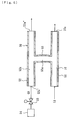
- a sample introducing system A1 of the first embodiment shown in Fig. 1 includes a pretreatment device 1 that performs a pretreatment of removing unnecessary components such as moisture, impurities, and solvent vapors from an untreated sample gas G1 including an analytical sample, and an introducing channel 10 for introducing the untreated sample gas G1 from a supply source into the pretreatment device 1.
- the analytical sample that is to be pretreated may be in an liquid or gas form.
- a sprayer 11 shown in Fig. 2 can be used as a supply source of the untreated sample gas G1.
- the sprayer 11 converts a solution 12 obtained by dissolving an analytical sample in a solvent into liquid droplets suspended in a spraying gas G2, removes the liquid droplets L with a large diameter, and supplies the remaining gas as a pressurized untreated sample gas G1 to the pretreatment device 1.
- a well-known sprayer can be used as such sprayer 11.
- a flow rate of the pressurized spraying gas G2 supplied from a pressure vessel such as a gas cylinder is controlled by a flow rate control device 13 such as a mass flow rate controller (MFC) or a flow rate control valve, and the flow rate control device 13 is used as setting means for setting the introduction flow rate of the untreated sample gas G1 to the pretreatment device 1.
- a flow rate control device 13 such as a mass flow rate controller (MFC) or a flow rate control valve
- a pressure vessel filled with a pressurized gas including a gaseous analytical sample as a supply source of the untreated sample gas G1
- provide a flow rate control device in this pipe as setting means for setting the introduction flow rate of the untreated sample gas G1 to the pretreatment device 1.
- the supply flow rate of the untreated sample gas G1 to the introducing flow channel 10 is taken as the introduction flow rate of the untreated sample gas G1 to the pretreatment device 1, and the introduction flow rate of the untreated sample gas G1 to the pretreatment device 1 is set to a constant value.
- the analytical sample of the present embodiment is in the form of solid fine particles.
- fine particles of the analytical sample contained in the untreated sample gas G1 are made, for example, from a metal such as iron powder, a metal compound such as an oxide or a sulfide, a ceramic, or an organic substance such as polymer compound.
- the pretreatment device 1 includes a porous partition 2A, and has a gas replacement function of replacing at least part of gas components in the untreated sample gas G1 with a replacement gas G3 by means of diffusion caused by the partial pressure difference at the porous partition 2A. As a result, unnecessary components such as solvent vapors contained in the untreated sample gas G1 can be removed.
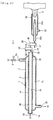
- the pretreatment device 1 has a double-tube structure that includes an inner tube 2 as a first pipe, which is a straight tube of an annular shape in a transverse section thereof, and an outer tube 3 as a second pipe, which is a straight tube of an annular shape in a transverse section thereof and covers the inner tube 2. Both ends of the inner tube 2 protrude to the outside from the outer tube 3, and portions of the outer tube close to both ends thereof are gradually reduced in diameter and joined to the outer periphery of the inner tube 2.
- the shapes of the inner and outer tubes 2, 3 are not particularly limited, for example, the tubes may be straight or curved.
- the inner tube 2 has an inner inlet portion 2a formed at one end as a first inlet port, an inner outlet port 2b formed at the other end as a first outlet port, and an inner gas flow channel 2c located between the inner inlet port 2a and inner outlet port 2b as a first gas flow channel.
- the outer tube 3 has an outer inlet port 3a as a second inlet port formed in a circumferential wall in the vicinity of one end to introduce the replacement gas G3, an outer outlet port 3b as a second outlet port formed in the circumferential wall in the vicinity of the other end, and an outer gas flow channel 3c as a second gas flow channel between the outer inlet port 3a and outer outlet port 3b.
- the outer inlet port 3a is connected to a supply source of the replacement gas G3.
- a pressure vessel filled with a pressurized replacement gas G3 is used as the supply source, and a flow rate control device 8 such as a mass flow rate controller (MFC) or a flow rate control valve is provided in the pipe connecting the pressure vessel to the outer inlet port 3a as setting means for setting the supply flow rate of the replacement gas G3 to the outer tube 3.
- MFC mass flow rate controller
- a flow rate control valve is provided in the pipe connecting the pressure vessel to the outer inlet port 3a as setting means for setting the supply flow rate of the replacement gas G3 to the outer tube 3.
- the inner inlet port 2a, inner outlet port 2b, outer inlet port 3a, and outer outlet port 3b are disposed so that the flow of the untreated sample gas G1 in the inner gas flow channel 2c and the flow of the replacement gas G3 in the outer gas flow channel 3c are in the mutually opposite directions.
- the inner tube 2, which is the first pipe, and the outer tube 3, which is the second pipe, are divided by the porous partition 2A.
- the section between the two ends of a circumferential wall that covers the inner gas flow channel 2c in the inner tube 2 is formed by the porous partition 2A, which serves to cause the untreated sample gas G1 to move to the outside of the inner gas flow channel 2c and also to cause the replacement gas G3 to move inside the inner gas flow channel 2c by the diffusion caused by the partial pressure difference between the untreated sample gas G1 and replacement gas G3.
- the diameter of pores in the porous partition 2A is set so as to prevent substantially the gas movement via the porous partition 2A caused by the difference between a gas pressure in the inner gas flow channel 2c and a gas pressure in the outer gas flow channel 3c, in the present embodiment, the diameter of pores is substantially 0.8 ⁇ m to 0.001 ⁇ m.
- the diameter of pores is set to a value equal to or larger than 0.001 ⁇ m, preferably equal to or larger than 0.002 ⁇ m, more preferably equal to or larger than 0.02 ⁇ m.
- the diameter of pores is set to a value equal to or less than 0.8 ⁇ m, preferably equal to or less than 0.5 ⁇ m, even more preferably equal to or less than 0.2 ⁇ m.
- the diameter of a very small number of pores, such that does not adversely affect the gas replacement function, in the porous partition 2A can be outside the range of 0.8 ⁇ m to 0.001 ⁇ m, but the range of 0.8 ⁇ m to 0.001 ⁇ m is substantially desirable.
- the porosity of the porous partition 2A is not particularly limited, but from the standpoint of gas replacement efficiency and mechanical strength, a range of 40% to 80% is preferred.
- the material of the porous partition 2A is not particularly limited provided that it is a porous material satisfying the above-described requirements, and glass such as quartz glass or ceramics is preferred, for example, Shirasu porous glass (SPG) can be used.
- SPG Shirasu porous glass
- the inner and outer diameter are equal to those of the porous partition 2A, thereby ensuring smooth joining.
- the entire circumferential wall covering the inner gas flow channel 2c may be formed by the porous partition, it is sufficient to form a section covering at least part of the inner gas flow channel 2c by the porous partition 2A.
- the materials of the sections 2B, 2C of the inner tube 2 close to both ends thereof and outer tube 3 are not particularly limited, and they may be formed by a plurality of different materials. For example, from the standpoint of processability, easiness of heating the untreated sample gas G1 introduced into the inner tube 2, and heat resistance, metals, ceramics, and glass are preferred, and ceramics or glass such as quartz glass is desirable.
- Gas replacement with the pretreatment device 1 is performed by introducing the untreated sample gas G1 including fine particles from the inner inlet port 2a into the inner tube 2, causing this gas to flow in the inner gas flow channel 2c surrounded by the porous partition 2A, introducing the replacement gas G3 from the outer inlet port 3a into the outer tube 3, and causing this gas to flow in the direction opposite to the flow direction of the untreated sample gas G1 in the outer gas flow channel 3c around the porous partition 2A.
- the concentration of replacement gas G3 gradually decreases and the concentration of untreated sample gas G1 gradually increases in the direction from the outer inlet port 3a to the outer outlet port 3b.
- the replacement gas G3 that has replaced at least part of gas components of the untreated sample gas G1 constitutes a treated sample gas G4 flowing out from the inner outlet port 2b together with the fine particles and a very small amount of the untreated sample gas G1.
- the untreated sample gas G1 and replacement gas G3 can be also caused to flow out as a discharge gas G5 from the outer outlet port 3b.
- the gas movement via the porous partition 2A caused by the difference in gas pressure between the inner gas flow channel 2c and outer gas flow channel 3c, that is, by the difference in gas pressure between the inside and the outside of the inner gas flow channel 2c, is substantially prevented by the porous partition 2A.
- the porous partition 2A by setting appropriately the pore diameter, porosity, thickness, tube diameter, length, and shape of the porous partition 2A, the inner diameter and shape of the outer tube 3, the flow rates of the untreated sample gas G1 and replacement gas G3, and the like, it is possible to decrease the amount of unnecessary components in the treated sample gas G4 flowing out of the inner outlet port 2b to an amount equal to or less than a critical amount that produces no adverse effect on the analysis in the analytical device.
- the amount of the untreated sample gas G1 moving to the outside of the inner gas flow channel 2c is almost equal to the amount of the replacement gas G3 moving into the inner gas flow channel 2c, practically all the untreated sample gas G1 in the inner gas flow channel 2c is replaced with the replacement gas G3, and fluctuations of the flow rate of the treated sample gas G4 flowing out from the inner outlet port 2b can be prevented.
- the fine particles with a diameter larger than the pore diameter of the porous partition 2A do not penetrate through the pores and are not trapped by the pores, the fine particles with a diameter equal to or less than the pore diameter have a diffusion rate lower than that of gas, and the inertia force created by the flow of diffusing gas is also very weak; therefore most of the fine particles flow out from the inner outlet port 2b together with the replacement gas G3 without moving into the outer gas flow channel 3c.
- the fine particles introduced together with the untreated sample gas G1 into the inner gas flow channel 2c can be supplied without loss into the analytical device together with the replacement gas G3 at a flow rate almost identical to that of the untreated sample gas G1.
- the treated sample gas G4 pretreated by the pretreatment device 1 flows out from the inner inlet port 2b into the connection gas flow channel 20, and is introduced into the analytical device 30 via the connection gas flow channel 20.
- the analytical device 30 of the present embodiment is a plasma analytical device.
- the analytical device 30 has a plasma torch 30a for forming plasma P by using argon gas, nitrogen gas, helium gas or the like as a plasma gas G6, and a center tube 30b disposed in the center of the plasma torch 30a for introducing the treated sample gas G4 into the plasma P.
- a well-known plasma analytical device can be used.
- the spraying gas G2 and replacement gas G3 preferably have the same composition as the plasma gas G6.
- connection gas flow channel 20 passes through inside the gas addition device 40 and pressure adjusting device 50.
- the gas addition device 40 adds a carrier gas G7 to the treated sample gas G4 flowing toward the analytical device 30 in the connection gas flow channel 20, and has means for changing the addition flow rate of the carrier gas G7.
- the gas addition device 40 of the present embodiment has an aspirator that introduces the treated sample gas G4 into the connection gas flow channel 20 based on a pressure head drop of the carrier gas G7 introduced into the connection gas flow channel 20.
- the gas addition device 40 has a first duct 41, a second duct 42 connected to the first duct 41, and a flow rate control device 43 such as a mass flow rate controller (MFC) or a flow rate control valve as means for changing the addition flow rate of the carrier gas G7.
- the ducts 41 and 42 constitute part of the connection gas flow channel 20.
- An opening at one end of the first duct 41 constitutes a gas outflow port 20b of the connection gas flow channel 20, and is connected to an inlet port of the center tube 30b of the analytical device 30.
- a throttle portion 41a and a diffuser 41b connected to an outlet port of the throttle portion 41a are formed in the first duct 41.
- An opening at the other end of the first duct 41 is connected via the flow rate control device 43 to a supply source 44 of the carrier gas G7.
- An inlet port of the second duct 42 communicates with the inner outlet port 2b of the pretreatment device 1 via a first pipe 51 of an after-mentioned pressure adjusting device 50, and an outlet port of the second duct 42 communicates with an ejection region of the carrier gas G7 in the vicinity of the outlet port of the throttle portion 41a.
- the supply source 44 is, for example, a pressure vessel such as a gas cylinder, and supplies the pressurized carrier gas G7 to the first duct 41.
- the treated sample gas G4 is sucked into the connection gas flow channel 20 based on the pressure head drop caused by the ejection of the carrier gas G7, which is introduced into the connection gas flow channel 20, from the throttle portion 41a, and the carrier gas G7 is added to the treated sample gas G4.
- the gas addition device 40 constitutes the aspirator. A well-known one can be used as this aspirator.
- the addition flow rate of the carrier gas G7 is changed by the flow rate control device 43.
- the treated sample gas G4 to which the carrier gas G7 has been added is introduced into the plasma P via the center tube 30b of the analytical device 30.
- the carrier gas G7 preferably has the same composition as the plasma gas G6.
- the pressure adjusting device 50 restricts pressure fluctuations of the gas including the analytical sample upstream of the gas addition device 40.
- the pressure adjusting device 50 of the present embodiment restricts the pressure fluctuations of the gas in the connection gas flow channel 20 between the pretreatment device 1 and the gas addition device 40.
- the pressure adjusting device 50 of the present embodiment has a first pipe 51 constituting the connection gas flow channel 20, a second pipe 52 constituting a seal gas flow channel 52a, and a joining pipe 53 that joins the first pipe 51 to the second pipe 52, and the inside of the joining pipe 53 serves as a communication flow channel 53a.
- An opening at one end of the first pipe 51 constitutes a gas inflow port 20a of the connection gas flow channel 20, and is connected to the inner outlet port 2b of the pretreatment device 1.
- An opening at the other end of the first pipe 51 is connected to the inlet port of the second duct 42 of the gas addition device 40.
- the treated sample gas G4 flowing out from the pretreatment device 1 is introduced into the center tube 30b of the analytical device 30 via the connection gas flow channel 20.
- An inlet port 52a' of the seal gas flow channel 52a is connected to a supply source 54 of the seal gas G8 via a flow rate control device 55 such as a mass flow rate controller (MFC) or flow rate control valve, and an outlet port 52a" of the seal gas flow channel 52a communicates with the atmosphere.
- MFC mass flow rate controller
- the outlet port 52a" of the seal gas flow channel 52a may communicate with an atmosphere under a constant pressure.
- a zone between the inlet port 52a' and outlet port 52a" in the seal gas flow channel 52a communicates via the communication flow channel 53a with a zone between the gas addition device 40 and pretreatment device 1 in the connection gas flow channel 20.
- connection gas flow channel 20 upstream of the gas addition device 40 drops due, for example, to suction of the treated sample gas G4 caused by the gas addition device 40
- part of the seal gas G8 introduced into the seal gas flow channel 52a from the inlet port 52a' is introduced into the connection gas flow channel 20, so that this pressure drop is canceled.
- the inside of the connection gas flow channel 20 is maintained under an almost atmospheric pressure between the pretreatment device 1 and the gas addition device 40. Therefore, when the addition flow rate of the carrier gas G7 changes, pressure fluctuations of gas in the pretreatment device 1 can be restricted by restricting pressure fluctuations of gas in the connection gas flow channel 20 between the pretreatment device 1 and the gas addition device 40.
- the seal gas G8 preferably has the same composition as the plasma gas G6. It is desirable that the flow rate of the seal gas G8 is set to a predetermined sufficient flow rate such that causes no fracture of the gas seal between the sample introducing system A1 and the outside.
- the addition flow rate of the carrier gas G7 to the treated sample gas G4 flowing in the connection gas flow channel 20 is changed by the gas addition device 40, and pressure fluctuations of gas in the pretreatment region are restricted by the pressure adjusting device 50.
- the flow rate of gas introduced together with the analytical sample into the analytical device 30 can be varied without changing the flow rate of the untreated sample gas G1 introduced into the pretreatment device 1 and without generating pressure fluctuations of the gas in the pretreatment device 1. Therefore, it is not necessary to change the treatment conditions in the pretreatment device 1 and it can be adapted to a variety of analytical conditions.
- connection gas flow channel 20 between the pretreatment device 1 and gas addition device 40 communicates with the ambient atmosphere or an atmosphere under a constant pressure via the seal gas flow channel 52a, and the introduction flow rate of the untreated sample gas G1 introduced into the pretreatment device 1 becomes constant.
- the addition flow rate of the carrier gas G7 is varied, pressure fluctuations of gas in the pretreatment device 1 can be reliably prevented without changing the flow rate of the untreated sample gas G1 introduced into the pretreatment device 1.
- a uniform pressure inside the connection gas flow channel 20 between the pretreatment device 1 and the gas addition device 40 can be maintained at a constant level.
- a gas seal between the sample introducing system A1 and the outside can be provided by the seal gas G8 flowing in the seal gas flow channel 52a.
- pressure fluctuations in the connection gas flow channel 20 can be restricted without using a movable member, and contamination in the system can be prevented by sealing the inside of the connection gas flow channel 20 from the ambient environment.
- contaminating substances present in the ambient environment and the like can be prevented from penetrating into the analytical device 30 via a seal or the like at the connection portion of the pretreatment device 1 and the connection gas flow channel 20, and the treated sample gas G4 can be prevented from leaking to the outside. Therefore, stable analysis results can be obtained, particularly in a plasma analytical device 30, stable plasma P can be maintained without causing temperature variations or electron density variations in the plasma P, thereby contributing to high-sensitivity analysis.
- the pretreatment device 1 unnecessary components can be removed by replacing at least some gas components in the untreated sample gas G1 with the replacement gas G3.
- the flow rate of the untreated sample gas G1 introduced into the pretreatment device 1 and gas pressure in the pretreatment device 1 do not fluctuate, it is not necessary to change the treatment conditions such as the flow rate and pressure of the replacement gas G3, and it can be easily adapted to the variations in the flow rate of gas introduced into the analytical device 30.
- gas replacement can be performed in the pretreatment device 1 regardless of the flow rate of gas introduced into the analytical device 30, dissipation of fine particles that are the analytical sample during gas replacement can be prevented and a constant gas replacement efficiency can be maintained.
- the flow rate of the untreated sample gas G1 is changed so that the gas replacement efficiency does not change correspondingly to the type of the analytical sample
- the flow rate of gas introduced into the analytical device 30 can be maintained at a value optimum for the analysis by changing the flow rate of the carrier gas G7 correspondingly to the variations in the flow rate of the untreated sample gas G1.
- the gas replacement efficiency in the pretreatment device 1 can be optimized, at the same time, the flow rate of gas introduced into the analytical device 30 can be optimized to maintain stable plasma P.
- the gas is throttled in the center tube 30b; therefore, if the pretreatment device 1 and analytical device 30 are directly connected, the pressure inside the connection gas flow channel 20 fluctuates due to variations in the flow rate of the gas introduced into the center tube 30b.
- the pretreatment device 1 and analytical device 30 are connected via the gas addition device 40, the flow rate of the gas introduced into the center tube 30b is changed by the gas addition device 40, and pressure fluctuations of gas in the connection gas flow channel 20 between the pretreatment device 1 and the gas addition device 40 are restricted by the pressure adjusting device 50 when the flow rate of the introduced gas is changed; therefore, contaminating substances in the ambient environment or the like can be prevented from penetrating into the system via the seal or the like of the connection portion between the pretreatment device 1 and the connection gas flow channel 20, and the treated sample gas G4 can be prevented from leaking to the outside.
- the inner diameter of the tip portion of the center tube 30b is 1 to 2 mm and the flow rate of gas introduced into the plasma P is 500 to 2000 ml/min
- the pressure inside the inner tube 2 of the pretreatment device 1 becomes several hundreds Pa; therefore, the analytical sample has to be prevented from dissipating to the outside of the system via the porous partition 2A.
- pressure fluctuations in the inner tube 2 can be prevented by the pressure adjusting device 50; therefore, such control of gas pressure in the inner tube 3 is unnecessary.
- the analytical conditions can be easily optimized by automatic tuning by which the flow rate of gas introduced into the plasma P is automatically switched correspondingly to the type of elements constituting the analytical sample.
- the gas addition device 40 By using an aspirator as the gas addition device 40, it is possible to add the carrier gas G7 without providing a movable member or a power source in the connection gas flow channel 20. Further, even when the untreated sample gas G1 itself does not have a pressure necessary to introduce the untreated sample gas into the pretreatment device 1, the predetermined amount of the untreated sample gas G1 can be introduced into the pretreatment device 1 without providing a movable member or a power source.
- the capability of the aspirator is not particularly limited, but it is preferred that the flow rate of the treated sample gas G4 that is sucked in is equal to or higher than the flow rate of the carrier gas G7.
- the flow rate of the carrier gas G7 is 500 ml/min
- the flow rate of the treated sample gas G4 that is sucked in is made equal to or higher than 500 ml/min.
- Any material can be used to make the aspirator, provided that it causes no problems such as contamination inside the system or selective adsorption of specific components, for example, quartz glass or Tygon (trade name of Norton Performance Plastics corporation: polyvinyl chloride) can be used.
- Figs. 4 to 6 illustrate the sample introducing system A2 of the second embodiment of the present invention.
- components identical to those of the first embodiment are assigned with identical reference symbols and only the differences between the two embodiments are explained.
- the pressure adjusting device 50 is disposed upstream of the pretreatment device 1, and the zone between the inlet port 52a' and the outlet port 52a" in the seal gas flow channel 52a is not communicate with the connection gas flow channel 20 but with the introducing flow channel 10 via the communication flow channel 53a.
- the inlet port of the second duct 42 in the gas addition device 40 of the second embodiment is directly connected to the inner outlet port 2b of the pretreatment device 1.
- An opening at one end of the fist pipe 51 in the pressure adjusting device 50 constitutes the gas outflow port 10a of the introducing flow channel 10 and is connected to the inner inlet port 2a of the pretreatment device 1.
- An opening at the other end of the first pipe 51 is connected to the supply source of the untreated sample gas G1 via a pipe constituting the introducing flow channel 10.
- the zone between the inlet port 52a' and the outlet port 52a" in the seal gas flow channel 52a communicates via the communication flow channel 53a with the vicinity of the inner inlet port 2a of the pretreatment device 1 in the introducing flow channel 10.
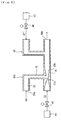
- Figs. 7 , 8 illustrate a sample introducing system A3 of the third embodiment of the present invention.
- components identical to those of the first embodiment are assigned with identical reference symbols and only the differences between the two embodiments are explained.
- the pressure adjusting device 50B is disposed upstream of the pretreatment device 1, and prevents gas pressure fluctuations without using the seal gas.
- the pressure adjusting device 50B of the third embodiment has a discharge flow channel 50' that branches off from the introducing flow channel 10 instead of the configuration of the pressure adjusting device 50 in the first embodiment.
- the discharge flow channel 50' and introducing flow channel 10 are formed by a T-shaped pipe.
- Part of the pressurized untreated sample gas G1 supplied to the introducing flow channel 10 in the same manner as in the first embodiment is introduced into the pretreatment device 1, and the remaining untreated sample gas is discharged from an outlet port 50" of the discharge flow channel 50'.
- the outlet port 50" of the discharge flow channel 50' communicates with the ambient atmosphere.
- the outlet port 50" of the discharge flow channel 50' may communicate with an atmosphere under a constant pressure.
- the inlet port of the second duct 42 in the gas addition device 40A of the third embodiment is directly connected to the inner outlet port 2b of the pretreatment device 1.
- the gas addition device 40A of the third embodiment has a third duct 45 and a flow rate control device 46 in addition to the configuration identical to the gas addition device 40 of the first embodiment.
- An opening at one end of the third duct 45 is connected to the inside of the first duct 41 downstream of the diffuser 41b, and an opening at the other end of the third duct 45 is connected to a supply source 47 of a carrier gas G7' via the flow rate control device 46.
- the supply source 47 can be, for example, a pressure vessel such as a gas cylinder, and it supplies the pressurized carrier gas G7' via the third duct 45 to the first duct 41.
- the carrier gas G7' preferably has the same composition as the plasma gas G6.
- the suction flow rate of the untreated sample gas G1 sucked by the aspirator constituted by the gas addition device 40A is taken as the introduction flow rate of the untreated sample gas G1 to the pretreatment device 1. Because this suction flow rate is determined correspondingly to the flow rate of the carrier gas G7 that is set by the flow rate control device 43, the flow rate control device 43 functions as means for setting the introduction flow rate of the untreated sample gas G1 to the pretreatment device 1. The introduction flow rate of the untreated sample gas G1 to the pretreatment device 1 is set to a constant value.
- the pressurized untreated sample gas G1 is supplied to the introducing flow channel 10 in the same manner as in the first embodiment, and means for setting the supply flow rate of the untreated sample gas G1 to the introducing flow channel 10 is provided.
- the flow rate control device 13 that sets the flow rate of the spraying gas G2 functions as means for setting the supply flow rate of the untreated sample gas G1.
- a pressure vessel serving as the supply source filled with a pressurized gas including a gaseous analytical sample as the untreated sample gas G1
- the set value of the supply flow rate of the untreated sample gas G1 to the introducing flow channel 10 is larger than the set value of the introduction flow rate of the untreated sample gas G1 to the pretreatment device 1.
- Other aspects in this embodiment are identical to those of the first embodiment.
- the outlet port of the discharge flow channel 50' communicates with the ambient atmosphere or an atmosphere under a constant pressure, and the introduction flow rate of the untreated sample gas G1 introduced into the pretreatment device 1 is constant, therefore pressure fluctuations of gas in the pretreatment device 1 can be reliably prevented without changing the flow rate of the untreated sample gas G1 introduced into the pretreatment device 1.
- the set value of the supply flow rate of the untreated sample gas G1 to the introducing flow channel 10 is larger than the set value of the introduction flow rate of the untreated sample gas G1 to the pretreatment device 1, a gas seal between the sample introducing system A3 and the outside can be ensured by the untreated sample gas G1 flowing in the discharge flow channel 50'.
- pressure fluctuations of gas in the pretreatment device 1 can be restricted and sealing from the ambient environment can be provided without using a movable member.
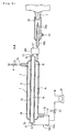
- Fig. 9 illustrates a sample introducing system A4 of the fourth embodiment of the present invention.
- components identical to those of the first embodiment are assigned with identical reference symbols and only the differences between the two embodiments are explained.
- the pressure of the untreated sample gas G1 supplied to the introducing flow channel 10 is the atmospheric pressure or a constant pressure
- the inlet port of the introducing flow channel 10 directly communicates with the atmosphere of the untreated sample gas G1 without any flow rate control device such as a mass flow rate controller (MFC) or a flow rate control valve.
- MFC mass flow rate controller
- the inlet port of the introducing flow channel 10 communicates with the ambient atmosphere or an atmosphere under a constant pressure, and the ambient atmosphere or the atmosphere under a constant pressure is taken as the untreated sample gas G1.
- the pressure adjusting device 50C is disposed upstream of the pretreatment device 1, and pressure fluctuations of gas are prevented without using a seal gas.
- the pressure adjusting device 50C of the fourth embodiment has a branch flow channel 50a that branches off from the introducing flow channel 10 instead of the configuration of the pressure adjusting device 50 in the first embodiment.
- One end of a pipe constituting the branch flow channel 50a is connected to a pipe constituting the introducing flow channel 10 in the vicinity of the inner inlet port 2a of the pretreatment device 1, and the other end of the pipe constituting the branch flow channel 50a is connected to the outer outlet port 3b of the pretreatment device 1.
- the branch flow channel 50a causes the introducing flow channel 10 to communicate with the outer outlet port 3b in the vicinity of the inner inlet port 2a.
- Gas suction means is provided for sucking part of the untreated sample gas G1 supplied to the introducing flow channel 10 together with the discharge gas G5 from the outer outlet port 3b of the pretreatment device 1 via the branch flow channel 50a.
- the gas suction means of the present embodiment is constituted by a vacuum pump 60, and a gas suction side of the vacuum pump 60 is connected via a flow rate control device 61 to the pipe constituting the branch flow channel 50a.
- a gas discharge side of the vacuum pump 60 communicates with the ambient atmosphere.
- the gas suction means is not limited to the vacuum pump 60 and may be constituted, for example, by a blower or a fan. Further, the gas discharge side of the vacuum pump 60 may communicate with an atmosphere under a constant pressure.
- the flow rate control device 61 constitutes means for setting a total suction flow rate of the untreated sample gas G1 and discharge gas G5 that are sucked by the vacuum pump 60.
- a set value of the total suction flow rate of the untreated sample gas G1 and discharge gas G5 that are sucked by the vacuum pump 60 is larger than a set value of the supply flow rate of the replacement gas G3 to the outer tube 3 that is set by the flow rate control device 8.
- the gas addition device 40A identical to that of the third embodiment is provided instead of the gas addition device 40 of the first embodiment, and the flow rate control device 46 acts as means for changing the addition flow rate of the carrier gas G7' added by the gas addition device 40A.
- the suction flow rate of the untreated sample gas G1 sucked by the aspirator constituted by the gas addition device 40A is taken as the introduction flow rate of the untreated sample gas G1 to the pretreatment device 1.
- This suction flow rate is determined according to the flow rate of the carrier gas G7 set by the flow rate control device 43, therefore the flow rate control device 43 functions as means for setting the introduction flow rate of the untreated sample gas G1 to the pretreatment device 1.
- the introduction flow rate of the untreated sample gas G1 to the pretreatment device 1 is set to a constant value.
- Other aspects in this embodiment are identical to those of the first embodiment.
- the pressure of the untreated sample gas G1 supplied to the introducing flow channel 10 is equal to the atmospheric pressure or a constant pressure, and the set value of the total suction flow rate of the untreated sample gas G1 and discharge gas G5 is larger than the set value of the supply flow rate of the replacement gas G3 to the outer tube 3.
- part of the untreated sample gas G1 supplied to the introducing flow channel 10 is reliably sucked by the vacuum pump 60 via the branch flow channel 50a.
- the gas discharge side of the vacuum pump 60 communicates with the ambient atmosphere or an atmosphere under a constant pressure, therefore the pressure of the untreated sample gas G1 in the vicinity of the inner inlet port 2a in the introducing flow channel 10 can be almost equal to the atmospheric pressure or a constant pressure.
- the pressure adjusting device may be configured by a pressure adjusting valve.
- the gas addition device may have constitution in which the treated sample gas is sucked by gas suction means such as a pump, a blower, or a fan instead of the aspirator, and the carrier gas discharged from a high-pressure cylinder or pump via a flow rate control device such as a mass flow rate controller (MFC) or a flow rate control valve is added to the treated sample gas in a connection gas flow channel downstream of the gas suction means.
- gas suction means such as a pump, a blower, or a fan instead of the aspirator
- the carrier gas G7' can be added to the treated sample gas G4 from the supply source 47 via the flow rate control device 46, therefore the gas addition device 40A may have gas suction means such as a pump, a blower, or a fan that sucks the untreated sample gas G1 instead of the aspirator.
- the inner tube 2 serves as a first pipe and the outer tube 3 serves as a second pipe, but the inner tube 2 may serve as the second pipe and the outer tube 3 may serve as the first pipe.
- the inner inlet port 2a serves as the second inlet port
- the inner outlet port 2b serves as the second outlet port
- the inner gas flow channel 2c serves as the second gas flow channel
- the outer inlet port 3a serves as the first inlet port
- the outer outlet port 3b serves as the first outlet port
- the outer gas flow channel 3c serves as the first gas flow channel
- the inner inlet port 2a is connected to the supply source of the replacement gas G3, the untreated sample gas G1 and replacement gas G3 flow out as the discharge gas G5 from the inner outlet port 2b, the untreated sample gas G1 is introduced into the outer gas flow channel 3c by connecting the introducing flow channel 10 to the outer inlet port 3a, and the treated sample gas G4 is introduced into the analytical device 30 via the connection gas flow channel 20 connected to the outer outlet port 3b.
- the pretreatment device 1 of the above-described embodiments has a double-tube structure in which the inner tube 2 serves as the first pipe and the outer tube 3 serves as the second pipe, but instead of this structure, a modification example shown in Fig.
- the analytical device is not limited to the plasma analytical device, for example, an analytical device that performs analysis by a gas chromatography mass spectrometry may be employed.
- a method for removing the unnecessary components with the pretreatment device is not limited to the above-described embodiments, for example, it is possible to use a drier that removes moisture as an unnecessary component, or a fine particle classification device in which gaseous contaminating components are removed when fine particles serving as an analytical sample are electrically charged and classified, and the fine particles are suspended in an atmosphere composed of desired gas species, as described in the section of the description relating to prior art.
- the sample introducing system A1 of the first embodiment was used, the flow rate of gas introduced into the center tube 30b of the analytical device 30 was changed, and the gas flow rate in the center tube 30b and gas pressure in the inner outlet port 2b of the pretreatment device 1 were measured.
- the flow rate of the untreated sample gas G1 was constant (300 ml/min), and the flow rate of gas introduced into the center tube 30b of the analytical device 30 was changed by changing the flow rate of the carrier gas G7.
- the inner diameter of the tip portion of the center tube 30b of the analytical device 30 was 1.5 mm.
- the gas pressure in the outer outlet port 3b of the pretreatment device, 1, outlet port 52a" of the sealed gas flow channel 52a, and outlet port of the center tube 30b was atmospheric pressure.
- the gas pressure in the inner outlet port 2b of the pretreatment device 1 was measured in the same manner as in Example 1, except that the inner diameter of the tip portion of the center tube 30b was 1.8 mm.
- a sample introducing system B of a comparative example shown in Fig. 11 was used instead of the sample introducing system A1 of the first embodiment, the flow rate of gas introduced into the center tube 30b of the analytical device 30 was changed, and the gas pressure in the inner outlet port 2b of the pretreatment device 1 was measured.
- the sample introducing system B of the comparative example had a configuration identical to that of the sample introducing system A1 of the embodiment, except that the gas addition device 40 and pressure adjusting device 50 were removed and the pretreatment device 1 and analytical device 30 were directly connected via the connection gas flow channel 20; components identical to those of the sample introducing system A1 of the embodiment are assigned with identical symbols.
- the flow rate of the untreated sample gas G1 was changed in the same manner as the flow rate of gas introduced into the center tube 30b of the analytical device 30 in Example 1.
- the inner diameter of the tip portion of the center tube 30b of the analytical device 30 was 1.5 mm.
- the gas pressure in the outer outlet port 3b of the pretreatment device 1 and the outlet port of the center tube 30b was atmospheric pressure.
- the gas pressure in the inner outlet port 2b of the pretreatment device 1 was measured in the same manner as in Comparative Example 1, except that the inner diameter of the tip portion of the center tube 30b was 1.8 mm.
- Table 1 The measurement results obtained in the examples are shown in Table 1 below.
- the measurement results obtained in the comparative examples are shown in Table 2.
- Table 1 Flow rate of untreated sample gas (ml/min) 300 300 300 300 300 300 300 300 300 300 300 300 300 300 300 Flow rate of carrier gas (ml/min) 450 500 550 600 650 700 750 Flow rate of gas in center tube (ml/min) 770 876 985 1098 1213 1328 1444 Pressure in inner outlet port (Pa)
- Example 1 3 3 3 3 2 2 2 Example 2 3 3 3 2 2 2 2 2
- Table 2 Flow rate of untreated sample gas (ml/min) 770 876 985 1098 1213 1328 1444 Pressure in inner outlet port (Pa) Comparative Example 1 104 127 160 201 244 288 328 Comparative Example 2 91 107 132 165 196 227 257
Abstract
Description
- The present invention relates to a sample introducing system for introducing an analytical sample into an analytical device.
- In recent years, concern about quality of living and working environment is risen, so that advanced analytical methods for measuring the composition and concentration of fine particles present in the atmosphere are sought. Further, in industries such as a semiconductor industry in which increased purity of material gases and atmosphere gas control in the manufacturing process are required, it is required to perform highly accurate analysis of the material gases containing fine particles and atmosphere gases in a simple manner.
- Accordingly, analysis of analytical samples such as fine particles contained in a sample gas and specific gas components has been performed with analytical devices using highly sensitive analytical methods such as a gas chromatography spectrometry (GC-MS), an inductively coupled plasma analysis method (ICP method), and a microwave induced plasma analysis method (MIP method). For example, in the ICP method and MIP method, the analysis is performed by generating high-temperature plasma by using argon gas, nitrogen gas, helium gas and the like as a plasma gas, introducing an analytical sample into the plasma, and detecting signal variations from the plasma.
- In order to analyze accurately the analytical sample contained in such sample gas, a pretreatment device is necessary that performs the pretreatment of removing unnecessary components from the sample gas. For example, when a sample gas containing a gaseous analytical sample is used, moisture, impurity gas components and the like other than the analytical sample contained in the sample gas are required to be removed as unnecessary components. Further, when a solution in which an analytical sample is dissolved in a solvent is converted into droplets floating in a spraying gas with a sprayer or the like and the spraying gas is used as the sample gas, it is required to remove moisture, solvent vapor and the like contained in the sample gas as unnecessary components.
- A gas replacement device, a fine particle classification device, a drier or the like is used as the pretreatment device. For example, in the gas pretreatment device described in
Patent Document 1, a sample gas is generated by converting a solvent having an analytical sample dissolved therein into a mist with a sprayer, the sample gas is heated to separate droplets into solvent vapor and an analytical sample, the sample gas is introduced in a tubular sealed filter made from a porous material, and the solvent vapor is removed by diffusion to the outside of the sealed filter. In the fine particle classification device described inPatent Document 2, in the process of electrically charging and classifying fine particles that are an analytical sample contained in the sample gas, gaseous contaminating components contained in the sample gas are removed and the fine particles are suspended in an atmosphere composed of a desired gas species. In the drier described inNon-patent Document 1, a sample gas is generated by converting an aqueous solution having an analytical sample into a mist, and moisture contained in the sample gas is removed via a nonporous membrane made of Nafion (trade name of Du Pont Co.; copolymer of perfluoro-3,6-dioxa-4-methyl-7-octene-sulfonic and tetrafluoroethylene). - A flow rate of gas containing an analytical sample introduced into an analytical device is changed correspondingly to the type or the like of elements constituting the analytical sample, in order to satisfy the optimum analytical conditions. For example, in a high-sensitivity analysis using plasma, in order to analyze a plurality of elements that are the objects of analysis and contained in the analytical sample, automatic tuning is performed to switch automatically the flow rate of gas introduced together with the analytical sample into the plasma. Further, in the mass analysis using the ionization action of plasma, the flow rate of gas introduced into plasma is automatically changed so as to prevent polyatomic ions having a mass number equal to that of the element that is an object of analysis from hindering the analysis.
- Patent Document 1: Published Japanese Translation of a PCT Application No.
H7-500416 - Patent Document 2: Japanese Patent Application Laid-open No.
2001-239181 - A flow rate of an untreated sample gas introduced into the pretreatment device has been conventionally changed in order to change the flow rate of gas introduced together with an analytical sample into an analytical device. However, when the flow rate of the untreated gas introduced into the pretreatment device is changed, the flow rate or pressure of the sample gas in the pretreatment device also changes; therefore, treatment conditions have to be changed according to this change. As a result, it is difficult to adapt to a variety of analytical conditions, and the sample cannot be introduced in a simple manner. Further, pressure fluctuations of gas occur in a gas flow channel between the pretreatment device and analytical device, and there is a risk that the seal is ruptured and contaminating substances contained in the ambient atmosphere penetrate into the analytical device. In particular, in a plasma analytical device, temperature variations or electron density variations are induced in plasma, stable plasma cannot be maintained, and there is a risk that high-sensitivity analysis is impeded.
- The sample introducing system in accordance with the present invention includes a pretreatment device that performs a pretreatment of removing unnecessary components from an untreated sample including an analytical sample; a connection gas flow channel that introduces a treated sample gas treated by the pretreatment device into an analytical device; a gas addition device that adds a carrier gas to the treated sample gas that flows toward the analytical device in the connection gas flow channel; and a pressure adjusting device that restricts pressure fluctuations of a gas including the analytical sample upstream of the gas addition device, wherein the gas addition device includes changing means for changing an addition flow rate of the carrier gas.
In accordance with the present invention, the addition flow rate of the carrier gas to the treated sample gas flowing in the connection gas flow channel between the pretreatment device and the analytical device is changed by the gas addition device, and pressure fluctuations of the gas including the analytical sample are restricted by the pressure adjusting device upstream of the gas addition device. As a result, the flow rate of the gas introduced into the analytical device together with the analytical sample can be changed without changing the flow rate of the untreated sample gas introduced into the pretreatment device and without causing pressure fluctuations of the gas including the analytical sample in the pretreatment device. As a consequence, it is not necessary to change the conditions of treatment performed by the pretreatment device; therefore, it is possible to adapt to a variety of analytical conditions. Furthermore, because pressure fluctuations of the gas including the analytical sample are restricted upstream of the gas addition device, contaminating substances in the ambient environment or the like can be prevented from penetrating the analytical device via a seal or the like into the connection portion of the pretreatment device and the connection gas flow channel, and the treated sample gas can be prevented from leaking to the outside. Therefore, stable analytical results can be obtained, particularly in a plasma analytical device, stable plasma can be maintained without causing temperature variations or electron density variations in the plasma, thereby enabling high-sensitivity analysis. - It is preferable that the pressure adjusting device has a seal gas flow channel and a communication flow channel; the seal gas flow channel has an inlet port connected to a supply source of a seal gas and an outlet port communicating with an ambient atmosphere or an atmosphere under a constant pressure; a zone between the inlet port and the outlet port of the seal gas flow channel communicates via the communication flow channel with a zone between the gas addition device and the pretreatment device in the connection gas flow channel; setting means for setting an introduction flow rate of the untreated sample gas to the pretreatment device is provided; and the introduction flow rate of the untreated sample gas is set to a constant value.
As a result, the zone between the gas addition device and the pretreatment device in the connection gas flow channel communicates with the ambient atmosphere or an atmosphere under a constant pressure, and the introduction flow rate of the untreated sample gas to the pretreatment device becomes constant. Therefore, when the addition flow rate of the carrier gas is changed, pressure fluctuations of gas in the pretreatment device can be reliably prevented, without changing the flow rate of the untreated sample gas introduced in the pretreatment device. Further, sealing between the sample introducing system and the outside can be ensured with the seal gas flowing in the seal gas flow channel. Thus, pressure fluctuations of gas in the pretreatment device can be restricted and the pretreatment device can be sealed from the ambient environment, without using movable components. - Further, the sample introducing system in accordance with the present invention preferably includes an introducing flow channel for introducing the untreated sample gas into the pretreatment device; wherein the pressure adjusting device has a seal gas flow channel and a communication flow channel; the seal gas flow channel has an inlet port connected to a supply source of a seal gas and an outlet port communicating with an ambient atmosphere or an atmosphere under a constant pressure; a zone between the inlet port and the outlet port of the seal gas flow channel communicates via the communication flow channel with the introducing flow channel; setting means for setting an introduction flow rate of the untreated sample gas to the pretreatment device is provided; and the introduction flow rate of the untreated sample gas is set to a constant value.
As a result, the introducing flow channel communicates with the ambient atmosphere or an atmosphere under a constant pressure, and the introduction flow rate of the untreated sample gas to the pretreatment device becomes constant. Therefore, when the addition flow rate of the carrier gas is changed, pressure fluctuations of gas in the pretreatment device can be reliably prevented without changing the flow rate of the untreated sample gas introduced in the pretreatment device. Further, sealing between the sample introducing system and the outside can be ensured with the seal gas flowing in the seal gas flow channel. Thus, pressure fluctuations of gas in the pretreatment device can be restricted and the pretreatment device can be sealed from the ambient environment, without using movable components. - The sample introducing system in accordance with the present invention also preferably includes an introducing flow channel for introducing the untreated sample gas into the pretreatment device; wherein the pressure adjusting device has a discharge flow channel that branches off from the introducing flow channel; the discharge flow channel has an outlet port communicating with an ambient atmosphere or an atmosphere under a constant pressure; setting means for setting a supply flow rate of the untreated sample gas to the introducing flow channel, and setting means for setting an introduction flow rate of the untreated sample gas to the pretreatment device are provided; the introduction flow rate of the untreated sample gas is set to a constant value; and a set value of the supply flow rate of the untreated sample gas is larger than a set value of the introduction flow rate.
As a result, the outlet port of the discharge flow channel communicates with the ambient atmosphere or an atmosphere under a constant pressure, and the introduction flow rate of the untreated sample gas to the pretreatment device becomes constant; therefore, pressure fluctuations of gas in the pretreatment device can be reliably prevented without changing the flow rate of the untreated sample gas introduced in the pretreatment device. Further, because the set value of the supply flow rate of the untreated sample gas to the introducing flow channel is larger than the set value of the introduction flow rate of the untreated sample gas to the pretreatment device, sealing between the sample introducing system and the outside can be ensured with the untreated sample gas flowing in the discharge flow channel. Thus, pressure fluctuations of gas in the pretreatment device can be restricted and the pretreatment device can be sealed from the ambient environment, without using movable components. - It is preferable that the analytical sample is in the form of solid fine particles; the pretreatment device has a porous partition; and a gas replacement function is realized with the pretreatment device by which at least part of gas components of the untreated sample gas are replaced with the replacement gas via diffusion caused by a partial pressure difference at the porous partition, and the treated sample gas includes the replacement gas replacing at least part of gas components of the untreated sample gas.
As a result, unnecessary components can be removed by replacing at least part of gas components in the untreated sample gas with the replacement gas. In this case, because the flow rate of the untreated sample gas introduced into the pretreatment device and gas pressure in the pretreatment device do not fluctuate, it is not necessary to change the treatment conditions such as the flow rate and pressure of the replacement gas and it can be easily adapted to the variations in the flow rate of gas introduced into the analytical device. Furthermore, it is possible to reduce the difference in gas pressure between the regions separated by the porous partition and prevent the impediment of gas replacement via diffusion at the porous partition caused by the difference in partial pressure between the untreated sample gas and replacement gas. In addition, because gas replacement can be performed regardless of the flow rate of gas introduced into the analytical device, dissipation of fine particles or the like that are the analytical sample during gas replacement can be prevented and a constant gas replacement efficiency can be maintained.
Furthermore, when the flow rate of the untreated sample gas is changed so that the gas replacement efficiency does not change correspondingly to the type of the analytical sample, the flow rate of gas introduced into the analytical device can be maintained at a value optimum for the analysis by changing the flow rate of the carrier gas correspondingly to the variations in the flow rate of the untreated sample gas. As a result, the gas replacement efficiency in the pretreatment device can be optimized and the flow rate of gas introduced into the analytical device can be optimized, particularly in a plasma analytical device, stable plasma can be maintained.
In this case, the sample introducing system in accordance with the present invention preferably includes an introducing flow channel for introducing the untreated sample gas into the pretreatment device; wherein the pretreatment device has a first pipe and a second pipe, and the first pipe and the second pipe are separated by the porous partition; the first pipe has a first inlet port connected to the introducing flow channel, a first outlet port connected to the connection gas flow channel, and a first gas flow channel between the first inlet port and the first outlet port; the second pipe has a second inlet port connected to a supply source of a replacement gas, a second outlet port for causing a discharge gas that includes the untreated sample gas replacing the replacement gas to flow out, and a second gas flow channel between the second inlet port and the second outlet port; the diameter of pores of the porous partition is set so as to prevent substantially a gas movement via the porous partition caused by a difference between a gas pressure in the first gas flow channel and a gas pressure in the second gas flow channel; the pressure adjusting device has a branch flow channel that causes the introducing flow channel to communicate with the second outlet port in the vicinity of the first inlet port; gas suction means for sucking part of the untreated sample gas supplied to the introducing flow channel together with the discharge gas via the branch flow channel, setting means for setting an introduction flow rate of the untreated sample gas to the pretreatment device, setting means for setting a total suction flow rate of the untreated sample gas and the discharge gas sucked by the gas suction means, and setting means for setting a supply flow rate of the replacement gas to the second pipe are provided; a pressure of the untreated sample gas supplied to the introducing flow channel is set to the atmospheric pressure or a constant pressure; the introduction flow rate of the untreated sample gas is set to a constant value; a set value of the total suction flow rate of the untreated sample gas and the discharge gas is made larger than a set value of the supply flow rate of the replacement gas; and a gas discharge side of the gas suction means communicates with the ambient atmosphere or an atmosphere under a constant pressure.
As a result, the pressure of the untreated sample gas supplied to the introducing flow channel is equal to the atmospheric pressure or a constant pressure, and the set value of the total suction flow rate of the untreated sample gas and discharge gas is larger than the set value of the supply flow rate of the replacement gas to the second pipe. Therefore, part of the untreated sample gas supplied to the introducing flow channel is reliably sucked in by the gas suction means via the branch flow channel. Further, because the gas discharge side of the gas suction means communicates with an ambient atmosphere or an atmosphere under a constant pressure, the pressure of the untreated sample gas in the vicinity of the first inlet port in the introducing flow channel can be almost equal to the atmospheric pressure or a constant pressure. As a result, even when the pressure loss of the untreated sample gas is large due to a large length of the introducing flow channel and the value of pressure loss is not constant because of a difference in length and diameter of the introducing flow channel, pressure fluctuations of gas in the vicinity of the first inlet port in the introducing flow channel can be prevented, pressure fluctuations of gas in the pretreatment device can be restricted and the pretreatment device can be sealed from the ambient environment. - The analytical device is preferably a plasma analytical device having a tube for introducing the treated sample gas, to which the carrier gas has been added, into plasma.
When the addition flow rate of the carrier gas to the treated sample gas varies, since the gas is throttled in the tube, the inner pressure of the connection gas flow channel tends to change. However, because pressure fluctuations of the gas in the connection gas flow channel between the pretreatment device and the gas addition device are restricted by the pressure adjusting device, contaminating substances in the ambient environment or the like can be prevented from penetrating into the analytical device via a seal or the like of the connection portion between the pretreatment device and the connection gas flow channel, and the treated sample gas can be prevented from leaking to the outside. - The gas addition device preferably has an aspirator that introduces the treated sample gas into the connection gas flow channel based on a pressure head decrease of the carrier gas introduced into the connection gas flow channel.
As a result, the carrier gas can be added without providing a movable member or a power source in the connection gas flow channel. Further, even when the untreated sample gas itself does not have a pressure necessary to introduce the untreated sample gas into the pretreatment device, the predetermined amount of the untreated sample gas can be introduced into the pretreatment device without providing a movable member or a power source. - In accordance with the present invention, it is possible to provide a sample introducing system that has flexibility to adapt easily to a variety of analytical conditions without being affected by a flow rate of gas introduced into an analytical device, can introduce the analytical sample into the analytical device without loss, and is suitable for a simple and highly accurate high-sensitivity analysis.
-
- [
Fig. 1 ] an explanatory drawing illustrating the entire configuration of the sample introducing system of the first embodiment of the present invention - [
Fig. 2 ] an explanatory drawing of a sprayer used in the sample introducing system of the first embodiment of the present invention - [
Fig. 3 ] a cross-sectional view for explaining the configuration of the gas addition device and pressure adjusting device in the sample introducing system of the first embodiment of the present invention - [
Fig. 4 ] an explanatory drawing illustrating the entire configuration of the sample introducing system of the second embodiment of the present invention - [
Fig. 5 ] a cross-sectional view for explaining the configuration of the gas addition device in the sample introducing system of the second embodiment of the present invention - [
Fig. 6 ] a cross-sectional view for explaining the configuration of the pressure adjusting device in the sample introducing system of the second embodiment of the present invention - [
Fig. 7 ] an explanatory drawing illustrating the entire configuration of the sample introducing system of the third embodiment of the present invention - [
Fig. 8 ] a cross-sectional view for explaining the configuration of the gas addition device and pressure adjusting device in the sample introducing system of the third embodiment of the present invention - [
Fig. 9 ] an explanatory drawing illustrating the entire configuration of the sample introducing system of the fourth embodiment of the present invention - [
Fig. 10 ] a partial cross-sectional view of a pretreatment device of a modification example of the present invention - [
Fig. 11 ] an explanatory drawing illustrating the entire configuration of the sample introducing system of a comparative example - 1 ... pretreatment device, 2 ... inner tube, 2A ... porous partition, 2a ... inner inlet port, 2b ... inner outlet port, 3 ... outer tube, 3a ... outer inlet port, 3b ... outer outlet port, 8, 43, 46, 61 ... flow rate control device, 10 ... introducing flow channel, 20 ... connection gas flow channel, 30 ... analytical device, 30b ... center tube, 40, 40A ... gas addition device, 50, 50B, 50C... pressure adjusting device, 50a ... branch flow channel, 50' ... discharge flow channel, 50" ... discharge flow channel outlet port, 52a ... seal gas flow channel, 53a ... communication flow channel, 60 ... vacuum pump, 101, 102 ... pipe, G1 ... untreated sample gas, G3 ... replacement gas, G4 ... treated sample gas, G7 ... carrier gas, G8 ... seal gas, P ... plasma
- A sample introducing system A1 of the first embodiment shown in
Fig. 1 includes apretreatment device 1 that performs a pretreatment of removing unnecessary components such as moisture, impurities, and solvent vapors from an untreated sample gas G1 including an analytical sample, and an introducingchannel 10 for introducing the untreated sample gas G1 from a supply source into thepretreatment device 1. - The analytical sample that is to be pretreated may be in an liquid or gas form. For example, a
sprayer 11 shown inFig. 2 can be used as a supply source of the untreated sample gas G1. Thesprayer 11 converts asolution 12 obtained by dissolving an analytical sample in a solvent into liquid droplets suspended in a spraying gas G2, removes the liquid droplets L with a large diameter, and supplies the remaining gas as a pressurized untreated sample gas G1 to thepretreatment device 1. A well-known sprayer can be used assuch sprayer 11. In the present embodiment, a flow rate of the pressurized spraying gas G2 supplied from a pressure vessel such as a gas cylinder is controlled by a flowrate control device 13 such as a mass flow rate controller (MFC) or a flow rate control valve, and the flowrate control device 13 is used as setting means for setting the introduction flow rate of the untreated sample gas G1 to thepretreatment device 1. - Further, it is also possible to use a pressure vessel filled with a pressurized gas including a gaseous analytical sample as a supply source of the untreated sample gas G1, connect the pressure vessel to the
pretreatment device 1 via a pipe constituting an introducingflow channel 10, and provide a flow rate control device in this pipe as setting means for setting the introduction flow rate of the untreated sample gas G1 to thepretreatment device 1. - In the present embodiment, the supply flow rate of the untreated sample gas G1 to the introducing
flow channel 10 is taken as the introduction flow rate of the untreated sample gas G1 to thepretreatment device 1, and the introduction flow rate of the untreated sample gas G1 to thepretreatment device 1 is set to a constant value. - The analytical sample of the present embodiment is in the form of solid fine particles. Thus, fine particles of the analytical sample contained in the untreated sample gas G1 are made, for example, from a metal such as iron powder, a metal compound such as an oxide or a sulfide, a ceramic, or an organic substance such as polymer compound. The
pretreatment device 1 includes aporous partition 2A, and has a gas replacement function of replacing at least part of gas components in the untreated sample gas G1 with a replacement gas G3 by means of diffusion caused by the partial pressure difference at theporous partition 2A. As a result, unnecessary components such as solvent vapors contained in the untreated sample gas G1 can be removed. - The
pretreatment device 1 has a double-tube structure that includes aninner tube 2 as a first pipe, which is a straight tube of an annular shape in a transverse section thereof, and anouter tube 3 as a second pipe, which is a straight tube of an annular shape in a transverse section thereof and covers theinner tube 2. Both ends of theinner tube 2 protrude to the outside from theouter tube 3, and portions of the outer tube close to both ends thereof are gradually reduced in diameter and joined to the outer periphery of theinner tube 2. The shapes of the inner andouter tubes - The
inner tube 2 has aninner inlet portion 2a formed at one end as a first inlet port, aninner outlet port 2b formed at the other end as a first outlet port, and an innergas flow channel 2c located between theinner inlet port 2a andinner outlet port 2b as a first gas flow channel. By connecting the introducingflow channel 10 to theinner inlet port 2a, the untreated sample gas G1 can be introduced into the innergas flow channel 2c. - The
outer tube 3 has anouter inlet port 3a as a second inlet port formed in a circumferential wall in the vicinity of one end to introduce the replacement gas G3, anouter outlet port 3b as a second outlet port formed in the circumferential wall in the vicinity of the other end, and an outergas flow channel 3c as a second gas flow channel between theouter inlet port 3a andouter outlet port 3b. Theouter inlet port 3a is connected to a supply source of the replacement gas G3. For example, a pressure vessel filled with a pressurized replacement gas G3 is used as the supply source, and a flowrate control device 8 such as a mass flow rate controller (MFC) or a flow rate control valve is provided in the pipe connecting the pressure vessel to theouter inlet port 3a as setting means for setting the supply flow rate of the replacement gas G3 to theouter tube 3. - The
inner inlet port 2a,inner outlet port 2b,outer inlet port 3a, andouter outlet port 3b are disposed so that the flow of the untreated sample gas G1 in the innergas flow channel 2c and the flow of the replacement gas G3 in the outergas flow channel 3c are in the mutually opposite directions. - The
inner tube 2, which is the first pipe, and theouter tube 3, which is the second pipe, are divided by theporous partition 2A. To be more precise, the section between the two ends of a circumferential wall that covers the innergas flow channel 2c in theinner tube 2 is formed by theporous partition 2A, which serves to cause the untreated sample gas G1 to move to the outside of the innergas flow channel 2c and also to cause the replacement gas G3 to move inside the innergas flow channel 2c by the diffusion caused by the partial pressure difference between the untreated sample gas G1 and replacement gas G3. The diameter of pores in theporous partition 2A is set so as to prevent substantially the gas movement via theporous partition 2A caused by the difference between a gas pressure in the innergas flow channel 2c and a gas pressure in the outergas flow channel 3c, in the present embodiment, the diameter of pores is substantially 0.8 µm to 0.001 µm. In order to prevent the decrease in replacement efficiency of gases G1, G3 and the increase of the device in size, the diameter of pores is set to a value equal to or larger than 0.001 µm, preferably equal to or larger than 0.002 µm, more preferably equal to or larger than 0.02 µm. Further, in order to prevent the fine particles from penetrating through the pores or from being caught in the pores, and to prevent the occurrence of decreasing in the analysis accuracy and gas movement caused by the difference in gas pressure, the diameter of pores is set to a value equal to or less than 0.8 µm, preferably equal to or less than 0.5 µm, even more preferably equal to or less than 0.2 µm. The diameter of a very small number of pores, such that does not adversely affect the gas replacement function, in theporous partition 2A can be outside the range of 0.8 µm to 0.001 µm, but the range of 0.8 µm to 0.001 µm is substantially desirable. The porosity of theporous partition 2A is not particularly limited, but from the standpoint of gas replacement efficiency and mechanical strength, a range of 40% to 80% is preferred. The material of theporous partition 2A is not particularly limited provided that it is a porous material satisfying the above-described requirements, and glass such as quartz glass or ceramics is preferred, for example, Shirasu porous glass (SPG) can be used. In thesections inner tube 2 close to both ends thereof, the inner and outer diameter are equal to those of theporous partition 2A, thereby ensuring smooth joining. The entire circumferential wall covering the innergas flow channel 2c may be formed by the porous partition, it is sufficient to form a section covering at least part of the innergas flow channel 2c by theporous partition 2A.
The materials of thesections inner tube 2 close to both ends thereof andouter tube 3 are not particularly limited, and they may be formed by a plurality of different materials. For example, from the standpoint of processability, easiness of heating the untreated sample gas G1 introduced into theinner tube 2, and heat resistance, metals, ceramics, and glass are preferred, and ceramics or glass such as quartz glass is desirable. - Gas replacement with the
pretreatment device 1 is performed by introducing the untreated sample gas G1 including fine particles from theinner inlet port 2a into theinner tube 2, causing this gas to flow in the innergas flow channel 2c surrounded by theporous partition 2A, introducing the replacement gas G3 from theouter inlet port 3a into theouter tube 3, and causing this gas to flow in the direction opposite to the flow direction of the untreated sample gas G1 in the outergas flow channel 3c around theporous partition 2A. As a result, a large portion of the untreated sample gas G1 is moved via theporous partition 2A to the outside of the innergas flow channel 2c and part of the replacement gas G3 is moved via theporous partition 2A inside the innergas flow channel 2c by diffusion caused by the difference in partial pressure between the untreated sample gas G1 and replacement gas G3, in other words, by using the difference in concentration between the untreated sample gas G1 inside the innergas flow channel 2c and replacement gas G3 outside the innergas flow channel 2c as a propulsion force. In the innergas flow channel 2c, the concentration of untreated sample gas G1 gradually decreases and the concentration of replacement gas G3 gradually increases in the direction from theinner inlet port 2a to theinner outlet port 2b. In the outergas flow channel 3c, the concentration of replacement gas G3 gradually decreases and the concentration of untreated sample gas G1 gradually increases in the direction from theouter inlet port 3a to theouter outlet port 3b. As a result, the replacement gas G3 that has replaced at least part of gas components of the untreated sample gas G1 constitutes a treated sample gas G4 flowing out from theinner outlet port 2b together with the fine particles and a very small amount of the untreated sample gas G1. Further, the untreated sample gas G1 and replacement gas G3 can be also caused to flow out as a discharge gas G5 from theouter outlet port 3b. In this case, the gas movement via theporous partition 2A caused by the difference in gas pressure between the innergas flow channel 2c and outergas flow channel 3c, that is, by the difference in gas pressure between the inside and the outside of the innergas flow channel 2c, is substantially prevented by theporous partition 2A. Accordingly, by setting appropriately the pore diameter, porosity, thickness, tube diameter, length, and shape of theporous partition 2A, the inner diameter and shape of theouter tube 3, the flow rates of the untreated sample gas G1 and replacement gas G3, and the like, it is possible to decrease the amount of unnecessary components in the treated sample gas G4 flowing out of theinner outlet port 2b to an amount equal to or less than a critical amount that produces no adverse effect on the analysis in the analytical device. - In the
pretreatment device 1, the amount of the untreated sample gas G1 moving to the outside of the innergas flow channel 2c is almost equal to the amount of the replacement gas G3 moving into the innergas flow channel 2c, practically all the untreated sample gas G1 in the innergas flow channel 2c is replaced with the replacement gas G3, and fluctuations of the flow rate of the treated sample gas G4 flowing out from theinner outlet port 2b can be prevented. In this case, in the innergas flow channel 2c, the fine particles with a diameter larger than the pore diameter of theporous partition 2A do not penetrate through the pores and are not trapped by the pores, the fine particles with a diameter equal to or less than the pore diameter have a diffusion rate lower than that of gas, and the inertia force created by the flow of diffusing gas is also very weak; therefore most of the fine particles flow out from theinner outlet port 2b together with the replacement gas G3 without moving into the outergas flow channel 3c. As a result, the fine particles introduced together with the untreated sample gas G1 into the innergas flow channel 2c can be supplied without loss into the analytical device together with the replacement gas G3 at a flow rate almost identical to that of the untreated sample gas G1. - The treated sample gas G4 pretreated by the
pretreatment device 1 flows out from theinner inlet port 2b into the connectiongas flow channel 20, and is introduced into theanalytical device 30 via the connectiongas flow channel 20. Theanalytical device 30 of the present embodiment is a plasma analytical device. Theanalytical device 30 has aplasma torch 30a for forming plasma P by using argon gas, nitrogen gas, helium gas or the like as a plasma gas G6, and acenter tube 30b disposed in the center of theplasma torch 30a for introducing the treated sample gas G4 into the plasma P. A well-known plasma analytical device can be used. The spraying gas G2 and replacement gas G3 preferably have the same composition as the plasma gas G6. - As shown in
Fig. 1 andFig. 3 , thegas addition device 40 and apressure adjusting device 50 that is disposed downstream of thepretreatment device 1 and upstream of thegas addition device 40 are provided in the connectiongas flow channel 20. The connectiongas flow channel 20 passes through inside thegas addition device 40 andpressure adjusting device 50. - The
gas addition device 40 adds a carrier gas G7 to the treated sample gas G4 flowing toward theanalytical device 30 in the connectiongas flow channel 20, and has means for changing the addition flow rate of the carrier gas G7. Thegas addition device 40 of the present embodiment has an aspirator that introduces the treated sample gas G4 into the connectiongas flow channel 20 based on a pressure head drop of the carrier gas G7 introduced into the connectiongas flow channel 20. - To be more precise, the
gas addition device 40 has afirst duct 41, asecond duct 42 connected to thefirst duct 41, and a flowrate control device 43 such as a mass flow rate controller (MFC) or a flow rate control valve as means for changing the addition flow rate of the carrier gas G7. Theducts gas flow channel 20. An opening at one end of thefirst duct 41 constitutes agas outflow port 20b of the connectiongas flow channel 20, and is connected to an inlet port of thecenter tube 30b of theanalytical device 30. Athrottle portion 41a and adiffuser 41b connected to an outlet port of thethrottle portion 41a are formed in thefirst duct 41. An opening at the other end of thefirst duct 41 is connected via the flowrate control device 43 to asupply source 44 of the carrier gas G7. An inlet port of thesecond duct 42 communicates with theinner outlet port 2b of thepretreatment device 1 via afirst pipe 51 of an after-mentionedpressure adjusting device 50, and an outlet port of thesecond duct 42 communicates with an ejection region of the carrier gas G7 in the vicinity of the outlet port of thethrottle portion 41a. Thesupply source 44 is, for example, a pressure vessel such as a gas cylinder, and supplies the pressurized carrier gas G7 to thefirst duct 41. As a result, the treated sample gas G4 is sucked into the connectiongas flow channel 20 based on the pressure head drop caused by the ejection of the carrier gas G7, which is introduced into the connectiongas flow channel 20, from thethrottle portion 41a, and the carrier gas G7 is added to the treated sample gas G4. Thus, thegas addition device 40 constitutes the aspirator. A well-known one can be used as this aspirator. The addition flow rate of the carrier gas G7 is changed by the flowrate control device 43. The treated sample gas G4 to which the carrier gas G7 has been added is introduced into the plasma P via thecenter tube 30b of theanalytical device 30. The carrier gas G7 preferably has the same composition as the plasma gas G6. - The
pressure adjusting device 50 restricts pressure fluctuations of the gas including the analytical sample upstream of thegas addition device 40. Thepressure adjusting device 50 of the present embodiment restricts the pressure fluctuations of the gas in the connectiongas flow channel 20 between thepretreatment device 1 and thegas addition device 40. For this purpose, thepressure adjusting device 50 of the present embodiment has afirst pipe 51 constituting the connectiongas flow channel 20, asecond pipe 52 constituting a sealgas flow channel 52a, and a joiningpipe 53 that joins thefirst pipe 51 to thesecond pipe 52, and the inside of the joiningpipe 53 serves as acommunication flow channel 53a. - An opening at one end of the
first pipe 51 constitutes agas inflow port 20a of the connectiongas flow channel 20, and is connected to theinner outlet port 2b of thepretreatment device 1. An opening at the other end of thefirst pipe 51 is connected to the inlet port of thesecond duct 42 of thegas addition device 40. As a result, the treated sample gas G4 flowing out from thepretreatment device 1 is introduced into thecenter tube 30b of theanalytical device 30 via the connectiongas flow channel 20. Aninlet port 52a' of the sealgas flow channel 52a is connected to asupply source 54 of the seal gas G8 via a flowrate control device 55 such as a mass flow rate controller (MFC) or flow rate control valve, and anoutlet port 52a" of the sealgas flow channel 52a communicates with the atmosphere. Theoutlet port 52a" of the sealgas flow channel 52a may communicate with an atmosphere under a constant pressure. A zone between theinlet port 52a' andoutlet port 52a" in the sealgas flow channel 52a communicates via thecommunication flow channel 53a with a zone between thegas addition device 40 andpretreatment device 1 in the connectiongas flow channel 20. - Where the gas pressure in the connection
gas flow channel 20 upstream of thegas addition device 40 drops due, for example, to suction of the treated sample gas G4 caused by thegas addition device 40, part of the seal gas G8 introduced into the sealgas flow channel 52a from theinlet port 52a' is introduced into the connectiongas flow channel 20, so that this pressure drop is canceled. As a result, the inside of the connectiongas flow channel 20 is maintained under an almost atmospheric pressure between thepretreatment device 1 and thegas addition device 40. Therefore, when the addition flow rate of the carrier gas G7 changes, pressure fluctuations of gas in thepretreatment device 1 can be restricted by restricting pressure fluctuations of gas in the connectiongas flow channel 20 between thepretreatment device 1 and thegas addition device 40. The seal gas G8 preferably has the same composition as the plasma gas G6. It is desirable that the flow rate of the seal gas G8 is set to a predetermined sufficient flow rate such that causes no fracture of the gas seal between the sample introducing system A1 and the outside. - With the above-described embodiment, the addition flow rate of the carrier gas G7 to the treated sample gas G4 flowing in the connection
gas flow channel 20 is changed by thegas addition device 40, and pressure fluctuations of gas in the pretreatment region are restricted by thepressure adjusting device 50. As a result, the flow rate of gas introduced together with the analytical sample into theanalytical device 30 can be varied without changing the flow rate of the untreated sample gas G1 introduced into thepretreatment device 1 and without generating pressure fluctuations of the gas in thepretreatment device 1. Therefore, it is not necessary to change the treatment conditions in thepretreatment device 1 and it can be adapted to a variety of analytical conditions. - Furthermore, the connection
gas flow channel 20 between thepretreatment device 1 andgas addition device 40 communicates with the ambient atmosphere or an atmosphere under a constant pressure via the sealgas flow channel 52a, and the introduction flow rate of the untreated sample gas G1 introduced into thepretreatment device 1 becomes constant. As a result, when the addition flow rate of the carrier gas G7 is varied, pressure fluctuations of gas in thepretreatment device 1 can be reliably prevented without changing the flow rate of the untreated sample gas G1 introduced into thepretreatment device 1. Further, even when the addition flow rate of the carrier gas G7 changes, a uniform pressure inside the connectiongas flow channel 20 between thepretreatment device 1 and thegas addition device 40 can be maintained at a constant level. Furthermore, a gas seal between the sample introducing system A1 and the outside can be provided by the seal gas G8 flowing in the sealgas flow channel 52a. Thus, pressure fluctuations in the connectiongas flow channel 20 can be restricted without using a movable member, and contamination in the system can be prevented by sealing the inside of the connectiongas flow channel 20 from the ambient environment. As a result, contaminating substances present in the ambient environment and the like can be prevented from penetrating into theanalytical device 30 via a seal or the like at the connection portion of thepretreatment device 1 and the connectiongas flow channel 20, and the treated sample gas G4 can be prevented from leaking to the outside. Therefore, stable analysis results can be obtained, particularly in a plasmaanalytical device 30, stable plasma P can be maintained without causing temperature variations or electron density variations in the plasma P, thereby contributing to high-sensitivity analysis. - In the
pretreatment device 1, unnecessary components can be removed by replacing at least some gas components in the untreated sample gas G1 with the replacement gas G3. In this case, because the flow rate of the untreated sample gas G1 introduced into thepretreatment device 1 and gas pressure in thepretreatment device 1 do not fluctuate, it is not necessary to change the treatment conditions such as the flow rate and pressure of the replacement gas G3, and it can be easily adapted to the variations in the flow rate of gas introduced into theanalytical device 30. Furthermore, it is possible to reduce the difference in gas pressure between the regions separated by theporous partition 2A and prevent the impediment of gas replacement via diffusion at theporous partition 2A caused by the difference in partial pressure between the untreated sample gas G1 and replacement gas G3. In addition, because gas replacement can be performed in thepretreatment device 1 regardless of the flow rate of gas introduced into theanalytical device 30, dissipation of fine particles that are the analytical sample during gas replacement can be prevented and a constant gas replacement efficiency can be maintained. Furthermore, when the flow rate of the untreated sample gas G1 is changed so that the gas replacement efficiency does not change correspondingly to the type of the analytical sample, the flow rate of gas introduced into theanalytical device 30 can be maintained at a value optimum for the analysis by changing the flow rate of the carrier gas G7 correspondingly to the variations in the flow rate of the untreated sample gas G1. As a result, the gas replacement efficiency in thepretreatment device 1 can be optimized, at the same time, the flow rate of gas introduced into theanalytical device 30 can be optimized to maintain stable plasma P. - When the analytical sample is introduced into the plasma P together with a gas via the
center tube 30b, the gas is throttled in thecenter tube 30b; therefore, if thepretreatment device 1 andanalytical device 30 are directly connected, the pressure inside the connectiongas flow channel 20 fluctuates due to variations in the flow rate of the gas introduced into thecenter tube 30b. However, in the present embodiment, thepretreatment device 1 andanalytical device 30 are connected via thegas addition device 40, the flow rate of the gas introduced into thecenter tube 30b is changed by thegas addition device 40, and pressure fluctuations of gas in the connectiongas flow channel 20 between thepretreatment device 1 and thegas addition device 40 are restricted by thepressure adjusting device 50 when the flow rate of the introduced gas is changed; therefore, contaminating substances in the ambient environment or the like can be prevented from penetrating into the system via the seal or the like of the connection portion between thepretreatment device 1 and the connectiongas flow channel 20, and the treated sample gas G4 can be prevented from leaking to the outside. For example, when the inner diameter of the tip portion of thecenter tube 30b is 1 to 2 mm and the flow rate of gas introduced into the plasma P is 500 to 2000 ml/min, if thepretreatment device 1 and theanalytical device 30 are directly connected, the pressure inside theinner tube 2 of thepretreatment device 1 becomes several hundreds Pa; therefore, the analytical sample has to be prevented from dissipating to the outside of the system via theporous partition 2A. To deal with this case, it is necessary to set strict conditions for supplying the replacement gas G3 and the like and control the gas pressure in theouter tube 3, so that it cannot be easily adapted to variations in analytical conditions in theanalytical device 30. However, in the present embodiment, pressure fluctuations in theinner tube 2 can be prevented by thepressure adjusting device 50; therefore, such control of gas pressure in theinner tube 3 is unnecessary. As a consequence, the analytical conditions can be easily optimized by automatic tuning by which the flow rate of gas introduced into the plasma P is automatically switched correspondingly to the type of elements constituting the analytical sample. - By using an aspirator as the
gas addition device 40, it is possible to add the carrier gas G7 without providing a movable member or a power source in the connectiongas flow channel 20. Further, even when the untreated sample gas G1 itself does not have a pressure necessary to introduce the untreated sample gas into thepretreatment device 1, the predetermined amount of the untreated sample gas G1 can be introduced into thepretreatment device 1 without providing a movable member or a power source. The capability of the aspirator is not particularly limited, but it is preferred that the flow rate of the treated sample gas G4 that is sucked in is equal to or higher than the flow rate of the carrier gas G7. For example, when the flow rate of the carrier gas G7 is 500 ml/min, the flow rate of the treated sample gas G4 that is sucked in is made equal to or higher than 500 ml/min. Any material can be used to make the aspirator, provided that it causes no problems such as contamination inside the system or selective adsorption of specific components, for example, quartz glass or Tygon (trade name of Norton Performance Plastics corporation: polyvinyl chloride) can be used. -
Figs. 4 to 6 illustrate the sample introducing system A2 of the second embodiment of the present invention. In the second embodiment, components identical to those of the first embodiment are assigned with identical reference symbols and only the differences between the two embodiments are explained. - In the second embodiment, the
pressure adjusting device 50 is disposed upstream of thepretreatment device 1, and the zone between theinlet port 52a' and theoutlet port 52a" in the sealgas flow channel 52a is not communicate with the connectiongas flow channel 20 but with the introducingflow channel 10 via thecommunication flow channel 53a. For this purpose, the inlet port of thesecond duct 42 in thegas addition device 40 of the second embodiment is directly connected to theinner outlet port 2b of thepretreatment device 1. An opening at one end of thefist pipe 51 in thepressure adjusting device 50 constitutes the gas outflow port 10a of the introducingflow channel 10 and is connected to theinner inlet port 2a of thepretreatment device 1. An opening at the other end of thefirst pipe 51 is connected to the supply source of the untreated sample gas G1 via a pipe constituting the introducingflow channel 10. The zone between theinlet port 52a' and theoutlet port 52a" in the sealgas flow channel 52a communicates via thecommunication flow channel 53a with the vicinity of theinner inlet port 2a of thepretreatment device 1 in the introducingflow channel 10.
Where the gas pressure in the introducingflow channel 10 drops due, e.g., to suction of the treated sample gas G4 caused by thegas addition device 40, part of the seal gas G8 introduced from theinlet port 52a' into the sealgas flow channel 52a is introduced into the introducingflow channel 10 and this pressure drop is cancelled. As a result, by restricting pressure fluctuations of gas in the introducingflow channel 10, it is possible to restrict pressure fluctuations of gas in thepretreatment device 1.
Although not only the untreated sample gas G1 but also the seal gas G8 are introduced into thepretreatment device 1 when the seal gas G8 is introduced in the introducingflow channel 10, it is not necessary to change the treatment conditions in thepretreatment device 1 because the introduction flow rate itself of the untreated sample gas G1 introduced into thepretreatment device 1 is constant.
Other aspects in this embodiment are identical to those of the first embodiment. -
Figs. 7 ,8 illustrate a sample introducing system A3 of the third embodiment of the present invention. In the third embodiment, components identical to those of the first embodiment are assigned with identical reference symbols and only the differences between the two embodiments are explained. - In the third embodiment, the
pressure adjusting device 50B is disposed upstream of thepretreatment device 1, and prevents gas pressure fluctuations without using the seal gas. For this purpose, thepressure adjusting device 50B of the third embodiment has a discharge flow channel 50' that branches off from the introducingflow channel 10 instead of the configuration of thepressure adjusting device 50 in the first embodiment. In the present embodiment, because the discharge flow channel 50' branches off from the introducingflow channel 10, the discharge flow channel 50' and introducingflow channel 10 are formed by a T-shaped pipe. Part of the pressurized untreated sample gas G1 supplied to the introducingflow channel 10 in the same manner as in the first embodiment is introduced into thepretreatment device 1, and the remaining untreated sample gas is discharged from anoutlet port 50" of the discharge flow channel 50'. Theoutlet port 50" of the discharge flow channel 50' communicates with the ambient atmosphere. Theoutlet port 50" of the discharge flow channel 50' may communicate with an atmosphere under a constant pressure. - The inlet port of the
second duct 42 in thegas addition device 40A of the third embodiment is directly connected to theinner outlet port 2b of thepretreatment device 1. Further, thegas addition device 40A of the third embodiment has athird duct 45 and a flowrate control device 46 in addition to the configuration identical to thegas addition device 40 of the first embodiment. An opening at one end of thethird duct 45 is connected to the inside of thefirst duct 41 downstream of thediffuser 41b, and an opening at the other end of thethird duct 45 is connected to asupply source 47 of a carrier gas G7' via the flowrate control device 46. Thesupply source 47 can be, for example, a pressure vessel such as a gas cylinder, and it supplies the pressurized carrier gas G7' via thethird duct 45 to thefirst duct 41. The carrier gas G7' preferably has the same composition as the plasma gas G6. As a result, in thegas addition device 40A of the third embodiment, not only the carrier gas G7 supplied from thesupply source 44 via the flowrate control device 43 but also the carrier gas G7' supplied from thesupply source 47 via the flowrate control device 46 are added to the treated sample gas G4. Means for changing the addition flow rate of the carrier gas G7' added by thegas addition device 40A in the third embodiment is constituted by the flowrate control device 46. - In the third embodiment, the suction flow rate of the untreated sample gas G1 sucked by the aspirator constituted by the
gas addition device 40A is taken as the introduction flow rate of the untreated sample gas G1 to thepretreatment device 1. Because this suction flow rate is determined correspondingly to the flow rate of the carrier gas G7 that is set by the flowrate control device 43, the flowrate control device 43 functions as means for setting the introduction flow rate of the untreated sample gas G1 to thepretreatment device 1. The introduction flow rate of the untreated sample gas G1 to thepretreatment device 1 is set to a constant value. - In the third embodiment, the pressurized untreated sample gas G1 is supplied to the introducing
flow channel 10 in the same manner as in the first embodiment, and means for setting the supply flow rate of the untreated sample gas G1 to the introducingflow channel 10 is provided. When the untreated sample gas G1 is supplied to the introducingflow channel 10 with thesprayer 11 in the same manner as in the first embodiment, the flowrate control device 13 that sets the flow rate of the spraying gas G2 functions as means for setting the supply flow rate of the untreated sample gas G1. Further, it is also possible to use a pressure vessel serving as the supply source filled with a pressurized gas including a gaseous analytical sample as the untreated sample gas G1, and connect the pressure vessel to the introducingflow channel 10 via the flow rate control device that functions as means for setting the supply flow rate. The set value of the supply flow rate of the untreated sample gas G1 to the introducingflow channel 10 is larger than the set value of the introduction flow rate of the untreated sample gas G1 to thepretreatment device 1.
Other aspects in this embodiment are identical to those of the first embodiment. - With the third embodiment, the outlet port of the discharge flow channel 50' communicates with the ambient atmosphere or an atmosphere under a constant pressure, and the introduction flow rate of the untreated sample gas G1 introduced into the
pretreatment device 1 is constant, therefore pressure fluctuations of gas in thepretreatment device 1 can be reliably prevented without changing the flow rate of the untreated sample gas G1 introduced into thepretreatment device 1. Further, because the set value of the supply flow rate of the untreated sample gas G1 to the introducingflow channel 10 is larger than the set value of the introduction flow rate of the untreated sample gas G1 to thepretreatment device 1, a gas seal between the sample introducing system A3 and the outside can be ensured by the untreated sample gas G1 flowing in the discharge flow channel 50'. Thus, pressure fluctuations of gas in thepretreatment device 1 can be restricted and sealing from the ambient environment can be provided without using a movable member. -
Fig. 9 illustrates a sample introducing system A4 of the fourth embodiment of the present invention. In the fourth embodiment, components identical to those of the first embodiment are assigned with identical reference symbols and only the differences between the two embodiments are explained. - In the fourth embodiment, the pressure of the untreated sample gas G1 supplied to the introducing
flow channel 10 is the atmospheric pressure or a constant pressure, and the inlet port of the introducingflow channel 10 directly communicates with the atmosphere of the untreated sample gas G1 without any flow rate control device such as a mass flow rate controller (MFC) or a flow rate control valve. For example, the inlet port of the introducingflow channel 10 communicates with the ambient atmosphere or an atmosphere under a constant pressure, and the ambient atmosphere or the atmosphere under a constant pressure is taken as the untreated sample gas G1. - In the fourth embodiment, the
pressure adjusting device 50C is disposed upstream of thepretreatment device 1, and pressure fluctuations of gas are prevented without using a seal gas. Thepressure adjusting device 50C of the fourth embodiment has abranch flow channel 50a that branches off from the introducingflow channel 10 instead of the configuration of thepressure adjusting device 50 in the first embodiment. One end of a pipe constituting thebranch flow channel 50a is connected to a pipe constituting the introducingflow channel 10 in the vicinity of theinner inlet port 2a of thepretreatment device 1, and the other end of the pipe constituting thebranch flow channel 50a is connected to theouter outlet port 3b of thepretreatment device 1. As a result, thebranch flow channel 50a causes the introducingflow channel 10 to communicate with theouter outlet port 3b in the vicinity of theinner inlet port 2a. - Gas suction means is provided for sucking part of the untreated sample gas G1 supplied to the introducing
flow channel 10 together with the discharge gas G5 from theouter outlet port 3b of thepretreatment device 1 via thebranch flow channel 50a. The gas suction means of the present embodiment is constituted by avacuum pump 60, and a gas suction side of thevacuum pump 60 is connected via a flowrate control device 61 to the pipe constituting thebranch flow channel 50a. A gas discharge side of thevacuum pump 60 communicates with the ambient atmosphere. The gas suction means is not limited to thevacuum pump 60 and may be constituted, for example, by a blower or a fan. Further, the gas discharge side of thevacuum pump 60 may communicate with an atmosphere under a constant pressure. The flowrate control device 61 constitutes means for setting a total suction flow rate of the untreated sample gas G1 and discharge gas G5 that are sucked by thevacuum pump 60. A set value of the total suction flow rate of the untreated sample gas G1 and discharge gas G5 that are sucked by thevacuum pump 60 is larger than a set value of the supply flow rate of the replacement gas G3 to theouter tube 3 that is set by the flowrate control device 8. - In the fourth embodiment, the
gas addition device 40A identical to that of the third embodiment is provided instead of thegas addition device 40 of the first embodiment, and the flowrate control device 46 acts as means for changing the addition flow rate of the carrier gas G7' added by thegas addition device 40A. Further, in the fourth embodiment, the suction flow rate of the untreated sample gas G1 sucked by the aspirator constituted by thegas addition device 40A is taken as the introduction flow rate of the untreated sample gas G1 to thepretreatment device 1. This suction flow rate is determined according to the flow rate of the carrier gas G7 set by the flowrate control device 43, therefore the flowrate control device 43 functions as means for setting the introduction flow rate of the untreated sample gas G1 to thepretreatment device 1. The introduction flow rate of the untreated sample gas G1 to thepretreatment device 1 is set to a constant value.
Other aspects in this embodiment are identical to those of the first embodiment. - With the fourth embodiment, the pressure of the untreated sample gas G1 supplied to the introducing
flow channel 10 is equal to the atmospheric pressure or a constant pressure, and the set value of the total suction flow rate of the untreated sample gas G1 and discharge gas G5 is larger than the set value of the supply flow rate of the replacement gas G3 to theouter tube 3. As a result, part of the untreated sample gas G1 supplied to the introducingflow channel 10 is reliably sucked by thevacuum pump 60 via thebranch flow channel 50a. Further, the gas discharge side of thevacuum pump 60 communicates with the ambient atmosphere or an atmosphere under a constant pressure, therefore the pressure of the untreated sample gas G1 in the vicinity of theinner inlet port 2a in the introducingflow channel 10 can be almost equal to the atmospheric pressure or a constant pressure. As a result, even when the pressure loss of the untreated sample gas G1 is large due to a large length of the introducingflow channel 10 and the value of pressure loss is not constant because of a difference in length or diameter of the introducingflow channel 10, pressure fluctuations of gas in the vicinity of theinner inlet port 2a in the introducingflow channel 10 can be prevented, and pressure fluctuations of gas in thepretreatment device 1 can be restricted and thepretreatment device 1 can be sealed from the ambient environment. - The present invention is not limited to the above-described embodiment. For example, the pressure adjusting device may be configured by a pressure adjusting valve.
Further, in the first and second embodiments, the gas addition device may have constitution in which the treated sample gas is sucked by gas suction means such as a pump, a blower, or a fan instead of the aspirator, and the carrier gas discharged from a high-pressure cylinder or pump via a flow rate control device such as a mass flow rate controller (MFC) or a flow rate control valve is added to the treated sample gas in a connection gas flow channel downstream of the gas suction means.
In the third and fourth embodiments, the carrier gas G7' can be added to the treated sample gas G4 from thesupply source 47 via the flowrate control device 46, therefore thegas addition device 40A may have gas suction means such as a pump, a blower, or a fan that sucks the untreated sample gas G1 instead of the aspirator.
Further, in thepretreatment device 1 of the above-described embodiment, theinner tube 2 serves as a first pipe and theouter tube 3 serves as a second pipe, but theinner tube 2 may serve as the second pipe and theouter tube 3 may serve as the first pipe. In this case, theinner inlet port 2a serves as the second inlet port, theinner outlet port 2b serves as the second outlet port, the innergas flow channel 2c serves as the second gas flow channel, theouter inlet port 3a serves as the first inlet port, theouter outlet port 3b serves as the first outlet port, and the outergas flow channel 3c serves as the first gas flow channel. As a result, theinner inlet port 2a is connected to the supply source of the replacement gas G3, the untreated sample gas G1 and replacement gas G3 flow out as the discharge gas G5 from theinner outlet port 2b, the untreated sample gas G1 is introduced into the outergas flow channel 3c by connecting the introducingflow channel 10 to theouter inlet port 3a, and the treated sample gas G4 is introduced into theanalytical device 30 via the connectiongas flow channel 20 connected to theouter outlet port 3b.
Further, thepretreatment device 1 of the above-described embodiments has a double-tube structure in which theinner tube 2 serves as the first pipe and theouter tube 3 serves as the second pipe, but instead of this structure, a modification example shown inFig. 10 may be employed, in which twopipes pipes porous partition 2A. In this case, one of the twopipes pipes porous partition 2A.
The analytical device is not limited to the plasma analytical device, for example, an analytical device that performs analysis by a gas chromatography mass spectrometry may be employed.
A method for removing the unnecessary components with the pretreatment device is not limited to the above-described embodiments, for example, it is possible to use a drier that removes moisture as an unnecessary component, or a fine particle classification device in which gaseous contaminating components are removed when fine particles serving as an analytical sample are electrically charged and classified, and the fine particles are suspended in an atmosphere composed of desired gas species, as described in the section of the description relating to prior art. - The sample introducing system A1 of the first embodiment was used, the flow rate of gas introduced into the
center tube 30b of theanalytical device 30 was changed, and the gas flow rate in thecenter tube 30b and gas pressure in theinner outlet port 2b of thepretreatment device 1 were measured.
In the present example, the flow rate of the untreated sample gas G1 was constant (300 ml/min), and the flow rate of gas introduced into thecenter tube 30b of theanalytical device 30 was changed by changing the flow rate of the carrier gas G7.
The inner diameter of the tip portion of thecenter tube 30b of theanalytical device 30 was 1.5 mm. The gas pressure in theouter outlet port 3b of the pretreatment device, 1,outlet port 52a" of the sealedgas flow channel 52a, and outlet port of thecenter tube 30b was atmospheric pressure. - The gas pressure in the
inner outlet port 2b of thepretreatment device 1 was measured in the same manner as in Example 1, except that the inner diameter of the tip portion of thecenter tube 30b was 1.8 mm. - A sample introducing system B of a comparative example shown in
Fig. 11 was used instead of the sample introducing system A1 of the first embodiment, the flow rate of gas introduced into thecenter tube 30b of theanalytical device 30 was changed, and the gas pressure in theinner outlet port 2b of thepretreatment device 1 was measured.
The sample introducing system B of the comparative example had a configuration identical to that of the sample introducing system A1 of the embodiment, except that thegas addition device 40 andpressure adjusting device 50 were removed and thepretreatment device 1 andanalytical device 30 were directly connected via the connectiongas flow channel 20; components identical to those of the sample introducing system A1 of the embodiment are assigned with identical symbols.
In the sample introducing system B of the comparative example, the flow rate of the untreated sample gas G1 was changed in the same manner as the flow rate of gas introduced into thecenter tube 30b of theanalytical device 30 in Example 1.
The inner diameter of the tip portion of thecenter tube 30b of theanalytical device 30 was 1.5 mm. The gas pressure in theouter outlet port 3b of thepretreatment device 1 and the outlet port of thecenter tube 30b was atmospheric pressure. - The gas pressure in the
inner outlet port 2b of thepretreatment device 1 was measured in the same manner as in Comparative Example 1, except that the inner diameter of the tip portion of thecenter tube 30b was 1.8 mm. - The measurement results obtained in the examples are shown in Table 1 below. The measurement results obtained in the comparative examples are shown in Table 2.
Table 1 Flow rate of untreated sample gas (ml/min) 300 300 300 300 300 300 300 Flow rate of carrier gas (ml/min) 450 500 550 600 650 700 750 Flow rate of gas in center tube (ml/min) 770 876 985 1098 1213 1328 1444 Pressure in inner outlet port (Pa) Example 1 3 3 3 3 2 2 2 Example 2 3 3 3 2 2 2 2 Table 2 Flow rate of untreated sample gas (ml/min) 770 876 985 1098 1213 1328 1444 Pressure in inner outlet port (Pa) Comparative Example 1 104 127 160 201 244 288 328 Comparative Example 2 91 107 132 165 196 227 257 - It can be confirmed from Table 1 and Table 2 that in Examples 1 and 2, the gas pressure in the
inner outlet port 2b of thepretreatment device 1 is almost equal to the atmospheric pressure, the gas pressure is almost constant due to the action of thepressure adjusting device 50 regardless of the difference in the diameter of thecenter tube 30b, and large gas pressure fluctuations observed in Comparative Examples 1 and 2 do not occur. Thus, the examples of the present invention confirm that even when the flow rate of the carrier gas G7 changes in response to changes in the analytical conditions in theanalytical device 30, dissipation of fine particles or the like that are an analytical sample can be prevented and the gas replacement efficiency in thepretreatment device 1 can be maintained at a constant level.
Claims (8)
- A sample introducing system comprising:a pretreatment device that performs a pretreatment of removing unnecessary components from an untreated sample gas containing an analytical sample;a connection gas flow channel that introduces a treated sample gas treated by said pretreatment device into an analytical device;a gas addition device that adds a carrier gas to said treated sample gas that flows toward said analytical device in said connection gas flow channel; anda pressure adjusting device that restricts pressure fluctuations of a gas including said analytical sample upstream of said gas addition device, whereinsaid gas addition device comprises changing means for changing an addition flow rate of said carrier gas.
- The sample introducing system according to claim 1, wherein
said pressure adjusting device has a seal gas flow channel and a communication flow channel;
said seal gas flow channel has an inlet port connected to a supply source of a seal gas and an outlet port communicating with an ambient atmosphere or an atmosphere under a constant pressure;
a zone between said inlet port and said outlet port of said seal gas flow channel communicates via said communication flow channel with a zone between said gas addition device and said pretreatment device in said connection gas flow channel;
setting means for setting an introduction flow rate of said untreated sample gas to said pretreatment device is provided; and
the introduction flow rate of said untreated sample gas is set to a constant value. - The sample introducing system according to claim 1, comprising an introducing flow channel for introducing said untreated sample gas into said pretreatment device;
wherein
said pressure adjusting device has a seal gas flow channel and a communication flow channel;
said seal gas flow channel has an inlet port connected to a supply source of a seal gas and an outlet port communicating with an ambient atmosphere or an atmosphere under a constant pressure;
a zone between said inlet port and said outlet port of said seal gas flow channel communicates via said communication flow channel with said introducing flow channel;
setting means for setting an introduction flow rate of said untreated sample gas to said pretreatment device is provided; and
said introduction flow rate of said untreated sample gas is set to a constant value. - The sample introducing system according to claim 1, comprising an introducing flow channel for introducing said untreated sample gas into said pretreatment device;
wherein
said pressure adjusting device has a discharge flow channel that branches off from said introducing flow channel;
said discharge flow channel has an outlet port communicating with an ambient atmosphere or an atmosphere under a constant pressure;
setting means for setting a supply flow rate of said untreated sample gas to said introducing flow channel, and setting means for setting an introduction flow rate of said untreated sample gas to said pretreatment device are provided;
said introduction flow rate of said untreated sample gas is set to a constant value; and a set value of said supply flow rate of said untreated sample gas is larger than a set value of said introduction flow rate. - The sample introducing system according to claim 1, comprising
an introducing flow channel for introducing the untreated sample gas into said pretreatment device; wherein
said analytical sample is in the form of solid fine particles;
said pretreatment device has a first pipe, a second pipe, and a porous partition that separates said first pipe from said second pipe;
said first pipe has a first inlet port connected to said introducing flow channel, a first outlet port connected to said connection gas flow channel, and a first gas flow channel between said first inlet port and said first outlet port;
said second pipe has a second inlet port connected to a supply source of a replacement gas, a second outlet port for causing a discharge gas that includes said untreated sample gas replacing said replacement gas to flow out, and a second gas flow channel between said second inlet port and said second outlet port;
a gas replacement function is realized with said pretreatment device by which at least part of gas components of said untreated sample gas are replaced with said replacement gas via diffusion caused by a partial pressure difference at said porous partition, and said treated sample gas includes said replacement gas replacing at least part of gas components of said untreated sample gas;
the diameter of pores of said porous partition is set so as to prevent substantially a gas movement via said porous partition caused by a difference between a gas pressure in said first gas flow channel and a gas pressure in said second gas flow channel;
said pressure adjusting device has a branch flow channel that causes said introducing flow channel to communicate with said second outlet port in the vicinity of said first inlet port;
gas suction means for sucking part of said untreated sample gas supplied to said introducing flow channel together with said discharge gas via said branch flow channel, setting means for setting an introduction flow rate of said untreated sample gas to said pretreatment device, setting means for setting a total suction flow rate of said untreated sample gas and said discharge gas sucked by said gas suction means, and setting means for setting a supply flow rate of said replacement gas to said second pipe are provided;
a pressure of said untreated sample gas supplied to said introducing flow channel is set to the atmospheric pressure or a constant pressure;
the introduction flow rate of the untreated sample gas is set to a constant value;
a set value of the total suction flow rate of said untreated sample gas and said discharge gas is made larger than a set value of said supply flow rate of said replacement gas; and
a gas discharge side of said gas suction means communicates with the ambient atmosphere or an atmosphere under a constant pressure. - The sample introducing system according to any of claims 1 to 4, wherein
said analytical sample is in the form of solid fine particles;
said pretreatment device has a porous partition; and
a gas replacement function is realized with said pretreatment device by which at least part of gas components of said untreated sample gas are replaced with said replacement gas via diffusion caused by a partial pressure difference at said porous partition, and said treated sample gas includes said replacement gas replacing at least part of gas components of said untreated sample gas. - The sample introducing system according to any one of claims 1 to 6, wherein said analytical device is a plasma analytical device having a tube for introducing said treated sample gas, to which said carrier gas is added, into plasma.
- The sample introducing system according to any one of claims 1 to 7, wherein said gas addition device has an aspirator that introduces said treated sample gas into said connection gas flow channel based on a pressure head decrease of the carrier gas introduced into said connection gas flow channel.
Applications Claiming Priority (2)
| Application Number | Priority Date | Filing Date | Title |
|---|---|---|---|
| JP2006130626 | 2006-05-09 | ||
| PCT/JP2007/057160 WO2007129513A1 (en) | 2006-05-09 | 2007-03-30 | Sample introduction system |
Publications (2)
| Publication Number | Publication Date |
|---|---|
| EP2017598A1 true EP2017598A1 (en) | 2009-01-21 |
| EP2017598A4 EP2017598A4 (en) | 2011-04-06 |
Family
ID=38667623
Family Applications (1)
| Application Number | Title | Priority Date | Filing Date |
|---|---|---|---|
| EP07740596A Withdrawn EP2017598A4 (en) | 2006-05-09 | 2007-03-30 | Sample introduction system |
Country Status (7)
| Country | Link |
|---|---|
| US (1) | US8020458B2 (en) |
| EP (1) | EP2017598A4 (en) |
| JP (1) | JP4462575B2 (en) |
| KR (1) | KR20090014156A (en) |
| CN (1) | CN101432613A (en) |
| TW (1) | TW200806968A (en) |
| WO (1) | WO2007129513A1 (en) |
Cited By (2)
| Publication number | Priority date | Publication date | Assignee | Title |
|---|---|---|---|---|
| US20120100785A1 (en) * | 2009-04-15 | 2012-04-26 | Shin-Etsu Handotai Co., Ltd. | Method for chamfering wafer |
| JP2014222178A (en) * | 2013-05-13 | 2014-11-27 | 新日鐵住金株式会社 | Desolvation sample introduction device and desolvation sample introduction method |
Families Citing this family (13)
| Publication number | Priority date | Publication date | Assignee | Title |
|---|---|---|---|---|
| TW201007165A (en) * | 2008-08-12 | 2010-02-16 | Sumitomo Seika Chemicals | Analysis method and analysis system |
| WO2011125610A1 (en) * | 2010-03-31 | 2011-10-13 | 日本たばこ産業株式会社 | Aerosol particle sampling device |
| JP5871314B2 (en) * | 2011-02-24 | 2016-03-01 | 住友精化株式会社 | Method for measuring metal element in gas, method for determining calculation formula for measurement, and measurement system |
| CN102589934A (en) * | 2011-11-01 | 2012-07-18 | 江苏江山制药有限公司 | Oxygen concentration measurement sampling flow compensation device of air flow conveying system |
| JP5632871B2 (en) * | 2012-03-28 | 2014-11-26 | 啓介 宇谷 | Method and system for measuring gas to be measured |
| JP1530328S (en) * | 2015-02-17 | 2015-08-03 | ||
| JP6366657B2 (en) * | 2015-11-20 | 2018-08-01 | 株式会社日立ハイテクサイエンス | Generated gas analyzer and generated gas analysis method |
| US10485219B1 (en) * | 2016-10-19 | 2019-11-26 | The United States Of America As Represented By The Secretary Of The Army | Canine scent detection training device and method |
| TWI654415B (en) * | 2017-08-25 | 2019-03-21 | 大陸商賽默飛世爾(上海)儀器有限公司 | Fluid sampling device |
| KR102403636B1 (en) * | 2020-01-15 | 2022-05-30 | 주식회사 베이스 | System for analyzing heavy metal in real time |
| US11417508B2 (en) * | 2020-01-16 | 2022-08-16 | Ut-Battelle, Llc | Porous membrane enabled mass spectrometry characterization of microfluidic devices |
| CN112117180B (en) * | 2020-09-24 | 2022-03-01 | 中国核动力研究设计院 | High-solidification-temperature gaseous component sampling device and sampling method |
| CN114383933B (en) * | 2022-01-06 | 2023-06-13 | 西安交通大学 | High-temperature gas flowing heat exchange safety pressure vessel |
Citations (4)
| Publication number | Priority date | Publication date | Assignee | Title |
|---|---|---|---|---|
| WO1990009585A1 (en) * | 1989-02-16 | 1990-08-23 | Siemens Aktiengesellschaft | Process and device for controlling the carrier gas pressure in a valveless separating column circuit in gas chromatography |
| US5400665A (en) * | 1991-09-25 | 1995-03-28 | Cetac Technologies Incorporated | Sample introduction system for inductively coupled plasma and other gas-phase, or particle, detectors utilizing an enclosed filter solvent removal system, and method of use |
| US5477048A (en) * | 1992-09-10 | 1995-12-19 | Seiko Instruments Inc. | Inductively coupled plasma mass spectrometer |
| US20050258360A1 (en) * | 2004-05-21 | 2005-11-24 | Whitehouse Craig M | Charged droplet sprayers |
Family Cites Families (8)
| Publication number | Priority date | Publication date | Assignee | Title |
|---|---|---|---|---|
| JPS5245267Y2 (en) * | 1972-12-16 | 1977-10-14 | ||
| JPS5245267A (en) | 1975-10-07 | 1977-04-09 | Nec Home Electronics Ltd | Process for production of semiconductor device |
| JPH052846Y2 (en) * | 1985-02-22 | 1993-01-25 | ||
| JP2606490B2 (en) | 1991-06-25 | 1997-05-07 | 日本ビクター株式会社 | Movable body position control device |
| US5259254A (en) | 1991-09-25 | 1993-11-09 | Cetac Technologies, Inc. | Sample introduction system for inductively coupled plasma and other gas-phase, or particle, detectors utilizing ultrasonic nebulization, and method of use |
| JP3084693B2 (en) * | 1991-10-22 | 2000-09-04 | 横河電機株式会社 | Particle introduction device |
| US6021678A (en) * | 1998-05-27 | 2000-02-08 | Kennecott Utah Copper Corporation | Apparatus for transporting emissions from a stack |
| JP3629512B2 (en) | 2000-02-29 | 2005-03-16 | 独立行政法人産業医学総合研究所 | Fine particle classification apparatus and method |
-
2007
- 2007-03-30 US US12/227,075 patent/US8020458B2/en not_active Expired - Fee Related
- 2007-03-30 WO PCT/JP2007/057160 patent/WO2007129513A1/en active Application Filing
- 2007-03-30 JP JP2007513566A patent/JP4462575B2/en active Active
- 2007-03-30 EP EP07740596A patent/EP2017598A4/en not_active Withdrawn
- 2007-03-30 KR KR1020087027123A patent/KR20090014156A/en not_active Application Discontinuation
- 2007-03-30 CN CNA2007800155918A patent/CN101432613A/en active Pending
- 2007-04-16 TW TW096113345A patent/TW200806968A/en unknown
Patent Citations (4)
| Publication number | Priority date | Publication date | Assignee | Title |
|---|---|---|---|---|
| WO1990009585A1 (en) * | 1989-02-16 | 1990-08-23 | Siemens Aktiengesellschaft | Process and device for controlling the carrier gas pressure in a valveless separating column circuit in gas chromatography |
| US5400665A (en) * | 1991-09-25 | 1995-03-28 | Cetac Technologies Incorporated | Sample introduction system for inductively coupled plasma and other gas-phase, or particle, detectors utilizing an enclosed filter solvent removal system, and method of use |
| US5477048A (en) * | 1992-09-10 | 1995-12-19 | Seiko Instruments Inc. | Inductively coupled plasma mass spectrometer |
| US20050258360A1 (en) * | 2004-05-21 | 2005-11-24 | Whitehouse Craig M | Charged droplet sprayers |
Non-Patent Citations (1)
| Title |
|---|
| See also references of WO2007129513A1 * |
Cited By (2)
| Publication number | Priority date | Publication date | Assignee | Title |
|---|---|---|---|---|
| US20120100785A1 (en) * | 2009-04-15 | 2012-04-26 | Shin-Etsu Handotai Co., Ltd. | Method for chamfering wafer |
| JP2014222178A (en) * | 2013-05-13 | 2014-11-27 | 新日鐵住金株式会社 | Desolvation sample introduction device and desolvation sample introduction method |
Also Published As
| Publication number | Publication date |
|---|---|
| CN101432613A (en) | 2009-05-13 |
| JPWO2007129513A1 (en) | 2009-09-17 |
| EP2017598A4 (en) | 2011-04-06 |
| TW200806968A (en) | 2008-02-01 |
| WO2007129513A1 (en) | 2007-11-15 |
| KR20090014156A (en) | 2009-02-06 |
| US20090173171A1 (en) | 2009-07-09 |
| JP4462575B2 (en) | 2010-05-12 |
| US8020458B2 (en) | 2011-09-20 |
Similar Documents
| Publication | Publication Date | Title |
|---|---|---|
| EP2017598A1 (en) | Sample introduction system | |
| JP5459867B2 (en) | Analysis method and analysis system | |
| KR101107196B1 (en) | Apparatus and method for separating gas | |
| US20110006201A1 (en) | Gc-ms analysis apparatus | |
| KR102165770B1 (en) | Calibrated particle analysis apparatus and method | |
| JP4303499B2 (en) | Chemical agent detection device | |
| CN110998786B (en) | Electrospray interface device and related methods | |
| CN110603441B (en) | Atomizing chamber, sample atomizing and introducing device, analysis device and method for analyzing components in sample | |
| CN101583409B (en) | Separating particulate-containing gas flow into particulate and non-particulate flow portions | |
| TWI700480B (en) | System for introducing particle-containing samples to an analytical instrument and methods of use | |
| US20060071177A1 (en) | Transfer line for measurement systems | |
| JP2001351569A (en) | On-line monitor for measuring gas | |
| JP4982900B2 (en) | Inductively coupled plasma torch with desolvation function | |
| CN204462074U (en) | A kind of gas sampling for environmental monitoring and gas analyzer | |
| CN113270308A (en) | Sampling sleeve capable of preventing dust and removing dust, mass spectrum sampling interface and mass spectrum sampling method | |
| JP2017088458A (en) | Dehydration sintering device for porous glass preform, and dehydration sintering method | |
| US20240128072A1 (en) | Flow rate switching mechanism and mass spectrometer | |
| US10598576B2 (en) | Particle sample preparation with filtration | |
| CN106841372A (en) | It is a kind of to monitor NO in air simultaneouslyX、O3And SO2Method | |
| JP2024057291A (en) | Flow rate switching mechanism and mass spectrometer | |
| JPH11273615A (en) | Atmospheric ionization mass spectrometry and device | |
| JP2009047710A (en) | Detection method of chemical | |
| JP2009236590A (en) | Gas chromatograph device and gas component desorption method |
Legal Events
| Date | Code | Title | Description |
|---|---|---|---|
| PUAI | Public reference made under article 153(3) epc to a published international application that has entered the european phase |
Free format text: ORIGINAL CODE: 0009012 |
|
| 17P | Request for examination filed |
Effective date: 20081108 |
|
| AK | Designated contracting states |
Kind code of ref document: A1 Designated state(s): AT BE BG CH CY CZ DE DK EE ES FI FR GB GR HU IE IS IT LI LT LU LV MC MT NL PL PT RO SE SI SK TR |
|
| AX | Request for extension of the european patent |
Extension state: AL BA HR MK RS |
|
| DAX | Request for extension of the european patent (deleted) | ||
| RBV | Designated contracting states (corrected) |
Designated state(s): DE FR GB |
|
| A4 | Supplementary search report drawn up and despatched |
Effective date: 20110309 |
|
| RIC1 | Information provided on ipc code assigned before grant |
Ipc: H01J 49/04 20060101ALI20110303BHEP Ipc: G01N 21/73 20060101ALI20110303BHEP Ipc: G01N 1/22 20060101ALI20110303BHEP Ipc: G01N 30/14 20060101AFI20110303BHEP |
|
| 17Q | First examination report despatched |
Effective date: 20121004 |
|
| STAA | Information on the status of an ep patent application or granted ep patent |
Free format text: STATUS: THE APPLICATION IS DEEMED TO BE WITHDRAWN |
|
| 18D | Application deemed to be withdrawn |
Effective date: 20130215 |