EP2017594A2 - Système de détection de force pour élément flexible tendu - Google Patents
Système de détection de force pour élément flexible tendu Download PDFInfo
- Publication number
- EP2017594A2 EP2017594A2 EP08252342A EP08252342A EP2017594A2 EP 2017594 A2 EP2017594 A2 EP 2017594A2 EP 08252342 A EP08252342 A EP 08252342A EP 08252342 A EP08252342 A EP 08252342A EP 2017594 A2 EP2017594 A2 EP 2017594A2
- Authority
- EP
- European Patent Office
- Prior art keywords
- load
- output voltage
- voltage signal
- pulley
- flexible member
- Prior art date
- Legal status (The legal status is an assumption and is not a legal conclusion. Google has not performed a legal analysis and makes no representation as to the accuracy of the status listed.)
- Withdrawn
Links
Images



Classifications
-
- G—PHYSICS
- G01—MEASURING; TESTING
- G01L—MEASURING FORCE, STRESS, TORQUE, WORK, MECHANICAL POWER, MECHANICAL EFFICIENCY, OR FLUID PRESSURE
- G01L5/00—Apparatus for, or methods of, measuring force, work, mechanical power, or torque, specially adapted for specific purposes
- G01L5/04—Apparatus for, or methods of, measuring force, work, mechanical power, or torque, specially adapted for specific purposes for measuring tension in flexible members, e.g. ropes, cables, wires, threads, belts or bands
- G01L5/10—Apparatus for, or methods of, measuring force, work, mechanical power, or torque, specially adapted for specific purposes for measuring tension in flexible members, e.g. ropes, cables, wires, threads, belts or bands using electrical means
- G01L5/102—Apparatus for, or methods of, measuring force, work, mechanical power, or torque, specially adapted for specific purposes for measuring tension in flexible members, e.g. ropes, cables, wires, threads, belts or bands using electrical means using sensors located at a non-interrupted part of the flexible member
-
- G—PHYSICS
- G01—MEASURING; TESTING
- G01L—MEASURING FORCE, STRESS, TORQUE, WORK, MECHANICAL POWER, MECHANICAL EFFICIENCY, OR FLUID PRESSURE
- G01L5/00—Apparatus for, or methods of, measuring force, work, mechanical power, or torque, specially adapted for specific purposes
- G01L5/04—Apparatus for, or methods of, measuring force, work, mechanical power, or torque, specially adapted for specific purposes for measuring tension in flexible members, e.g. ropes, cables, wires, threads, belts or bands
- G01L5/10—Apparatus for, or methods of, measuring force, work, mechanical power, or torque, specially adapted for specific purposes for measuring tension in flexible members, e.g. ropes, cables, wires, threads, belts or bands using electrical means
- G01L5/106—Apparatus for, or methods of, measuring force, work, mechanical power, or torque, specially adapted for specific purposes for measuring tension in flexible members, e.g. ropes, cables, wires, threads, belts or bands using electrical means for measuring a reaction force applied on a cantilever beam
-
- A—HUMAN NECESSITIES
- A63—SPORTS; GAMES; AMUSEMENTS
- A63B—APPARATUS FOR PHYSICAL TRAINING, GYMNASTICS, SWIMMING, CLIMBING, OR FENCING; BALL GAMES; TRAINING EQUIPMENT
- A63B2220/00—Measuring of physical parameters relating to sporting activity
- A63B2220/20—Distances or displacements
- A63B2220/24—Angular displacement
-
- A—HUMAN NECESSITIES
- A63—SPORTS; GAMES; AMUSEMENTS
- A63B—APPARATUS FOR PHYSICAL TRAINING, GYMNASTICS, SWIMMING, CLIMBING, OR FENCING; BALL GAMES; TRAINING EQUIPMENT
- A63B2220/00—Measuring of physical parameters relating to sporting activity
- A63B2220/50—Force related parameters
- A63B2220/58—Measurement of force related parameters by electric or magnetic means
Definitions
- a force sensing system is a system comprising one or more load sensors with the necessary electronics to acquire and process various signals.
- the signals may provide force measurement data for activities performed.
- a force sensing system for measuring a tension load applied to a flexible member includes a load pulley, a force sensor cell, an analog to digital converter, a memory and a processor.
- the load pulley is rotatable on a fixed axis, and is arranged to movably engage the flexible member such that the flexible member partially wraps around the load pulley in order to exert a radial force thereupon.
- the force sensor cell is in communication with the fixed axis of the load pulley to sense a physical strain caused by the exerted radial force upon the load pulley and generate an output voltage signal proportional to the physical strain.
- the analog to digital converter is coupled to the force sensor cell to convert the output voltage signal from the force sensor cell into a digital output voltage signal.
- the memory is arranged to store a predetermined correlation between the output voltage signal and the tension load.
- the processor is coupled to the memory and to the analog to digital converter, and is arranged to determine the tension load from the digital output voltage signal according to the pre
- Measuring a tension load applied to a flexible member may be accomplished by movably engaging the flexible member at a load pulley such that the flexible member partially wraps around the load pulley to exert a radial force thereupon, sensing the physical strain caused by the radial force exerted by the flexible member upon the load pulley to generate an output voltage signal proportional to the sensed strain, converting the output voltage signal into a digital output voltage signal, and determining the tension load from the digital output voltage signal.
- the flexible member is a belt. Another example is a cable. Yet another example is a band.
- the flexible member may be in an exercise machine.
- the tension load may be generated by at least one weight plate selected from a stack of weight plates on an exercise machine.
- a weight stack exercise machine comprises one or more lifting arms that are moved by the person exercising on the exercise equipment.
- the lifting arm(s) are coupled to the weight plates of the weight stack by a weight lifting member that may be a flexible member such a belt or cable.
- the amount of weight lifted by a user during exercise is determined by the number of weight plates selected from the weight stack.
- FIG. 1 is a conceptual diagram of an exemplary force sensing system for a tensioned flexible member.
- weight plates of weight stack 112 As the weight plates of weight stack 112 is being lifted by a person exercising on the exercise equipment, belt 101 connecting the lifting arms of the exercise equipment to weight stack 112 begins to experience a tension load 113. The greater the weight of weight stack 112 being lifted the greater the tension load 113 on belt 101. As the weight is lifted, belt 101 moves in translation and changes its position accordingly. Belt 101 runs directly through force sensing module enclosure 102 following a specific travel path, wrapped around and engaged at load pulley 104. A pre-tensioning pulley 111 may be employed between the weight stack 112 and load pulley 104 in order to dampen the effects of any sudden perturbations experienced during lifting of weight stack 112.
- Pre-tensioning pulley 111 may be adapted to conform to the shape of belt 101 to securely engage and contain belt 101 while belt 101 moves.
- directing belt 101 to travel through and partially wrap around load pulley 104 forces belt 101 to transfer its static tension load 113 directly to load pulley 104, whereby load pulley 104 experiences direct radial force 103.
- Load pulley 104 is able to rotate substantially freely about its fixed axis 116 that is anchored, either directly or indirectly, within force sensing module enclosure 102. As belt 101 moves, load pulley 104 upon which it is engaged rotates correspondingly.
- Force sensor cell 105 is in contact with the fixed axis 116 of load pulley 104 and is configured to sense a change in physical strain thereupon via strain sensor 115.
- Strain sensor 115 may be a commercially available strain gauge arrangement comprising one or more strain gauges.
- Force sensor cell 105 is further electrically configured to generate a change in output voltage proportional to the change in physical strain that the strain sensor 115 experiences.
- Force sensor cell 105 further includes amplifier circuit 109 for amplifying and conditioning the output voltage from strain sensor 115 for further processing via analog to digital converter 114.
- Amplifier circuit 109 may have programmable amplifier gain to enhance its versatility in handling a wide range of tension loads 113 from weight stack 112.
- Other types of force sensors instead of a strain gauge arrangement, such as optical strain sensors, are contemplated and may alternatively be deployed in force sensor cell 105.
- Printed circuit board 106 is electrically connected to force sensor cell 106, and includes electrical circuitry and components for processing output voltage signals therefrom.
- Analog to digital converter 114 converts the amplified output voltage signal from amplifier circuit 109 into a digital output voltage signal for processing at processor 108.
- Analog to digital converter 114 may alternatively be located within force sensor cell 105 instead of on printed circuit board 106.
- Memory 110 is coupled to processor 108 and stores a predetermined correlation between the output voltage signal of force sensor cell 105 and tension load 113, the correlation having been determined as the result of a calibration process. Memory 110 also stores selected results of computations performed by processor 108.
- a position sensing system may be incorporated into the force sensing module enclosure 102.
- the position sensing system may comprise an encoder, potentiometer or other position sensing components in communication with load pulley 104.
- Exemplary optical encoder 107 is in optical communication with load pulley 104 and senses rotation of load pulley 104 as belt 101 moves during lifting and lowering activity.
- Optical encoder 107 transmits load pulley 104 rotation information to processor 108 which in turn computes the corresponding linear distance travelled by belt 101.
- the distance travelled by belt 101 which is computed by processor 108 may be stored in memory 110.
- printed circuit board 106 is depicted at a specific location within force sensing module enclosure 102, it may alternatively be located elsewhere while being electrically accessible thereto. Furthermore, all separate components including processor 108, amplifier circuit 109, analog to digital converter 114 and memory 110, or any combination thereof, may be incorporated into a single integrated circuit device to be deployed for use with force sensor cell 105.
- FIG. 2 is a cross-sectional illustration of a portion of the force sensing system, at load pulley 104, adapted for a belt type of flexible member.
- Belt channel 202 is designed to geometrically conform to the shape of belt 201 in order to securely retain belt 201 within load pulley 104.
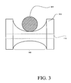
- FIG. 3 is a cross-sectional illustration of a portion of the force sensing system, at load pulley 104, adapted for a cable type of flexible member.
- Cable channel 302 is designed to geometrically conform to the shape of cable 301 in order to securely retain cable 301 within load pulley 104.
- FIG. 4 is a flowchart illustrating the exemplary method for sensing and measuring a tension load generated in the flexible member of the force sensing system.
- a tension load 113 is generated in belt 101 when the selected weight plates of weight stack 112 are lifted by a user of the exercise machine.
- a corresponding radial force exerted at load pulley 104 by belt 101 stresses the fixed axis of load pulley 104 to cause a physical strain thereon.
- force sensor cell 105 senses the physical strain at the axis of load pulley, and generates an amplified output voltage signal which is proportional thereto, having been amplified by amplifier circuit 109.
- analog to digital converter 114 converts the amplified voltage signal to a digital output voltage signal suitable for processing by processor 108.
- the force sensing system is calibrated to establish and predetermine a correlation between tension load 113 and output voltage signal of force sensor cell 105.
- the correlation between tension load 113 and output voltage signal of force sensor cell 105 is not limited to a linear form, and may comprise alternate forms, such as a polynomial form.
- one weight at the lower end of the range of weights in weight stack 112 another weight at the upper end of the range of weights, and then other intermediate weights within the upper and lower end of the range of weights for the weight stack exercise machine.
- the corresponding output voltage is recorded.
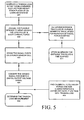
- FIG. 5 is a flowchart further illustrating the exemplary method for sensing and measuring a tension load generated in the flexible member of the force sensing system that further incorporates measuring and storing the distance travelled and time elapsed.
- the rotation of load pulley 104 is sensed by optical encoder 107, which transfers the rotation information to processor 108 for calculating the corresponding linear distance travelled by belt 101.
- the time elapsed during the rotation of load pulley 104 may also be measured by processor 108, and communicated to memory 110.
- the distance travelled and the time elapsed are stored in memory 110.
- the force measurement data and/or position measurement data may be used to determine the amount of range of motion performed by the person exercising on the exercise machine in real time.
- the measurements, range of motion, and/or information gleaned from processing the measurements may be sent from memory 110 to a display or reporting system.
- Possible forms of display and reporting may include visual display, audio or other user output.
- a numeric display viewable by the user may indicate the precise weight being lifted.
- Lights of different colors (e.g. red, yellow and green) in a display viewable by the user may indicate the actual range of motion relative to a possible range of motion, and may indicate whether the load being lifted is at, below or above a prescribed weight.
Landscapes
- Physics & Mathematics (AREA)
- General Physics & Mathematics (AREA)
- Chemical & Material Sciences (AREA)
- Analytical Chemistry (AREA)
- Force Measurement Appropriate To Specific Purposes (AREA)
Applications Claiming Priority (1)
| Application Number | Priority Date | Filing Date | Title |
|---|---|---|---|
| US94872407P | 2007-07-10 | 2007-07-10 |
Publications (2)
| Publication Number | Publication Date |
|---|---|
| EP2017594A2 true EP2017594A2 (fr) | 2009-01-21 |
| EP2017594A3 EP2017594A3 (fr) | 2009-03-25 |
Family
ID=39789768
Family Applications (1)
| Application Number | Title | Priority Date | Filing Date |
|---|---|---|---|
| EP08252342A Withdrawn EP2017594A3 (fr) | 2007-07-10 | 2008-07-09 | Système de détection de force pour élément flexible tendu |
Country Status (3)
| Country | Link |
|---|---|
| US (1) | US8069737B2 (fr) |
| EP (1) | EP2017594A3 (fr) |
| CA (1) | CA2637327A1 (fr) |
Cited By (3)
| Publication number | Priority date | Publication date | Assignee | Title |
|---|---|---|---|---|
| EP2233176A1 (fr) * | 2009-03-18 | 2010-09-29 | Joong Chenn Industry Co., Ltd. | Appareil d'exercice |
| ES2362966A1 (es) * | 2009-11-26 | 2011-07-18 | Centre Internacional De Metodes Numerics En Enginyeria | Sistema y método de medida de fuerzas aplicable a la medida de la fuerza aplicada a un sistema mecánico, y pieza de anclaje con sistema de medida integrado. |
| EP3643672A1 (fr) * | 2018-10-24 | 2020-04-29 | ContiTech Antriebssysteme GmbH | Procédé et dispositif de mesure de la force de précontrainte d'une courroie d'entraînement |
Families Citing this family (13)
| Publication number | Priority date | Publication date | Assignee | Title |
|---|---|---|---|---|
| US8864631B1 (en) * | 2008-02-19 | 2014-10-21 | Kenneth W Stearns | Exercise methods and apparatus |
| DE102010044864A1 (de) * | 2010-09-09 | 2012-03-15 | Gm Global Technology Operations Llc (N.D.Ges.D. Staates Delaware) | Steuerung einer variierbaren Spanneinrichtung für einen Keilrippenriemen eines Kraftfahrzeugantriebs |
| WO2013003937A1 (fr) * | 2011-05-13 | 2013-01-10 | Litens Automotive Partnership | Système et procédé d'entraînement intelligent par courroie |
| DE102013014265A1 (de) * | 2013-08-27 | 2015-03-05 | Liebherr-Components Biberach Gmbh | Vorrichtung zur Erkennung der Ablegereife eines hochfesten Faserseils beim Einsatz an Hebezeugen |
| CN104627883B (zh) * | 2014-12-29 | 2018-03-09 | 合肥工业大学 | 多功能模块化柔索导向装置及其检测方法 |
| US11235201B2 (en) * | 2017-06-04 | 2022-02-01 | Shapelog, Inc. | Weight machine sensor |
| US11473989B2 (en) * | 2018-07-31 | 2022-10-18 | Illinois Tool Works Inc. | Multi-dimensional sheave for use in tension measurement systems |
| US20210077849A1 (en) * | 2019-09-13 | 2021-03-18 | Vertimax, Llc | Smart pulley |
| US11759691B2 (en) * | 2019-11-14 | 2023-09-19 | Destro Machines LLC | Tethered resistance swim training apparatus with smart pulley |
| CN114894624B (zh) * | 2022-07-14 | 2022-11-01 | 浙大城市学院 | 基于海洋管线群锚作用的拉拔力测量试验装置及测量方法 |
| KR102564658B1 (ko) * | 2022-11-08 | 2023-08-08 | (주)스포투 | 웨이트 트레이닝 기구용 센서 모듈 |
| WO2024127087A2 (fr) * | 2022-12-16 | 2024-06-20 | 4Iiii Innovations Inc. | Système de force connectée pour équipement d'entraînement physique |
| GB2642333A (en) * | 2024-07-03 | 2026-01-07 | Waterrower Uk Ltd | Rowing machine metric measurment assembly |
Family Cites Families (13)
| Publication number | Priority date | Publication date | Assignee | Title |
|---|---|---|---|---|
| US4290598A (en) * | 1980-03-04 | 1981-09-22 | Flannery Matt W | Tension exerciser |
| JPS57161344A (en) * | 1981-03-27 | 1982-10-04 | Nippon Denso Co Ltd | Belt tension control device |
| GB2136582A (en) * | 1983-03-08 | 1984-09-19 | Lancier Masch Peter | Measuring electrically parameters of a cable being laid |
| DE3511930C2 (de) * | 1985-04-01 | 1987-03-12 | Aktiengesellschaft für industrielle Elektronik AGIE, Losone, Locarno | Vorrichtung zum Entsorgen einer verbrauchten band- oder drahtförmigen Elektrode einer Elektroerosionsmaschine durch Zerkleinern |
| US4827805A (en) * | 1987-01-08 | 1989-05-09 | Ford Motor Company | Forward and reverse clutch actuation system for a belt-driven continually variable transmission |
| US5302161A (en) * | 1990-03-28 | 1994-04-12 | Noordictrack, Inc. | Flexible line guidance and tension measuring device |
| GB2246199B (en) * | 1990-07-16 | 1994-02-09 | Hugh Michael Oppen Pratt | Load measuring device |
| US5167159A (en) * | 1990-12-18 | 1992-12-01 | Lucking William M | Tension transducer |
| US5728953A (en) * | 1996-10-04 | 1998-03-17 | United States Department Of Energy | Cable load sensing device |
| US7083554B1 (en) * | 1997-02-27 | 2006-08-01 | Nautilus, Inc. | Exercise machine with infinite position range limiter and automatic belt tensioning system |
| US20030097885A1 (en) * | 2001-09-24 | 2003-05-29 | Kell Terrance A. | Lateral displacement tensiometer and method for measuring tension |
| US6901818B1 (en) * | 2002-12-05 | 2005-06-07 | Maxwell C. Cheung | Tension measuring device for mooring line |
| JP2007137535A (ja) * | 2005-11-15 | 2007-06-07 | Ricoh Co Ltd | ベルト駆動制御装置及びこれを備えた画像形成装置 |
-
2008
- 2008-07-03 US US12/167,654 patent/US8069737B2/en not_active Expired - Fee Related
- 2008-07-04 CA CA002637327A patent/CA2637327A1/fr not_active Abandoned
- 2008-07-09 EP EP08252342A patent/EP2017594A3/fr not_active Withdrawn
Cited By (4)
| Publication number | Priority date | Publication date | Assignee | Title |
|---|---|---|---|---|
| EP2233176A1 (fr) * | 2009-03-18 | 2010-09-29 | Joong Chenn Industry Co., Ltd. | Appareil d'exercice |
| ES2362966A1 (es) * | 2009-11-26 | 2011-07-18 | Centre Internacional De Metodes Numerics En Enginyeria | Sistema y método de medida de fuerzas aplicable a la medida de la fuerza aplicada a un sistema mecánico, y pieza de anclaje con sistema de medida integrado. |
| WO2011098625A1 (fr) * | 2009-11-26 | 2011-08-18 | Centre Internacional De Métodes Numèrics En Enginyeria | Système et procédé de mesure de forces à utiliser pour mesurer une force appliquée sur un système mécanique, et pièce d'ancrage à système de mesure intégré |
| EP3643672A1 (fr) * | 2018-10-24 | 2020-04-29 | ContiTech Antriebssysteme GmbH | Procédé et dispositif de mesure de la force de précontrainte d'une courroie d'entraînement |
Also Published As
| Publication number | Publication date |
|---|---|
| EP2017594A3 (fr) | 2009-03-25 |
| US8069737B2 (en) | 2011-12-06 |
| CA2637327A1 (fr) | 2009-01-10 |
| US20090013804A1 (en) | 2009-01-15 |
Similar Documents
| Publication | Publication Date | Title |
|---|---|---|
| US8069737B2 (en) | Force sensing system for a tensioned flexible member | |
| US20200000031A1 (en) | Methods systems and apparatus for monitoring yield while harvesting grain | |
| AU646058B2 (en) | Load measuring device | |
| US9939309B2 (en) | Weighing device and method with off-center indication | |
| US8011242B2 (en) | System and device for measuring and analyzing forces applied by a cyclist on a pedal of a bicycle | |
| CN103565414B (zh) | 粘弹性测量装置 | |
| US20170356816A1 (en) | Systems and methods for measuring drivetrain power transmission | |
| US7126065B2 (en) | Weighing scale adapted for allowing a user to find an optical weighing position on the scale | |
| CN102741673B (zh) | 用于自动校准应变或力传感器的方法和装置 | |
| US7483795B2 (en) | Pressure and temperature compensation algorithm for use with a piezo-resistive strain gauge type pressure sensor | |
| KR890008554A (ko) | 힘 또는 모먼트 측정장치 교정방법 및 장치 | |
| EP0541354A2 (fr) | Machine d'essai de pneus avec procédé et appareil de calibrage | |
| US3603416A (en) | Weighing apparatus for belt conveyor | |
| EP1480024A3 (fr) | Dispositif pour la mesure du poids d'une charge | |
| CA1201134A (fr) | Courroie transporteuse-peseuse | |
| KR100890639B1 (ko) | 밸런스 측정 장치 | |
| US20240247970A1 (en) | Weight detection system for a lifting device | |
| US7191072B2 (en) | Pressure and temperature measurement of a piezo-resistive device using differential channel of a ratiometric analog to digital converter | |
| WO2007143838A9 (fr) | Cellule de charge à profil bas | |
| CN2219493Y (zh) | 可卸荷式钢丝绳张力检测仪 | |
| GB2642333A (en) | Rowing machine metric measurment assembly | |
| KR102831798B1 (ko) | 중량 측정 기능을 갖는 롤러 장치 및 컨베이어 벨트 | |
| CN211365407U (zh) | 一种砝码管理装置 | |
| JPS6217694Y2 (fr) | ||
| KR200271209Y1 (ko) | 체중계 겸용 디지털 벽시계 |
Legal Events
| Date | Code | Title | Description |
|---|---|---|---|
| PUAI | Public reference made under article 153(3) epc to a published international application that has entered the european phase |
Free format text: ORIGINAL CODE: 0009012 |
|
| AK | Designated contracting states |
Kind code of ref document: A2 Designated state(s): AT BE BG CH CY CZ DE DK EE ES FI FR GB GR HR HU IE IS IT LI LT LU LV MC MT NL NO PL PT RO SE SI SK TR |
|
| AX | Request for extension of the european patent |
Extension state: AL BA MK RS |
|
| PUAL | Search report despatched |
Free format text: ORIGINAL CODE: 0009013 |
|
| AK | Designated contracting states |
Kind code of ref document: A3 Designated state(s): AT BE BG CH CY CZ DE DK EE ES FI FR GB GR HR HU IE IS IT LI LT LU LV MC MT NL NO PL PT RO SE SI SK TR |
|
| AX | Request for extension of the european patent |
Extension state: AL BA MK RS |
|
| AKX | Designation fees paid | ||
| REG | Reference to a national code |
Ref country code: DE Ref legal event code: 8566 |
|
| STAA | Information on the status of an ep patent application or granted ep patent |
Free format text: STATUS: THE APPLICATION IS DEEMED TO BE WITHDRAWN |
|
| 18D | Application deemed to be withdrawn |
Effective date: 20090926 |