EP2017566B1 - Schnellkupplung, insbesondere für den Schaft einer tragbaren Waffe - Google Patents
Schnellkupplung, insbesondere für den Schaft einer tragbaren Waffe Download PDFInfo
- Publication number
- EP2017566B1 EP2017566B1 EP08012290.6A EP08012290A EP2017566B1 EP 2017566 B1 EP2017566 B1 EP 2017566B1 EP 08012290 A EP08012290 A EP 08012290A EP 2017566 B1 EP2017566 B1 EP 2017566B1
- Authority
- EP
- European Patent Office
- Prior art keywords
- stock
- weapon
- coupling according
- plate
- main body
- Prior art date
- Legal status (The legal status is an assumption and is not a legal conclusion. Google has not performed a legal analysis and makes no representation as to the accuracy of the status listed.)
- Active
Links
Images

Classifications
-
- F—MECHANICAL ENGINEERING; LIGHTING; HEATING; WEAPONS; BLASTING
- F41—WEAPONS
- F41A—FUNCTIONAL FEATURES OR DETAILS COMMON TO BOTH SMALLARMS AND ORDNANCE, e.g. CANNONS; MOUNTINGS FOR SMALLARMS OR ORDNANCE
- F41A3/00—Breech mechanisms, e.g. locks
- F41A3/64—Mounting of breech-blocks; Accessories for breech-blocks or breech-block mountings
- F41A3/66—Breech housings or frames; Receivers
-
- F—MECHANICAL ENGINEERING; LIGHTING; HEATING; WEAPONS; BLASTING
- F41—WEAPONS
- F41C—SMALLARMS, e.g. PISTOLS, RIFLES; ACCESSORIES THEREFOR
- F41C23/00—Butts; Butt plates; Stocks
- F41C23/10—Stocks or grips for pistols, e.g. revolvers
-
- F—MECHANICAL ENGINEERING; LIGHTING; HEATING; WEAPONS; BLASTING
- F41—WEAPONS
- F41C—SMALLARMS, e.g. PISTOLS, RIFLES; ACCESSORIES THEREFOR
- F41C23/00—Butts; Butt plates; Stocks
- F41C23/14—Adjustable stock or stock parts, i.e. adaptable to personal requirements, e.g. length, pitch, cast or drop
Definitions
- the present invention relates to a quick coupling particularly for the stock of a portable weapon.
- the plate or plates that determine the drop and cast are generally interposed between the stock and the member of the weapon onto which the stock is to be fitted, while the fixing plate is generally fitted on a tube or tension member which constitutes the extension of the weapon inside the stock and is fixed thereon by a screw or a nut.
- EP-1574807 discloses a stock mounting system for rifles comprising a springloaded bolt having an end that engages with a seating on the gun housing. Such stock mounting system does not provide for a quick coupling and requires a tool for assembling and disassembling the stock.
- the aim of the present invention is to provide a quick coupling which overcomes the drawbacks of the cited prior art.
- an object of the present invention is to provide a quick coupling for the stock of a portable weapon which can be disassembled without requiring particular tools and automatically provides the selected drop and cast of the stock upon its coupling to the weapon.
- Another object of the invention is to allow to vary the trim of the stock simply by replacing a single component without having to disassemble other components of the weapon or stock which do not strictly belong to the quick coupling system.
- the quick coupling for stocks of portable weapons comprises a main annular body which has externally threaded sectors and a cylindrical stem for centering on the stock which is internally hollow in order to accommodate Belleville springs fitted thereon by means of a nut which is provided with an extended external shank which passes internally through the Belleville springs and through the main body in order to allow assembly by means of a snap ring which Is fitted to the portion of the outer shank of the nut that protrudes from the main body
- the Belleville springs when the assembly is assembled, are still not preloaded, both to allow their easy assembly and to facilitate the screwing of the nut onto the corresponding threaded pin or tension member fitted on the stock.
- the quick coupling for stocks of portable weapons also comprises a threaded pin which is fitted directly onto the stock where the cylindrical portion of the main body, which constitutes the engagement member of the quick coupling, is accommodated.
- the cylindrical portion of the main body In order to ensure that the cylindrical portion of the main body is properly registered on the stock, it is centered on a plate which is contoured and locked to the stock by a screw and a nut so as to provide a compact and rigid structure which might also be manufactured by overmolding of the contoured plate on the stock, if the stock is made of technopolymer.
- Plates of different shapes may be fit, between the main body of the quick coupling and the front plane of the stock that rests on the weapon.
- the plates are accordingly interchangeable and ensure the drop and cast of the stock by way of the strong compression of the Belleville springs which can be obtained when the entire quick coupling is screwed against the front plane of the stock.
- the Belleville springs are further compressed when the entire stock, complete with the quick coupling, engages by rotation on the portion of the weapon where its coupling seat is provided, so as to eliminate any small free movement of the stock caused by to the coupling tolerances of the various components.
- the front plane of the weapon which surrounds the coupling seat of the quick coupling, provided on the barrel extension or on the receiver, adheres to the interchangeable plate, which is provided in order to determine the drop and cast of the stock, transferring its drop and cast characteristics to the stock without locking the stock rigidly to the weapon.
- the kinetic energy of the recoil of the weapon further compresses the Belleville springs of the quick coupling without however affecting the drop and cast of the stock but further dissipating partly before being released against the shoulder of the shooter.
- the quick coupling for stocks of portable weapons according to the present invention is provided with references signs, such as pins or slots, to ensure that the entire quick coupling is fitted on the stock with the correct orientation with respect to the interface of the weapon on which it engages so as to achieve, when the coupling rotation is completed, the correct fitting of the entire stock to the weapon.
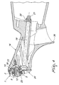
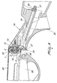
- Figure 7 is a sectional perspective view of the quick coupling as fitted to the stock of the weapon, in the quick coupling position, screwed onto its seat provided on the sheath or barrel extension and with the receiver or guard completely assembled.
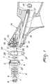
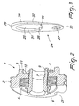
- the quick coupling according to the invention comprises an annular main body 1 provided with threaded sectors 2, a cylindrical shank 3 for centering on the stock, and an internal seat 4 for Belleville springs 5.
- a fastening nut 6 is provided with a shank 7 which passes internally through the Belleville springs 5 and through the main annular body 1 to ensure the assembly of the Belleville springs 5 on the main annular body 1 by means of a snap ring 8 which engages on a seat 9 thereof, which is provided at the rear end of the shank 7 of the fixing nut 6.
- the main annular body 1 does not have assembly difficulties, because the entire assembled set still keeps the Belleville springs 5 and the nut 6 free to move by way of an axial play 10, which is ensured between a shoulder plane 11 of the main body 1 and the snap ring 8.
- the entire annular main body 1 in the assembled condition can therefore be screwed freely, at least in the initial step, on a threaded shank 12 of the tension member 13 which is fitted on the stock 14.
- centering plate 15 which is shaped in order to obtain both a circular centering seat 16 for the cylindrical shank 3 of the main body 1 and a seat 17 for the head 18 of the screw 19, which rigidly couples the centering plate 15 to the stock 14 when it is locked by screwing forcefully the self-locking nut 20 to the threaded end 21 of the screw 19.
- the threaded sectors 2 of the main body 1, which is assembled as shown in Figure 2 , are oriented correctly on the stock 14 by an orientation pin 22, which is fitted on the stock 14 by virtue of a groove 23 formed on the main body 1.
- the groove 23 perfectly combines with the orientation pin 22 in order to allow the mating of the cylindrical centering shank 3 of the main body 1 with the internal seat 16 of the centering plate 15, so as to define a single possible assembly position.
- the quick coupling offers the possibility to provide the stock 14 with a specific drop and cast, with respect to the aiming line of the weapon, by way of an adjustment member constituted by an abutment plate 24.
- the abutment plate 24, shown in Figure 3 is provided with a central hole 25, with two grooves 26, and with a slot 27.
- the thickness 28 of the plate 24 is conveniently determined in relation to the drop and cast that the stock 14 must have with respect to the aiming line of the weapon.
- the thickness 28 of the plate 24 is therefore different, both when considered on its vertical axis and when considered on its horizontal axis, both of which pass through the central hole 25, as can be seen clearly by observing respectively the points 29 and 30, considered for the vertical axis of the plate 24, and the points 31 and 32, considered for the horizontal axis of the plate.
- the inclination determined by the thickness variation that can be observed between the points 31 and 32 of the plate 24 corresponds to a given lateral cast value of the stock 14 with respect to the barrel axis of the weapon.
- This value is usually constant, regardless of the various drop values that the stock 14 can assume, and therefore all the plates optionally provided with the weapon have the same thickness variation observable between the respective points 31 and 32.
- Each plate 24, is provided with two grooves 26 and can be registered on the orientation pin 22 in two different positions, the one shown in Figure 1 and the one that can be obtained by flipping the plate over, through 180°, about its vertical axis, so as to have, in the first case, a given right cast of the stock 14 with respect to the aiming line of the weapon and, in the second case, a similar left cast of the stock 14.
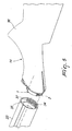
- FIG. 4 shows the complete system with the tension member 13 screwed onto the stock 14, the centering plate 15, accommodated and locked on the stock 14 by the screw 19, and the self-locking nut 20, the plate 24 interposed between the stock 14 and the main annular body 1.
- Annular body 1 is assembled as shown in Figure 2 and is oriented by means of the groove 23 on the orientation pin 22.
- Annular body 1 is screwed completely, by way of the nut 6, onto the threaded stem 12 of the tension member 13, determining such a compression of the Belleville springs 5 as to ensure perfect adhesion between the stock 14, the plate 24 and the main annular body 1.
- the stock complete with the quick coupling according to the present invention, according to this embodiment, is fitted onto the weapon on the barrel extension 33 of the weapon.
- Screwing occurs rapidly, by inserting the entire main annular body 1 in the barrel extension 33, taking care, during insertion, to align its threaded sectors 2 with the recesses 35, which are also provided inside the barrel extension 33, the alignment being easily obtainable by keeping the pistol grip of the stock 36 in a transverse position with respect to the vertical axis of the weapon, i.e., at 90°, and then screwing together the threaded sectors 2 of the main annular body 1 and the respective threaded sectors 34 of the sheath or barrel extension 33, with a rotary motion of the stock which has an end rotation position determined automatically by contact of the orientation pin 22 against the end portion 37 of the recess 35 cited above.
- the drop and cast given to the plate 24 is transferred to the stock 14 of the weapon and the stock is fitted with a given drop value and a given cast value with respect to the aiming line of the weapon.
- the Belleville springs 5 have not yet reached their point of maximum compression, and therefore upon firing the kinetic energy of the recoil of the weapon can further compress the Belleville springs 5 without significantly affecting the drop and cast of the stock, simply dissipating partially before being discharged against the shoulder of the shooter.
- the plate 24 is provided with the slot 27, on which the rear end 38 of the guard or receiver 39 of the weapon can be registered.
- Figure 7 shows the entire system completely assembled, with the rear end 38 of the guard or receiver 39 completely inserted on the slot 27 of the plate 24.
- the quick coupling according to the present invention also allows to determine automatically the drop and cast when the stock is fitted onto the weapon.
- Another advantage of the quick coupling according to the present invention is that it can be easily implemented on any portable weapon and the coupling on the weapon can occur both on its sheath or barrel extension and on the receiver or other conventional components for the weapons being considered.
- the coupling point can vary according to the requirements, i.e., according to the design and construction characteristics of the portable weapon to which the stock is to be applied.
- the interchangeability of the plate allows to have the same stock fitted on the weapon with drops and casts which are variable as a function of the requirements of the user.
- plates with different drop and cast trims are manufactured and provided to the user. The user can thus have at his disposal one or more plates suitable for his requirements.
- Another advantage of the invention is that, when using the weapon, upon firing, the kinetic energy of the recoil of the weapon can further compress the Belleville springs of the coupling, without affecting the drop and cast of the stock, and partially dissipating before being released against the shoulder of the shooter.
Landscapes
- Engineering & Computer Science (AREA)
- General Engineering & Computer Science (AREA)
- Aiming, Guidance, Guns With A Light Source, Armor, Camouflage, And Targets (AREA)
- Toys (AREA)
- Adornments (AREA)
- Purses, Travelling Bags, Baskets, Or Suitcases (AREA)
- Lock And Its Accessories (AREA)
- Sheet Holders (AREA)
- Mechanical Pencils And Projecting And Retracting Systems Therefor, And Multi-System Writing Instruments (AREA)
- Manufacture Of Alloys Or Alloy Compounds (AREA)
- Casings For Electric Apparatus (AREA)
Claims (13)
- Eine Schnellkopplung, insbesondere für den Schaft einer tragbaren Waffe, die einen elastisch verformbaren Körper (1, 5, 6, 7) aufweist, montiert auf den Schaft (14) einer tragbaren Waffe und ausgestattet mit einem Eingriffsmittel (2) zum Eingreifen in eine Komponente (33) der tragbaren Waffe, wobei der elastisch verformbare Körper (1, 5, 6, 7) eine Position hat, die nicht elastisch verformt ist, und eine Position, die elastisch verformt ist, wobei der elastisch verformbare Körper (1, 5, 6, 7) in der elastisch verformten Position in die Komponente (33) der tragbaren Waffe eingreift; wobei die Schnellkopplung dadurch gekennzeichnet ist, dass der elastisch verformbare Körper (1, 5, 6, 7) einen Aufbau aufweist, der aus einem ringförmigen Hauptkörper (1) besteht, welcher durch elastische Glieder (5) mit einem axialen Glied (6, 7) verbunden ist, wobei das axiale Glied (6, 7) starr mit dem Schaft (14) verbunden ist.
- Die Kopplung gemäß Anspruch 1, dadurch gekennzeichnet, dass sie ein Anpassungsglied aufweist, das zwischen dem elastisch verformbaren Körper (1, 5, 6, 7) und dem Schaft (14) angeordnet ist und geeignet ist, den Drop and Cast des Schafts (14) im Verhältnis zu dem elastisch verformbaren Körper (1, 5, 6, 7) und somit im Verhältnis zu der tragbaren Waffenkomponente (33) zu bestimmen.
- Die Kopplung gemäß Anspruch 1, dadurch gekennzeichnet, dass das Eingriffsmittel in einem Teilgewinde (2) besteht.
- Die Kopplung gemäß einem oder mehreren der obigen Ansprüche, dadurch gekennzeichnet, dass der ringförmige Hauptkörper (1) Abschnitte (2) mit Außengewinde aufweist, welche das Eingriffsmittel bilden, und einen inneren Hohlraum (4), der geeignet ist, eine oder mehrere Tellerfedern (5), die die elastischen Mittel bilden, und einen zylindrischen Zentrierschaft (7) aufzunehmen, der das axiale Glied bildet, wobei die Tellerfedern (5) mit Hilfe einer Mutter (6) auf den Zentrierschaft (7) montiert werden, die mit einer äußeren Erweiterung versehen ist und innen durch die Tellerfedern (5) und den ringförmigen Hauptkörper (1) dringt, wobei ein Spaltring (8) an der äußeren Erweiterung montiert ist.
- Die Kopplung gemäß einem oder mehreren der obigen Ansprüche, dadurch gekennzeichnet, dass der Zentrierschaft (7) hohl ist und ein Innengewinde aufweist, das geeignet ist, einen Gewindestift (12) zu halten, welcher starr mit dem Schaft (14) verbunden ist.
- Die Kopplung gemäß einem oder mehreren der obigen Ansprüche, dadurch gekennzeichnet, dass, wenn der Aufbau (1, 5, 6, 7), bestehend aus dem ringförmigen Hauptkörper (1), der durch die Tellerfedern (5) mit dem Zentrierschaft (7) verbunden ist, zusammengebaut wird, die Tellerfedern (5) nicht vorgespannt sind, um ein leichtes Aufschrauben des Zentrierschafts (7) auf den Gewindestift (12) zu ermöglichen.
- Die Kopplung gemäß einem oder mehreren der obigen Ansprüche, dadurch gekennzeichnet, dass der Hauptkörper (1) mit dem Schaft (14) über ein Zentrierglied (15) verbunden ist, das starr mit dem Schaft (14) gekoppelt ist.
- Die Kopplung gemäß einem oder mehreren der obigen Ansprüche, dadurch gekennzeichnet, dass das Zentrierglied aus einer konturierten Platte (15) besteht, die durch eine Schraube (19) mit dem Schaft (14) verbunden ist, wobei die konturierte Platte (15) einen kreisförmigen Zentriersitz (16) aufweist, der geeignet ist, einen zylindrischen Abschnitt (3) des ringförmigen Hauptkörpers (1) aufzunehmen, und einen Sitz (17) zur Aufnahme eines Kopfes (18) der Schraube (19), die die konturierte Platte (15) starr mit dem Schaft (14) koppelt.
- Die Kopplung gemäß einem oder mehreren der obigen Ansprüche, dadurch gekennzeichnet, dass sie einen Ausrichtungsstift (22) umfasst, der starr mit dem Schaft (14) gekoppelt und geeignet ist, in eine Nut (23) einzugreifen, die in dem Hauptkörper (1) geformt ist, wenn der Hauptkörper (1) auf den Schaft (14) montiert ist, um so eine einzige mögliche Position für den Aufbau des Hauptkörpers (1) im Verhältnis zu der konturierten Platte (15) zu bestimmen, die starr mit dem Schaft (14) gekoppelt ist.
- Die Kopplung gemäß einem oder mehreren der obigen Ansprüche, dadurch gekennzeichnet, dass das Anpassungsglied, das zwischen dem elastisch verformbaren Körper (1, 5, 6, 7) und dem Schaft (14) angeordnet ist, in einer konturierten Widerlagerplatte (24) besteht.
- Die Kopplung gemäß einem oder mehreren der obigen Ansprüche, dadurch gekennzeichnet, dass die Widerlagerplatte (24) eine Dicke (28) hat, die differenziert und determiniert im Verhältnis zum Drop and Cast ist, das der Schaft (14) mit Bezug auf die Ziellinie der Waffe haben muss.
- Die Kopplung gemäß einem oder mehreren der obigen Ansprüche, dadurch gekennzeichnet, dass die Dicke (28) der Widerlagerplatte (24) verändert wird, sowohl in Bezug auf ihre Vertikalachse als auch auf ihre Horizontalachse, wobei sowohl die Vertikal- als auch die Horizontalachse durch ein zentrales Loch (25) der Widerlagerplatte (24) verlaufen.
- Die Kopplung gemäß einem oder mehreren der obigen Ansprüche, dadurch gekennzeichnet, dass die Widerlagerplatte zwei Nuten (26) umfasst, die jeweils geeignet sind, den Ausrichtungsstift (22) aufzunehmen, der fest mit dem Schaft (14) verbunden ist, so dass die Widerlagerplatte (24) in zwei Positionen, eine gekippt im Verhältnis zur anderen, auf dem Schaft (14) montiert werden kann, um so mit der Widerlagerplatte (24) den Cast zu variieren, den der Schaft (14) mit Bezug auf die Ziellinie der Waffe haben muss.
Priority Applications (3)
| Application Number | Priority Date | Filing Date | Title |
|---|---|---|---|
| PL08012290T PL2017566T3 (pl) | 2007-07-20 | 2008-07-08 | Szybkozłącze, przeznaczone w szczególności do kolby broni ręcznej |
| SI200831129T SI2017566T1 (sl) | 2007-07-20 | 2008-07-08 | Hitra spojka posebno za ročaj prenosnega orožja |
| CY20141100009T CY1114813T1 (el) | 2007-07-20 | 2014-01-07 | Ταχυσυνδεσμος ιδιαιτερα για το κοντακι ενος φορητου οπλου |
Applications Claiming Priority (1)
| Application Number | Priority Date | Filing Date | Title |
|---|---|---|---|
| IT001472A ITMI20071472A1 (it) | 2007-07-20 | 2007-07-20 | Attacco ad innesto rapido, particolarmente per il calcio di un'arma portatile |
Publications (3)
| Publication Number | Publication Date |
|---|---|
| EP2017566A2 EP2017566A2 (de) | 2009-01-21 |
| EP2017566A3 EP2017566A3 (de) | 2012-10-24 |
| EP2017566B1 true EP2017566B1 (de) | 2013-12-04 |
Family
ID=39865461
Family Applications (1)
| Application Number | Title | Priority Date | Filing Date |
|---|---|---|---|
| EP08012290.6A Active EP2017566B1 (de) | 2007-07-20 | 2008-07-08 | Schnellkupplung, insbesondere für den Schaft einer tragbaren Waffe |
Country Status (16)
| Country | Link |
|---|---|
| US (1) | US7748154B2 (de) |
| EP (1) | EP2017566B1 (de) |
| JP (1) | JP5362278B2 (de) |
| CN (1) | CN101408393B (de) |
| BR (1) | BRPI0803823B1 (de) |
| CY (1) | CY1114813T1 (de) |
| DK (1) | DK2017566T3 (de) |
| EA (1) | EA015049B1 (de) |
| ES (1) | ES2441847T3 (de) |
| HR (1) | HRP20131219T1 (de) |
| IL (1) | IL192752A (de) |
| IT (1) | ITMI20071472A1 (de) |
| MX (1) | MX2008009335A (de) |
| PL (1) | PL2017566T3 (de) |
| PT (1) | PT2017566E (de) |
| SI (1) | SI2017566T1 (de) |
Families Citing this family (25)
| Publication number | Priority date | Publication date | Assignee | Title |
|---|---|---|---|---|
| US7823315B2 (en) * | 2005-10-20 | 2010-11-02 | O.F. Mossberg & Sons, Inc. | Method and apparatus for easy connect stocks |
| US8522468B2 (en) | 2005-10-20 | 2013-09-03 | O.F. Mossberg & Sons, Inc. | Easy connect forend assembly |
| US9057576B2 (en) | 2009-03-24 | 2015-06-16 | Sturm, Ruger & Company, Inc. | Firearm with quick coupling barrel system |
| US8479429B2 (en) | 2009-03-24 | 2013-07-09 | Sturm, Ruger & Company, Inc. | Firearm with quick coupling barrel system |
| US8490312B2 (en) | 2009-03-24 | 2013-07-23 | Sturm, Ruger & Company, Inc. | Quick coupling barrel system for firearm |
| US8505227B2 (en) | 2009-03-24 | 2013-08-13 | Sturm, Ruger & Company, Inc. | Firearm with quick coupling barrel interlock system |
| WO2011065930A1 (en) * | 2009-11-25 | 2011-06-03 | O.F. Mossberg & Sons, Inc. | Method and apparatus for easy connect stocks |
| ITMO20100105A1 (it) * | 2010-04-08 | 2011-10-09 | Andrea Checchi | Dispositivo di protezione della cassa di un'arma da fuoco |
| US9010009B2 (en) * | 2010-11-01 | 2015-04-21 | The Otis Patent Trust | Eccentric rail nut and eccentric rail mounting system |
| US8434252B2 (en) * | 2011-01-18 | 2013-05-07 | Gregory J. Holmberg | Recoil absorbing stock |
| DE102012101904A1 (de) * | 2012-03-07 | 2013-09-12 | Blaser Finanzholding Gmbh | Stutzenschaft |
| US8943728B2 (en) * | 2012-05-15 | 2015-02-03 | Magpul Industries Corp. | Fixed stock with integral storage |
| EP2943733B1 (de) | 2013-01-10 | 2019-02-27 | Sturm, Ruger & Company, Inc. | Austauschbares schaftsystem für feuerwaffen |
| US9488434B2 (en) * | 2014-12-19 | 2016-11-08 | Magpul Industries Corp. | Stock-firearm interface |
| US10088265B2 (en) * | 2016-02-09 | 2018-10-02 | James Matthew Underwood | Rear trunnion and folding stock fitting assemblies |
| US10161711B2 (en) * | 2016-12-01 | 2018-12-25 | Benelli Armi, S.P.A. | Portable firearm with quick coupling removable stock |
| US10036602B1 (en) | 2017-11-28 | 2018-07-31 | Magpul Industries Corp. | Interchangeable plates for a firearm |
| USD868924S1 (en) | 2018-01-10 | 2019-12-03 | Magpul Industries Corp. | Firearm stock |
| CN108801051B (zh) * | 2018-04-28 | 2020-02-07 | 沈阳理工大学 | 一种步枪枪托转换机构 |
| US11143486B2 (en) * | 2018-12-12 | 2021-10-12 | Daniel Defense, Llc | Stock with multiple structural inserts |
| IT201900007998A1 (it) * | 2019-06-04 | 2020-12-04 | Benelli Armi Spa | Calcio per arma |
| US11841208B1 (en) | 2020-06-24 | 2023-12-12 | Mark John Roth | Universally adjustable firearm stock |
| USD1001950S1 (en) | 2020-09-08 | 2023-10-17 | Mark John Roth | Stock framework |
| IT202100020003A1 (it) * | 2021-07-27 | 2023-01-27 | Valerio Poletti | Corpo carabina smontabile |
| US11892256B2 (en) * | 2022-02-22 | 2024-02-06 | David Maga | Ammunition magazine with self-locking mechanism |
Family Cites Families (18)
| Publication number | Priority date | Publication date | Assignee | Title |
|---|---|---|---|---|
| BE359816A (de) * | 1928-11-15 | |||
| US2790262A (en) * | 1952-09-29 | 1957-04-30 | Fred D Baker | Adjustable gunstock |
| DE1271598B (de) * | 1964-10-29 | 1968-06-27 | Rheinmetall Gmbh | Aus Baugruppen zusammengesetzte automatische Waffe |
| US3380182A (en) * | 1967-01-03 | 1968-04-30 | Browning Ind Inc | Receiver-stock assembly for firearm |
| FR2274885A1 (fr) * | 1974-06-17 | 1976-01-09 | Herstal Sa | Dispositif pour la fixation reglable d'une crosse de fusil |
| ES207609Y (es) * | 1974-11-19 | 1976-07-16 | Alonso Berbegal | Dispositivo de articulacion para culatas de armas de fuego largas. |
| US4148149A (en) * | 1978-01-25 | 1979-04-10 | Pachmayr Gun Works, Inc. | Cushioned gun grip |
| CN2044343U (zh) * | 1988-07-30 | 1989-09-13 | 胡建瑞 | 折托便携式气枪 |
| US4893426A (en) * | 1988-10-07 | 1990-01-16 | South Central Research Corp. | Lugged coupling apparatus |
| FR2686152B3 (fr) * | 1992-01-13 | 1993-12-17 | Alonso Berbegal Jose | Dispositif perfectionne permettant l'articulation de la crosse d'un fusil de chasse. |
| US5410833A (en) * | 1993-07-16 | 1995-05-02 | Paterson; Douglas F. | Recoil absorbing firearm stock |
| US6671990B1 (en) * | 2002-02-13 | 2004-01-06 | Vern H. Booth | Rifle handguard system with single end attachment |
| US6688031B2 (en) * | 2002-05-30 | 2004-02-10 | Gerald Dale Steele | Replacement adjustable competition buttstock |
| US6732466B2 (en) * | 2002-08-19 | 2004-05-11 | James K. Bentley | Recoil system for the receiver of a firearm |
| EP1574807B1 (de) * | 2004-03-09 | 2006-11-02 | S.A.T. Swiss Arms Technology AG | Schaftbefestigung für Handfeuerwaffen |
| US20070089347A1 (en) * | 2005-10-20 | 2007-04-26 | Webber Kevin A | Easy connect stock and forend system |
| US7640688B2 (en) * | 2006-06-16 | 2010-01-05 | Command Arms Accessories | Adjustable cheek rest and accessory rail for firearms |
| ITMI20071473A1 (it) * | 2007-07-20 | 2009-01-21 | Benelli Armi Spa | Arma portatile modulare |
-
2007
- 2007-07-20 IT IT001472A patent/ITMI20071472A1/it unknown
-
2008
- 2008-07-08 EP EP08012290.6A patent/EP2017566B1/de active Active
- 2008-07-08 DK DK08012290.6T patent/DK2017566T3/da active
- 2008-07-08 PL PL08012290T patent/PL2017566T3/pl unknown
- 2008-07-08 PT PT80122906T patent/PT2017566E/pt unknown
- 2008-07-08 US US12/217,764 patent/US7748154B2/en active Active
- 2008-07-08 SI SI200831129T patent/SI2017566T1/sl unknown
- 2008-07-08 ES ES08012290.6T patent/ES2441847T3/es active Active
- 2008-07-10 IL IL192752A patent/IL192752A/en active IP Right Grant
- 2008-07-18 CN CN200810175662.7A patent/CN101408393B/zh not_active Expired - Fee Related
- 2008-07-18 EA EA200801576A patent/EA015049B1/ru unknown
- 2008-07-18 MX MX2008009335A patent/MX2008009335A/es active IP Right Grant
- 2008-07-18 JP JP2008187582A patent/JP5362278B2/ja not_active Expired - Fee Related
- 2008-07-21 BR BRPI0803823-6A patent/BRPI0803823B1/pt not_active IP Right Cessation
-
2013
- 2013-12-23 HR HRP20131219AT patent/HRP20131219T1/hr unknown
-
2014
- 2014-01-07 CY CY20141100009T patent/CY1114813T1/el unknown
Also Published As
| Publication number | Publication date |
|---|---|
| MX2008009335A (es) | 2009-03-05 |
| IL192752A0 (en) | 2009-02-11 |
| IL192752A (en) | 2012-03-29 |
| HK1123351A1 (en) | 2009-06-12 |
| PT2017566E (pt) | 2014-01-10 |
| ES2441847T3 (es) | 2014-02-06 |
| JP5362278B2 (ja) | 2013-12-11 |
| JP2009041900A (ja) | 2009-02-26 |
| CY1114813T1 (el) | 2016-12-14 |
| BRPI0803823B1 (pt) | 2019-07-02 |
| BRPI0803823A2 (pt) | 2009-12-01 |
| US7748154B2 (en) | 2010-07-06 |
| ITMI20071472A1 (it) | 2009-01-21 |
| PL2017566T3 (pl) | 2014-05-30 |
| CN101408393A (zh) | 2009-04-15 |
| EP2017566A3 (de) | 2012-10-24 |
| US20090019757A1 (en) | 2009-01-22 |
| CN101408393B (zh) | 2015-07-15 |
| EP2017566A2 (de) | 2009-01-21 |
| SI2017566T1 (sl) | 2014-04-30 |
| EA200801576A1 (ru) | 2009-02-27 |
| EA015049B1 (ru) | 2011-04-29 |
| DK2017566T3 (da) | 2014-01-20 |
| HRP20131219T1 (hr) | 2014-03-14 |
Similar Documents
| Publication | Publication Date | Title |
|---|---|---|
| EP2017566B1 (de) | Schnellkupplung, insbesondere für den Schaft einer tragbaren Waffe | |
| US7162823B2 (en) | Firearm stock connector | |
| US11892260B2 (en) | Handguard for clamping mounting on an existing firearm | |
| US20050188591A1 (en) | Barrel assembly and attachment system | |
| US9175924B1 (en) | Tactical attachment system for firearms | |
| US20210180897A1 (en) | Pivot pin | |
| US12455134B2 (en) | Quick take-down firearm | |
| US10222157B2 (en) | Quick take-down firearm | |
| US11029125B2 (en) | Break open system having an adjustable, releasable forend stock | |
| US20240369325A1 (en) | Sight and accessory mount assembly for a firearm | |
| HK1123351B (en) | Quick coupling particularly for the stock of a portable weapon | |
| US20250283689A1 (en) | Handguard mounting system |
Legal Events
| Date | Code | Title | Description |
|---|---|---|---|
| PUAI | Public reference made under article 153(3) epc to a published international application that has entered the european phase |
Free format text: ORIGINAL CODE: 0009012 |
|
| AK | Designated contracting states |
Kind code of ref document: A2 Designated state(s): AT BE BG CH CY CZ DE DK EE ES FI FR GB GR HR HU IE IS IT LI LT LU LV MC MT NL NO PL PT RO SE SI SK TR |
|
| AX | Request for extension of the european patent |
Extension state: AL BA MK RS |
|
| REG | Reference to a national code |
Ref country code: HK Ref legal event code: DE Ref document number: 1123351 Country of ref document: HK |
|
| PUAL | Search report despatched |
Free format text: ORIGINAL CODE: 0009013 |
|
| AK | Designated contracting states |
Kind code of ref document: A3 Designated state(s): AT BE BG CH CY CZ DE DK EE ES FI FR GB GR HR HU IE IS IT LI LT LU LV MC MT NL NO PL PT RO SE SI SK TR |
|
| AX | Request for extension of the european patent |
Extension state: AL BA MK RS |
|
| RIC1 | Information provided on ipc code assigned before grant |
Ipc: F41A 3/66 20060101AFI20120920BHEP Ipc: F41C 23/14 20060101ALI20120920BHEP Ipc: F41C 23/10 20060101ALI20120920BHEP Ipc: F41A 23/20 20060101ALI20120920BHEP |
|
| 17P | Request for examination filed |
Effective date: 20130308 |
|
| AKX | Designation fees paid |
Designated state(s): AT BE BG CH CY CZ DE DK EE ES FI FR GB GR HR HU IE IS IT LI LT LU LV MC MT NL NO PL PT RO SE SI SK TR |
|
| RIC1 | Information provided on ipc code assigned before grant |
Ipc: F41C 23/10 20060101ALI20130617BHEP Ipc: F41C 23/14 20060101ALI20130617BHEP Ipc: F41A 3/66 20060101AFI20130617BHEP Ipc: F41A 23/20 20060101ALI20130617BHEP |
|
| GRAP | Despatch of communication of intention to grant a patent |
Free format text: ORIGINAL CODE: EPIDOSNIGR1 |
|
| INTG | Intention to grant announced |
Effective date: 20130731 |
|
| GRAS | Grant fee paid |
Free format text: ORIGINAL CODE: EPIDOSNIGR3 |
|
| GRAA | (expected) grant |
Free format text: ORIGINAL CODE: 0009210 |
|
| AK | Designated contracting states |
Kind code of ref document: B1 Designated state(s): AT BE BG CH CY CZ DE DK EE ES FI FR GB GR HR HU IE IS IT LI LT LU LV MC MT NL NO PL PT RO SE SI SK TR |
|
| REG | Reference to a national code |
Ref country code: GB Ref legal event code: FG4D |
|
| REG | Reference to a national code |
Ref country code: CH Ref legal event code: EP |
|
| REG | Reference to a national code |
Ref country code: HR Ref legal event code: TUEP Ref document number: P20131219 Country of ref document: HR |
|
| REG | Reference to a national code |
Ref country code: RO Ref legal event code: EPE |
|
| REG | Reference to a national code |
Ref country code: PT Ref legal event code: SC4A Free format text: AVAILABILITY OF NATIONAL TRANSLATION Effective date: 20140106 |
|
| REG | Reference to a national code |
Ref country code: NL Ref legal event code: T3 Ref country code: AT Ref legal event code: REF Ref document number: 643694 Country of ref document: AT Kind code of ref document: T Effective date: 20140115 Ref country code: IE Ref legal event code: FG4D |
|
| REG | Reference to a national code |
Ref country code: DK Ref legal event code: T3 Effective date: 20140117 |
|
| REG | Reference to a national code |
Ref country code: DE Ref legal event code: R096 Ref document number: 602008029055 Country of ref document: DE Effective date: 20140130 |
|
| REG | Reference to a national code |
Ref country code: SE Ref legal event code: TRGR |
|
| REG | Reference to a national code |
Ref country code: ES Ref legal event code: FG2A Ref document number: 2441847 Country of ref document: ES Kind code of ref document: T3 Effective date: 20140206 |
|
| REG | Reference to a national code |
Ref country code: NO Ref legal event code: T2 Effective date: 20131204 |
|
| REG | Reference to a national code |
Ref country code: GR Ref legal event code: EP Ref document number: 20130402773 Country of ref document: GR Effective date: 20140124 |
|
| REG | Reference to a national code |
Ref country code: HR Ref legal event code: T1PR Ref document number: P20131219 Country of ref document: HR |
|
| REG | Reference to a national code |
Ref country code: SK Ref legal event code: T3 Ref document number: E 15622 Country of ref document: SK |
|
| REG | Reference to a national code |
Ref country code: HK Ref legal event code: GR Ref document number: 1123351 Country of ref document: HK Ref country code: PL Ref legal event code: T3 |
|
| REG | Reference to a national code |
Ref country code: EE Ref legal event code: FG4A Ref document number: E009192 Country of ref document: EE Effective date: 20140109 |
|
| REG | Reference to a national code |
Ref country code: DE Ref legal event code: R097 Ref document number: 602008029055 Country of ref document: DE |
|
| PLBE | No opposition filed within time limit |
Free format text: ORIGINAL CODE: 0009261 |
|
| STAA | Information on the status of an ep patent application or granted ep patent |
Free format text: STATUS: NO OPPOSITION FILED WITHIN TIME LIMIT |
|
| 26N | No opposition filed |
Effective date: 20140905 |
|
| REG | Reference to a national code |
Ref country code: HU Ref legal event code: AG4A Ref document number: E020735 Country of ref document: HU |
|
| REG | Reference to a national code |
Ref country code: DE Ref legal event code: R097 Ref document number: 602008029055 Country of ref document: DE Effective date: 20140905 |
|
| REG | Reference to a national code |
Ref country code: FR Ref legal event code: PLFP Year of fee payment: 9 |
|
| REG | Reference to a national code |
Ref country code: DE Ref legal event code: R082 Ref document number: 602008029055 Country of ref document: DE Representative=s name: MAUCHER JENKINS, DE Ref country code: DE Ref legal event code: R082 Ref document number: 602008029055 Country of ref document: DE Representative=s name: MAUCHER JENKINS PATENTANWAELTE & RECHTSANWAELT, DE |
|
| REG | Reference to a national code |
Ref country code: HR Ref legal event code: ODRP Ref document number: P20131219 Country of ref document: HR Payment date: 20170612 Year of fee payment: 10 |
|
| REG | Reference to a national code |
Ref country code: FR Ref legal event code: PLFP Year of fee payment: 10 |
|
| PGFP | Annual fee paid to national office [announced via postgrant information from national office to epo] |
Ref country code: GR Payment date: 20170609 Year of fee payment: 10 Ref country code: HR Payment date: 20170612 Year of fee payment: 10 Ref country code: SK Payment date: 20170614 Year of fee payment: 10 Ref country code: LT Payment date: 20170608 Year of fee payment: 10 Ref country code: EE Payment date: 20170612 Year of fee payment: 10 Ref country code: CH Payment date: 20170615 Year of fee payment: 10 Ref country code: NO Payment date: 20170612 Year of fee payment: 10 Ref country code: IE Payment date: 20170608 Year of fee payment: 10 Ref country code: CZ Payment date: 20170614 Year of fee payment: 10 |
|
| PGFP | Annual fee paid to national office [announced via postgrant information from national office to epo] |
Ref country code: BE Payment date: 20170620 Year of fee payment: 10 Ref country code: LU Payment date: 20170613 Year of fee payment: 10 Ref country code: PT Payment date: 20170608 Year of fee payment: 10 Ref country code: BG Payment date: 20170608 Year of fee payment: 10 |
|
| PGFP | Annual fee paid to national office [announced via postgrant information from national office to epo] |
Ref country code: NL Payment date: 20170707 Year of fee payment: 10 |
|
| PGFP | Annual fee paid to national office [announced via postgrant information from national office to epo] |
Ref country code: RO Payment date: 20170703 Year of fee payment: 10 |
|
| PGFP | Annual fee paid to national office [announced via postgrant information from national office to epo] |
Ref country code: AT Payment date: 20170608 Year of fee payment: 10 Ref country code: DK Payment date: 20170707 Year of fee payment: 10 Ref country code: SE Payment date: 20170731 Year of fee payment: 10 Ref country code: LV Payment date: 20170621 Year of fee payment: 10 Ref country code: HU Payment date: 20170615 Year of fee payment: 10 Ref country code: SI Payment date: 20170607 Year of fee payment: 10 Ref country code: IS Payment date: 20170721 Year of fee payment: 10 Ref country code: PL Payment date: 20170706 Year of fee payment: 10 |
|
| REG | Reference to a national code |
Ref country code: FR Ref legal event code: PLFP Year of fee payment: 11 |
|
| PGFP | Annual fee paid to national office [announced via postgrant information from national office to epo] |
Ref country code: MT Payment date: 20170608 Year of fee payment: 10 |
|
| REG | Reference to a national code |
Ref country code: HR Ref legal event code: PBON Ref document number: P20131219 Country of ref document: HR Effective date: 20180708 |
|
| REG | Reference to a national code |
Ref country code: LT Ref legal event code: MM4D Effective date: 20180708 |
|
| REG | Reference to a national code |
Ref country code: EE Ref legal event code: MM4A Ref document number: E009192 Country of ref document: EE Effective date: 20180731 |
|
| REG | Reference to a national code |
Ref country code: DK Ref legal event code: EBP Effective date: 20180731 Ref country code: NO Ref legal event code: MMEP |
|
| REG | Reference to a national code |
Ref country code: CH Ref legal event code: PL |
|
| REG | Reference to a national code |
Ref country code: NL Ref legal event code: MM Effective date: 20180801 |
|
| REG | Reference to a national code |
Ref country code: AT Ref legal event code: MM01 Ref document number: 643694 Country of ref document: AT Kind code of ref document: T Effective date: 20180708 |
|
| PG25 | Lapsed in a contracting state [announced via postgrant information from national office to epo] |
Ref country code: MC Free format text: LAPSE BECAUSE OF NON-PAYMENT OF DUE FEES Effective date: 20180731 Ref country code: LU Free format text: LAPSE BECAUSE OF NON-PAYMENT OF DUE FEES Effective date: 20180708 |
|
| REG | Reference to a national code |
Ref country code: BE Ref legal event code: MM Effective date: 20180731 |
|
| REG | Reference to a national code |
Ref country code: SK Ref legal event code: MM4A Ref document number: E 15622 Country of ref document: SK Effective date: 20180708 |
|
| REG | Reference to a national code |
Ref country code: IE Ref legal event code: MM4A |
|
| PG25 | Lapsed in a contracting state [announced via postgrant information from national office to epo] |
Ref country code: LI Free format text: LAPSE BECAUSE OF NON-PAYMENT OF DUE FEES Effective date: 20180731 Ref country code: FI Free format text: LAPSE BECAUSE OF NON-PAYMENT OF DUE FEES Effective date: 20180708 Ref country code: RO Free format text: LAPSE BECAUSE OF NON-PAYMENT OF DUE FEES Effective date: 20180708 Ref country code: IS Free format text: LAPSE BECAUSE OF FAILURE TO SUBMIT A TRANSLATION OF THE DESCRIPTION OR TO PAY THE FEE WITHIN THE PRESCRIBED TIME-LIMIT Effective date: 20190201 Ref country code: CH Free format text: LAPSE BECAUSE OF NON-PAYMENT OF DUE FEES Effective date: 20180731 Ref country code: HU Free format text: LAPSE BECAUSE OF NON-PAYMENT OF DUE FEES Effective date: 20180709 Ref country code: NO Free format text: LAPSE BECAUSE OF NON-PAYMENT OF DUE FEES Effective date: 20180731 Ref country code: CY Free format text: LAPSE BECAUSE OF NON-PAYMENT OF DUE FEES Effective date: 20180708 Ref country code: LT Free format text: LAPSE BECAUSE OF NON-PAYMENT OF DUE FEES Effective date: 20180708 Ref country code: EE Free format text: LAPSE BECAUSE OF NON-PAYMENT OF DUE FEES Effective date: 20180731 Ref country code: IE Free format text: LAPSE BECAUSE OF NON-PAYMENT OF DUE FEES Effective date: 20180708 Ref country code: HR Free format text: LAPSE BECAUSE OF NON-PAYMENT OF DUE FEES Effective date: 20180708 Ref country code: AT Free format text: LAPSE BECAUSE OF NON-PAYMENT OF DUE FEES Effective date: 20180708 Ref country code: LV Free format text: LAPSE BECAUSE OF NON-PAYMENT OF DUE FEES Effective date: 20180708 Ref country code: CZ Free format text: LAPSE BECAUSE OF NON-PAYMENT OF DUE FEES Effective date: 20180708 |
|
| REG | Reference to a national code |
Ref country code: SI Ref legal event code: KO00 Effective date: 20190305 |
|
| PG25 | Lapsed in a contracting state [announced via postgrant information from national office to epo] |
Ref country code: BE Free format text: LAPSE BECAUSE OF NON-PAYMENT OF DUE FEES Effective date: 20180731 Ref country code: GR Free format text: LAPSE BECAUSE OF NON-PAYMENT OF DUE FEES Effective date: 20190207 Ref country code: SI Free format text: LAPSE BECAUSE OF NON-PAYMENT OF DUE FEES Effective date: 20180709 Ref country code: SE Free format text: LAPSE BECAUSE OF NON-PAYMENT OF DUE FEES Effective date: 20180709 Ref country code: PT Free format text: LAPSE BECAUSE OF NON-PAYMENT OF DUE FEES Effective date: 20190108 Ref country code: NL Free format text: LAPSE BECAUSE OF NON-PAYMENT OF DUE FEES Effective date: 20180801 Ref country code: SK Free format text: LAPSE BECAUSE OF NON-PAYMENT OF DUE FEES Effective date: 20180708 |
|
| PG25 | Lapsed in a contracting state [announced via postgrant information from national office to epo] |
Ref country code: DK Free format text: LAPSE BECAUSE OF NON-PAYMENT OF DUE FEES Effective date: 20180731 |
|
| PG25 | Lapsed in a contracting state [announced via postgrant information from national office to epo] |
Ref country code: BG Free format text: LAPSE BECAUSE OF NON-PAYMENT OF DUE FEES Effective date: 20190430 |
|
| PG25 | Lapsed in a contracting state [announced via postgrant information from national office to epo] |
Ref country code: PL Free format text: LAPSE BECAUSE OF NON-PAYMENT OF DUE FEES Effective date: 20180708 |
|
| PG25 | Lapsed in a contracting state [announced via postgrant information from national office to epo] |
Ref country code: MT Free format text: LAPSE BECAUSE OF NON-PAYMENT OF DUE FEES Effective date: 20180708 |
|
| P01 | Opt-out of the competence of the unified patent court (upc) registered |
Effective date: 20230530 |
|
| PGFP | Annual fee paid to national office [announced via postgrant information from national office to epo] |
Ref country code: IT Payment date: 20230525 Year of fee payment: 16 Ref country code: FR Payment date: 20230629 Year of fee payment: 16 |
|
| PGFP | Annual fee paid to national office [announced via postgrant information from national office to epo] |
Ref country code: TR Payment date: 20230616 Year of fee payment: 16 |
|
| PGFP | Annual fee paid to national office [announced via postgrant information from national office to epo] |
Ref country code: GB Payment date: 20230725 Year of fee payment: 16 Ref country code: ES Payment date: 20230811 Year of fee payment: 16 |
|
| PGFP | Annual fee paid to national office [announced via postgrant information from national office to epo] |
Ref country code: DE Payment date: 20230621 Year of fee payment: 16 |
|
| REG | Reference to a national code |
Ref country code: DE Ref legal event code: R119 Ref document number: 602008029055 Country of ref document: DE |
|
| GBPC | Gb: european patent ceased through non-payment of renewal fee |
Effective date: 20240708 |
|
| PG25 | Lapsed in a contracting state [announced via postgrant information from national office to epo] |
Ref country code: DE Free format text: LAPSE BECAUSE OF NON-PAYMENT OF DUE FEES Effective date: 20250201 |
|
| PG25 | Lapsed in a contracting state [announced via postgrant information from national office to epo] |
Ref country code: FR Free format text: LAPSE BECAUSE OF NON-PAYMENT OF DUE FEES Effective date: 20240731 |
|
| PG25 | Lapsed in a contracting state [announced via postgrant information from national office to epo] |
Ref country code: GB Free format text: LAPSE BECAUSE OF NON-PAYMENT OF DUE FEES Effective date: 20240708 |
|
| PG25 | Lapsed in a contracting state [announced via postgrant information from national office to epo] |
Ref country code: IT Free format text: LAPSE BECAUSE OF NON-PAYMENT OF DUE FEES Effective date: 20240708 |
|
| REG | Reference to a national code |
Ref country code: ES Ref legal event code: FD2A Effective date: 20250827 |
|
| PG25 | Lapsed in a contracting state [announced via postgrant information from national office to epo] |
Ref country code: ES Free format text: LAPSE BECAUSE OF NON-PAYMENT OF DUE FEES Effective date: 20240709 |