EP2017565A2 - Locking and recocking assembly with swivel breech-lock and rotating locking head, particularly for inertially-actuated weapons using the kinetic energy of recoil - Google Patents
Locking and recocking assembly with swivel breech-lock and rotating locking head, particularly for inertially-actuated weapons using the kinetic energy of recoil Download PDFInfo
- Publication number
- EP2017565A2 EP2017565A2 EP20080012289 EP08012289A EP2017565A2 EP 2017565 A2 EP2017565 A2 EP 2017565A2 EP 20080012289 EP20080012289 EP 20080012289 EP 08012289 A EP08012289 A EP 08012289A EP 2017565 A2 EP2017565 A2 EP 2017565A2
- Authority
- EP
- European Patent Office
- Prior art keywords
- lock
- locking
- breech
- weapon
- swivel
- Prior art date
- Legal status (The legal status is an assumption and is not a legal conclusion. Google has not performed a legal analysis and makes no representation as to the accuracy of the status listed.)
- Granted
Links
- 238000011084 recovery Methods 0.000 claims description 31
- 238000010304 firing Methods 0.000 claims description 18
- 230000037431 insertion Effects 0.000 claims description 11
- 238000003780 insertion Methods 0.000 claims description 11
- 238000004873 anchoring Methods 0.000 description 4
- 230000008878 coupling Effects 0.000 description 3
- 238000010168 coupling process Methods 0.000 description 3
- 238000005859 coupling reaction Methods 0.000 description 3
- 238000006243 chemical reaction Methods 0.000 description 2
- 230000006835 compression Effects 0.000 description 2
- 238000007906 compression Methods 0.000 description 2
- 239000012141 concentrate Substances 0.000 description 2
- 238000000605 extraction Methods 0.000 description 2
- 238000010276 construction Methods 0.000 description 1
- 239000000463 material Substances 0.000 description 1
- 238000003801 milling Methods 0.000 description 1
Images


Classifications
-
- F—MECHANICAL ENGINEERING; LIGHTING; HEATING; WEAPONS; BLASTING
- F41—WEAPONS
- F41A—FUNCTIONAL FEATURES OR DETAILS COMMON TO BOTH SMALLARMS AND ORDNANCE, e.g. CANNONS; MOUNTINGS FOR SMALLARMS OR ORDNANCE
- F41A3/00—Breech mechanisms, e.g. locks
- F41A3/12—Bolt action, i.e. the main breech opening movement being parallel to the barrel axis
- F41A3/14—Rigid bolt locks, i.e. having locking elements rigidly mounted on the bolt or bolt handle and on the barrel or breech-housing respectively
- F41A3/16—Rigid bolt locks, i.e. having locking elements rigidly mounted on the bolt or bolt handle and on the barrel or breech-housing respectively the locking elements effecting a rotary movement about the barrel axis, e.g. rotating cylinder bolt locks
- F41A3/26—Rigid bolt locks, i.e. having locking elements rigidly mounted on the bolt or bolt handle and on the barrel or breech-housing respectively the locking elements effecting a rotary movement about the barrel axis, e.g. rotating cylinder bolt locks semi-automatically or automatically operated, e.g. having a slidable bolt-carrier and a rotatable bolt
-
- F—MECHANICAL ENGINEERING; LIGHTING; HEATING; WEAPONS; BLASTING
- F41—WEAPONS
- F41A—FUNCTIONAL FEATURES OR DETAILS COMMON TO BOTH SMALLARMS AND ORDNANCE, e.g. CANNONS; MOUNTINGS FOR SMALLARMS OR ORDNANCE
- F41A15/00—Cartridge extractors, i.e. devices for pulling cartridges or cartridge cases at least partially out of the cartridge chamber; Cartridge ejectors, i.e. devices for throwing the extracted cartridges or cartridge cases free of the gun
- F41A15/12—Cartridge extractors, i.e. devices for pulling cartridges or cartridge cases at least partially out of the cartridge chamber; Cartridge ejectors, i.e. devices for throwing the extracted cartridges or cartridge cases free of the gun for bolt-action guns
- F41A15/14—Cartridge extractors, i.e. devices for pulling cartridges or cartridge cases at least partially out of the cartridge chamber; Cartridge ejectors, i.e. devices for throwing the extracted cartridges or cartridge cases free of the gun for bolt-action guns the ejector being mounted on or within the bolt; Extractors per se
-
- F—MECHANICAL ENGINEERING; LIGHTING; HEATING; WEAPONS; BLASTING
- F41—WEAPONS
- F41A—FUNCTIONAL FEATURES OR DETAILS COMMON TO BOTH SMALLARMS AND ORDNANCE, e.g. CANNONS; MOUNTINGS FOR SMALLARMS OR ORDNANCE
- F41A15/00—Cartridge extractors, i.e. devices for pulling cartridges or cartridge cases at least partially out of the cartridge chamber; Cartridge ejectors, i.e. devices for throwing the extracted cartridges or cartridge cases free of the gun
- F41A15/12—Cartridge extractors, i.e. devices for pulling cartridges or cartridge cases at least partially out of the cartridge chamber; Cartridge ejectors, i.e. devices for throwing the extracted cartridges or cartridge cases free of the gun for bolt-action guns
- F41A15/16—Cartridge extractors, i.e. devices for pulling cartridges or cartridge cases at least partially out of the cartridge chamber; Cartridge ejectors, i.e. devices for throwing the extracted cartridges or cartridge cases free of the gun for bolt-action guns the ejector being mounted on the breech housing or frame
-
- F—MECHANICAL ENGINEERING; LIGHTING; HEATING; WEAPONS; BLASTING
- F41—WEAPONS
- F41A—FUNCTIONAL FEATURES OR DETAILS COMMON TO BOTH SMALLARMS AND ORDNANCE, e.g. CANNONS; MOUNTINGS FOR SMALLARMS OR ORDNANCE
- F41A25/00—Gun mountings permitting recoil or return to battery, e.g. gun cradles; Barrel buffers or brakes
- F41A25/10—Spring-operated systems
- F41A25/12—Spring-operated systems using coil springs
-
- F—MECHANICAL ENGINEERING; LIGHTING; HEATING; WEAPONS; BLASTING
- F41—WEAPONS
- F41A—FUNCTIONAL FEATURES OR DETAILS COMMON TO BOTH SMALLARMS AND ORDNANCE, e.g. CANNONS; MOUNTINGS FOR SMALLARMS OR ORDNANCE
- F41A3/00—Breech mechanisms, e.g. locks
- F41A3/64—Mounting of breech-blocks; Accessories for breech-blocks or breech-block mountings
- F41A3/72—Operating handles or levers; Mounting thereof in breech-blocks or bolts
Definitions
- the present invention relates to a locking and recocking assembly with swivel breech-lock and rotating locking head, particularly for inertially-actuated weapons which use the kinetic energy of recoil.
- Inertially-actuated weapons have long been known in which the recoil of the weapon is used to store energy by means of the compression of a spring which is interposed between the breech and the locking head and to exploit its elastic reaction to power the various operations of the recocking cycle: closure, opening, case extraction and expulsion, trigger arming, compression of the breech recovery spring, return to closure with insertion of the new cartridge in the barrel.
- the inertial mass is constituted mainly by a swivel breech-lock, which slides within the receiver or barrel extension, by a linkage spring guiding pin and corresponding spring, which performs a translational motion within a tube inside the stock, and by a linkage, which is jointly connected to the swivel breech-lock and acts as a connection between these two parts.
- the inertial mass is constituted mainly by a swivel breech-lock and by one or more straps which are connected thereto and which, by sliding jointly with the breech, compress the recovery spring arranged inside the guide rod of the weapon.
- the aim of the present invention is to provide a locking and recocking assembly, with swivel breech-lock and rotating closing head, particularly for inertially-actuated weapons which use the kinetic energy of recoil, which overcomes the drawbacks of the cited prior art.
- an object of the invention is to provide a locking and recocking assembly which provides a better balancing and stability of the weapon.
- Another object of the invention is to provide a locking and recocking assembly which is constructively simple and is capable of ensuring high reliability in operation.
- Another object is to provide a locking and recocking assembly which is easy to assemble and disassemble.
- a locking and recocking assembly with swivel breech-lock and rotating closing head particularly for inertially-actuated weapons which use the kinetic energy of recoil, characterized in that it comprises a single body which is inserted in a sheath or barrel extension of a portable weapon, said single body comprising a closure means, for the stable closure of the firing chamber of the weapon, an opening means, a means for expelling the case, and a recocking means with return to locking; said single body being accommodated completely within the supporting structure of the weapon, such as the sheath or barrel extension or breech of the weapon.
- the locking and recocking assembly, with swivel breech-lock and rotating closing head, according to the present invention, has all the mass, required for its inertial operation, concentrated exclusively on the swivel breech-lock which, by being accommodated within the supporting structure of the weapon, such as the sheath or barrel extension or breech of the weapon is the member onto which the main innovative components of the system are assembled.
- the swivel breech-lock in fact accommodates a rotating locking head which provides the closure and opening of the firing chamber of the weapon by way of a rotary motion determined by a helical cam provided on its shank, with the contribution of helical inclined planes which mutually converge and are formed both on the rotating closing head and on the swivel breech-lock, capable of avoiding any bouncing of the swivel breech-lock when, during locking, it abuts against the spring of the inertial system.
- the swivel breech-lock has a seat which accommodates the ejector of the weapon with the corresponding spring and spring guiding pin, which, by virtue of their particular arrangement on the assembly, in addition to ejecting the case, also perform respectively the function of an auxiliary recovery spring, in the first step of the locking action, and of lateral guide of the cartridge during lifting and insertion in the firing chamber of the weapon.
- the recovery spring and the corresponding spring guiding pin are mounted on the swivel breech-lock; thanks to these components, in addition to providing for the return to the locking position of the breech-lock assembly after the step for opening and ejecting the case, one achieves, by virtue of their particular shape and arrangement on the assembly, both the guiding of the rotating closing head throughout the recocking stroke of the breech assembly, and the upper abutment of the cartridge during lifting and insertion into the firing chamber of the weapon during the subsequent step for return to locking of the breech-lock assembly.
- a damper is connected directly, by means of plates and with the aid of the recovery spring guiding pin and the ejector spring guiding pin, to the locking and recocking assembly with swivel breech-lock and rotating closing head according to the present invention.
- the damper dampens the impact of the swivel breech-lock against its stroke limit during opening, during which the entire assembly is always kept guided by a tab of the pivot for the rotation of the closing head, which also is mounted on the swivel breech-lock and engages a seat formed inside the sheath or barrel extension of the weapon.
- the locking and recocking assembly with swivel breech-lock and rotating locking head comprises a swivel breech-lock 1 in which a breech-lock recoil spring 2 is inserted and in which a rotating locking head 3 is mounted.
- the rotating locking head 3 is jointly connected to the breech-lock 1 by means of a head rotation pivot 4, which in order to concentrate all the movable mass required for the operation of the weapon on the breech-lock is jointly connected to the breech-lock and engages a helical cam 5 provided on a cylindrical shank 6 of the locking head.
- This construction of the swivel breech-lock 1 minimizes the removals of material on the breech-lock and allows to therefore maximize its mass.
- An ejector body 8 is then inserted in a seat 7 which is provided on the swivel breech-lock 1.
- the guiding pin 9 is fastened to a spring guiding pin anchoring plate 11 and has, mounted in sequence, a damper 12, in order to cushion the impact of the swivel breech-lock on its stroke limiter, a breech-lock abutment plate 13, on which the stroke of the swivel breech-lock ends during opening, and an ejector spring 14.
- the ejector body 8 which is substantially tubular, has in its front portion a front abutment 15 against which, during the opening of the breechblock, the case collides in order to be expelled from the weapon.
- the front portion of the ejector body 8 has a recessed portion 16 which allows the passage of the cartridge during lifting and insertion in the firing chamber.
- the ejector body 8 has, on its rear portion, two tabs 17 and 18, which, when assembled, define its relative longitudinal movement with respect to the swivel breech-lock 1 and prevent its rotation.
- the position of the ejector 8 on the locking and recocking assembly is such that it allows the ejector spring 14 to operate also as an auxiliary recovery spring, during the first step of the locking action, and allows the ejector spring guiding pin 9 to guide the cartridge laterally in its step for lifting and insertion into the firing chamber of weapon.
- a recovery spring guiding pin 19 is inserted through a hole and the recovery spring 20 is mounted to the rear on a groove and allows the swivel breech-lock 1 to return to the locking position.
- the recovery spring guiding pin 19 passes through the damper 12 and engages, with its rear end 21, the spring guiding pin anchoring plate 11, by means of the recess 22 of the plate 11 itself.
- a protrusion 23 which the recovery spring guiding pin 19 has on its front side constitutes, when the pin is engaged on the recess 22, a front coupling of the swivel breech-lock 1 by which the entire locking and recocking assembly is completely assembled, as shown in Figure 2 .
- the relative position of the recovery spring guiding pin 19 is such that when the assembly is mounted, the flat region 24 provided on its front portion allows to use the pin both as a guide for the case, before its ejection, and as an upper abutment for the cartridge during lifting and insertion in the firing chamber.
- the recovery spring guiding pin 19 also acts as a guide for the rotating locking head 3 for the entire opening and closing stroke of the swivel breech-lock 1.
- a firing pin 25 is mounted on the swivel breech-lock 1 and, being inserted in the corresponding spring 26, passes through the rotating locking head 3, the head rotation pivot 4, and the breech-lock.
- the firing pin 25 is jointly connected to the breech-lock by means of a stop pin 27.
- the assembled locking and recocking assembly is mounted inside the supporting structure of the weapon, in the specific case of the sheath or barrel extension 28, orienting and engaging the tab 29 of the head rotation pivot 4 on a slot 30 which is provided inside the barrel extension.
- a cocking knob 31 is inserted in the assembly and is mounted on the swivel breech-lock 1 through the slot 32 of the sheath or barrel extension 28.
- the slot 32 is provided at the opening overtravel position of the breech-lock, so that, during normal operation of the weapon, it cannot be disassembled.
- both the recovery spring guiding pin 19 and the ejector spring guiding pin 9 engage, with the respective front ends 34 and 10, in seats 35 and 36 which are formed on the sheath or barrel extension, so as to constitute two stable guides for the sliding of the springs 20 and 14 and of the ejector body 8 and so as to contribute to the guiding of the swivel breech-lock 1 as an aid to the tab 29 of the head rotation pivot 4 engaged on the corresponding seat 30 of the sheath or barrel extension 28 ( Figure 2 ).
- the spring of the ejector 14 encounters the ejector body 8 and begins to be loaded, pushing it forward until it protrudes from the locking head 3 ( Figure 8 ) and strikes the case, which is expelled from the sheath or barrel extension 28.
- the swivel breechblock 1 compresses both the recovery spring 20, which is guided on the corresponding pin 19, and the ejector spring 14, starting from a certain stroke, thus accumulating the energy required to perform the subsequent locking cycle, as shown schematically in Figures 7 and 8 .
- the swivel breech-lock 1 strikes more or less violently, depending on the energy of the fired cartridge, its stroke limit, which is represented by the internal wall of the fastening ring 33, transferring part of the impact energy to the damper 12, which is interposed between the breech-lock abutment plate 13 and the spring guiding pin anchoring plate 11.
- the breech-lock reverses its motion and, biased by the recovery spring 20 and by the ejector spring 14, returns to the closed position, lifting the new cartridge which, being guided laterally by the ejector spring guiding pin 9 and upwardly by the recovery spring guiding pin 19, is inserted in the firing chamber.
- the contact provides the breech-lock with the speed required to complete the rotation and locking of the head 3, and also dissipates much of the energy that it has acquired due to the thrust of the recovery spring 20, assisted by the ejector spring 14, in the locking stroke.
- the swivel breech-lock 1 arrives, with a plane 40 thereof, in abutment against the recoil spring 2, with an energy which is insufficient to compress it, thus avoiding the elastic reactions of the spring which would otherwise generate a rebound and bouncing motion of the swivel breech-lock 1 during locking.
- a locking and recocking assembly with swivel breech-lock and rotating closing head combines, simply and compactly, in a single assembly and exclusively by way of movable connections, all the components required for the cycle for recocking, locking, opening, case ejection and return to locking required for correct operation of the weapon.
- the disassembly, as shown schematically in Figure 1 , and assembly, as shown in Figure 2 , can be performed manually, without using tools, providing the mutual couplings exclusively by way of movable connections.
- the invention achieves the intended aim and objects, combining all the functions of locking, opening, case extraction and ejection, recocking and return to locking in a single locking and recocking assembly which is completely assembled within the sheath or barrel extension of the weapon.
- An important and advantageous feature of the assembly according to the present invention is that it concentrates all the mass required for the inertial operation of the system in a single swivel breech-lock body.
- Another advantage of the present locking and recocking assembly is that the ejector body, with corresponding spring and spring guiding pin, is mounted directly on the swivel breech-lock so that the ejection spring contributes, together with the recovery spring, also to the recocking of the weapon during locking of the breech-lock and simultaneously the spring guiding pin acts as a lateral guide for the cartridge during lifting and insertion in the firing chamber of the weapon.
- Another advantage of the present locking and recocking assembly is that it has the breech-lock recovery spring, and the corresponding spring guiding pin, mounted directly onto the swivel breech-lock so as to be able to use the recovery spring guiding pin both as a guide of the rotating locking head, during the recocking cycle, and as an upper abutment of the cartridge during lifting and subsequent guiding for its insertion in the firing chamber of the weapon.
- Another advantage of the present locking and recocking assembly is that, by means of helical contrast planes provided on the rotating locking head and on the swivel breech-lock, it prevents any bouncing of the breech-lock when, during locking, it abuts against the spring of the inertial system which is interposed between the rotating locking head and the swivel breech-lock.
- Another advantage of the present locking and recocking assembly is the capability of cushioning the impact of the swivel breech-lock on its opening stroke limit by means of the damper which is connected directly to the swivel breech-lock.
- the present locking and recocking assembly provides a simple and compact system in which all the components in relative motion with respect to the weapon, the inertial mass, the recoil spring, the breech-lock recovery spring, the ejector and the corresponding spring are contained within the sheath or barrel extension of the weapon and move axially with respect to it; this allows to obtain considerable simplifications by eliminating various components, such as the linkage and straps and other minor components needed to connect the swivel breech-lock to the recovery spring which, in the systems of the prior art, is by contrast located within the stock or guide rod of the weapon.
Abstract
Description
- The present invention relates to a locking and recocking assembly with swivel breech-lock and rotating locking head, particularly for inertially-actuated weapons which use the kinetic energy of recoil.
- Inertially-actuated weapons have long been known in which the recoil of the weapon is used to store energy by means of the compression of a spring which is interposed between the breech and the locking head and to exploit its elastic reaction to power the various operations of the recocking cycle: closure, opening, case extraction and expulsion, trigger arming, compression of the breech recovery spring, return to closure with insertion of the new cartridge in the barrel.
- All these functions are traditionally performed by various components which are mounted on the weapon in different positions in relation to the technical solution used.
- There are systems in which the inertial mass is constituted mainly by a swivel breech-lock, which slides within the receiver or barrel extension, by a linkage spring guiding pin and corresponding spring, which performs a translational motion within a tube inside the stock, and by a linkage, which is jointly connected to the swivel breech-lock and acts as a connection between these two parts.
- Other systems are known in which the inertial mass is constituted mainly by a swivel breech-lock and by one or more straps which are connected thereto and which, by sliding jointly with the breech, compress the recovery spring arranged inside the guide rod of the weapon.
- There are other systems with a rotating locking head in which the couplings that ensure the translational motion of the locking head and of the swivel breech-lock are constituted generally by guides provided on the barrel extension or on the receiver while the combined rotary and translational motion of the head with respect to the swivel breech-lock for locking and opening the firing chamber is actuated by a cam.
- There are systems with a spike-type closure in which the relative translational motion of the breech and of the head is actuated, by means of inclined planes, by a spike which engages a seat formed on the barrel extension.
- All the traditional systems described above for ejecting the case exploit the impact of the bottom of the cartridge against an expulsion body, which is preloaded by a spring, both accommodated on the barrel extension or on the receiver.
- The systems described above are generally constructively complicated and expensive, less reliable due to the large number of components used, and difficult to maintain.
- The aim of the present invention is to provide a locking and recocking assembly, with swivel breech-lock and rotating closing head, particularly for inertially-actuated weapons which use the kinetic energy of recoil, which overcomes the drawbacks of the cited prior art.
- Within the scope of this aim, an object of the invention is to provide a locking and recocking assembly which provides a better balancing and stability of the weapon.
- Another object of the invention is to provide a locking and recocking assembly which is constructively simple and is capable of ensuring high reliability in operation.
- Another object is to provide a locking and recocking assembly which is easy to assemble and disassemble.
- This aim and these and other objects which will become better apparent hereinafter are achieved by a locking and recocking assembly with swivel breech-lock and rotating closing head, particularly for inertially-actuated weapons which use the kinetic energy of recoil, characterized in that it comprises a single body which is inserted in a sheath or barrel extension of a portable weapon, said single body comprising a closure means, for the stable closure of the firing chamber of the weapon, an opening means, a means for expelling the case, and a recocking means with return to locking; said single body being accommodated completely within the supporting structure of the weapon, such as the sheath or barrel extension or breech of the weapon.
- The locking and recocking assembly, with swivel breech-lock and rotating closing head, according to the present invention, has all the mass, required for its inertial operation, concentrated exclusively on the swivel breech-lock which, by being accommodated within the supporting structure of the weapon, such as the sheath or barrel extension or breech of the weapon is the member onto which the main innovative components of the system are assembled.
- The swivel breech-lock in fact accommodates a rotating locking head which provides the closure and opening of the firing chamber of the weapon by way of a rotary motion determined by a helical cam provided on its shank, with the contribution of helical inclined planes which mutually converge and are formed both on the rotating closing head and on the swivel breech-lock, capable of avoiding any bouncing of the swivel breech-lock when, during locking, it abuts against the spring of the inertial system.
- The swivel breech-lock has a seat which accommodates the ejector of the weapon with the corresponding spring and spring guiding pin, which, by virtue of their particular arrangement on the assembly, in addition to ejecting the case, also perform respectively the function of an auxiliary recovery spring, in the first step of the locking action, and of lateral guide of the cartridge during lifting and insertion in the firing chamber of the weapon.
- The recovery spring and the corresponding spring guiding pin are mounted on the swivel breech-lock; thanks to these components, in addition to providing for the return to the locking position of the breech-lock assembly after the step for opening and ejecting the case, one achieves, by virtue of their particular shape and arrangement on the assembly, both the guiding of the rotating closing head throughout the recocking stroke of the breech assembly, and the upper abutment of the cartridge during lifting and insertion into the firing chamber of the weapon during the subsequent step for return to locking of the breech-lock assembly.
- A damper is connected directly, by means of plates and with the aid of the recovery spring guiding pin and the ejector spring guiding pin, to the locking and recocking assembly with swivel breech-lock and rotating closing head according to the present invention. The damper dampens the impact of the swivel breech-lock against its stroke limit during opening, during which the entire assembly is always kept guided by a tab of the pivot for the rotation of the closing head, which also is mounted on the swivel breech-lock and engages a seat formed inside the sheath or barrel extension of the weapon.
- Further characteristics and advantages will become better apparent from the description of preferred but not exclusive embodiments of the invention, illustrated by way of non-limiting example in the accompanying drawings, wherein:
-
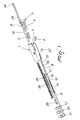
Figure 1 is an exploded perspective view of the locking and recocking assembly with swivel breech-lock and rotating locking head; -
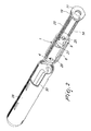
Figure 2 is a perspective view of the locking and recocking assembly in the fully assembled condition, in the position for insertion on its seat, within the sheath or barrel extension; -
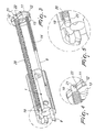
Figure 3 is a partially cutout perspective view of the locking and recocking assembly with the recovery spring and the corresponding guiding pin mounted on the swivel breech-lock; -
Figure 4 is an enlarged view, with respect to the preceding figure, which shows in detail the assembly of the recovery spring guiding pin on the pin anchoring plate; -
Figure 5 is a view, enlarged with respect toFigure 3 , showing in detail the assembly of the recovery spring guiding pin on the swivel breech-lock; -
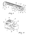
Figure 6 is a perspective view of the locking and recocking assembly mounted on the sheath or barrel extension; -
Figure 7 is a longitudinally sectional perspective view of the locking and recocking assembly mounted on the sheath or barrel extension in the locking position; -
Figure 8 is a partially sectional perspective view of the locking and recocking assembly mounted on the sheath or barrel extension in the opening stroke limit position; -
Figure 9 is a longitudinally sectional perspective view of the locking and recocking assembly illustrating the helical inclined planes provided on the rotating locking head and on the swivel breech-lock; -
Figure 10 is a view, enlarged with respect to the preceding figure, showing in detail a longitudinal cutout of the locking and recocking assembly in which the helical inclined planes cited above are highlighted. - With reference to the cited figures, the locking and recocking assembly with swivel breech-lock and rotating locking head according to the invention comprises a swivel breech-
lock 1 in which a breech-lock recoil spring 2 is inserted and in which a rotatinglocking head 3 is mounted. - The rotating
locking head 3 is jointly connected to the breech-lock 1 by means of ahead rotation pivot 4, which in order to concentrate all the movable mass required for the operation of the weapon on the breech-lock is jointly connected to the breech-lock and engages a helical cam 5 provided on acylindrical shank 6 of the locking head. - This construction of the swivel breech-
lock 1 minimizes the removals of material on the breech-lock and allows to therefore maximize its mass. - An
ejector body 8 is then inserted in a seat 7 which is provided on the swivel breech-lock 1. - A guiding
pin 9, provided at the front with anorientation milling 10, is inserted within theejector body 8. - The guiding
pin 9 is fastened to a spring guidingpin anchoring plate 11 and has, mounted in sequence, adamper 12, in order to cushion the impact of the swivel breech-lock on its stroke limiter, a breech-lock abutment plate 13, on which the stroke of the swivel breech-lock ends during opening, and anejector spring 14. - The
ejector body 8, which is substantially tubular, has in its front portion afront abutment 15 against which, during the opening of the breechblock, the case collides in order to be expelled from the weapon. - The front portion of the
ejector body 8 has arecessed portion 16 which allows the passage of the cartridge during lifting and insertion in the firing chamber. - The
ejector body 8 has, on its rear portion, twotabs lock 1 and prevent its rotation. - The position of the
ejector 8 on the locking and recocking assembly is such that it allows theejector spring 14 to operate also as an auxiliary recovery spring, during the first step of the locking action, and allows the ejector spring guidingpin 9 to guide the cartridge laterally in its step for lifting and insertion into the firing chamber of weapon. - Also on the oscillating breech-
lock 1, a recoveryspring guiding pin 19 is inserted through a hole and therecovery spring 20 is mounted to the rear on a groove and allows the swivel breech-lock 1 to return to the locking position. - As shown more clearly in
Figures 3 and 4 , the recoveryspring guiding pin 19, inserted in the swivel breech-lock 1, passes through the breech-lock abutment plate 13, on which the recovery spring 20 rests. - The recovery
spring guiding pin 19 passes through thedamper 12 and engages, with itsrear end 21, the spring guidingpin anchoring plate 11, by means of therecess 22 of theplate 11 itself. - As shown more clearly in
Figures 3 and 5 , aprotrusion 23, which the recoveryspring guiding pin 19 has on its front side, constitutes, when the pin is engaged on therecess 22, a front coupling of the swivel breech-lock 1 by which the entire locking and recocking assembly is completely assembled, as shown inFigure 2 . - The relative position of the recovery
spring guiding pin 19 is such that when the assembly is mounted, theflat region 24 provided on its front portion allows to use the pin both as a guide for the case, before its ejection, and as an upper abutment for the cartridge during lifting and insertion in the firing chamber. - The recovery
spring guiding pin 19 also acts as a guide for the rotatinglocking head 3 for the entire opening and closing stroke of the swivel breech-lock 1. - A
firing pin 25 is mounted on the swivel breech-lock 1 and, being inserted in thecorresponding spring 26, passes through the rotatinglocking head 3, thehead rotation pivot 4, and the breech-lock. Thefiring pin 25 is jointly connected to the breech-lock by means of astop pin 27. - As shown more clearly in
Figure 2 , the assembled locking and recocking assembly is mounted inside the supporting structure of the weapon, in the specific case of the sheath orbarrel extension 28, orienting and engaging thetab 29 of thehead rotation pivot 4 on aslot 30 which is provided inside the barrel extension. - As shown more clearly in
Figure 6 , a cockingknob 31 is inserted in the assembly and is mounted on the swivel breech-lock 1 through theslot 32 of the sheath orbarrel extension 28. - The
slot 32 is provided at the opening overtravel position of the breech-lock, so that, during normal operation of the weapon, it cannot be disassembled. - As shown more clearly in
Figure 6 , when the entire locking and recocking assembly is completely mounted on the sheath orbarrel extension 28, and coupled thereat by means of a fasteningring 33, both the recoveryspring guiding pin 19 and the ejector spring guidingpin 9 engage, with the respectivefront ends seats springs ejector body 8 and so as to contribute to the guiding of the swivel breech-lock 1 as an aid to thetab 29 of thehead rotation pivot 4 engaged on thecorresponding seat 30 of the sheath or barrel extension 28 (Figure 2 ). - With particular reference to
Figure 7 , when the swivel breech-lock 1 is in the locked position, and also for a substantial extent of the opening stroke, the spring of theejector 14 is not loaded and theejector body 8 is accommodated within the breech-lock. - Starting from a given value of the retraction stroke of the swivel breech-
lock 1, the spring of theejector 14 encounters theejector body 8 and begins to be loaded, pushing it forward until it protrudes from the locking head 3 (Figure 8 ) and strikes the case, which is expelled from the sheath orbarrel extension 28. - During its entire stroke, which is defined by the
tab 18 which engages within aslot 37 of the swivel breech-lock 1 and prevents its rotation (Figure 7 ), theejector body 8 is guided internally by the ejector spring guidingpin 9 and externally by itsother tab 17, which acts on the sheath orbarrel extension 28. - During the opening stroke, the
swivel breechblock 1 compresses both therecovery spring 20, which is guided on thecorresponding pin 19, and theejector spring 14, starting from a certain stroke, thus accumulating the energy required to perform the subsequent locking cycle, as shown schematically inFigures 7 and8 . - With particular reference to
Figure 8 , once the opening stroke has ended, the swivel breech-lock 1 strikes more or less violently, depending on the energy of the fired cartridge, its stroke limit, which is represented by the internal wall of thefastening ring 33, transferring part of the impact energy to thedamper 12, which is interposed between the breech-lock abutment plate 13 and the spring guidingpin anchoring plate 11. - Once the opening stroke has ended, the breech-lock reverses its motion and, biased by the
recovery spring 20 and by theejector spring 14, returns to the closed position, lifting the new cartridge which, being guided laterally by the ejector spring guidingpin 9 and upwardly by the recoveryspring guiding pin 19, is inserted in the firing chamber. - With particular reference to
Figures 9 and 10 , in the last step of the locking stroke of the swivel breech-lock 1, the rotation of theclosing head 3 occurs by means of the contact of an inclinedhelical plane 38 thereof against a corresponding inclinedhelical plane 39 provided on the swivel breech-lock 1. - The contact provides the breech-lock with the speed required to complete the rotation and locking of the
head 3, and also dissipates much of the energy that it has acquired due to the thrust of therecovery spring 20, assisted by theejector spring 14, in the locking stroke. - In this manner, when the locking and recocking assembly is applied to an inertially-actuated weapons system, the swivel breech-
lock 1 arrives, with aplane 40 thereof, in abutment against therecoil spring 2, with an energy which is insufficient to compress it, thus avoiding the elastic reactions of the spring which would otherwise generate a rebound and bouncing motion of the swivel breech-lock 1 during locking. - A locking and recocking assembly with swivel breech-lock and rotating closing head, according to the present invention combines, simply and compactly, in a single assembly and exclusively by way of movable connections, all the components required for the cycle for recocking, locking, opening, case ejection and return to locking required for correct operation of the weapon.
- The disassembly, as shown schematically in
Figure 1 , and assembly, as shown inFigure 2 , can be performed manually, without using tools, providing the mutual couplings exclusively by way of movable connections. - In practice it has been found that the invention achieves the intended aim and objects, combining all the functions of locking, opening, case extraction and ejection, recocking and return to locking in a single locking and recocking assembly which is completely assembled within the sheath or barrel extension of the weapon.
- An important and advantageous feature of the assembly according to the present invention is that it concentrates all the mass required for the inertial operation of the system in a single swivel breech-lock body.
- Another advantage of the present locking and recocking assembly is that the ejector body, with corresponding spring and spring guiding pin, is mounted directly on the swivel breech-lock so that the ejection spring contributes, together with the recovery spring, also to the recocking of the weapon during locking of the breech-lock and simultaneously the spring guiding pin acts as a lateral guide for the cartridge during lifting and insertion in the firing chamber of the weapon.
- Another advantage of the present locking and recocking assembly is that it has the breech-lock recovery spring, and the corresponding spring guiding pin, mounted directly onto the swivel breech-lock so as to be able to use the recovery spring guiding pin both as a guide of the rotating locking head, during the recocking cycle, and as an upper abutment of the cartridge during lifting and subsequent guiding for its insertion in the firing chamber of the weapon.
- Another advantage of the present locking and recocking assembly is that, by means of helical contrast planes provided on the rotating locking head and on the swivel breech-lock, it prevents any bouncing of the breech-lock when, during locking, it abuts against the spring of the inertial system which is interposed between the rotating locking head and the swivel breech-lock.
- Another advantage of the present locking and recocking assembly is the capability of cushioning the impact of the swivel breech-lock on its opening stroke limit by means of the damper which is connected directly to the swivel breech-lock.
- In practice, the present locking and recocking assembly provides a simple and compact system in which all the components in relative motion with respect to the weapon, the inertial mass, the recoil spring, the breech-lock recovery spring, the ejector and the corresponding spring are contained within the sheath or barrel extension of the weapon and move axially with respect to it; this allows to obtain considerable simplifications by eliminating various components, such as the linkage and straps and other minor components needed to connect the swivel breech-lock to the recovery spring which, in the systems of the prior art, is by contrast located within the stock or guide rod of the weapon.
- This application claims the priority of Italian Patent Application No.
MI2007A001474, filed on July 20, 2007
Claims (7)
- A locking and recocking assembly with swivel breech-lock and rotating closing head, particularly for inertially-actuated weapons which use the kinetic energy of recoil, characterized in that it comprises a single body which is inserted in a sheath or barrel extension of a portable weapon, said single body comprising a closure means, for the stable closure of the firing chamber of the weapon, an opening means, a means for expelling the case, and a recocking means with return to locking; said single body being accommodated completely within the supporting structure of the weapon, such as the sheath or barrel extension or breech of the weapon.
- The assembly according to claim 1, characterized in that said single body comprises a swivel breech-lock and all the mass required for inertial operation is concentrated in said swivel breech-lock.
- The assembly according to claim 2, characterized in that said swivel breech-lock comprises a spring of the inertial system and a rotating locking head for locking the firing chamber of the weapon, said rotating head being provided with a helical rotation cam and with helical planes which prevent any bouncing of said swivel breech-lock when, during locking, it abuts against said spring of the inertial system.
- The assembly according to one or more of the preceding claims, characterized in that said case ejection means and said recocking means comprise an ejector, an ejector spring and a spring guiding pin, which are mounted directly on said swivel breech-lock and are adapted to eject the case after firing, during the opening of the weapon and simultaneously with a lateral guide of the cartridge during lifting and insertion in the firing chamber of the weapon, and to perform the locking return of said assembly.
- The assembly according to one or more of the preceding claims, characterized in that it comprises a recovery spring and a recovery spring guiding pin, which are mounted directly on said swivel breech-lock and are adapted to provide for the return of said breech-lock to the locking position, after the step for opening and ejecting the case, and for guiding said cartridge upwardly, during lifting and insertion in the firing chamber of the weapon; said recovery spring guiding pin acting as a guide for the case before its expulsion; said recovery spring guiding pin acting as a guide for the rotating locking head throughout the opening and locking stroke of the swivel breech-lock.
- The assembly according to one or more of the preceding claims, characterized in that it comprises a damper which is connected directly to said swivel breech-lock and is suitable to cushion the impact of said breech-lock against its opening stroke limit.
- The assembly according to one or more of the preceding claims, characterized in that said single body can be inserted and extracted in said sheath or barrel extension without using tools.
Applications Claiming Priority (1)
| Application Number | Priority Date | Filing Date | Title |
|---|---|---|---|
| IT001474A ITMI20071474A1 (en) | 2007-07-20 | 2007-07-20 | CLOSING AND RESET UNIT WITH OSCILLATING SHUTTER AND ROTARY CLOSING HEAD, PARTICULARLY FOR WEAPONS WITH INERTIAL OPERATION USING THE KINETIC ENERGY OF RINCULO |
Publications (3)
| Publication Number | Publication Date |
|---|---|
| EP2017565A2 true EP2017565A2 (en) | 2009-01-21 |
| EP2017565A3 EP2017565A3 (en) | 2015-04-08 |
| EP2017565B1 EP2017565B1 (en) | 2018-08-29 |
Family
ID=39865463
Family Applications (1)
| Application Number | Title | Priority Date | Filing Date |
|---|---|---|---|
| EP08012289.8A Active EP2017565B1 (en) | 2007-07-20 | 2008-07-08 | Locking and recocking assembly with swivel breech-lock and rotating locking head, particularly for inertially-actuated weapons using the kinetic energy of recoil |
Country Status (10)
| Country | Link |
|---|---|
| US (1) | US7878107B2 (en) |
| EP (1) | EP2017565B1 (en) |
| JP (1) | JP5334479B2 (en) |
| CN (1) | CN101482380B (en) |
| BR (1) | BRPI0803524B1 (en) |
| EA (1) | EA014565B1 (en) |
| ES (1) | ES2698420T3 (en) |
| IL (1) | IL192753A (en) |
| IT (1) | ITMI20071474A1 (en) |
| MX (1) | MX2008009338A (en) |
Cited By (2)
| Publication number | Priority date | Publication date | Assignee | Title |
|---|---|---|---|---|
| WO2018117990A1 (en) * | 2016-12-23 | 2018-06-28 | Bahtiyar Tasyagan | Recoil-operated breech mechanism comprising a bolt carrier and rotatable bolt, and providing convenience in assembly-disassembly |
| CZ308781B6 (en) * | 2021-01-08 | 2021-05-12 | Česká Zbrojovka A.S. | Assembly of the closure, the body of the closure and the ejector |
Families Citing this family (13)
| Publication number | Priority date | Publication date | Assignee | Title |
|---|---|---|---|---|
| US8505227B2 (en) | 2009-03-24 | 2013-08-13 | Sturm, Ruger & Company, Inc. | Firearm with quick coupling barrel interlock system |
| US8479429B2 (en) | 2009-03-24 | 2013-07-09 | Sturm, Ruger & Company, Inc. | Firearm with quick coupling barrel system |
| US9057576B2 (en) | 2009-03-24 | 2015-06-16 | Sturm, Ruger & Company, Inc. | Firearm with quick coupling barrel system |
| US8490312B2 (en) | 2009-03-24 | 2013-07-23 | Sturm, Ruger & Company, Inc. | Quick coupling barrel system for firearm |
| US8356543B2 (en) | 2009-10-02 | 2013-01-22 | Defense Deisigns, LLC | Firearm firing mechanism |
| KR101147975B1 (en) | 2010-04-27 | 2012-05-24 | 태성정밀공업 주식회사 | Rope for carrying something anchor for musical instrument |
| US9488423B2 (en) | 2011-01-14 | 2016-11-08 | Arm West, Llc | Firearm systems and methods |
| AR104686A1 (en) * | 2015-05-22 | 2017-08-09 | Arm West Llc | FIREARM SYSTEMS AND METHODS |
| DE102015008797A1 (en) * | 2015-07-10 | 2017-01-12 | Rheinmetall Waffe Munition Gmbh | Case ejection device |
| US11569605B2 (en) | 2016-12-20 | 2023-01-31 | Te Connectivity Germany Gmbh | Contact device and contact system |
| US10677547B2 (en) | 2018-01-09 | 2020-06-09 | Sturm, Ruger & Company, Inc. | Pump action firearm with slide lock mechanism |
| US11098972B2 (en) * | 2018-03-20 | 2021-08-24 | Taylor. Weapons, Inc. | Recoil system for a self-loading firearm |
| US11549769B1 (en) * | 2019-07-31 | 2023-01-10 | Mark John Roth | Self-locking bolt system not requiring an external surface to lock to |
Citations (8)
| Publication number | Priority date | Publication date | Assignee | Title |
|---|---|---|---|---|
| US3447417A (en) * | 1966-03-09 | 1969-06-03 | Benelli Spa | Gun with a floating breech bolt |
| US3653140A (en) * | 1970-05-04 | 1972-04-04 | Remington Arms Co Inc | Firearm receiver mechanism with a roller detent pin for a telescopic breech-bolt |
| EP0128125A2 (en) * | 1983-05-09 | 1984-12-12 | BENELLI ARMI S.p.A. | Bolt assembly with a rotating locking bolt head and a floating bolt element for automatic firearms |
| EP0281793A2 (en) * | 1987-03-12 | 1988-09-14 | BENELLI ARMI S.p.A. | Cartridge feeding assembly for smooth-bore guns with semi-automatic or pump operation |
| EP0329797A1 (en) * | 1987-12-29 | 1989-08-30 | Renaud Kerbrat | Device for retarding the opening or locking action of a mobile firearm breech block |
| US20050066564A1 (en) * | 2003-05-23 | 2005-03-31 | Ra Brands, L.L.C. | Bolt assembly with locking system |
| US20050223613A1 (en) * | 2003-01-27 | 2005-10-13 | Terrence Bender | Gas operated action for auto-loading firearms |
| EP1645832A1 (en) * | 2004-10-06 | 2006-04-12 | Fabbrica d'Armi Pietro Beretta S.p.A. | Firearm with selection device for right or left-hand cartridge case ejection |
Family Cites Families (12)
| Publication number | Priority date | Publication date | Assignee | Title |
|---|---|---|---|---|
| US2645873A (en) * | 1950-01-31 | 1953-07-21 | Remington Arms Co Inc | Slide-actuated firearm with tilting locking block |
| US3967403A (en) * | 1975-01-22 | 1976-07-06 | The United States Of America As Represented By The Secretary Of The Army | Manually-operated firearm with forward-moving barrel and automatic breech lock |
| SE427580B (en) * | 1979-04-11 | 1983-04-18 | Aimpoint Ab | DEVICE WITH ELECTRIC WEAPON WITH PIPE AND END PIECE |
| JPS56500579A (en) * | 1979-04-11 | 1981-04-30 | ||
| US4615132A (en) * | 1983-03-28 | 1986-10-07 | Smith David E | Self loading pistol having a rear sight which secures a detachable breech block insert |
| RU2066820C1 (en) * | 1993-06-28 | 1996-09-20 | Государственное предприятие "Ижевский механический завод" | Magazine gun bolt mechanism |
| US5651205A (en) * | 1996-03-29 | 1997-07-29 | Sturm, Ruger & Company, Inc. | Bolt and firing pin locking system for firearm |
| PL185081B1 (en) * | 1997-07-24 | 2003-02-28 | Otkrytoe Aktsionernoe Obschest | Automatic weapon - storming rifle of kalashnikov type |
| US6484430B1 (en) * | 1999-01-27 | 2002-11-26 | Zdf Import/Export, Inc. | Multi-lugged bolt carrier and barrel for rifles |
| CA2535659C (en) * | 2003-08-11 | 2011-01-18 | Fats, Inc. | Locking assembly for firearm simulators |
| US7971379B2 (en) * | 2004-02-13 | 2011-07-05 | Rmdi, Llc | Firearm |
| BE1016821A3 (en) * | 2005-10-25 | 2007-07-03 | Browning Int Sa | IMPROVED SEMI-AUTOMATIC RIFLE |
-
2007
- 2007-07-20 IT IT001474A patent/ITMI20071474A1/en unknown
-
2008
- 2008-07-08 EP EP08012289.8A patent/EP2017565B1/en active Active
- 2008-07-08 ES ES08012289T patent/ES2698420T3/en active Active
- 2008-07-08 US US12/217,765 patent/US7878107B2/en active Active
- 2008-07-10 IL IL192753A patent/IL192753A/en active IP Right Grant
- 2008-07-18 CN CN2008101756631A patent/CN101482380B/en active Active
- 2008-07-18 JP JP2008187632A patent/JP5334479B2/en active Active
- 2008-07-18 EA EA200801578A patent/EA014565B1/en unknown
- 2008-07-18 MX MX2008009338A patent/MX2008009338A/en active IP Right Grant
- 2008-07-21 BR BRPI0803524-5A patent/BRPI0803524B1/en active IP Right Grant
Patent Citations (8)
| Publication number | Priority date | Publication date | Assignee | Title |
|---|---|---|---|---|
| US3447417A (en) * | 1966-03-09 | 1969-06-03 | Benelli Spa | Gun with a floating breech bolt |
| US3653140A (en) * | 1970-05-04 | 1972-04-04 | Remington Arms Co Inc | Firearm receiver mechanism with a roller detent pin for a telescopic breech-bolt |
| EP0128125A2 (en) * | 1983-05-09 | 1984-12-12 | BENELLI ARMI S.p.A. | Bolt assembly with a rotating locking bolt head and a floating bolt element for automatic firearms |
| EP0281793A2 (en) * | 1987-03-12 | 1988-09-14 | BENELLI ARMI S.p.A. | Cartridge feeding assembly for smooth-bore guns with semi-automatic or pump operation |
| EP0329797A1 (en) * | 1987-12-29 | 1989-08-30 | Renaud Kerbrat | Device for retarding the opening or locking action of a mobile firearm breech block |
| US20050223613A1 (en) * | 2003-01-27 | 2005-10-13 | Terrence Bender | Gas operated action for auto-loading firearms |
| US20050066564A1 (en) * | 2003-05-23 | 2005-03-31 | Ra Brands, L.L.C. | Bolt assembly with locking system |
| EP1645832A1 (en) * | 2004-10-06 | 2006-04-12 | Fabbrica d'Armi Pietro Beretta S.p.A. | Firearm with selection device for right or left-hand cartridge case ejection |
Cited By (2)
| Publication number | Priority date | Publication date | Assignee | Title |
|---|---|---|---|---|
| WO2018117990A1 (en) * | 2016-12-23 | 2018-06-28 | Bahtiyar Tasyagan | Recoil-operated breech mechanism comprising a bolt carrier and rotatable bolt, and providing convenience in assembly-disassembly |
| CZ308781B6 (en) * | 2021-01-08 | 2021-05-12 | Česká Zbrojovka A.S. | Assembly of the closure, the body of the closure and the ejector |
Also Published As
| Publication number | Publication date |
|---|---|
| IL192753A0 (en) | 2009-08-03 |
| BRPI0803524B1 (en) | 2020-10-20 |
| US7878107B2 (en) | 2011-02-01 |
| CN101482380A (en) | 2009-07-15 |
| JP2009041902A (en) | 2009-02-26 |
| EP2017565A3 (en) | 2015-04-08 |
| BRPI0803524A2 (en) | 2009-08-25 |
| MX2008009338A (en) | 2009-03-05 |
| US20090019754A1 (en) | 2009-01-22 |
| CN101482380B (en) | 2013-09-25 |
| IL192753A (en) | 2012-03-29 |
| EP2017565B1 (en) | 2018-08-29 |
| EA200801578A1 (en) | 2009-02-27 |
| ES2698420T3 (en) | 2019-02-04 |
| EA014565B1 (en) | 2010-12-30 |
| JP5334479B2 (en) | 2013-11-06 |
| ITMI20071474A1 (en) | 2009-01-21 |
Similar Documents
| Publication | Publication Date | Title |
|---|---|---|
| US7878107B2 (en) | Locking and recocking assembly with swivel breech-lock and rotating locking head, particularly for inertially-actuated weapons using the kinetic energy of recoil | |
| US9874417B2 (en) | Firing control system for firearm | |
| US10113830B2 (en) | Pump-action firearm with bolt carrier locking mechanism and folding butt stock | |
| CN1758010B (en) | Firearm with selection device for right or left-hand cartridge case ejection | |
| CA2173589C (en) | Blank firing conversions for semiautomatic pistols | |
| EP2017564B1 (en) | Modular portable weapon | |
| US5736667A (en) | Automatic firearm arranged for high safety and rapid dismantling | |
| US4677897A (en) | Anti-armor gun | |
| US4015512A (en) | Gas-operated firearm | |
| US11815325B2 (en) | Breechblock of a weapon system and weapon system with the breechblock | |
| US10281225B2 (en) | Self-loading pistol with selective slide lock delaying the opening movement during firing but facilitating manual cocking | |
| US7568422B1 (en) | Bolt operation facility for autoloading firearm | |
| US4467698A (en) | Angular shape firing pin for use with a collapsible toggle recoil in a hand held weapon | |
| US6595100B2 (en) | Weapon | |
| EP3364143B1 (en) | Bolt stop shock absorber for gun | |
| US10001336B2 (en) | Auto sear actuation linkage for compact AR-platform firearm | |
| AU2016243800A1 (en) | Forward ejection system of casing | |
| EP2392888B1 (en) | Firing actuator mechanism for toy gun | |
| US20100223830A1 (en) | Linear bolt mechanism for a gun | |
| CZ2005799A3 (en) | Self-loading weapon with locked breech mechanism | |
| EP0910782B1 (en) | Barrel positioning mechanism for automatic firearms | |
| WO2023061789A1 (en) | Firearm | |
| WO2023061790A1 (en) | Firearm |
Legal Events
| Date | Code | Title | Description |
|---|---|---|---|
| PUAI | Public reference made under article 153(3) epc to a published international application that has entered the european phase |
Free format text: ORIGINAL CODE: 0009012 |
|
| AK | Designated contracting states |
Kind code of ref document: A2 Designated state(s): AT BE BG CH CY CZ DE DK EE ES FI FR GB GR HR HU IE IS IT LI LT LU LV MC MT NL NO PL PT RO SE SI SK TR |
|
| AX | Request for extension of the european patent |
Extension state: AL BA MK RS |
|
| REG | Reference to a national code |
Ref country code: HK Ref legal event code: DE Ref document number: 1123350 Country of ref document: HK |
|
| PUAL | Search report despatched |
Free format text: ORIGINAL CODE: 0009013 |
|
| AK | Designated contracting states |
Kind code of ref document: A3 Designated state(s): AT BE BG CH CY CZ DE DK EE ES FI FR GB GR HR HU IE IS IT LI LT LU LV MC MT NL NO PL PT RO SE SI SK TR |
|
| AX | Request for extension of the european patent |
Extension state: AL BA MK RS |
|
| RIC1 | Information provided on ipc code assigned before grant |
Ipc: F41A 25/12 20060101ALI20150305BHEP Ipc: F41A 3/72 20060101ALI20150305BHEP Ipc: F41A 3/26 20060101AFI20150305BHEP Ipc: F41A 15/14 20060101ALI20150305BHEP Ipc: F41A 15/16 20060101ALI20150305BHEP |
|
| 17P | Request for examination filed |
Effective date: 20150910 |
|
| RBV | Designated contracting states (corrected) |
Designated state(s): AT BE BG CH CY CZ DE DK EE ES FI FR GB GR HR HU IE IS IT LI LT LU LV MC MT NL NO PL PT RO SE SI SK TR |
|
| AKX | Designation fees paid |
Designated state(s): AT BE BG CH CY CZ DE DK EE ES FI FR GB GR HR HU IE IS IT LI LT LU LV MC MT NL NO PL PT RO SE SI SK TR |
|
| AXX | Extension fees paid |
Extension state: BA Extension state: AL Extension state: MK Extension state: RS |
|
| 17Q | First examination report despatched |
Effective date: 20160620 |
|
| STAA | Information on the status of an ep patent application or granted ep patent |
Free format text: STATUS: EXAMINATION IS IN PROGRESS |
|
| GRAP | Despatch of communication of intention to grant a patent |
Free format text: ORIGINAL CODE: EPIDOSNIGR1 |
|
| STAA | Information on the status of an ep patent application or granted ep patent |
Free format text: STATUS: GRANT OF PATENT IS INTENDED |
|
| INTG | Intention to grant announced |
Effective date: 20171222 |
|
| GRAJ | Information related to disapproval of communication of intention to grant by the applicant or resumption of examination proceedings by the epo deleted |
Free format text: ORIGINAL CODE: EPIDOSDIGR1 |
|
| STAA | Information on the status of an ep patent application or granted ep patent |
Free format text: STATUS: EXAMINATION IS IN PROGRESS |
|
| GRAS | Grant fee paid |
Free format text: ORIGINAL CODE: EPIDOSNIGR3 |
|
| STAA | Information on the status of an ep patent application or granted ep patent |
Free format text: STATUS: GRANT OF PATENT IS INTENDED |
|
| GRAP | Despatch of communication of intention to grant a patent |
Free format text: ORIGINAL CODE: EPIDOSNIGR1 |
|
| INTC | Intention to grant announced (deleted) | ||
| INTG | Intention to grant announced |
Effective date: 20180504 |
|
| GRAA | (expected) grant |
Free format text: ORIGINAL CODE: 0009210 |
|
| STAA | Information on the status of an ep patent application or granted ep patent |
Free format text: STATUS: THE PATENT HAS BEEN GRANTED |
|
| AK | Designated contracting states |
Kind code of ref document: B1 Designated state(s): AT BE BG CH CY CZ DE DK EE ES FI FR GB GR HR HU IE IS IT LI LT LU LV MC MT NL NO PL PT RO SE SI SK TR |
|
| REG | Reference to a national code |
Ref country code: GB Ref legal event code: FG4D |
|
| REG | Reference to a national code |
Ref country code: CH Ref legal event code: EP |
|
| REG | Reference to a national code |
Ref country code: AT Ref legal event code: REF Ref document number: 1035619 Country of ref document: AT Kind code of ref document: T Effective date: 20180915 |
|
| REG | Reference to a national code |
Ref country code: IE Ref legal event code: FG4D |
|
| REG | Reference to a national code |
Ref country code: DE Ref legal event code: R096 Ref document number: 602008056666 Country of ref document: DE |
|
| REG | Reference to a national code |
Ref country code: NL Ref legal event code: MP Effective date: 20180829 |
|
| REG | Reference to a national code |
Ref country code: LT Ref legal event code: MG4D |
|
| PG25 | Lapsed in a contracting state [announced via postgrant information from national office to epo] |
Ref country code: NL Free format text: LAPSE BECAUSE OF FAILURE TO SUBMIT A TRANSLATION OF THE DESCRIPTION OR TO PAY THE FEE WITHIN THE PRESCRIBED TIME-LIMIT Effective date: 20180829 Ref country code: BG Free format text: LAPSE BECAUSE OF FAILURE TO SUBMIT A TRANSLATION OF THE DESCRIPTION OR TO PAY THE FEE WITHIN THE PRESCRIBED TIME-LIMIT Effective date: 20181129 Ref country code: LT Free format text: LAPSE BECAUSE OF FAILURE TO SUBMIT A TRANSLATION OF THE DESCRIPTION OR TO PAY THE FEE WITHIN THE PRESCRIBED TIME-LIMIT Effective date: 20180829 Ref country code: GR Free format text: LAPSE BECAUSE OF FAILURE TO SUBMIT A TRANSLATION OF THE DESCRIPTION OR TO PAY THE FEE WITHIN THE PRESCRIBED TIME-LIMIT Effective date: 20181130 Ref country code: IS Free format text: LAPSE BECAUSE OF FAILURE TO SUBMIT A TRANSLATION OF THE DESCRIPTION OR TO PAY THE FEE WITHIN THE PRESCRIBED TIME-LIMIT Effective date: 20181229 Ref country code: SE Free format text: LAPSE BECAUSE OF FAILURE TO SUBMIT A TRANSLATION OF THE DESCRIPTION OR TO PAY THE FEE WITHIN THE PRESCRIBED TIME-LIMIT Effective date: 20180829 Ref country code: NO Free format text: LAPSE BECAUSE OF FAILURE TO SUBMIT A TRANSLATION OF THE DESCRIPTION OR TO PAY THE FEE WITHIN THE PRESCRIBED TIME-LIMIT Effective date: 20181129 Ref country code: FI Free format text: LAPSE BECAUSE OF FAILURE TO SUBMIT A TRANSLATION OF THE DESCRIPTION OR TO PAY THE FEE WITHIN THE PRESCRIBED TIME-LIMIT Effective date: 20180829 |
|
| REG | Reference to a national code |
Ref country code: ES Ref legal event code: FG2A Ref document number: 2698420 Country of ref document: ES Kind code of ref document: T3 Effective date: 20190204 |
|
| REG | Reference to a national code |
Ref country code: AT Ref legal event code: MK05 Ref document number: 1035619 Country of ref document: AT Kind code of ref document: T Effective date: 20180829 |
|
| PG25 | Lapsed in a contracting state [announced via postgrant information from national office to epo] |
Ref country code: HR Free format text: LAPSE BECAUSE OF FAILURE TO SUBMIT A TRANSLATION OF THE DESCRIPTION OR TO PAY THE FEE WITHIN THE PRESCRIBED TIME-LIMIT Effective date: 20180829 Ref country code: LV Free format text: LAPSE BECAUSE OF FAILURE TO SUBMIT A TRANSLATION OF THE DESCRIPTION OR TO PAY THE FEE WITHIN THE PRESCRIBED TIME-LIMIT Effective date: 20180829 |
|
| PG25 | Lapsed in a contracting state [announced via postgrant information from national office to epo] |
Ref country code: PL Free format text: LAPSE BECAUSE OF FAILURE TO SUBMIT A TRANSLATION OF THE DESCRIPTION OR TO PAY THE FEE WITHIN THE PRESCRIBED TIME-LIMIT Effective date: 20180829 Ref country code: EE Free format text: LAPSE BECAUSE OF FAILURE TO SUBMIT A TRANSLATION OF THE DESCRIPTION OR TO PAY THE FEE WITHIN THE PRESCRIBED TIME-LIMIT Effective date: 20180829 Ref country code: AT Free format text: LAPSE BECAUSE OF FAILURE TO SUBMIT A TRANSLATION OF THE DESCRIPTION OR TO PAY THE FEE WITHIN THE PRESCRIBED TIME-LIMIT Effective date: 20180829 Ref country code: CZ Free format text: LAPSE BECAUSE OF FAILURE TO SUBMIT A TRANSLATION OF THE DESCRIPTION OR TO PAY THE FEE WITHIN THE PRESCRIBED TIME-LIMIT Effective date: 20180829 Ref country code: RO Free format text: LAPSE BECAUSE OF FAILURE TO SUBMIT A TRANSLATION OF THE DESCRIPTION OR TO PAY THE FEE WITHIN THE PRESCRIBED TIME-LIMIT Effective date: 20180829 |
|
| PG25 | Lapsed in a contracting state [announced via postgrant information from national office to epo] |
Ref country code: SK Free format text: LAPSE BECAUSE OF FAILURE TO SUBMIT A TRANSLATION OF THE DESCRIPTION OR TO PAY THE FEE WITHIN THE PRESCRIBED TIME-LIMIT Effective date: 20180829 Ref country code: DK Free format text: LAPSE BECAUSE OF FAILURE TO SUBMIT A TRANSLATION OF THE DESCRIPTION OR TO PAY THE FEE WITHIN THE PRESCRIBED TIME-LIMIT Effective date: 20180829 |
|
| REG | Reference to a national code |
Ref country code: DE Ref legal event code: R097 Ref document number: 602008056666 Country of ref document: DE |
|
| PLBE | No opposition filed within time limit |
Free format text: ORIGINAL CODE: 0009261 |
|
| STAA | Information on the status of an ep patent application or granted ep patent |
Free format text: STATUS: NO OPPOSITION FILED WITHIN TIME LIMIT |
|
| 26N | No opposition filed |
Effective date: 20190531 |
|
| PG25 | Lapsed in a contracting state [announced via postgrant information from national office to epo] |
Ref country code: SI Free format text: LAPSE BECAUSE OF FAILURE TO SUBMIT A TRANSLATION OF THE DESCRIPTION OR TO PAY THE FEE WITHIN THE PRESCRIBED TIME-LIMIT Effective date: 20180829 |
|
| PG25 | Lapsed in a contracting state [announced via postgrant information from national office to epo] |
Ref country code: MC Free format text: LAPSE BECAUSE OF FAILURE TO SUBMIT A TRANSLATION OF THE DESCRIPTION OR TO PAY THE FEE WITHIN THE PRESCRIBED TIME-LIMIT Effective date: 20180829 |
|
| REG | Reference to a national code |
Ref country code: CH Ref legal event code: PL |
|
| REG | Reference to a national code |
Ref country code: BE Ref legal event code: MM Effective date: 20190731 |
|
| PG25 | Lapsed in a contracting state [announced via postgrant information from national office to epo] |
Ref country code: BE Free format text: LAPSE BECAUSE OF NON-PAYMENT OF DUE FEES Effective date: 20190731 Ref country code: LI Free format text: LAPSE BECAUSE OF NON-PAYMENT OF DUE FEES Effective date: 20190731 Ref country code: CH Free format text: LAPSE BECAUSE OF NON-PAYMENT OF DUE FEES Effective date: 20190731 Ref country code: LU Free format text: LAPSE BECAUSE OF NON-PAYMENT OF DUE FEES Effective date: 20190708 |
|
| PG25 | Lapsed in a contracting state [announced via postgrant information from national office to epo] |
Ref country code: PT Free format text: LAPSE BECAUSE OF FAILURE TO SUBMIT A TRANSLATION OF THE DESCRIPTION OR TO PAY THE FEE WITHIN THE PRESCRIBED TIME-LIMIT Effective date: 20181229 |
|
| PG25 | Lapsed in a contracting state [announced via postgrant information from national office to epo] |
Ref country code: IE Free format text: LAPSE BECAUSE OF NON-PAYMENT OF DUE FEES Effective date: 20190708 |
|
| PG25 | Lapsed in a contracting state [announced via postgrant information from national office to epo] |
Ref country code: CY Free format text: LAPSE BECAUSE OF FAILURE TO SUBMIT A TRANSLATION OF THE DESCRIPTION OR TO PAY THE FEE WITHIN THE PRESCRIBED TIME-LIMIT Effective date: 20180829 |
|
| PG25 | Lapsed in a contracting state [announced via postgrant information from national office to epo] |
Ref country code: MT Free format text: LAPSE BECAUSE OF FAILURE TO SUBMIT A TRANSLATION OF THE DESCRIPTION OR TO PAY THE FEE WITHIN THE PRESCRIBED TIME-LIMIT Effective date: 20180829 Ref country code: HU Free format text: LAPSE BECAUSE OF FAILURE TO SUBMIT A TRANSLATION OF THE DESCRIPTION OR TO PAY THE FEE WITHIN THE PRESCRIBED TIME-LIMIT; INVALID AB INITIO Effective date: 20080708 |
|
| P01 | Opt-out of the competence of the unified patent court (upc) registered |
Effective date: 20230530 |
|
| PGFP | Annual fee paid to national office [announced via postgrant information from national office to epo] |
Ref country code: IT Payment date: 20230525 Year of fee payment: 16 Ref country code: FR Payment date: 20230606 Year of fee payment: 16 |
|
| PGFP | Annual fee paid to national office [announced via postgrant information from national office to epo] |
Ref country code: TR Payment date: 20230616 Year of fee payment: 16 |
|
| PGFP | Annual fee paid to national office [announced via postgrant information from national office to epo] |
Ref country code: GB Payment date: 20230606 Year of fee payment: 16 Ref country code: ES Payment date: 20230922 Year of fee payment: 16 |
|
| PGFP | Annual fee paid to national office [announced via postgrant information from national office to epo] |
Ref country code: DE Payment date: 20230629 Year of fee payment: 16 |