BRPI0803524B1 - locking and re-cocking set, with pivoting breech lock and rotating closing head - Google Patents
locking and re-cocking set, with pivoting breech lock and rotating closing head Download PDFInfo
- Publication number
- BRPI0803524B1 BRPI0803524B1 BRPI0803524-5A BRPI0803524A BRPI0803524B1 BR PI0803524 B1 BRPI0803524 B1 BR PI0803524B1 BR PI0803524 A BRPI0803524 A BR PI0803524A BR PI0803524 B1 BRPI0803524 B1 BR PI0803524B1
- Authority
- BR
- Brazil
- Prior art keywords
- locking
- breech lock
- weapon
- spring
- pivoting
- Prior art date
Links
- 239000002775 capsule Substances 0.000 claims abstract description 16
- 238000011084 recovery Methods 0.000 claims description 33
- 238000010304 firing Methods 0.000 claims description 20
- 238000003780 insertion Methods 0.000 claims description 10
- 230000037431 insertion Effects 0.000 claims description 10
- 239000006096 absorbing agent Substances 0.000 claims description 5
- 230000035939 shock Effects 0.000 claims description 5
- 230000000694 effects Effects 0.000 claims description 2
- 230000008878 coupling Effects 0.000 description 3
- 238000010168 coupling process Methods 0.000 description 3
- 238000005859 coupling reaction Methods 0.000 description 3
- 238000006243 chemical reaction Methods 0.000 description 2
- 239000012141 concentrate Substances 0.000 description 2
- 230000006835 compression Effects 0.000 description 1
- 238000007906 compression Methods 0.000 description 1
- 238000010276 construction Methods 0.000 description 1
- 239000000463 material Substances 0.000 description 1
- 235000013372 meat Nutrition 0.000 description 1
- 238000000034 method Methods 0.000 description 1
- 238000003801 milling Methods 0.000 description 1
- 238000009964 serging Methods 0.000 description 1
Images


Classifications
-
- F—MECHANICAL ENGINEERING; LIGHTING; HEATING; WEAPONS; BLASTING
- F41—WEAPONS
- F41A—FUNCTIONAL FEATURES OR DETAILS COMMON TO BOTH SMALLARMS AND ORDNANCE, e.g. CANNONS; MOUNTINGS FOR SMALLARMS OR ORDNANCE
- F41A3/00—Breech mechanisms, e.g. locks
- F41A3/12—Bolt action, i.e. the main breech opening movement being parallel to the barrel axis
- F41A3/14—Rigid bolt locks, i.e. having locking elements rigidly mounted on the bolt or bolt handle and on the barrel or breech-housing respectively
- F41A3/16—Rigid bolt locks, i.e. having locking elements rigidly mounted on the bolt or bolt handle and on the barrel or breech-housing respectively the locking elements effecting a rotary movement about the barrel axis, e.g. rotating cylinder bolt locks
- F41A3/26—Rigid bolt locks, i.e. having locking elements rigidly mounted on the bolt or bolt handle and on the barrel or breech-housing respectively the locking elements effecting a rotary movement about the barrel axis, e.g. rotating cylinder bolt locks semi-automatically or automatically operated, e.g. having a slidable bolt-carrier and a rotatable bolt
-
- F—MECHANICAL ENGINEERING; LIGHTING; HEATING; WEAPONS; BLASTING
- F41—WEAPONS
- F41A—FUNCTIONAL FEATURES OR DETAILS COMMON TO BOTH SMALLARMS AND ORDNANCE, e.g. CANNONS; MOUNTINGS FOR SMALLARMS OR ORDNANCE
- F41A15/00—Cartridge extractors, i.e. devices for pulling cartridges or cartridge cases at least partially out of the cartridge chamber; Cartridge ejectors, i.e. devices for throwing the extracted cartridges or cartridge cases free of the gun
- F41A15/12—Cartridge extractors, i.e. devices for pulling cartridges or cartridge cases at least partially out of the cartridge chamber; Cartridge ejectors, i.e. devices for throwing the extracted cartridges or cartridge cases free of the gun for bolt-action guns
- F41A15/14—Cartridge extractors, i.e. devices for pulling cartridges or cartridge cases at least partially out of the cartridge chamber; Cartridge ejectors, i.e. devices for throwing the extracted cartridges or cartridge cases free of the gun for bolt-action guns the ejector being mounted on or within the bolt; Extractors per se
-
- F—MECHANICAL ENGINEERING; LIGHTING; HEATING; WEAPONS; BLASTING
- F41—WEAPONS
- F41A—FUNCTIONAL FEATURES OR DETAILS COMMON TO BOTH SMALLARMS AND ORDNANCE, e.g. CANNONS; MOUNTINGS FOR SMALLARMS OR ORDNANCE
- F41A15/00—Cartridge extractors, i.e. devices for pulling cartridges or cartridge cases at least partially out of the cartridge chamber; Cartridge ejectors, i.e. devices for throwing the extracted cartridges or cartridge cases free of the gun
- F41A15/12—Cartridge extractors, i.e. devices for pulling cartridges or cartridge cases at least partially out of the cartridge chamber; Cartridge ejectors, i.e. devices for throwing the extracted cartridges or cartridge cases free of the gun for bolt-action guns
- F41A15/16—Cartridge extractors, i.e. devices for pulling cartridges or cartridge cases at least partially out of the cartridge chamber; Cartridge ejectors, i.e. devices for throwing the extracted cartridges or cartridge cases free of the gun for bolt-action guns the ejector being mounted on the breech housing or frame
-
- F—MECHANICAL ENGINEERING; LIGHTING; HEATING; WEAPONS; BLASTING
- F41—WEAPONS
- F41A—FUNCTIONAL FEATURES OR DETAILS COMMON TO BOTH SMALLARMS AND ORDNANCE, e.g. CANNONS; MOUNTINGS FOR SMALLARMS OR ORDNANCE
- F41A25/00—Gun mountings permitting recoil or return to battery, e.g. gun cradles; Barrel buffers or brakes
- F41A25/10—Spring-operated systems
- F41A25/12—Spring-operated systems using coil springs
-
- F—MECHANICAL ENGINEERING; LIGHTING; HEATING; WEAPONS; BLASTING
- F41—WEAPONS
- F41A—FUNCTIONAL FEATURES OR DETAILS COMMON TO BOTH SMALLARMS AND ORDNANCE, e.g. CANNONS; MOUNTINGS FOR SMALLARMS OR ORDNANCE
- F41A3/00—Breech mechanisms, e.g. locks
- F41A3/64—Mounting of breech-blocks; Accessories for breech-blocks or breech-block mountings
- F41A3/72—Operating handles or levers; Mounting thereof in breech-blocks or bolts
Abstract
CONJUNTO DE TRAVAR E RE-ENGATILHAR, COM TRAVA DE CULATRA PIVOTANTE E CABEÇA DE FECHAMENTO ROTATIVA. Conjunto de travar e re-engatilhar, com trava de culatra pivotante e cabeça de fechamento rotativa particularmente projetadas para armas inercialmente atuadas, que combina, em um conjunto único, todas as funções de travar, abrir, ejeção de cápsula e re-engatilhar com retomo de travamento, necessárias para a correta operação da arma; essas funções eram, até agora, conferidas a vários componentes montados de forma variável na arma. O conjunto de travar e re-engatilhar, com trava de culatra pivotante e cabeça de fechamento rotativa tem todos os meios, necessários para a operação inercial, concentrados na trava de culatra pivotante, que é acomodada completamente dentro da estrutura de suporte da arma, como a bainha ou extensão do tambor ou culatra da arma. Tudo isto leva a melhor balanceamento e estabilidade da arma, maior confiabilidade na operação, maior simplicidade construtiva e facilidade de montagem e desmontagem.LOCK AND RE-COILING SET, WITH PIVOTING CULATRA LOCK AND ROTATING CLOSING HEAD. Locking and re-cocking set, with pivoting breech lock and rotating closing head particularly designed for inertially acted weapons, which combines, in a single set, all the functions of locking, opening, capsule ejection and re-cocking with return locking, necessary for the correct operation of the weapon; these functions were, until now, assigned to various components mounted in a variable manner on the weapon. The locking and re-cocking assembly, with pivoting breech lock and rotating closing head, has all the means necessary for inertial operation, concentrated in the pivoting breech lock, which is completely accommodated within the weapon support structure, as the barrel or extension of the barrel or breech of the weapon. All of this leads to better balance and stability of the weapon, greater reliability in operation, greater constructive simplicity and ease of assembly and disassembly.
Description
[001] A presente invenção refere-se a um conjunto de travar e reengatilhar, com trava de culatra pivotante e cabeça de fechamento rotativa, particularmente para armas inercialmente atuadas que usam a energia cinética de recuo.[001] The present invention relates to a set of locking and re-cocking, with pivoting breech lock and rotating closing head, particularly for inertially acted weapons that use the kinetic energy of recoil.
[002] Armas inercialmente atuadas são de há muito conhecidas, nas quais o recuo da arma é usado para armazenar energia por meio da compressão de uma mola que é interposta entre a culatra e a cabeça de travamento e explorar a reação como força para várias operações do ciclo de re-engatilhar: fechamento, abertura, extração e expulsão de cápsula, armar o gatilho, compressão da mola de recuperação da culatra, retorno para fechamento com inserção do novo cartucho no tambor.[002] Weapons that have been inertly acted for a long time, in which the recoil of the weapon is used to store energy by compressing a spring that is interposed between the breech and the locking head and exploiting the reaction as a force for various operations of the re-cocking cycle: closing, opening, extracting and expelling the capsule, cocking the trigger, compression of the breech recovery spring, return for closing with insertion of the new cartridge in the drum.
[003] Todas estas funções são tradicionalmente efetuadas por vários componentes que são montados na arma em diferentes posições em relação à solução técnica usada.[003] All of these functions are traditionally performed by various components that are mounted on the weapon in different positions in relation to the technical solution used.
[004] Há sistemas nos quais a massa inercial é constituída principalmente por uma trava de culatra pivotante, que desliza dentro do receptor ou extensão de tambor, por um pino-guia de mola de ligação e correspondente mola, que efetua um movimento translacional dentro de um tubo no interior da coronha, e por uma ligação, conectada conjuntamente à trava de culatra pivotante e atua como uma conexão entre estas duas partes.[004] There are systems in which the inertial mass consists mainly of a pivoting breech lock, which slides inside the receiver or drum extension, by a connecting spring guide pin and corresponding spring, which makes a translational movement within a tube inside the stock, and by a connection, connected together to the pivot breech lock and acts as a connection between these two parts.
[005] Outros sistemas são conhecidos, nos quais a massa inercial é constituída principalmente por uma trava de culatra pivotante e por uma ou mais tiras que são conectadas à mesma e que, por deslizamento juntamente com a culatra, comprime a mola de recuperação arranjada no interior da haste-guia da arma. nn[005] Other systems are known, in which the inertial mass consists mainly of a pivoting breech lock and one or more strips that are connected to it and which, by sliding together with the breech, compress the recovery spring arranged in the inside the gun's guide rod. nn
[006] Há outros sistemas com uma cabeça de travamento rotativa na qual os acoplamentos que asseguram o movimento translacional da cabeça de travamento e da trava de culatra pivotante são constituídos geralmente por guias providos na extensão de tambor ou sobre o receptor, enquanto o movimento combinado rotativo e translacional da cabeça com relação à trava de culatra pivotante para travamento e abertura da câmara de disparo é atuado por um carne.[006] There are other systems with a rotating locking head in which the couplings that ensure the translational movement of the locking head and the pivot yoke lock are generally made up of guides provided on the drum extension or on the receiver, while the combined movement rotating and translational of the head with respect to the pivoting breech lock for locking and opening the firing chamber is actuated by a meat.
[007] Há sistemas com um fechamento tipo raio, no qual o movimento translacional relativo da culatra e da cabeça é atuado, por meio de planos inclinados, por um raio que se encaixa em um assento formado sobre a extensão do tambor.[007] There are systems with a radius-type closure, in which the relative translational movement of the breech and head is actuated, through inclined planes, by a radius that fits into a seat formed on the extension of the drum.
[008] Todos os sistemas tradicionais descritos acima para ejetar a cápsula exploram o impacto da base do cartucho contra um corpo de expulsão, que é pré-carregado por uma mola, ambos acomodados sobre a extensão do tambor ou sobre o receptor.[008] All the traditional systems described above for ejecting the capsule exploit the impact of the cartridge base against an expulsion body, which is preloaded by a spring, both accommodated on the extension of the drum or on the receiver.
[009] Os sistemas descritos acima são, geralmente, construtivamente complicados e dispendiosos, menos confiáveis devido ao grande número de componentes usados, e difíceis de manter.[009] The systems described above are generally constructively complicated and expensive, less reliable due to the large number of components used, and difficult to maintain.
[0010] A meta da presente invenção é prover um conjunto de travamento e de re-engatilhar, com trava de culatra e cabeça de fechamento rotativa, particularmente para armas inercialmente atuadas que usam a energia cinética do recuo, que supera as desvantagens da citada técnica anterior.[0010] The goal of the present invention is to provide a locking and re-cocking assembly, with breech lock and rotating closing head, particularly for inertly acted weapons that use the kinetic energy of recoil, which overcomes the disadvantages of the aforementioned technique previous.
[0011] Dentro do escopo desta meta, um objetivo da invenção é prover um conjunto de travamento e de re-engatilhar que proveja um melhor balanceamento e estabilidade da arma.[0011] Within the scope of this goal, an objective of the invention is to provide a set of locking and re-cocking that provides a better balance and stability of the weapon.
[0012] Outro objetivo da invenção é prover um conjunto de travamento e de re-engatilhar que seja construtivamente simples e capaz de assegurar alta confiabilidade em operação.[0012] Another objective of the invention is to provide a locking and re-cocking assembly that is constructively simple and capable of ensuring high reliability in operation.
[0013] Outro objetivo é prover um conjunto de travamento e reengatilhar que seja fácil de montar e desmontar.[0013] Another objective is to provide a locking and reengaging set that is easy to assemble and disassemble.
[0014] Esta meta e estes e outros objetivos que se tornem mais aparentes adiante são atingidos por um conjunto de travamento e de reengatilhar com trava de culatra pivotante e cabeça de fechamento rotativa, particularmente para armas atuadas inercialmente que usam a energia cinética de recuo, compreendendo um corpo único que é inserido em uma bainha ou extensão do tambor de uma arma portátil, o mencionado corpo único compreendendo um meio de fechamento, para o fechamento estável da câmara de disparo, o mencionado corpo de fechamento compreendendo um meio de fechamento, para o fechamento estável da câmara de disparo da arma, um meio de abertura, um meio para expelir a cápsula, e um meio de reengatilhar com retorno para travamento; o mencionado corpo único sendo acomodado completamente dentro da estrutura circundante da arma, como a bainha ou extensão do tambor ou culatra da arma.[0014] This goal and these and other objectives that become more apparent below are achieved by a locking and re-triggering set with a pivoting breech lock and a rotating closing head, particularly for inertially operated weapons that use the kinetic energy of recoil, comprising a single body which is inserted into a sheath or barrel extension of a portable weapon, said single body comprising a closure means for the stable closure of the firing chamber, said closure body comprising a closure means for the stable closing of the firing chamber of the weapon, an opening means, a means for expelling the capsule, and a means of re-triggering with return for locking; the aforementioned single body being accommodated completely within the surrounding structure of the weapon, such as the sheath or extension of the barrel or breech of the weapon.
[0015] O conjunto de travamento e de re-engatilhar, com trava de culatra pivotante e cabeça de fechamento rotativa, de acordo com a presente invenção, tem toda a massa, necessária para sua operação inercial, concentrada exclusivamente sobre a trava de culatra pivotante que, por ser acomodada dentro da estrutura de suporte da arma, como a bainha ou extensão do tambor ou culatra da arma, é o membro sobre o qual os principais componentes inovadores do sistema são montados.[0015] The locking and re-cocking set, with pivoting breech lock and rotating closing head, according to the present invention, has all the mass necessary for its inertial operation, concentrated exclusively on the pivoting breech lock which, being accommodated within the weapon's support structure, such as the barrel or extension of the weapon's barrel or breech, is the member on which the main innovative components of the system are mounted.
[0016] A trava de culatra pivotante acomoda, de fato, uma cabeça de travamento rotativa que provê o fechamento e abertura da câmara de disparo da arma por meio de um movimento rotativo determinado por um came helicoidal provido sobre seu cano, com a contribuição de planos helicoidais inclinados que mutuamente convergem e são formados tanto sobre a cabeça de fechamento rotativa, como sobre a trava de culatra pivotante, capaz de evitar qualquer rebote da trava de culatra pivotante quando, durante o fechamento, ela se apóia contra a mola do sistema inercial.[0016] The pivoting breech lock, in fact, accommodates a rotating locking head that provides the closing and opening of the firing chamber of the weapon by means of a rotating movement determined by a helical cam provided over its barrel, with the contribution of inclined helical planes that mutually converge and are formed both on the rotating closing head and on the pivoting breech latch, capable of avoiding any rebound of the pivoting breech latch when, during closing, it rests against the spring of the inertial system .
[0017] A trava de culatra pivotante tem um assento que acomoda o ejetor da arma com a correspondente mola e pino-guia de mola que, em virtude de seu arranjo particular sobre o conjunto, em adição a ejetar a cápsula, também efetuam, respectivamente, a função de uma mola de recuperação auxiliar, na primeira etapa da ação de travamento, e de guia lateral do cartucho durante o levantamento e inserção na câmara de disparo da arma.[0017] The pivoting breech lock has a seat that accommodates the gun's ejector with the corresponding spring and spring guide pin which, due to its particular arrangement on the set, in addition to ejecting the capsule, also effect, respectively , the function of an auxiliary recovery spring, in the first stage of the locking action, and of the lateral guide of the cartridge during the lifting and insertion in the firing chamber of the weapon.
[0018] A mola de recuperação e o correspondente pino-guia de mola são montados sobre a trava de culatra pivotante; graças a estes componentes, em adição a prover o retorno para a posição de travamento do conjunto de trava de culatra após a etapa de abrir e ejetar a cápsula, obtém-se, em virtude de sua forma e arranjo particular sobre o conjunto, tanto a guia da cabeça de fechamento rotativa por todo o curso de re-engatilhamento do conjunto de culatra, como o encosto superior do cartucho durante elevação e inserção na câmara de disparo da arma durante a etapa subseqüente de retorno para travamento do conjunto de trava de culatra.[0018] The recovery spring and the corresponding spring guide pin are mounted on the pivot yoke lock; thanks to these components, in addition to providing the return to the locking position of the breech lock assembly after the stage of opening and ejecting the capsule, it is obtained, by virtue of its shape and particular arrangement on the assembly, both rotating closing head guide throughout the re-cocking stroke of the yoke assembly, such as the upper back of the cartridge during lifting and insertion into the firing chamber of the weapon during the subsequent return step for locking the yoke lock assembly.
[0019] Um amortecedor é conectado diretamente, por meio de placas e com a ajuda do pino-guia de mola de recuperação e do pino-guia de mola de ejetor, para o conjunto de travamento e de re-engatilhar com trava de culatra pivotante e cabeça de fechamento rotativa de acordo com a presente invenção. O amortecedor amortece o impacto da trava de culatra pivotante contra seu limite de curso durante a abertura, durante o que todo o conjunto é sempre mantido guiado por uma aba do pivô para a rotação da cabeça de fechamento, que também é montada sobre a trava de culatra pivotante e encaixa um assento formado no interior da bainha ou extensão do tambor da arma.[0019] A damper is connected directly, by means of plates and with the help of the recovery spring guide pin and the ejector spring guide pin, for the locking and re-cocking set with pivoting breech lock and rotating closing head according to the present invention. The shock absorber cushions the impact of the pivoting breech lock against its travel limit during opening, during which the whole set is always maintained guided by a pivot flap for the rotation of the closing head, which is also mounted on the pivoting breech and fits a seat formed inside the gun barrel or barrel extension.
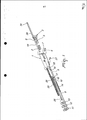
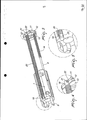
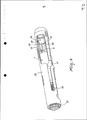
[0020] Outras características e vantagens se tornarão mais aparentes a partir da descrição de modos de realização preferidos, mas não exclusivos da invenção, ilustrados como exemplos não limitativos nos desenhos anexos, nos quais: A fig. 1 é uma vista em perspectiva explodida do conjunto de travamento e de re-engatilhar com trava de culatra pivotante e conjunto de travamento e de re-engatilhar; A fig. 2 é uma vista em perspectiva do conjunto de travamento e de re-engatilhar na condição totalmente montada, na posição de inserção sobre seu assento, dentro da bainha ou extensão do tambor. A fig. 3 é uma vista em perspectiva parcialmente recortada do conjunto de travamento e de re-engatilhar com a mola de recuperação e o correspondente pino-guia montados sobre a trava de culatra pivotante; A fig. 4 é uma vista ampliada, com respeito à figura precedente, mostrando em detalhe a montagem do pino-guia da mola de recuperação sobre a placa de ancoragem do pino; A fig. 5 é uma vista, ampliada em relação à fig. 3, mostrando em detalhe a montagem do pino-guia da mola de recuperação sobre a trava de culatra pivotante; A fig. 6 é uma vista em perspectiva do conjunto de travamento e de re-engatilhar montado sobre a bainha ou extensão do tambor; A fig. 7 é uma vista em perspectiva em seção longitudinal do conjunto de travamento e de re-engatilhar montado sobre a bainha ou extensão do tambor na posição de travamento; A fig. 8 é uma vista em perspectiva parcial mente em seção do conjunto de travamento e de re-engatilhar montado sobre a bainha ou extensão do tambor na posição limite de curso de abertura; A fig. 9 é uma vista em perspectiva em seção longitudinal do conjunto de travamento e de re-engatilhar ilustrando os planos helicoidais inclinados providos sobre a conjunto de travamento e de re-engatilhar e a trava de culatra pivotante; A fig. 10 é uma vista, ampliada com respeito à figura precedente, mostrando em detalhe um recorte longitudinal do conjunto de travamento e de re-engatilhar no qual os planos helicoidais inclinados citados acima estão ressaltados.[0020] Other features and advantages will become more apparent from the description of preferred, but not exclusive, embodiments of the invention, illustrated as non-limiting examples in the accompanying drawings, in which: FIG. 1 is an exploded perspective view of the locking and re-cocking assembly with pivoting yoke lock and locking and re-cocking assembly; Fig. 2 is a perspective view of the locking and re-cocking assembly in the fully assembled condition, in the position of insertion on its seat, inside the sheath or extension of the drum. Fig. 3 is a partially cut-away perspective view of the locking and re-cocking assembly with the recovery spring and the corresponding guide pin mounted on the pivot yoke lock; Fig. 4 is an enlarged view, with respect to the preceding figure, showing in detail the assembly of the guide pin of the recovery spring on the anchor plate of the pin; Fig. 5 is a view, enlarged in relation to fig. 3, showing in detail the assembly of the guide pin of the recovery spring on the pivot yoke lock; Fig. 6 is a perspective view of the locking and re-cocking assembly mounted on the barrel sheath or extension; Fig. 7 is a perspective view in longitudinal section of the locking and re-cocking assembly mounted on the barrel sheath or extension in the locking position; Fig. 8 is a partial perspective view in section of the locking and re-cocking assembly mounted on the barrel sheath or extension in the opening stroke limit position; Fig. 9 is a perspective view in longitudinal section of the locking and re-cocking assembly illustrating the inclined helical planes provided over the locking and re-cocking assembly and the pivoting yoke lock; Fig. 10 is a view, enlarged with respect to the preceding figure, showing in detail a longitudinal section of the locking and re-cocking set in which the inclined helical planes mentioned above are highlighted.
[0021] Com referência às figuras citadas, o conjunto de travamento e de re-engatilhar com trava de culatra pivotante e cabeça de fechamento rotativa de acordo com a presente invenção compreendem uma trava de culatra pivotante q na qual uma mola de recuperação de trava de culatra 2 é inserida e na qual uma cabeça de fechamento rotativa 3 é montada.[0021] With reference to the aforementioned figures, the locking and re-cocking set with pivoting breech lock and rotating closing head according to the present invention comprise a pivoting breech lock q in which a spring lock
[0022] A cabeça de fechamento rotativa 3 é conjuntamente unida à trava de culatra 1 por meio de um pivô de rotação de cabeça 4, que, para concentrar toda a massa móvel necessária para a operação da arma sobre a trava de culatra é conectada conjuntamente à trava de culatra e se encaixa a um carne helicoidal 5 provido sobre um cano cilíndrico 6 da cabeça de travamento.[0022] The rotating
[0023] Esta construção da trava de culatra pivotante 1 minimiza a remoção de material sobre a trava de culatra e permitem desse modo, maximizar sua massa.[0023] This construction of the
[0024] Um corpo ejetor 8 é, então, inserido em um assento 7 que é provido sobre a trava de culatra pivotante 1.[0024] An
[0025] Um pino-guia 9, provido na frente com uma fresagem de orientação 10, é inserido dentro do corpo ejetor 8.[0025] A
[0026] O pino-guia 9 é preso a uma placa de ancoragem de pino-guia da mola 11 e tem, montado em seqüência, um amortecedor 12, de modo a amortecer o impacto da trava de culatra pivotante sobre seu limitador de curso, uma placa de encosto de trava de culatra 13, sobre a qual o curso da trava de culatra pivotante termina durante a abertura, e uma mola ejetora 14.[0026] The
[0027] O corpo ejetor 8, que é substancialmente tubular, tem em sua porção frontal um encosto de frente 15 contra o qual, durante a abertura da trava de culatra, a cápsula colide de modo a ser expelida da arma.[0027] The
[0028] A porção frontal do corpo ejetor 8 tem uma porção em recesso 16 que permite a passagem do cartucho durante elevação e inserção na câmara de disparo.[0028] The front portion of the
[0029] O corpo ejetor 8 tem, sobre sua porção traseira, duas abas 17 e 18, que, quando montadas, definem sua movimentação longitudinal relativa com respeito à trava de culatra pivotante 1 e impedem sua rotação.[0029] The
[0030] A posição do ejetor 8 sobre o conjunto de travamento e de reengatilhar é tal que ele permite que a mola de ejetor 14 opere também como uma mola de recuperação auxiliar, durante a primeira etapa da ação de travamento, e permite que o pino-guia da mola de ejetor 9 guie o cartucho lateralmente em sua etapa de elevar e inserir na câmara de disparo da arma.[0030] The position of the
[0031] Além disso, sobre a trava de culatra pivotante 1, um pino-guia da mola de recuperação 19 é inserido através de um furo e a mola de recuperação_20 é montada na traseira sobre uma ranhura e permite que a trava de culatra pivotante 1 retorne para a posição de travamento.[0031] In addition, over the
[0032] Como mostrado mais claramente nas figs. 3 e 4, o pino-guia da mola de recuperação 19, inserido na trava de culatra pivotante 1, passa através da placa de encosto de trava de culatra 13, sobre a qual a mola de recuperação 20 se apóia.[0032] As shown more clearly in figs. 3 and 4, the guide pin of the
[0033] O pino-guia da mola de recuperação 19 passa através do amortecedor 12 e encaixa, com sua extremidade traseira 21, a placa de ancoragem de pino-guia de mola 11, por meio do recesso 22 da própria placa 11.[0033] The recovery
[0034] Como mostrado mais claramente nas figs. 3 e 5, uma protuberância 23, que o pino-guia da mola de recuperação 19 tem sobre seu lado frontal, constitui, quando o pino está encaixado no recesso 22, um acoplamento frontal da trava de culatra pivotante 1, pela qual todo o conjunto de travamento e de re-engatilhar é completamente montado, como mostrado na fig. 2.[0034] As shown more clearly in figs. 3 and 5, a protuberance 23, which the guide pin of the
[0035] A posição relativa do pino-guia da mola de recuperação 19 é tal que, quando o conjunto está montado,a região plana 24 provida sobre sua porção frontal permite usar o pino tanto como um guia para a cápsula, entes de sua ejeção, como um encosto superior para o cartucho durante elevação e inserção na câmara de disparo.[0035] The relative position of the guide pin of the
[0036] O pino-guia da mola de recuperação 18 também atua como um guia para a cabeça de fechamento rotativa 3 por todo curso de abertura e fechamento da trava de culatra pivotante 1.[0036] The guide pin of the
[0037] Um pino de disparo 25 é montado sobre a trava de culatra pivotante q e, sendo inserido na correspondente mola 26, passa através da cabeça de fechamento rotativa 3, do pivô de rotação de cabeça 4, e da trava de culatra. O pino de disparo 25 é conectado conjuntamente à trava de culatra por meio de um pino de batente 27.[0037] A
[0038] Como mostrado mais claramente na fig. 2, o conjunto de travamento e de re-engatilhar montado é montado no interior da estrutura de suporte da arma, no caso específico da bainha ou extensão do tambor 28, orientando e encaixando a aba 29 do pivô de rotação de cabeça 4 sobre um entalhe 30 que é provido no interior da extensão de barril.[0038] As shown more clearly in fig. 2, the assembled locking and relocking assembly is mounted inside the weapon support structure, in the specific case of the barrel sheath or
[0039] Como mostrado mais claramente na fig. 6, um botão de armar 31 é inserido no conjunto e é montado sobre a trava de culatra pivotante 1 através do entalhe 32 da bainha ou extensão do tambor 28.[0039] As shown more clearly in fig. 6, a
[0040] O entalhe 32 é provido na posição de sobredeslocamento de abertura da trava de culatra, de modo que durante operação normal da arma, ela não pode ser desmontada.[0040] The
[0041] Como mostrado mais claramente na fig6, quando todo o conjunto de travamento e de re-engatilhar está completamente montado sobre a bainha ou extensão do tambor 28, e acoplado à mesma por meio de um anel de fixação 33, tanto o pino-guia da mola de recuperação 19, como o pino-guia da mola de ejetor 9 encaixam, com as respectivas extremidades frontais 34 e 10, em assentos 35 e 36 que são formados sobre a bainha ou extensão do tambor, de modo a constituir duas guia estáveis para o deslizamento das molas 20 e 14 e do corpo de ejetor 8 e de modo a contribuir para a guia da trava de culatra pivotante 1 como uma ajuda à aba 29 do pivô de rotação de cabeça 4 encaixado sobre o correspondente assento 30 da bainha ou extensão do tambor 28 (fig. 2).[0041] As shown more clearly in fig6, when the entire locking and re-cocking assembly is completely mounted on the sheath or extension of the
[0042] Com referência particular à fig. 7, quando a trava de culatra pivotante 1 está na posição travada, e também por uma extensão substancial do curso de abertura, a mola do ejetor 14 não é carregada e o corpo de ejetor 8 é acomodado dentro da trava de culatra,[0042] With particular reference to fig. 7, when the
[0043] Partindo de um dado valor do curso de retração da trava de culatra pivotante 1, a mola do ejetor 14 encontra o corpo do ejetor 8 e começa a ser carregada, empurrando-o para frente até se projetar da cabeça de travamento 3 (fig. 8) e impactar a cápsula, que é expelida da bainha ou extensão do tambor 28.[0043] Starting from a given value of the retracting stroke of the
[0044] Durante todos eu curso, que é definido pela aba 18 que encaixa em um entalhe 37 da trava de culatra pivotante 1 e impede sua rotação (fig. 7), o corpo de ejetor 8 é guiado internamente pelo pino-guia da mola de ejetor 9 e externamente por sua outra aba 17, que atua sobre a bainha ou extensão do tambor 28.[0044] During all I travel, which is defined by
[0045] Durante o curso de abertura, a trava de culatra pivotante 1 comprime tanto a mola de recuperação 20, que é guiada sobre o correspondente pino 19, como a mola de ejetor 14, começando de um certo curso, acumulando, assim, a energia necessária para efetuar o subseqüente ciclo de travamento, como mostrado esquematicamente nas figs. 7 e 8.[0045] During the opening stroke, the
[0046] Com referência particular à fig. 8, uma vez que o curso de abertura tenha terminado, a trava de culatra pivotante 1 impacta mais ou menos violentamente, dependendo da energia do cartucho disparado, seu limite de curso, que está representado pela parede interna do anel de fixação 33, transferindo parte da energia de impacto ao amortecedor 12, que é interposto entre o plano de encosto da trava de culatra 13 e a placa de ancoragem do pino-guia da mola 11.[0046] With particular reference to fig. 8, once the opening stroke has ended, the
[0047] Uma vez que o curso de abertura tenha terminado, a trava de culatra inverte seu movimento e, sob a influência da mola de recuperação 20 e pela mola do ejetor 14, retorna para a posição fechada, elevando o novo cartucho que, sendo guiado lateralmente pelo pino-guia da mola de ejetor 9 e para cima pelo pino-guia da mola de recuperação 19, é inserida na câmara de disparo.[0047] Once the opening stroke has ended, the breech lock reverses its movement and, under the influence of the
[0048] Com referência particular às figs. 9 e 10, na última etapa do curso de travamento da trava de culatra pivotante 1, a rotação da cabeça de fechamento 3 ocorre por meio do contato de um seu plano helicoidal inclinado 38 contra um correspondente plano helicoidal inclinado 39 provido sobre a trava de culatra pivotante 1.[0048] With particular reference to figs. 9 and 10, in the last stage of the locking stroke of the
[0049] O contato provê à trava de culatra de uma velocidade necessária para completar a rotação e travamento da cabeça 3, e também dissipar a maior parte da energia adquirida devido ao empuxo da mola de recuperação 20, assistida pela mola de ejetor 14, no curso de travamento.[0049] The contact provides the breech lock with a speed necessary to complete the rotation and locking of the
[0050] Desse modo, quando o conjunto de travamento e de reengatilhar é aplicado a um sistema de armas atuadas inercialmente, a trava de culatra pivotante 1 chega, com um seu plano 40, a encostar contra a mola de recuo 2, com uma energia que é insuficiente para comprimi-la, evitando, desse modo, as reações elásticas da mola que, de outro modo, geraria um movimento de ricochete e retorno violento da trava de culatra pivotante 1 durante o travamento.[0050] Thus, when the locking and re-cocking set is applied to a system of inertially actuated weapons, the pivoting
[0051] Um conjunto de travamento e de re-engatilhar com trava de culatra pivotante e cabeça de fechamento rotativa, de acordo com a presente invenção, combina simples e compactamente, em um único conjunto e exclusivamente por meio de conexões móveis, todos os componentes necessários para o ciclo de re-engatilhar, travar, abrir, ejetar a cápsula e retornar para travamento necessário à correta operação da arma.[0051] A locking and relocking set with pivoting breech lock and rotating closing head, according to the present invention, combines simply and compactly, in a single set and exclusively by means of mobile connections, all components necessary for the cycle of re-cocking, locking, opening, ejecting the capsule and returning for locking necessary for the correct operation of the weapon.
[0052] A desmontagem, como mostrada esquematicamente na fig. 1, e a montagem, como mostrada na fig. 2, podem ser efetuadas manualmente, sem o uso de ferramentas, provendo os acoplamentos mútuos exclusivamente por meio de conexões móveis.[0052] Disassembly, as shown schematically in fig. 1, and the assembly, as shown in fig. 2, can be performed manually, without the use of tools, providing mutual couplings exclusively through mobile connections.
[0053] Na prática, foi verificado que a invenção atinge a meta e objetivos pretendidos, combinando todas as funções de travamento, abertura, extração e ejeção de cápsula, re-engatilhar e retornar para um travamento em um único conjunto de travamento e de re-engatilhar que é completamente montado dentro da bainha ou extensão do tambor da arma.[0053] In practice, it was found that the invention achieves the intended goal and objectives, combining all the functions of locking, opening, extracting and ejecting the capsule, re-cocking and returning to a lock in a single locking and re-locking set - trigger that is completely assembled inside the barrel or extension of the gun barrel.
[0054] Uma característica importante e vantajosa do conjunto de acordo com a presente invenção é o fato dela concentrar toda a massa necessária à operação inercial do sistema em um único corpo de trava de culatra pivotante.[0054] An important and advantageous feature of the set according to the present invention is the fact that it concentrates all the mass necessary for the inertial operation of the system in a single body of pivoting breech lock.
[0055] Outra vantagem do presente conjunto de travamento e de reengatilhar é o fato do corpo de ejetor, com a correspondente mola e pino-guia da mola, ser montado diretamente sobre a trava de culatra pivotante, de modo que a mola de ejeção contribua, juntamente com a mola de recuperação, também para re-engatilhar a arma durante travamento da trava de culatra e, simultaneamente, o pino-guia da mola atue como guia lateral para o cartucho durante elevação e inserção na câmara de disparo da arma.[0055] Another advantage of the present locking and retracting set is the fact that the ejector body, with the corresponding spring and spring guide pin, is mounted directly on the pivot yoke lock, so that the ejection spring contributes , together with the recovery spring, also to re-cock the weapon when locking the breech lock and, simultaneously, the spring guide pin acts as a lateral guide for the cartridge during lifting and insertion into the firing chamber of the weapon.
[0056] Outra vantagem do presente conjunto de travamento e de reengatilhar é o fato dele ter a mola de recuperação da trava de culatra, e o correspondente pino-guia da mola, montado diretamente sobre a trava de culatra pivotante, de modo a ser capaz de usar o pino-guia da mola de recuperação tanto como um guia da conjunto de travamento e de reengatilhar, durante o ciclo de re-engatilhar, como um encosto superior do cartucho durante elevação e subseqüente guia para sua inserção na câmara de disparo da arma.[0056] Another advantage of the present locking and retracting set is the fact that it has the breech lock recovery spring, and the corresponding spring guide pin, mounted directly on the pivoting breech lock, in order to be able to use the guide pin of the recovery spring both as a guide of the locking and re-cocking assembly, during the re-cocking cycle, as an upper backrest of the cartridge during lifting and subsequent guide for its insertion in the firing chamber of the weapon .
[0057] Outra vantagem do presente conjunto de travamento e de reengatilhar é o fato de, por meio de planos de contraste helicoidais providos sobre a cabeça de travamento rotativa e sobre a trava de culatra pivotante, ele impedir qualquer ricochete da trava de culatra quando, durante travamento, ela se apoiar contra a mola do sistema inercial que é interposta entre a cabeça de travamento rotativa e a trava de culatra pivotante.[0057] Another advantage of the present locking and re-triggering set is the fact that, by means of helical contrast planes provided on the rotating locking head and on the pivoting breech lock, it prevents any rebound of the breech lock when, during locking, it rests against the spring of the inertial system that is interposed between the rotating locking head and the pivoting yoke lock.
[0058] Outra vantagem do presente conjunto de travamento e de reengatilhar é a capacidade de amortecer o impacto da trava de culatra pivotante sobre seu limite de curso de abertura por meio do amortecedor que é conectado diretamente à trava de culatra pivotante.[0058] Another advantage of the present locking and re-triggering set is the ability to cushion the impact of the pivoting breech lock over its opening travel limit by means of the damper that is directly connected to the pivoting breech lock.
[0059] Na prática, o presente conjunto de travamento e de reengatilhar provê um sistema simples e compacto, no qual todos os componentes em movimentação relativa com respeito à arma, a massa inercial, a mola de recuo, a mola de recuperação da trava de culatra, o ejetor e a correspondente mola são contidos dentro da bainha ou extensão do tambor da arma e se movem axialmente com respeito à mesma; isto permite obter simplificações consideráveis pela eliminação de vários componentes, como a ligação e tiras e outros componentes menores necessários para conectar a trava de culatra pivotante à mola de recuperação, que, nos sistemas da técnica anterior, fica, por contraste, localizada dentro da coronha ou haste-guia da arma.[0059] In practice, the present set of locking and rewinding provides a simple and compact system, in which all the components in relative movement with respect to the weapon, the inertial mass, the recoil spring, the recovery spring of the lock yoke, the ejector and the corresponding spring are contained within the sheath or extension of the gun barrel and move axially with respect to it; this allows considerable simplifications to be obtained by eliminating various components, such as the connection and strips and other smaller components necessary to connect the pivot breech lock to the recovery spring, which, in the prior art systems, is, by contrast, located inside the stock. or guide rod on the gun.
[0060] O pedido reivindica a prioridade do pedido de patente italiano MI 2007A001474, depositado em 20 de julho de 2007, cujo teor é aqui incorporado pela referência.[0060] The application claims the priority of the Italian patent application MI 2007A001474, filed on July 20, 2007, the content of which is incorporated by reference.
Claims (6)
Applications Claiming Priority (2)
| Application Number | Priority Date | Filing Date | Title |
|---|---|---|---|
| IT001474A ITMI20071474A1 (en) | 2007-07-20 | 2007-07-20 | CLOSING AND RESET UNIT WITH OSCILLATING SHUTTER AND ROTARY CLOSING HEAD, PARTICULARLY FOR WEAPONS WITH INERTIAL OPERATION USING THE KINETIC ENERGY OF RINCULO |
| ITMI2007A001474 | 2007-07-20 |
Publications (2)
| Publication Number | Publication Date |
|---|---|
| BRPI0803524A2 BRPI0803524A2 (en) | 2009-08-25 |
| BRPI0803524B1 true BRPI0803524B1 (en) | 2020-10-20 |
Family
ID=39865463
Family Applications (1)
| Application Number | Title | Priority Date | Filing Date |
|---|---|---|---|
| BRPI0803524-5A BRPI0803524B1 (en) | 2007-07-20 | 2008-07-21 | locking and re-cocking set, with pivoting breech lock and rotating closing head |
Country Status (10)
| Country | Link |
|---|---|
| US (1) | US7878107B2 (en) |
| EP (1) | EP2017565B1 (en) |
| JP (1) | JP5334479B2 (en) |
| CN (1) | CN101482380B (en) |
| BR (1) | BRPI0803524B1 (en) |
| EA (1) | EA014565B1 (en) |
| ES (1) | ES2698420T3 (en) |
| IL (1) | IL192753A (en) |
| IT (1) | ITMI20071474A1 (en) |
| MX (1) | MX2008009338A (en) |
Families Citing this family (15)
| Publication number | Priority date | Publication date | Assignee | Title |
|---|---|---|---|---|
| US8505227B2 (en) | 2009-03-24 | 2013-08-13 | Sturm, Ruger & Company, Inc. | Firearm with quick coupling barrel interlock system |
| US8479429B2 (en) | 2009-03-24 | 2013-07-09 | Sturm, Ruger & Company, Inc. | Firearm with quick coupling barrel system |
| US9057576B2 (en) | 2009-03-24 | 2015-06-16 | Sturm, Ruger & Company, Inc. | Firearm with quick coupling barrel system |
| US8490312B2 (en) | 2009-03-24 | 2013-07-23 | Sturm, Ruger & Company, Inc. | Quick coupling barrel system for firearm |
| US8356543B2 (en) | 2009-10-02 | 2013-01-22 | Defense Deisigns, LLC | Firearm firing mechanism |
| KR101147975B1 (en) | 2010-04-27 | 2012-05-24 | 태성정밀공업 주식회사 | Rope for carrying something anchor for musical instrument |
| US9488423B2 (en) | 2011-01-14 | 2016-11-08 | Arm West, Llc | Firearm systems and methods |
| AR104686A1 (en) * | 2015-05-22 | 2017-08-09 | Arm West Llc | FIREARM SYSTEMS AND METHODS |
| DE102015008797A1 (en) * | 2015-07-10 | 2017-01-12 | Rheinmetall Waffe Munition Gmbh | Case ejection device |
| US11569605B2 (en) | 2016-12-20 | 2023-01-31 | Te Connectivity Germany Gmbh | Contact device and contact system |
| WO2018117990A1 (en) * | 2016-12-23 | 2018-06-28 | Bahtiyar Tasyagan | Recoil-operated breech mechanism comprising a bolt carrier and rotatable bolt, and providing convenience in assembly-disassembly |
| US10677547B2 (en) | 2018-01-09 | 2020-06-09 | Sturm, Ruger & Company, Inc. | Pump action firearm with slide lock mechanism |
| US11098972B2 (en) * | 2018-03-20 | 2021-08-24 | Taylor. Weapons, Inc. | Recoil system for a self-loading firearm |
| US11549769B1 (en) * | 2019-07-31 | 2023-01-10 | Mark John Roth | Self-locking bolt system not requiring an external surface to lock to |
| CZ308781B6 (en) | 2021-01-08 | 2021-05-12 | Česká Zbrojovka A.S. | Assembly of the closure, the body of the closure and the ejector |
Family Cites Families (20)
| Publication number | Priority date | Publication date | Assignee | Title |
|---|---|---|---|---|
| US2645873A (en) * | 1950-01-31 | 1953-07-21 | Remington Arms Co Inc | Slide-actuated firearm with tilting locking block |
| US3447417A (en) * | 1966-03-09 | 1969-06-03 | Benelli Spa | Gun with a floating breech bolt |
| US3653140A (en) * | 1970-05-04 | 1972-04-04 | Remington Arms Co Inc | Firearm receiver mechanism with a roller detent pin for a telescopic breech-bolt |
| US3967403A (en) * | 1975-01-22 | 1976-07-06 | The United States Of America As Represented By The Secretary Of The Army | Manually-operated firearm with forward-moving barrel and automatic breech lock |
| SE427580B (en) * | 1979-04-11 | 1983-04-18 | Aimpoint Ab | DEVICE WITH ELECTRIC WEAPON WITH PIPE AND END PIECE |
| JPS56500579A (en) * | 1979-04-11 | 1981-04-30 | ||
| US4615132A (en) * | 1983-03-28 | 1986-10-07 | Smith David E | Self loading pistol having a rear sight which secures a detachable breech block insert |
| IT1172795B (en) * | 1983-05-09 | 1987-06-18 | Benelli Armi Spa | CLOSURE WITH ROTARY HEAD AND SHUTTER FOR AUTOMATIC FIREARMS WITH INERTIAL OPERATION USING THE KINETIC ENERGY OF THE RECOIL |
| IT1210375B (en) * | 1987-03-12 | 1989-09-14 | Benelli Armi Spa | TUBULAR TANK CARTRIDGE FEEDING SYSTEM FOR RIFLES WITH SMOOTH BODY AND SEMI-AUTOMATIC MANUAL PUMP OPERATION OR CONVERTIBLE FROM ONE TO THE OTHER TYPE |
| EP0329797A1 (en) * | 1987-12-29 | 1989-08-30 | Renaud Kerbrat | Device for retarding the opening or locking action of a mobile firearm breech block |
| RU2066820C1 (en) * | 1993-06-28 | 1996-09-20 | Государственное предприятие "Ижевский механический завод" | Magazine gun bolt mechanism |
| US5651205A (en) * | 1996-03-29 | 1997-07-29 | Sturm, Ruger & Company, Inc. | Bolt and firing pin locking system for firearm |
| PL185081B1 (en) * | 1997-07-24 | 2003-02-28 | Otkrytoe Aktsionernoe Obschest | Automatic weapon - storming rifle of kalashnikov type |
| US6484430B1 (en) * | 1999-01-27 | 2002-11-26 | Zdf Import/Export, Inc. | Multi-lugged bolt carrier and barrel for rifles |
| US6971202B2 (en) * | 2003-01-27 | 2005-12-06 | Terrence Bender | Gas operated action for auto-loading firearms |
| EP1627199B1 (en) * | 2003-05-23 | 2012-02-08 | Ra Brands, L.L.C. | Bolt assembly with locking system |
| CA2535659C (en) * | 2003-08-11 | 2011-01-18 | Fats, Inc. | Locking assembly for firearm simulators |
| US7971379B2 (en) * | 2004-02-13 | 2011-07-05 | Rmdi, Llc | Firearm |
| ITMI20041893A1 (en) * | 2004-10-06 | 2005-01-06 | Beretta Armi Spa | FIREARMS WITH SELECTOR DEVICE FOR THE RIGHT OR LEFT EXPULSION OF A BOSSOLO |
| BE1016821A3 (en) * | 2005-10-25 | 2007-07-03 | Browning Int Sa | IMPROVED SEMI-AUTOMATIC RIFLE |
-
2007
- 2007-07-20 IT IT001474A patent/ITMI20071474A1/en unknown
-
2008
- 2008-07-08 EP EP08012289.8A patent/EP2017565B1/en active Active
- 2008-07-08 ES ES08012289T patent/ES2698420T3/en active Active
- 2008-07-08 US US12/217,765 patent/US7878107B2/en active Active
- 2008-07-10 IL IL192753A patent/IL192753A/en active IP Right Grant
- 2008-07-18 CN CN2008101756631A patent/CN101482380B/en active Active
- 2008-07-18 JP JP2008187632A patent/JP5334479B2/en active Active
- 2008-07-18 EA EA200801578A patent/EA014565B1/en unknown
- 2008-07-18 MX MX2008009338A patent/MX2008009338A/en active IP Right Grant
- 2008-07-21 BR BRPI0803524-5A patent/BRPI0803524B1/en active IP Right Grant
Also Published As
| Publication number | Publication date |
|---|---|
| IL192753A0 (en) | 2009-08-03 |
| US7878107B2 (en) | 2011-02-01 |
| EP2017565A2 (en) | 2009-01-21 |
| CN101482380A (en) | 2009-07-15 |
| JP2009041902A (en) | 2009-02-26 |
| EP2017565A3 (en) | 2015-04-08 |
| BRPI0803524A2 (en) | 2009-08-25 |
| MX2008009338A (en) | 2009-03-05 |
| US20090019754A1 (en) | 2009-01-22 |
| CN101482380B (en) | 2013-09-25 |
| IL192753A (en) | 2012-03-29 |
| EP2017565B1 (en) | 2018-08-29 |
| EA200801578A1 (en) | 2009-02-27 |
| ES2698420T3 (en) | 2019-02-04 |
| EA014565B1 (en) | 2010-12-30 |
| JP5334479B2 (en) | 2013-11-06 |
| ITMI20071474A1 (en) | 2009-01-21 |
Similar Documents
| Publication | Publication Date | Title |
|---|---|---|
| BRPI0803524B1 (en) | locking and re-cocking set, with pivoting breech lock and rotating closing head | |
| ES2404162T3 (en) | Firearm device | |
| US8578836B2 (en) | Firearm with enhanced handling by dissipating the effects of recoil and muzzle climb | |
| BRPI0803529B1 (en) | modular handgun | |
| HUE026754T2 (en) | Handgun with a locking device | |
| WO1997042460A1 (en) | Automatic firearm arranged for high safety and rapid dismantling | |
| US10281225B2 (en) | Self-loading pistol with selective slide lock delaying the opening movement during firing but facilitating manual cocking | |
| CN105571388B (en) | A kind of spiral revolution rigid locking mechanism of pistol | |
| US4467698A (en) | Angular shape firing pin for use with a collapsible toggle recoil in a hand held weapon | |
| EP0093089B1 (en) | Reconversion device from a semi-automatic operation system to a pump system and vice versa for fixed barrel sporting and defense guns | |
| BR112020004260A2 (en) | machine gun | |
| ES2961980T3 (en) | Pellet loading system | |
| US2705847A (en) | Pistol, including improved operating mechanism | |
| ES2321929T3 (en) | SMALL FIREARM WITH LOCKED LOCK. | |
| ES2304866B1 (en) | DOUBLE SHOT MECHANISM FOR COUPLING IN AUTOMATIC WEAPONS. | |
| US2590897A (en) | Shoulder mortar | |
| US8020331B2 (en) | Linear bolt mechanism for a gun | |
| US97821A (en) | Fire-arms | |
| CN110220410A (en) | A kind of hybrid blocking mechanism | |
| CN112179201B (en) | Be applied to unmanned aerial vehicle's no recoil firearm | |
| TWI703303B (en) | Cycling shooting mechanism of simple blowback weapon | |
| CN217058513U (en) | Columnar soft bullet feeding mechanism and toy gun | |
| US818739A (en) | Firearm. | |
| ES2257709T3 (en) | GUN POWERED GUN. | |
| KR20150086945A (en) | Cylinder-type gas exhauster and shock absorber of gun |
Legal Events
| Date | Code | Title | Description |
|---|---|---|---|
| B06G | Technical and formal requirements: other requirements [chapter 6.7 patent gazette] |
Free format text: SOLICITA-SE A REGULARIZACAO DA PROCURACAO, UMA VEZ QUE BASEADO NO ARTIGO 216 1O DA LPI, O DOCUMENTO DE PROCURACAO DEVE SER APRESENTADO EM SUA FORMA AUTENTICADA; OU SEGUNDO PARECER DA PROCURADORIA NO 074/93, DEVE CONSTAR UMA DECLARACAO DE VERACIDADE, A QUAL DEVE SER ASSINADA POR UMA PESSOA DEVIDAMENTE AUTORIZADA A REPRESENTAR O INTERESSADO, DEVENDO A MESMA CONSTAR NO INSTRUMENTO DE PROCURACAO, OU NO SEU SUBSTABELECIMENTO. |
|
| B03A | Publication of a patent application or of a certificate of addition of invention [chapter 3.1 patent gazette] | ||
| B06F | Objections, documents and/or translations needed after an examination request according [chapter 6.6 patent gazette] | ||
| B06U | Preliminary requirement: requests with searches performed by other patent offices: procedure suspended [chapter 6.21 patent gazette] | ||
| B09A | Decision: intention to grant [chapter 9.1 patent gazette] | ||
| B16A | Patent or certificate of addition of invention granted [chapter 16.1 patent gazette] |
Free format text: PRAZO DE VALIDADE: 10 (DEZ) ANOS CONTADOS A PARTIR DE 20/10/2020, OBSERVADAS AS CONDICOES LEGAIS. |