EP2017529A1 - Brenner - Google Patents
Brenner Download PDFInfo
- Publication number
- EP2017529A1 EP2017529A1 EP20080160478 EP08160478A EP2017529A1 EP 2017529 A1 EP2017529 A1 EP 2017529A1 EP 20080160478 EP20080160478 EP 20080160478 EP 08160478 A EP08160478 A EP 08160478A EP 2017529 A1 EP2017529 A1 EP 2017529A1
- Authority
- EP
- European Patent Office
- Prior art keywords
- burner
- tube
- tubes
- flange
- grooves
- Prior art date
- Legal status (The legal status is an assumption and is not a legal conclusion. Google has not performed a legal analysis and makes no representation as to the accuracy of the status listed.)
- Granted
Links
Images

Classifications
-
- F—MECHANICAL ENGINEERING; LIGHTING; HEATING; WEAPONS; BLASTING
- F23—COMBUSTION APPARATUS; COMBUSTION PROCESSES
- F23C—METHODS OR APPARATUS FOR COMBUSTION USING FLUID FUEL OR SOLID FUEL SUSPENDED IN A CARRIER GAS OR AIR
- F23C7/00—Combustion apparatus characterised by arrangements for air supply
- F23C7/008—Flow control devices
-
- F—MECHANICAL ENGINEERING; LIGHTING; HEATING; WEAPONS; BLASTING
- F23—COMBUSTION APPARATUS; COMBUSTION PROCESSES
- F23D—BURNERS
- F23D17/00—Burners for combustion simultaneously or alternately of gaseous or liquid or pulverulent fuel
- F23D17/002—Burners for combustion simultaneously or alternately of gaseous or liquid or pulverulent fuel gaseous or liquid fuel
-
- F—MECHANICAL ENGINEERING; LIGHTING; HEATING; WEAPONS; BLASTING
- F23—COMBUSTION APPARATUS; COMBUSTION PROCESSES
- F23D—BURNERS
- F23D2900/00—Special features of, or arrangements for burners using fluid fuels or solid fuels suspended in a carrier gas
- F23D2900/11402—Airflow diaphragms at burner nozzle
Definitions
- the present invention relates to a burner, in particular a burner for a cement plant.
- An axially extending type burner comprising an axial flow primary air supply annulus which surrounds all of the fuel supply lines and which is delimited by an inner tube extending along the axis of the burner and a co-axial outer tube to the inner tube, the two tubes being axially movable relative to each other in translation in the axial direction between an open position and a closed position .
- Such a burner is for example disclosed in the patent application EP 967 434 , is usually used for cement plants, and includes two primary air supply lines surrounding all fuel supply lines of the burner. These two lines are the axial flow air supply line at the outlet of which the flow of air is parallel to the burner axis, possibly with a slight radial component, and a flow air supply line. tangential output of which the flow of air has a tangential component so as to form a swirling flow around the axis of the burner. In addition, such a burner is generally surrounded by secondary air supply lines.
- a first of the two tubes delimiting the axial flow primary air supply line carries, close to its downstream end, an annular flange which comprises grooves extending substantially along the axial direction of the tube, the second tube comprising a closing portion arranged so that, when the two tubes are in the open position, the distance radially separating the closing portion of the flange allows a significant passage of air between these two bodies, and when the two tubes are in the closed position, this distance is substantially zero so that almost all (or all) of the air passes through the grooves.
- the outlet air coming both from the grooves formed in the flange and the annular space between the flange and the second tube, is distributed continuously over the entire periphery of the pipe, and thus surrounds the flame and thus protects the beginning of the latter from the rapid introduction of secondary air, which in particular reduces the rate of nitrogen oxides.
- the outlet air coming solely from the grooves formed in the flange, is distributed discontinuously over the entire periphery of the pipe, and the air jets (corresponding to each groove) attract the 'air secondary (usually having a high temperature) from the origin of the flame, which activates the latter and allows to activate the cooking of the material in the oven.
- the figure 1 illustrates a portion of a burner 1 which extends along an axis 2 and which conventionally comprises solid fuel supply lines and / or liquid and / or gas and a central duct air intake which is used to allow the attachment of the flame to a flame stabilizer and to cool the latter.
- the burner 1 also comprises a tangential flow primary air supply peripheral duct 3 which surrounds the central air supply duct and, in the present example, all of the fuel supply ducts.
- This tangential flow primary air supply peripheral duct 3 comprises devices making it possible to impart a tangential component to the flow of air at its outlet.
- the tangential flow air supply line 3 is in accordance with one or the other of the conduits disclosed in the two patent applications. FR 2,887,597 and FR 06 04 829 .
- the burner 1 further comprises a peripheral axial flow primary supply pipe 4 at the outlet of which the air has a substantially axial flow, that is to say without tangential component (or at least whose component tangential is weak, less than 10 ° with respect to the axis 2 of the burner 1).
- the airflow is axial.
- This axial flow primary air supply peripheral pipe 4 surrounds all the fuel supply pipes and the central air supply pipe.
- the axial flow air supply pipe 4 surrounds the tangential flow air supply pipe 3.
- the axial flow air supply line 4 is delimited by two tubes 5, 6 movable relative to one another in translation along the axis 2 of the burner 1, an inner tube 5 which, in the present embodiments, defines the axial flow air supply line 4 of the supply line tangential flow air 3, and an outer tube 6 which is coaxial with the inner tube 5 and forms the tube defining the burner 1 of the secondary air supply lines.
- the two tubes 5, 6 are axially movable between an open position and a closed position.
- one of the two tubes (in this case, the inner tube 5) carries, near its downstream end 7 (here, at its downstream end 7), an annular flange 8 (stationary relative to the inner tube 5) .
- This annular flange 8 has grooves 9 which are regularly distributed angularly, which pass through it from one side, and which extend parallel to the axis 2 of the burner 1. In this case, the grooves represent about one third of the periphery of the flange 8.
- each groove 9 is delimited on the one hand by a bottom wall 10 which, in this case, does not have any inclination in the direction of a displacement along the axis 2 of the burner 1, and, secondly, by two side walls 11 which, in this case, are parallel to each other and to the direction of the axis 2 of the burner 1, and are normal to the bottom wall 10.
- the grooves 9 made in the annular flange 8 are open radially over their entire length, the flange 8 not carrying an upper wall facing the bottom wall 10.
- the annular flange 8 has an upstream end 12 which has a radial inclination in the direction of a coming towards the outer tube 6 for a displacement along the axis 2 of the burner 1 upstream downstream.
- the upstream end of the flange is conical (to the upstream orifices of the grooves 9) with a cone center disposed upstream of the tube.
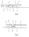
- the other tube (in this case, the outer tube 6) comprises a closing portion 13, 15 (stationary with respect to the outer tube 6) which is arranged so that, when the two tubes 5, 6 are in position d opening, the distance separating the closing portion 13, 15 of the flange 8 allows a significant passage of air between the flange 8 and the second tube 6 in order to have an axial air flow at the outlet of the pipe 4 angularly continuous (cf. figures 1 and 4 ), and when the two tubes 5, 6 are in the closed position, the distance separating the closing portion 13, 15 of the flange 8 is substantially zero in order to have an air flow at the outlet of the pipe 4 angularly discontinuous and limited to the angular sectors corresponding to the grooves 9 (cf. figures 2 and 5 ).
- the closing portion 13 is a surface having a radial inclination in the direction of a spacing of the inner tube 5 for a displacement along the axis 2 of the burner 1 upstream downstream.
- the closing portion 13 is conical with a cone center disposed upstream of the tube.
- the half-angle at the top of the cone is about 10 °.
- the downstream end 14 of the closing portion 13 is the downstream end 14 of the outer tube 6.
- the two tubes 5, 6 are in an open position in which an annular space exists (and is relatively large) between the flange 8 and the outer tube 6.
- the two tubes 5, 6 are in a closed position where the closing portion 13 is substantially in abutment against the annular flange 8 (against the upstream end 12 of the flange 8), thus limiting the passage section of the air in the grooves only 9.
- the flange 8 is in a position which is upstream of the position it takes when the tube which carries it is in the open position.
- the closing portion 15 comprises a first surface 16 having a radial inclination in the direction of an approximation of the inner tube 5 for a displacement along the axis 2 of the burner 1 from upstream to the downstream.
- the first surface 16 is conical with a cone center disposed downstream of the tube.
- the half-angle at the top of the cone is about 10 °.
- the closing portion 15 comprises a second surface 17 (cylindrical) extending in the downstream direction, the first surface 16.
- the second surface 17 has a diameter equal to the outer diameter of the flange 8 (the clearance necessary for the sliding of two tubes close).
- the two tubes 5, 6 are in an open position in which an annular space exists between the flange 8 and the outer tube 6.
- the two tubes 5, 6 are in a closed position where the cylindrical surface 17 covers the annular flange 8, thus limiting the air passage section to the grooves 9 only.
- the flange is carried by the outer tube and the closing portion by the inner tube.
- the annular flange prefferably has a different shape, especially at its upstream end, and / or to have upper walls facing the bottom walls and delimiting, with these and the side walls, the grooves. It would also be possible for the bottom walls to have a slight radial inclination (less than 10 °) in order to impart a radial component to the air flow at their outlet, and / or that the lateral walls have a tangential component in order to confer a component tangential to the flow of air at their output.
- the closure portion could be a surface having a radial inclination in the direction of a spacing of the inner tube for a displacement along the axis of the burner from downstream to upstream (for example, the portion of closure could be tapered with a cone center disposed downstream of the tube, with an apex half-angle of about 10 °).
- the two tubes define between them an important annular space at the flange, and in the closed position (position in which the flange is downstream of the position it takes when the tube that carries it is in opening position), the closing portion would be substantially in abutment against the annular flange (against the downstream end of the flange), thus limiting the section of passage of the air to the grooves only.
Landscapes
- Engineering & Computer Science (AREA)
- Chemical & Material Sciences (AREA)
- Combustion & Propulsion (AREA)
- Mechanical Engineering (AREA)
- General Engineering & Computer Science (AREA)
- Gas Burners (AREA)
Applications Claiming Priority (1)
| Application Number | Priority Date | Filing Date | Title |
|---|---|---|---|
| FR0705305A FR2919043A1 (fr) | 2007-07-20 | 2007-07-20 | Bruleur comportant une conduite annulaire d'alimentation en air |
Publications (2)
| Publication Number | Publication Date |
|---|---|
| EP2017529A1 true EP2017529A1 (de) | 2009-01-21 |
| EP2017529B1 EP2017529B1 (de) | 2015-11-18 |
Family
ID=39111354
Family Applications (1)
| Application Number | Title | Priority Date | Filing Date |
|---|---|---|---|
| EP08160478.7A Not-in-force EP2017529B1 (de) | 2007-07-20 | 2008-07-16 | Brenner |
Country Status (3)
| Country | Link |
|---|---|
| EP (1) | EP2017529B1 (de) |
| CN (1) | CN101349426A (de) |
| FR (1) | FR2919043A1 (de) |
Families Citing this family (2)
| Publication number | Priority date | Publication date | Assignee | Title |
|---|---|---|---|---|
| FR3024765B1 (fr) * | 2014-08-06 | 2016-07-29 | Fives Pillard | Bruleur a injection d'air ou de gaz ajustable |
| CN108730970A (zh) * | 2017-04-15 | 2018-11-02 | 南京建安机械制造有限公司 | 五通道煤粉燃烧器 |
Citations (8)
| Publication number | Priority date | Publication date | Assignee | Title |
|---|---|---|---|---|
| GB1260443A (en) * | 1970-02-10 | 1972-01-19 | Todd Comb Ltd | A fuel burner assembly |
| US4199934A (en) * | 1975-07-24 | 1980-04-29 | Daimler-Benz Aktiengesellschaft | Combustion chamber, especially for gas turbines |
| EP0421903A2 (de) * | 1989-10-04 | 1991-04-10 | ENTREPRISE GENERALE DE CHAUFFAGE INDUSTRIEL PILLARD. Société anonyme dite: | Verfahren zum Betreiben eines Brenners und Brenner für Drehofen |
| US5235813A (en) * | 1990-12-24 | 1993-08-17 | United Technologies Corporation | Mechanism for controlling the rate of mixing in combusting flows |
| EP0967434A1 (de) | 1998-06-24 | 1999-12-29 | Entreprise Generale De Chauffage Industriel Pillard | Brenner mit konzentrischer Luftzufuhr und zentral angeordnetem Stabilisator |
| WO2003081132A2 (en) * | 2002-03-16 | 2003-10-02 | Exxonmobil Chemical Patents Inc. | Improved burner with low nox emissions |
| FR2887597A1 (fr) | 2005-06-27 | 2006-12-29 | Egci Pillard Sa | Conduite annulaire et bruleur comportant une telle conduite |
| EP1862735A2 (de) * | 2006-05-30 | 2007-12-05 | Entreprise Générale de Chauffage Industriel Pillard | Zweistrom-Ringleitung und Brenner, der eine solche Leitung umfasst |
-
2007
- 2007-07-20 FR FR0705305A patent/FR2919043A1/fr not_active Withdrawn
-
2008
- 2008-07-16 EP EP08160478.7A patent/EP2017529B1/de not_active Not-in-force
- 2008-07-21 CN CNA2008101307863A patent/CN101349426A/zh active Pending
Patent Citations (9)
| Publication number | Priority date | Publication date | Assignee | Title |
|---|---|---|---|---|
| GB1260443A (en) * | 1970-02-10 | 1972-01-19 | Todd Comb Ltd | A fuel burner assembly |
| US4199934A (en) * | 1975-07-24 | 1980-04-29 | Daimler-Benz Aktiengesellschaft | Combustion chamber, especially for gas turbines |
| EP0421903A2 (de) * | 1989-10-04 | 1991-04-10 | ENTREPRISE GENERALE DE CHAUFFAGE INDUSTRIEL PILLARD. Société anonyme dite: | Verfahren zum Betreiben eines Brenners und Brenner für Drehofen |
| US5235813A (en) * | 1990-12-24 | 1993-08-17 | United Technologies Corporation | Mechanism for controlling the rate of mixing in combusting flows |
| EP0967434A1 (de) | 1998-06-24 | 1999-12-29 | Entreprise Generale De Chauffage Industriel Pillard | Brenner mit konzentrischer Luftzufuhr und zentral angeordnetem Stabilisator |
| WO2003081132A2 (en) * | 2002-03-16 | 2003-10-02 | Exxonmobil Chemical Patents Inc. | Improved burner with low nox emissions |
| FR2887597A1 (fr) | 2005-06-27 | 2006-12-29 | Egci Pillard Sa | Conduite annulaire et bruleur comportant une telle conduite |
| EP1862735A2 (de) * | 2006-05-30 | 2007-12-05 | Entreprise Générale de Chauffage Industriel Pillard | Zweistrom-Ringleitung und Brenner, der eine solche Leitung umfasst |
| FR2901852A1 (fr) | 2006-05-30 | 2007-12-07 | Egci Pillard Sa | Conduite annulaire a double flux et bruleur comportant une telle conduite |
Also Published As
| Publication number | Publication date |
|---|---|
| CN101349426A (zh) | 2009-01-21 |
| EP2017529B1 (de) | 2015-11-18 |
| FR2919043A1 (fr) | 2009-01-23 |
Similar Documents
| Publication | Publication Date | Title |
|---|---|---|
| CA2780594C (fr) | Chambre de combustion avec bougie d'allumage ventilee | |
| EP2815183B1 (de) | Luft- und brennstoffeinspritzungsvorrichtung für eine turbomaschinenbrennkammer | |
| CA2636659A1 (fr) | Deflecteur de fond de chambre, chambre de combustion le comportant et moteur a turbine a gaz en etant equipe | |
| WO2005124495A1 (fr) | Cartouche thermostatique de regulation de fluides chaud et froid a melanger, ainsi que robinet mitigeur muni d'une telle cartouche | |
| EP3569929A1 (de) | Einheit für eine brennkammer eines turbotriebwerks | |
| EP2017529B1 (de) | Brenner | |
| EP0703410A1 (de) | Brennerstein für Sauerstoff-Brennstoff-Brenner, Brenner mit einem solchen Brennerstein und Verfahren zur Verwendung | |
| FR2921462A1 (fr) | Chambre de combustion annulaire de moteur a turbine a gaz | |
| EP0967434B1 (de) | Brenner mit konzentrischer Luftzufuhr und zentral angeordnetem Stabilisator | |
| EP1862735B1 (de) | Zweistrom-Ringleitung und Brenner, der eine solche Leitung umfasst | |
| EP2283278B1 (de) | Brenner mit peripheren injektionspunkten für axialen luftfluss | |
| FR2887597A1 (fr) | Conduite annulaire et bruleur comportant une telle conduite | |
| EP3443131B1 (de) | Blaslanzendüse | |
| EP1980788B1 (de) | Brenner für gasförmigen Kraftstoff | |
| FR2901313A1 (fr) | Dispositif de degazage pour une turbomachine | |
| EP3903029B1 (de) | Brenner mit einstellbarer flamme | |
| EP2166285A1 (de) | Mixer for boiler | |
| BE1023582B1 (fr) | Nez de lance de soufflage | |
| FR2998946A1 (fr) | Bruleur charbon a double flux | |
| FR3091726A1 (fr) | Dispositif de purification de gaz d’échappement comprenant une cartouche amovible, et ligne d’échappement comprenant un tel dispositif | |
| FR2695712A1 (fr) | Tube de flamme pour brûleur à combustibles liquides ou gazeux. | |
| FR2763387A1 (fr) | Dispositif d'injection de gaz pour l'aide au tirage dans un systeme de transport de fluide gazeux | |
| FR2888899A1 (fr) | Ensemble de conduites annulaires et bruleur comprenant un tel ensemble |
Legal Events
| Date | Code | Title | Description |
|---|---|---|---|
| PUAI | Public reference made under article 153(3) epc to a published international application that has entered the european phase |
Free format text: ORIGINAL CODE: 0009012 |
|
| AK | Designated contracting states |
Kind code of ref document: A1 Designated state(s): AT BE BG CH CY CZ DE DK EE ES FI FR GB GR HR HU IE IS IT LI LT LU LV MC MT NL NO PL PT RO SE SI SK TR |
|
| AX | Request for extension of the european patent |
Extension state: AL BA MK RS |
|
| 17P | Request for examination filed |
Effective date: 20090518 |
|
| AKX | Designation fees paid |
Designated state(s): AT DE DK ES FR |
|
| GRAP | Despatch of communication of intention to grant a patent |
Free format text: ORIGINAL CODE: EPIDOSNIGR1 |
|
| INTG | Intention to grant announced |
Effective date: 20150707 |
|
| GRAS | Grant fee paid |
Free format text: ORIGINAL CODE: EPIDOSNIGR3 |
|
| GRAA | (expected) grant |
Free format text: ORIGINAL CODE: 0009210 |
|
| AK | Designated contracting states |
Kind code of ref document: B1 Designated state(s): AT DE DK ES FR |
|
| REG | Reference to a national code |
Ref country code: AT Ref legal event code: REF Ref document number: 761764 Country of ref document: AT Kind code of ref document: T Effective date: 20151215 |
|
| REG | Reference to a national code |
Ref country code: DE Ref legal event code: R096 Ref document number: 602008041226 Country of ref document: DE |
|
| PG25 | Lapsed in a contracting state [announced via postgrant information from national office to epo] |
Ref country code: ES Free format text: LAPSE BECAUSE OF FAILURE TO SUBMIT A TRANSLATION OF THE DESCRIPTION OR TO PAY THE FEE WITHIN THE PRESCRIBED TIME-LIMIT Effective date: 20151118 |
|
| REG | Reference to a national code |
Ref country code: FR Ref legal event code: PLFP Year of fee payment: 9 |
|
| REG | Reference to a national code |
Ref country code: DE Ref legal event code: R097 Ref document number: 602008041226 Country of ref document: DE |
|
| PG25 | Lapsed in a contracting state [announced via postgrant information from national office to epo] |
Ref country code: DK Free format text: LAPSE BECAUSE OF FAILURE TO SUBMIT A TRANSLATION OF THE DESCRIPTION OR TO PAY THE FEE WITHIN THE PRESCRIBED TIME-LIMIT Effective date: 20151118 |
|
| PLBE | No opposition filed within time limit |
Free format text: ORIGINAL CODE: 0009261 |
|
| STAA | Information on the status of an ep patent application or granted ep patent |
Free format text: STATUS: NO OPPOSITION FILED WITHIN TIME LIMIT |
|
| 26N | No opposition filed |
Effective date: 20160819 |
|
| REG | Reference to a national code |
Ref country code: FR Ref legal event code: PLFP Year of fee payment: 10 |
|
| REG | Reference to a national code |
Ref country code: AT Ref legal event code: UEP Ref document number: 761764 Country of ref document: AT Kind code of ref document: T Effective date: 20151118 |
|
| REG | Reference to a national code |
Ref country code: FR Ref legal event code: PLFP Year of fee payment: 11 |
|
| PGFP | Annual fee paid to national office [announced via postgrant information from national office to epo] |
Ref country code: DE Payment date: 20220621 Year of fee payment: 15 Ref country code: AT Payment date: 20220623 Year of fee payment: 15 |
|
| PGFP | Annual fee paid to national office [announced via postgrant information from national office to epo] |
Ref country code: FR Payment date: 20230621 Year of fee payment: 16 |
|
| REG | Reference to a national code |
Ref country code: DE Ref legal event code: R119 Ref document number: 602008041226 Country of ref document: DE |
|
| REG | Reference to a national code |
Ref country code: AT Ref legal event code: MM01 Ref document number: 761764 Country of ref document: AT Kind code of ref document: T Effective date: 20230716 |
|
| PG25 | Lapsed in a contracting state [announced via postgrant information from national office to epo] |
Ref country code: AT Free format text: LAPSE BECAUSE OF NON-PAYMENT OF DUE FEES Effective date: 20230716 |
|
| PG25 | Lapsed in a contracting state [announced via postgrant information from national office to epo] |
Ref country code: DE Free format text: LAPSE BECAUSE OF NON-PAYMENT OF DUE FEES Effective date: 20240201 Ref country code: AT Free format text: LAPSE BECAUSE OF NON-PAYMENT OF DUE FEES Effective date: 20230716 |
|
| PG25 | Lapsed in a contracting state [announced via postgrant information from national office to epo] |
Ref country code: FR Free format text: LAPSE BECAUSE OF NON-PAYMENT OF DUE FEES Effective date: 20240731 |