EP2017508B1 - Sealing arrangement and method for sealing off an interval as well as component assembly for holding a seal - Google Patents
Sealing arrangement and method for sealing off an interval as well as component assembly for holding a seal Download PDFInfo
- Publication number
- EP2017508B1 EP2017508B1 EP20080012345 EP08012345A EP2017508B1 EP 2017508 B1 EP2017508 B1 EP 2017508B1 EP 20080012345 EP20080012345 EP 20080012345 EP 08012345 A EP08012345 A EP 08012345A EP 2017508 B1 EP2017508 B1 EP 2017508B1
- Authority
- EP
- European Patent Office
- Prior art keywords
- seal
- sealing
- section
- groove
- seal body
- Prior art date
- Legal status (The legal status is an assumption and is not a legal conclusion. Google has not performed a legal analysis and makes no representation as to the accuracy of the status listed.)
- Active
Links
- 238000007789 sealing Methods 0.000 title claims description 145
- 238000000034 method Methods 0.000 title claims description 15
- 230000000694 effects Effects 0.000 claims description 12
- 239000000463 material Substances 0.000 claims description 9
- 239000011324 bead Substances 0.000 description 3
- 230000003993 interaction Effects 0.000 description 3
- 238000000926 separation method Methods 0.000 description 3
- 238000013461 design Methods 0.000 description 2
- 230000000712 assembly Effects 0.000 description 1
- 238000000429 assembly Methods 0.000 description 1
- 230000006835 compression Effects 0.000 description 1
- 238000007906 compression Methods 0.000 description 1
- 230000001419 dependent effect Effects 0.000 description 1
- 238000011161 development Methods 0.000 description 1
- 238000006073 displacement reaction Methods 0.000 description 1
- 230000006872 improvement Effects 0.000 description 1
- 238000003780 insertion Methods 0.000 description 1
- 230000037431 insertion Effects 0.000 description 1
- 238000004519 manufacturing process Methods 0.000 description 1
- 238000012986 modification Methods 0.000 description 1
- 230000004048 modification Effects 0.000 description 1
- 230000008569 process Effects 0.000 description 1
- 230000009467 reduction Effects 0.000 description 1
- 230000003014 reinforcing effect Effects 0.000 description 1
- 239000003566 sealing material Substances 0.000 description 1
- 230000008719 thickening Effects 0.000 description 1
Images

Classifications
-
- F—MECHANICAL ENGINEERING; LIGHTING; HEATING; WEAPONS; BLASTING
- F16—ENGINEERING ELEMENTS AND UNITS; GENERAL MEASURES FOR PRODUCING AND MAINTAINING EFFECTIVE FUNCTIONING OF MACHINES OR INSTALLATIONS; THERMAL INSULATION IN GENERAL
- F16J—PISTONS; CYLINDERS; SEALINGS
- F16J15/00—Sealings
- F16J15/02—Sealings between relatively-stationary surfaces
- F16J15/06—Sealings between relatively-stationary surfaces with solid packing compressed between sealing surfaces
- F16J15/062—Sealings between relatively-stationary surfaces with solid packing compressed between sealing surfaces characterised by the geometry of the seat
-
- F—MECHANICAL ENGINEERING; LIGHTING; HEATING; WEAPONS; BLASTING
- F16—ENGINEERING ELEMENTS AND UNITS; GENERAL MEASURES FOR PRODUCING AND MAINTAINING EFFECTIVE FUNCTIONING OF MACHINES OR INSTALLATIONS; THERMAL INSULATION IN GENERAL
- F16J—PISTONS; CYLINDERS; SEALINGS
- F16J15/00—Sealings
- F16J15/02—Sealings between relatively-stationary surfaces
- F16J15/021—Sealings between relatively-stationary surfaces with elastic packing
- F16J15/022—Sealings between relatively-stationary surfaces with elastic packing characterised by structure or material
- F16J15/024—Sealings between relatively-stationary surfaces with elastic packing characterised by structure or material the packing being locally weakened in order to increase elasticity
- F16J15/025—Sealings between relatively-stationary surfaces with elastic packing characterised by structure or material the packing being locally weakened in order to increase elasticity and with at least one flexible lip
-
- F—MECHANICAL ENGINEERING; LIGHTING; HEATING; WEAPONS; BLASTING
- F16—ENGINEERING ELEMENTS AND UNITS; GENERAL MEASURES FOR PRODUCING AND MAINTAINING EFFECTIVE FUNCTIONING OF MACHINES OR INSTALLATIONS; THERMAL INSULATION IN GENERAL
- F16J—PISTONS; CYLINDERS; SEALINGS
- F16J15/00—Sealings
- F16J15/02—Sealings between relatively-stationary surfaces
- F16J15/06—Sealings between relatively-stationary surfaces with solid packing compressed between sealing surfaces
- F16J15/10—Sealings between relatively-stationary surfaces with solid packing compressed between sealing surfaces with non-metallic packing
- F16J15/104—Sealings between relatively-stationary surfaces with solid packing compressed between sealing surfaces with non-metallic packing characterised by structure
- F16J15/106—Sealings between relatively-stationary surfaces with solid packing compressed between sealing surfaces with non-metallic packing characterised by structure homogeneous
Definitions
- the invention relates to a sealing arrangement comprising a component having a recess and a seal having a sealing body, which comprises at least one sealing section, wherein the sealing body further comprises two guide sections in an upper region and two other guide sections in a lower region, wherein the four guide sections of distinguish the sealing portion and the seal body is guided by the four guide portions in a loaded and / or unloaded state in the recess.
- the invention relates to a method for sealing a gap by means of a seal, which is formed by at least two components, wherein the seal comprises a sealing body, which is placed for sealing the gap in the gap and which comprises at least one sealing portion, over the the space is sealed, wherein the sealing body further comprises two guide portions in an upper portion and two other guide portions in a lower portion, wherein the four guide portions are different from the sealing portion, and the seal body is guided by the four guide portions in a loaded and / or unloaded state in the gap.
- the invention relates to a component assembly and a use of the seal assembly or the component group.
- the DE 103 49 921 A1 describes a seal having a sealing body which is placeable in a groove for sealing a gap formed between a end cover and a housing and which includes a slightly curved surface of the base and sealing beads over which the gap is sealed.
- the EP 0 488 879 A1 describes a seal having a sealing body which is placeable into a groove for sealing a gap formed between a cover and a cylinder block and which includes an axial rib and a bead over which the gap is sealed.
- the sealing body comprises two lateral flanks, with which the sealing body is guided in the groove.
- the DE 198 48 563 A1 describes a gasket having a pair of rib-like, laterally protruding parts in an upper region and two other rib-like, laterally protruding parts in a lower region.
- the projecting parts are pressed against an inner surface of the seal receiving groove.
- the seal also has sealing surfaces.
- the EP 0 866 252 A1 describes a seal having a sealing body that is placeable in the Dichtungsbefest onlysnut for sealing between a valve spool and a valve body formed Dichtungsbefest onlysnut and sealing lips, over which the Dichtungsbefest onlysnut is sealed.
- the sealing body has in its lower region flanks, which are obviously designed to cooperate with flanks of a narrow region so that a tilting of the lower portion of the seal is avoided.
- the GB 2 338 989 A describes a seal with a sealing body, which is placeable for sealing between a flywheel housing and a cylinder block in a U-shaped groove and on its surface comprises two central beads over which the gap is sealed.
- the sealing body comprises two guide sections in an upper area and two guide sections in a lower area. The seal body is guided by the four guide sections in the groove.
- seals 10 I, II, III, IV respectively between a first component 12 I, II, III, IV and a second component 14 I, II, III, IV are arranged.
- the seals 10 I, II, III, IV are each inserted into a corresponding rectangular or rectangular-like groove 26 I, II, III, IV formed on the second component 14 I, II, III, IV .
- the different sealing cross-sections of the seals 10 I, II, III, IV are designed accordingly for the rectangular or Facultyecksä Anlagen shaped grooves 26 I, II, III, IV , said seals 10 I, II, III, IV, at least in an unloaded state, ie in a non-compressed and non-sealing state, are movably received within a clearance with respect to groove walls of the grooves 26 I, II, III, IV , as in Figs FIGS. 1 to 4 is shown. Furthermore, seals are known from the prior art, which does not come into contact with the groove walls even when loaded.
- the surface pressure between the corresponding seal 10 I, II, III, IV and in each case the first and second component 12 I, II, III, IV and 14th I, II, III, IV should be as large as possible.
- the case may arise that there is also a clearance between the loaded seal and the groove walls in seals in the loaded and sealed state.
- the compensating volume can be defined or provided, for example, by a ratio of groove width (distance between the opposing groove walls) and width of the sealing cross section.
- a corresponding recess 24 IV may be provided on the seal 10 IV near the sealing portion, as exemplified in the seal 10 IV of FIG. 4 is shown.
- At least one material compensation of the loaded or compressed and sealing gasket can take place.
- Material compensation in this context is a material displacement of the seal in a provided cavity (clearance or clearance between groove walls and seal) to understand, which is caused by the geometric deformation of the loaded and sealing gasket.
- the predominantly occurring geometric deformation of the seal is based especially on the incompressibility of the sealing material.
- FIGS. 5 and 6 show in each case examples of sealing courses 28 and 40 in order to achieve in each case a pressure-tight separation of a pressure chamber 42 of pressure chambers 30, 32, 34 and a pressure chamber 36 of a pressure chamber 38.
- pressure chambers with alternating compressive stress which are sealed by a seal whose ratio of seal length or seal length to seal cross-section is relatively small (for example, the circular pressure chamber 42 of FIG.
- seals 10 I, II, III, IV Another disadvantage of the prior art belonging seals 10 I, II, III, IV is that even during assembly of the seals 10 I, II, III, IV whose tilting can be caused, whereby the pneumatic or hydraulic system already after the assembly may have leaks between the respective pressure chambers.
- the seals 10 II, III, IV of FIGS. 2 to 4 unable to automatically move back to a desired position.
- the seal 10 IV of FIG. 4 in addition to the disadvantage that in their tilting leaks on the central, running on the lower side of the seal Channel (clearance between the sealing lips) can lead to an interaction with an arbitrarily far away pressure chamber (drainage effect).
- a leak between the pressure chambers 30 and 32 are caused via the seal course 28 through the channel, without these two pressure chambers immediately adjacent to each other via the seal profile 28.
- the invention is therefore the object of the generic type seals, methods for sealing gaps, components with recesses and component groups in such a way that the aforementioned disadvantages can be overcome at least partially.
- the sealing arrangement according to the invention builds on the generic state of the art in that the sealing body has a substantially T-shaped cross-section, wherein the two guide sections in the upper region by end faces of a T-beam of the T-shaped cross-section and the two other guide sections in the lower portion are formed by side edges of a T-leg of the T-shaped cross section.
- the Sealing body comprises at least one different from the sealing portion guide portion over which the seal body is guided in a loaded and / or unloaded state in the intermediate space.
- This embodiment of the seal body is based on the knowledge to make a subdivision of the seal body into functionally different sections in order to overcome the aforementioned disadvantages.
- the sealing body Since the sealing body is guided by the guide portion in the intermediate space, in particular a tilting of the sealing body can be prevented. At the same time, the seal body seals the gap in the loaded and sealed state by its sealing portions, while the tilting is prevented due to the guide. Based on the functional subdivision of the sealing body results in a geometry of the sealing body, which combines the strengths of the existing cross-sectional shapes of the prior art belonging seals, but without having the disadvantages described above.
- the cross section of the sealing body is preferably subdivided into different functional sections, namely the sealing section, the guide section and a compensating section. This functional separation allows an optimal and individual design of the individual sections of the seal body.
- the groove cross-sectional geometry is also functional on the cross-sectional shape of the seal according to the invention customized;
- the effect of the cross-sectional shapes is based on the interaction of groove and sealing cross-section.
- the sealing portion of the sealing body is formed in cross-section circular or semi-circular respectively at the sealing upper and -unterseite.
- the surface pressure can also be adjusted over a wide range by selecting the head and foot radius at the top and bottom of the seal.
- the guide portion is independent of the balancing portion, the sealing body can be tightly guided over the guide portion.
- the sealing body is designed such that it comprises at least two guide portions and two sealing portions, wherein the guide portions are arranged at a maximum distance from each other.
- the one guide portion may be located in an upper portion of the seal body near the upper seal portion, while the other guide portion is provided in a lower portion of the seal body near the lower seal portion.
- the guide portions may be provided directly adjacent to a respective sealing surface of the corresponding sealing portion.
- the sealing arrangement according to the invention is suitable for all sealing courses with at least two joint areas, ie for at least two different ones Pressure chambers. The course of the seal can be completely arbitrary.
- the sealing arrangement according to the invention can be developed in an advantageous manner such that the sealing body further comprises at least one compensating section, which is arranged adjacent to the guide section and the sealing section and formed in the form of a recess. This makes it possible that when loaded, compressed and thus sealing seal material compensation in the space provided by the recess space between the seal body and, for example, the groove walls can be done.
- the seal assembly according to the invention is realized so that the seal body has a substantially T-shaped cross-section.
- Such a cross-sectional geometry in T-shape with appropriately designed sealing groove into which the sealing body can be used contributes to the improvement of the sealing effect in complex sealing processes with at least two different pressure chambers to be sealed against each other.
- any shapes may be used for the seal body, as long as the above-described functional separation of the portions of the seal body is made.
- the sealing arrangement according to the invention can be formed such that the sealing body can be placed in a groove forming at least partially in one or both components, wherein the guide portion of the sealing body is guided in the groove in the loaded and / or unloaded state of the sealing body.
- an improved tolerance compensation capability is achieved, which can have the corresponding groove larger tolerances.
- this can be achieved by cheaper manufacturing processes.
- the assembly of the sealing body can be greatly simplified by relatively generous insertion bevels on the groove.
- by partially thickening or reinforcing the sealing body in the joint areas on the one hand further improves the leadership and on the other falling out of the seal body from the groove, for example, in a pre-assembly, can be prevented.
- the seal of the invention it is particularly advantageous to realize the seal of the invention so that the guide portion of the seal body is guided on both sides of groove walls of the groove in the loaded and / or unloaded state of the seal body.
- these can be spaced from one another, for example, by the compensating section, in particular the recess.
- the inventive method is based on the generic state of the art in that the sealing body is placed with a substantially T-shaped cross section in the gap, wherein the two guide portions in the upper region by end faces of a T-beam of the T-shaped cross-section and the two other guide sections in the lower region are formed by side flanks of a T-shaped T-shaped cross-section.
- the method according to the invention is developed such that the sealing body effects a compensation of material due to a deformation of the sealing body in the loaded state by at least one compensating section adjacent to the guide section and the sealing section and in the form of a recess.
- the inventive method is implemented such that the sealing body is placed with a substantially T-shaped cross-section in the gap.
- the inventive method can be developed so that the sealing body is placed in a gap forming at least partially groove in one or both components, wherein the guide portion of the seal body is guided in the groove in the loaded and / or unloaded state of the seal body.
- the method according to the invention can be carried out such that the guide section of the sealing body is guided on both sides on groove walls of the groove in the loaded and / or unloaded state of the sealing body.
- the recess of the component is designed such that it guides the sealing body according to the invention at the four different from a sealing portion of the seal body guide portions of the seal body.
- the component according to the invention can be developed in an advantageous manner such that the recess is a groove.
- the component according to the invention can be formed such that at least portions of groove walls of the groove guide the sealing body at least partially.
- the component according to the invention can be realized such that at least a portion of a groove bottom of the groove is in contact with the sealing portion of the seal body.
- the component assembly according to the invention comprises at least one sealing arrangement according to the invention and at least one further component, wherein the further component is arranged close to the first component in order to form a gap sealed by the sealing arrangement according to the invention.
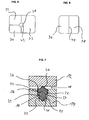
- FIG. 7 shows a seal 10 according to the invention in cross section.
- the seal 10 according to the invention comprises a sealing body 16 which is placed or arranged between a first component 12 and a second component 14 and in particular is inserted in a groove 26 formed in the second component 14.
- the seal body 16 seals a gap 18 formed by the first and second members 12, 14 including the groove 26.
- the first and second component 12 and 14 may be any components of a pneumatic or hydraulic system that separate pressure-tight together with the seal 10 at least two different pressure chambers.
- the sealing body 16 is substantially T-shaped and comprises two sealing portions 20 at the top and bottom, which are formed in the form of a semicircle in the seal body cross-section.
- a sealing portion 20 of the sealing body 16 (the upper sealing portion 20 in FIG. 7 ) is in pressure-tight contact with the first component 12, whereas the second sealing portion 20 of the sealing body 16 (the lower sealing portion 20 in FIG. 7 ) is in pressure-tight contact with a groove bottom of the groove 26.
- the sealing body 16 comprises four guide portions 22, each loaded with groove walls of the groove 26 in and / or unloaded state of the seal body 16 are in contact. Based on the guide portions 22, the sealing body 16 is movable along the groove walls, but not about an axis perpendicular to the cross section of the seal body 16 rotatable or tiltable.
- two equalizing portions 24 in the form of a recess on the seal body 24 are provided in cross section of the seal body 16.
- the compensation sections 24 are each provided between two guide sections 22 of the sealing body 16, which are each guided by the same groove wall.
- the sealing body 16 can firstly be compressed in the direction of the groove base within a certain play and simultaneously guided.
- these compensation sections 24 provide a material compensation space due to the recess. As a result, material compensation in the direction of the recess can take place when the sealing body 16 is compressed, compressed or loaded.
- the sealing body 16 of the seal 10 is first inserted into the groove 26.
- the sealing body 16 via the guide portions 22 in interaction with the groove walls of the groove 26 further into the Groove 26 introduced.
- the first and second components 12, 14 are brought together or joined together, whereby the sealing portions 20 of the sealing body 16 with the first component 12 and the second component 14 come into contact. The farther the first and second components 12, 14 are guided against each other, the greater becomes a surface pressure between the first, second component 12, 14 and the respective sealing portion 20 of the sealing body 16.
- the space created by the compensating sections 24 between the sealing body 16 and the groove walls of the groove 16 for balancing the material of the sealing body is the compensating portions 24 during assembly of the first and second component 12, 14 first 16 used in compressed seal 10. Tilting of the seal body 16 is continuously suppressed due to the guide portions 22 during the assembly of the components 12, 14.
Description
Die Erfindung betrifft eine Dichtungsanordnung umfassend ein Bauteil mit einer Aussparung und eine Dichtung mit einem Dichtungskörper, der zumindest einen Dichtabschnitt umfasst, wobei der Dichtungskörper weiterhin zwei Führungsabschnitte in einem oberen Bereich und zwei andere Führungsabschnitte in einem unteren Bereich umfasst, wobei sich die vier Führungsabschnitte von dem Dichtabschnitt unterscheiden und der Dichtungskörper von den vier Führungsabschnitten in einem belasteten und/oder unbelasteten Zustand in der Aussparung geführt wird.The invention relates to a sealing arrangement comprising a component having a recess and a seal having a sealing body, which comprises at least one sealing section, wherein the sealing body further comprises two guide sections in an upper region and two other guide sections in a lower region, wherein the four guide sections of distinguish the sealing portion and the seal body is guided by the four guide portions in a loaded and / or unloaded state in the recess.
Weiterhin bezieht sich die Erfindung auf ein Verfahren zum Abdichten eines Zwischenraums anhand einer Dichtung, der durch zumindest zwei Bauteile ausgebildet wird, wobei die Dichtung einen Dichtungskörper umfasst, der zum Abdichten des Zwischenraums in den Zwischenraum platziert wird und der zumindest einen Dichtabschnitt umfasst, über den der Zwischenraum abgedichtet wird, wobei der Dichtungskörper weiterhin zwei Führungsabschnitte in einem oberen Bereich und zwei andere Führungsabschnitte in einem unteren Bereich umfasst, wobei sich die vier Führungsabschnitte von dem Dichtabschnitt unterscheiden und der Dichtungskörper von den vier Führungsabschnitten in einem belasteten und/oder unbelasteten Zustand in dem Zwischenraum geführt wird.Furthermore, the invention relates to a method for sealing a gap by means of a seal, which is formed by at least two components, wherein the seal comprises a sealing body, which is placed for sealing the gap in the gap and which comprises at least one sealing portion, over the the space is sealed, wherein the sealing body further comprises two guide portions in an upper portion and two other guide portions in a lower portion, wherein the four guide portions are different from the sealing portion, and the seal body is guided by the four guide portions in a loaded and / or unloaded state in the gap.
Darüber hinaus betrifft die Erfindung eine Bauteilbaugruppe und eine Verwendung der Dichtungsanordnung beziehungsweise der Bauteilgruppe.Moreover, the invention relates to a component assembly and a use of the seal assembly or the component group.
Die
Die
Die
Die
Die
Gattungsgemäße Dichtungsanordnungen sind bereits aus dem Stand der Technik bekannt. Beispielsweise werden derartige Dichtungsanordnungen in Verbindung mit pneumatischen oder hydraulischen Systemen eingesetzt, bei denen unterschiedliche Druckniveaus in unterschiedlichen durch die Dichtung voneinander getrennten Druckräumen aufrechterhalten werden müssen. Die dabei verwendeten, dem Stand der Technik angehörenden Dichtungen können unterschiedliche Querschnitte aufweisen, wie insbesondere aus den
Je nach Komplexität des pneumatischen oder hydraulischen Systems können die Dichtungsverläufe der Dichtungen 10I, II, III, IV variieren und dementsprechend unterschiedlich komplex sein. Die
Der Erfindung liegt daher die Aufgabe zugrunde, die gattungemäßen Dichtungen, Verfahren zum Abdichten von Zwischenräumen, Bauteile mit Aussparungen sowie Bauteilgruppen derart weiterzubilden, dass die vorgenannten Nachteile zumindest teilweise überwunden werden können.The invention is therefore the object of the generic type seals, methods for sealing gaps, components with recesses and component groups in such a way that the aforementioned disadvantages can be overcome at least partially.
Diese Aufgabe wird durch die Merkmale der unabhängigen Ansprüche gelöst.This object is solved by the features of the independent claims.
Vorteilhafte Ausgestaltungen und Weiterbildungen der Erfindung ergeben sich aus den abhängigen Ansprüchen.Advantageous embodiments and modifications of the invention will become apparent from the dependent claims.
Die erfindungsgemäße Dichtungsanordnung baut auf dem gattungsgemäßen Stand der Technik dadurch auf, dass der Dichtungskörper im Wesentlichen einen T-förmigen Querschnitt aufweist, wobei die zwei Führungsabschnitte in dem oberen Bereich durch Stirnflächen eines T-Balkens des T-förmigen Querschnitts und die zwei anderen Führungsabschnitte in dem unteren Bereich durch Seitenflanken eines T-Fußes des T-förmigen Querschnitts ausgebildet sind. Der Dichtungskörper umfasst zumindest einen sich von dem Dichtabschnitt unterscheidenden Führungsabschnitt, über den der Dichtungskörper in einem belasteten und/oder unbelasteten Zustand in dem Zwischenraum geführt wird. Diese Ausgestaltung des Dichtungskörpers beruht auf der Erkenntnis, eine Unterteilung des Dichtungskörpers in funktionell unterschiedliche Abschnitte vorzunehmen, um die vorgenannten Nachteile zu überwinden. Da der Dichtungskörper durch dessen Führungsabschnitt in dem Zwischenraum geführt wird, kann insbesondere eine Verkippung des Dichtungskörpers verhindert werden. Gleichzeitig dichtet der Dichtungskörper den Zwischenraum im belasteten und abdichtenden Zustand durch dessen Dichtabschnitte ab, während die Verkippung aufgrund der Führung verhindert wird. Anhand der funktionellen Unterteilung des Dichtungskörpers ergibt sich eine Geometrie des Dichtungskörpers, die die Stärken der bestehenden Querschnittsformen der dem Stand der Technik angehörenden Dichtungen vereint, jedoch ohne die zuvor beschriebenen Nachteile aufzuweisen. Der Querschnitt des Dichtungskörpers wird vorzugsweise in unterschiedliche Funktionsabschnitte unterteilt, nämlich in den Dichtabschnitt, den Führungsabschnitt und in einen Ausgleichsabschnitt. Diese funktionale Trennung ermöglicht eine optimale und individuelle Gestaltung der einzelnen Abschnitte des Dichtungskörpers. Insbesondere in dem Fall, bei dem die Dichtung in eine an einem der Bauteile ausgebildete Nut eingesetzt ist, ist auch die Nutquerschnittsgeometrie an die Querschnittsform der erfindungsgemäßen Dichtung funktionell angepasst; damit beruht die Wirkung der Querschnittsformen auf dem Zusammenspiel von Nut- und Dichtungsquerschnitt. Vorzugsweise wird der Dichtabschnitt des Dichtkörpers im Querschnitt kreisförmig oder halbkreisförmig jeweils an der Dichtungsober- und -unterseite ausgebildet. Dadurch kann die Flächenpressung unter anderem auch über weite Bereiche durch die Wahl des Kopf- und Fußradius an der Ober- und Unterseite der Dichtung eingestellt werden. Darüber hinaus kann der Dichtungskörper über den Führungsabschnitt eng geführt werden, da der Führungsabschnitt unabhängig von dem Ausgleichsabschnitt ist. Vorzugsweise wird der Dichtungskörper derart ausgeführt, dass er zumindest zwei Führungsabschnitte und zwei Dichtabschnitte umfasst, wobei die Führungsabschnitte in einem größtmöglichen Abstand voneinander angeordnet sind. Beispielsweise kann der eine Führungsabschnitt in einem oberen Bereich des Dichtungskörpers nahe dem oberen Dichtabschnitt liegen, während der andere Führungsabschnitt in einem unteren Bereich des Dichtungskörpers nahe dem unteren Dichtabschnitt vorgesehen ist. Zum Beispiel können die Führungsabschnitte direkt angrenzend an einer jeweiligen Dichtfläche des entsprechenden Dichtabschnitts vorgesehen sein. Damit wird die Führung des Dichtungskörpers durch die zwei voneinander unabhängigen Führungsbereiche gewährleistet. Somit wird ein Verkippen des Dichtungskörpers aufgrund dessen Führungsabschnitts unterbunden. Dabei ist die erfindungsgemäße Dichtungsanordnung für alle Dichtungsverläufe mit mindestens zwei Stoßbereichen geeignet, d.h. für mindestens zwei verschiedene Druckräume. Der Dichtungsverlauf kann völlig beliebig sein.The sealing arrangement according to the invention builds on the generic state of the art in that the sealing body has a substantially T-shaped cross-section, wherein the two guide sections in the upper region by end faces of a T-beam of the T-shaped cross-section and the two other guide sections in the lower portion are formed by side edges of a T-leg of the T-shaped cross section. Of the Sealing body comprises at least one different from the sealing portion guide portion over which the seal body is guided in a loaded and / or unloaded state in the intermediate space. This embodiment of the seal body is based on the knowledge to make a subdivision of the seal body into functionally different sections in order to overcome the aforementioned disadvantages. Since the sealing body is guided by the guide portion in the intermediate space, in particular a tilting of the sealing body can be prevented. At the same time, the seal body seals the gap in the loaded and sealed state by its sealing portions, while the tilting is prevented due to the guide. Based on the functional subdivision of the sealing body results in a geometry of the sealing body, which combines the strengths of the existing cross-sectional shapes of the prior art belonging seals, but without having the disadvantages described above. The cross section of the sealing body is preferably subdivided into different functional sections, namely the sealing section, the guide section and a compensating section. This functional separation allows an optimal and individual design of the individual sections of the seal body. In particular, in the case where the seal is inserted into a groove formed on one of the components, the groove cross-sectional geometry is also functional on the cross-sectional shape of the seal according to the invention customized; Thus, the effect of the cross-sectional shapes is based on the interaction of groove and sealing cross-section. Preferably, the sealing portion of the sealing body is formed in cross-section circular or semi-circular respectively at the sealing upper and -unterseite. As a result, the surface pressure can also be adjusted over a wide range by selecting the head and foot radius at the top and bottom of the seal. Moreover, since the guide portion is independent of the balancing portion, the sealing body can be tightly guided over the guide portion. Preferably, the sealing body is designed such that it comprises at least two guide portions and two sealing portions, wherein the guide portions are arranged at a maximum distance from each other. For example, the one guide portion may be located in an upper portion of the seal body near the upper seal portion, while the other guide portion is provided in a lower portion of the seal body near the lower seal portion. For example, the guide portions may be provided directly adjacent to a respective sealing surface of the corresponding sealing portion. Thus, the leadership of the seal body is ensured by the two independent management areas. Thus, tilting of the seal body due to the guide portion thereof is suppressed. In this case, the sealing arrangement according to the invention is suitable for all sealing courses with at least two joint areas, ie for at least two different ones Pressure chambers. The course of the seal can be completely arbitrary.
Die erfindungsgemäße Dichtungsanordnung kann in vorteilhafter Weise derart weitergebildet werden, dass der Dichtungskörper weiterhin zumindest einen Ausgleichsabschnitt umfasst, der benachbart zum Führungsabschnitt sowie zum Dichtabschnitt angeordnet und in der Form einer Aussparung ausgebildet ist. Dadurch wird ermöglicht, dass bei belasteter, zusammengedrückter und somit abdichtender Dichtung ein Materialausgleich in den durch die Aussparung zur Verfügung gestellten Raum zwischen dem Dichtungskörper und beispielsweise den Nutwänden erfolgen kann.The sealing arrangement according to the invention can be developed in an advantageous manner such that the sealing body further comprises at least one compensating section, which is arranged adjacent to the guide section and the sealing section and formed in the form of a recess. This makes it possible that when loaded, compressed and thus sealing seal material compensation in the space provided by the recess space between the seal body and, for example, the groove walls can be done.
Die erfindungsgemäße Dichtungsanordnung wird so verwirklicht, dass der Dichtungskörper im Wesentlichen einen T-förmigen Querschnitt aufweist. Eine derartige Querschnittsgeometrie in T-Form mit entsprechend ausgestalteter Dichtnut, in die der Dichtungskörper eingesetzt werden kann, trägt zur Verbesserung der Dichtwirkung bei komplexen Dichtungsverläufen mit mindestens zwei unterschiedlichen, gegeneinander abzudichtenden Druckräumen bei. Selbstverständlich können beliebige Formen für den Dichtungskörper verwendet werden, solange die vorstehend erläuterte funktionale Trennung der Abschnitte des Dichtungskörpers vorgenommen wird.The seal assembly according to the invention is realized so that the seal body has a substantially T-shaped cross-section. Such a cross-sectional geometry in T-shape with appropriately designed sealing groove into which the sealing body can be used contributes to the improvement of the sealing effect in complex sealing processes with at least two different pressure chambers to be sealed against each other. Of course, any shapes may be used for the seal body, as long as the above-described functional separation of the portions of the seal body is made.
Weiterhin kann die erfindungsgemäße Dichtungsanordnung derart ausgebildet werden, dass der Dichtungskörper in eine den Zwischenraum zumindest teilweise ausbildende Nut in einem oder beiden Bauteilen platzierbar ist, wobei der Führungsabschnitt des Dichtungskörpers in der Nut im belasteten und/oder unbelasteten Zustand des Dichtungskörpers geführt wird. Dadurch wird insbesondere ein verbessertes Toleranzausgleichsvermögen erzielt, das die entsprechende Nut größere Toleranzen aufweisen kann. Auch können dadurch kostengünstigere Fertigungsverfahren erzielt werden. Weiterhin kann die Montage des Dichtungskörpers durch relativ großzügige Einführschrägen an der Nut stark vereinfacht werden. Darüber hinaus kann durch partielles Aufdicken beziehungsweise Verstärken des Dichtungskörpers in den Stoßbereichen zum einen die Führung weiter verbessert und zum anderen ein Herausfallen des Dichtungskörpers aus der Nut, zum Beispiel bei einer Vormontage, verhindert werden.Furthermore, the sealing arrangement according to the invention can be formed such that the sealing body can be placed in a groove forming at least partially in one or both components, wherein the guide portion of the sealing body is guided in the groove in the loaded and / or unloaded state of the sealing body. As a result, in particular an improved tolerance compensation capability is achieved, which can have the corresponding groove larger tolerances. Also, this can be achieved by cheaper manufacturing processes. Furthermore, the assembly of the sealing body can be greatly simplified by relatively generous insertion bevels on the groove. In addition, by partially thickening or reinforcing the sealing body in the joint areas on the one hand further improves the leadership and on the other falling out of the seal body from the groove, for example, in a pre-assembly, can be prevented.
In diesem Zusammenhang ist es besonders vorteilhaft, die erfindungsgemäße Dichtung so zu verwirklichen, dass der Führungsabschnitt des Dichtungskörpers beidseitig an Nutwänden der Nut im belasteten und/oder unbelasteten Zustand des Dichtungskörpers geführt wird. Im Falle von mehreren Führungsabschnitten des Dichtungskörpers je Nutwand können diese beispielsweise von dem Ausgleichsabschnitt, insbesondere der Aussparung, voneinander beabstandet sein.In this context, it is particularly advantageous to realize the seal of the invention so that the guide portion of the seal body is guided on both sides of groove walls of the groove in the loaded and / or unloaded state of the seal body. In the case of several guide sections of the sealing body per groove wall, these can be spaced from one another, for example, by the compensating section, in particular the recess.
Das erfindungsgemäße Verfahren baut auf dem gattungsgemäβen Stand der Technik dadurch auf, dass der Dichtungskörper mit im Wesentlichen T-förmigen Querschnitt in den Zwischenraum platziert wird, wobei die zwei Führungsabschnitte in dem oberen Bereich durch Stirnflächen eines T-Balkens des T-förmigen Querschnitts und die zwei anderen Führungsabschnitte in dem unteren Bereich durch Seitenflanken eines T-Fußes des T-förmigen Querschnitts ausgebildet sind.Dadurch ergeben sich die im Zusammenhang mit der erfindungsgemäßen Dichtung erläuterten Eigenschaften und Vorteile in gleicher oder ähnlicher Weise, weshalb zur Vermeidung von Wiederholungen auf die entsprechenden Ausführungen im Zusammenhang mit der erfindungsgemäßen Dichtung verwiesen wird.The inventive method is based on the generic state of the art in that the sealing body is placed with a substantially T-shaped cross section in the gap, wherein the two guide portions in the upper region by end faces of a T-beam of the T-shaped cross-section and the two other guide sections in the lower region are formed by side flanks of a T-shaped T-shaped cross-section. The properties and advantages explained in connection with the inventive seal thus result in the same or a similar manner, and so avoid repetition of the corresponding embodiments in connection with the seal according to the invention is referenced.
Gleiches gilt sinngemäß für die folgenden bevorzugten Ausführungsformen des erfindungsgemäßen Verfahrens, wobei zur Vermeidung von Wiederholungen auch diesbezüglich auf die entsprechenden Ausführungen im Zusammenhang mit der erfindungsgemäßen Dichtung verwiesen wird.The same applies mutatis mutandis to the following preferred embodiments of the method according to the invention, reference being made to avoid repetition in this regard to the corresponding statements in connection with the seal according to the invention.
Bevorzugt wird das erfindungsgemäße Verfahren so weitergebildet, dass der Dichtungskörper durch zumindest einen benachbart zum Führungsabschnitt sowie zum Dichtabschnitt und in der Form einer Aussparung ausgebildeten Ausgleichsabschnitt einen Materialausgleich aufgrund einer Verformung des Dichtungskörpers im belasteten Zustand bewirkt.Preferably, the method according to the invention is developed such that the sealing body effects a compensation of material due to a deformation of the sealing body in the loaded state by at least one compensating section adjacent to the guide section and the sealing section and in the form of a recess.
Das erfindungsgemäße Verfahren wird derart umgesetzt, dass der Dichtungskörper mit im Wesentlichen T-förmigen Querschnitt in den Zwischenraum platziert wird.The inventive method is implemented such that the sealing body is placed with a substantially T-shaped cross-section in the gap.
Darüber hinaus kann das erfindungsgemäße Verfahren so weitergebildet werden, dass der Dichtungskörper in eine den Zwischenraum zumindest teilweise ausbildende Nut in einem oder beiden Bauteilen platziert wird, wobei der Führungsabschnitt des Dichtungskörpers in der Nut im belasteten und/oder unbelasteten Zustand des Dichtungskörpers geführt wird.In addition, the inventive method can be developed so that the sealing body is placed in a gap forming at least partially groove in one or both components, wherein the guide portion of the seal body is guided in the groove in the loaded and / or unloaded state of the seal body.
Im Rahmen dieser Weiterbildung kann das erfindungsgemäße Verfahren derart ausgeführt werden, dass der Führungsabschnitt des Dichtungskörpers beidseitig an Nutwänden der Nut im belasteten und/oder unbelasteten Zustand des Dichtungskörpers geführt wird.In the context of this development, the method according to the invention can be carried out such that the guide section of the sealing body is guided on both sides on groove walls of the groove in the loaded and / or unloaded state of the sealing body.
Die Aussparung des Bauteils ist derart gestaltet, dass sie den erfindungsgemäßen Dichtungskörper an den vier sich von einem Dichtabschnitt des Dichtungskörpers unterscheidenden Führungsabschnitten des Dichtungskörpers führt.The recess of the component is designed such that it guides the sealing body according to the invention at the four different from a sealing portion of the seal body guide portions of the seal body.
Auch in diesem Fall ergeben sich die im Zusammenhang mit der erfindungsgemäßen Dichtung erläuterten Eigenschaften und Vorteile in gleicher oder ähnlicher Weise, weshalb zur Vermeidung von Wiederholungen auf die entsprechenden Ausführungen im Zusammenhang mit der erfindungsgemäßen Dichtungsanordnung verwiesen wird. Gleiches gilt ebenso für die bevorzugten Ausführungen des erfindungsgemäßen Bauteils.In this case too, the properties and advantages explained in connection with the gasket according to the invention result in the same or a similar manner, which is why, in order to avoid repetition, reference is made to the corresponding statements in connection with the invention Sealing arrangement is referenced. The same applies equally to the preferred embodiments of the component according to the invention.
Das erfindungsgemäße Bauteil kann in vorteilhafter Weise derart weitergebildet werden, dass die Aussparung eine Nut ist.The component according to the invention can be developed in an advantageous manner such that the recess is a groove.
Weiterhin kann das erfindungsgemäße Bauteil so ausgebildet werden, dass zumindest Abschnitte von Nutwänden der Nut den Dichtungskörper zumindest teilweise führen.Furthermore, the component according to the invention can be formed such that at least portions of groove walls of the groove guide the sealing body at least partially.
Darüber hinaus kann das erfindungsgemäße Bauteil derart verwirklicht werden, dass zumindest ein Abschnitt eines Nutgrunds der Nut mit dem Dichtabschnitt des Dichtungskörpers in Berührung steht.In addition, the component according to the invention can be realized such that at least a portion of a groove bottom of the groove is in contact with the sealing portion of the seal body.
Die erfindungsgemäße Bauteilbaugruppe umfasst zumindest eine erfindungsgemäße Dichtungsanordnung und zumindest ein weiteres Bauteil, wobei das weitere Bauteil nahe dem ersten Bauteil angeordnet ist, um einen durch die erfindungsgemäße Dichtungsanordnung abgedichteten Zwischenraum auszubilden. Dadurch werden die im Zusammenhang mit der erfindungsgemäßen Dichtungsanordnung genannten Vorteile auf gleiche oder ähnliche Weise erzielt.The component assembly according to the invention comprises at least one sealing arrangement according to the invention and at least one further component, wherein the further component is arranged close to the first component in order to form a gap sealed by the sealing arrangement according to the invention. As a result, the advantages mentioned in connection with the sealing arrangement according to the invention are achieved in the same or similar manner.
Die Erfindung wird nun mit Bezug auf die begleitenden Zeichnungen anhand bevorzugter Ausführungsformen beispielhaft erläutert.The invention will now be described by way of example with reference to the accompanying drawings with reference to preferred embodiments.
Es zeigen:
- Figur 1
- ein erstes Beispiel einer dem Stand der Technik angehörenden Dichtung im Querschnitt;
- Figur 2
- ein zweites Beispiel einer dem Stand der Technik angehörenden Dichtung im Querschnitt;
- Figur 3
- ein drittes Beispiel einer dem Stand der Technik angehörenden Dichtung im Querschnitt;
- Figur 4
- ein viertes Beispiel einer dem Stand der Technik angehörenden Dichtung im Querschnitt;
- Figur 5
- einen Dichtungsverlauf einer Dichtung;
- Figur 6
- einen weiteren Dichtungsverlauf einer Dichtung; und
- Figur 7
- eine erfindungsgemäße Dichtung im Querschnitt.
- FIG. 1
- a first example of a prior art belonging seal in cross section;
- FIG. 2
- a second example of a prior art belonging seal in cross section;
- FIG. 3
- a third example of a prior art seal in cross-section;
- FIG. 4
- a fourth example of a prior art seal in cross section;
- FIG. 5
- a sealing course of a seal;
- FIG. 6
- another seal course of a seal; and
- FIG. 7
- a seal according to the invention in cross section.
Im Zusammenhang mit der Durchführung des erfindungsgemäßen Verfahrens zur Abdichtung des Zwischenraums 18 zwischen dem ersten und zweiten Bauteil 12, 14 wird der Dichtungskörper 16 der erfindungsgemäßen Dichtung 10 zunächst in die Nut 26 eingesetzt. Dabei wird der Dichtungskörper 16 über dessen Führungsabschnitte 22 im Zusammenspiel mit den Nutwänden der Nut 26 weiter in die Nut 26 eingeführt. Nach dem Einführen des Dichtungskörpers 16 in die Nut 26 werden das erste und zweite Bauteil 12, 14 aneinandergeführt beziehungsweise zusammengefügt, wodurch die Dichtabschnitte 20 des Dichtkörpers 16 mit dem ersten Bauteil 12 und dem zweiten Bauteil 14 in Berührung treten. Je weiter das erste und zweite Bauteil 12, 14 aneinander geführt wird, umso größer wird eine Flächenpressung zwischen dem ersten, zweiten Bauteil 12, 14 und dem jeweiligen Dichtabschnitt 20 des Dichtungskörpers 16. Damit erhöht sich auch die Dichtungswirkung der erfindungsgemäßen Dichtung 10. Weiterhin ermöglichen die Ausgleichsabschnitte 24 beim Zusammenfügen des ersten und zweiten Bauteils 12, 14 zunächst eine weitere Bewegung der Führungsabschnitte 22 in Richtung des Nutgrunds der Nut 26. Zusätzlich wird der durch die Ausgleichsabschnitte 24 geschaffene Raum zwischen Dichtungskörper 16 und den Nutwänden der Nut 16 zum Materialausgleich des Dichtungskörpers 16 bei zusammengedrückter Dichtung 10 verwendet. Ein Verkippen des Dichtungskörpers 16 wird aufgrund der Führungsabschnitte 22 während des Zusammenfügens der Bauteile 12, 14 fortwährend unterbunden.In connection with the implementation of the method according to the invention for sealing the
Die in der vorstehenden Beschreibung, in den Zeichnungen sowie in den Ansprüchen offenbarten Merkmale der Erfindung können sowohl einzeln als auch in beliebiger Kombination für die Verwirklichung der Erfindung wesentlich sein.The features of the invention disclosed in the foregoing description, in the drawings and in the claims may be essential to the realization of the invention both individually and in any combination.
- 10I,II,III,IV 10 I, II, III, IV
- Dichtungpoetry
- 12I,II,III,IV 12 I, II, III, IV
- erstes Bauteilfirst component
- 14I,II,III,IV 14 I, II, III, IV
- zweites Bauteilsecond component
- 24 IV 24 IV
- AusparungAusparung
- 26I,II,III,IV 26 I, II, III, IV
- Nutgroove
- 1010
- Dichtungpoetry
- 1212
- erstes Bauteilfirst component
- 1414
- zweites Bauteilsecond component
- 1616
- Dichtungskörperseal body
- 1818
- Zwischenraumgap
- 2020
- Dichtabschnittsealing portion
- 2222
- Führungsabschnittguide section
- 2424
- Ausgleichsabschnittcompensation section
- 2626
- Nutgroove
- 2828
- Dichtungsverlaufseal course
- 3030
- Druckraumpressure chamber
- 3232
- Druckraumpressure chamber
- 3434
- Druckraumpressure chamber
- 3636
- Druckraumpressure chamber
- 3838
- Druckraumpressure chamber
- 4040
- Dichtungsverlaufseal course
- 4242
- Druckraumpressure chamber
Claims (11)
- Seal arrangement, comprising a component (14) having a recess (26) and a seal (10) with a seal body (16), for sealing a gap (18) which can form between at least the component (14) and a further component (12), which is represented by the two components (12, 14) including the recess (26) and which includes at least one sealing section (20) by means of which the gap (18) is sealed in the assembled state, wherein the body (16) further comprises two guide sections (22) in an upper region and two further guide sections (22) in a lower region, wherein the four guide sections (22) differ from the sealing section (20) und the seal body (16) is guided by the four guide sections (22) in the recess (26) in a loaded and/or a no-load condition, characterised in that the seal body (16) has a substantially T-shaped cross-section, wherein the two guide sections (22) in the upper region are represented by end faces of a T-bar of the T-shaped cross-section and the two further guide sections (22) in the lower region are represented by lateral flanks of a T-foot of the T-shaped cross-section.
- Seal arrangement according to claim 1, characterised in that the recess (26) is a groove.
- Seal arrangement according to claim 1 or 2, characterised in that the seal body (16) further comprises at least one compensation section (24), which is located adjacent to a guide section (22) and to the sealing section (20) and which is designed in the form of a recess.
- Seal arrangement according to claim 2 or 3, characterised in that at least one section of a bottom of the groove (26) is in contact with the sealing section (20) of the seal body (16).
- Component assembly comprising at least one seal arrangement according to any of claims 1 to 4, characterised in that the component assembly comprises at least one further component (12), the further component (12) being arranged close to the component (14) to form a gap (18) sealed by the seal (10).
- Use of the device according to any of claims 1 to 5, wherein the seal body (16) is placed into a groove (26) in one or both of the components, which groove at least partially forms the gap (18), in order to seal a gap (18) between the component (14) and a further component (12).
- Use of the seal arrangement (10) according to claim 6, characterised in that the guide section (22) of the seal body (16) is guided on both sides on walls of the groove (26) in the loaded and/or the no-load condition of the seal body (16).
- Method for sealing a gap (18) using a seal (10), which gap (18) is formed by at least two components (12, 14), wherein the seal (10) comprises a seal body (16) which is placed into the gap (18) for sealing the gap (18) and which comprises at least one sealing section (20) by means of which the gap (18) is sealed, wherein the seal body (16) further comprises two guide sections (22) in an upper region and two further guide sections (22) in a lower region, wherein the four guide sections (22) differ from the sealing section (20) und the seal body (16) is guided by the four guide sections (22) in the recess (26) in a loaded and/or a no-load condition, characterised in that the seal body (16) with its substantially T-shaped cross-section is placed into the gap (18), wherein the two guide sections (22) in the upper region are represented by end faces of a T-bar of the T-shaped cross-section and the two further guide sections (22) in the lower region are represented by lateral flanks of a T-foot of the T-shaped cross-section.
- Method according to claim 8, characterised in that the seal body (16) effects a material compensation based on a deformation of the seal body (16) in the loaded condition by means of at least one compensation section (24), which is located adjacent to a guide section (22) and to the sealing section (20) and which is designed in the form of a recess.
- Method according to claim 8 or 9, characterised in that the Seal body (16) is placed into a groove (26) in one or both of the components, which groove at least partially forms the gap (18), the guide section (22) of the seal body (16) being guided in the groove (26) in the loaded and/or the no-load condition of the seal body (16).
- Method according to claim 10, characterised in that the guide section (22) of the seal body (16) is guided on both sides on walls of the groove (26) in the loaded and/or the no-load condition of the seal body (16).
Applications Claiming Priority (1)
| Application Number | Priority Date | Filing Date | Title |
|---|---|---|---|
| DE200710032971 DE102007032971A1 (en) | 2007-07-16 | 2007-07-16 | Seal and method for sealing a gap, and component and component group for receiving a seal |
Publications (3)
| Publication Number | Publication Date |
|---|---|
| EP2017508A2 EP2017508A2 (en) | 2009-01-21 |
| EP2017508A3 EP2017508A3 (en) | 2010-12-08 |
| EP2017508B1 true EP2017508B1 (en) | 2013-09-11 |
Family
ID=39876837
Family Applications (1)
| Application Number | Title | Priority Date | Filing Date |
|---|---|---|---|
| EP20080012345 Active EP2017508B1 (en) | 2007-07-16 | 2008-07-09 | Sealing arrangement and method for sealing off an interval as well as component assembly for holding a seal |
Country Status (2)
| Country | Link |
|---|---|
| EP (1) | EP2017508B1 (en) |
| DE (1) | DE102007032971A1 (en) |
Cited By (2)
| Publication number | Priority date | Publication date | Assignee | Title |
|---|---|---|---|---|
| USD816209S1 (en) | 2016-03-28 | 2018-04-24 | 3M Innovative Properties Company | Respirator inlet port connection seal |
| USD827810S1 (en) | 2016-03-28 | 2018-09-04 | 3M Innovative Properties Company | Hardhat suspension adapter for half facepiece respirators |
Families Citing this family (7)
| Publication number | Priority date | Publication date | Assignee | Title |
|---|---|---|---|---|
| DE102011050465A1 (en) * | 2011-05-18 | 2012-11-22 | Geiger Automotive Gmbh | Sealing system for sealing e.g. liquid lines of cooling water regulator in car, has sealing ring exhibiting oval cross-section and comprising envelope with oval cross-section, where cross-sections of ring and/or envelope comprise two axles |
| DE102013217147A1 (en) * | 2013-08-28 | 2015-03-05 | Dichtungstechnik G. Bruss Gmbh & Co. Kg | Profile sealing ring and sealing arrangement |
| US9814913B2 (en) | 2013-11-15 | 2017-11-14 | 3M Innovative Properties Company | Respirator with floating elastomeric sleeve |
| DE202014002468U1 (en) * | 2014-03-19 | 2015-06-25 | Robert Bosch Gmbh | Gear machine with rectangular cover gasket |
| WO2017172358A1 (en) | 2016-03-28 | 2017-10-05 | 3M Innovative Properties Company | Respirator fit check sealing devices and methods |
| USD842982S1 (en) | 2016-03-28 | 2019-03-12 | 3M Innovative Properties Company | Hardhat suspension adapter for half facepiece respirators |
| EP3436163B1 (en) | 2016-03-28 | 2020-08-19 | 3M Innovative Properties Company | Multiple chamber respirator sealing devices and methods |
Family Cites Families (11)
| Publication number | Priority date | Publication date | Assignee | Title |
|---|---|---|---|---|
| US2604507A (en) * | 1945-08-09 | 1952-07-22 | Bendix Aviat Corp | Shielding closure means |
| FR2669703B1 (en) * | 1990-11-26 | 1993-01-15 | Pu Sa | STATIC SEAL. |
| DE4205442A1 (en) * | 1991-05-18 | 1992-11-26 | Technoprofil Breidenbach & Bla | Gasket section of rubber elastic material esp. foam rubber - seals gap between two structural parts e.g. respectively lamp cover glass and housing of spray-surge water protection lamp |
| US5551705A (en) * | 1995-07-12 | 1996-09-03 | Fel-Pro Incorporated | Double beaded spaghetti seal with stiffness increasing deformation behavior |
| JPH10267141A (en) * | 1997-03-21 | 1998-10-09 | Smc Corp | Spool |
| DE19736431C2 (en) * | 1997-08-21 | 2003-01-02 | Bruss Dichtungstechnik | Static sealing arrangement |
| DE19736467C2 (en) * | 1997-08-21 | 2003-06-12 | Bruss Dichtungstechnik | Static seal |
| JPH11126648A (en) * | 1997-10-21 | 1999-05-11 | Yazaki Corp | Packing holding structure |
| US6065757A (en) * | 1998-07-02 | 2000-05-23 | Caterpillar Inc. | Flywheel housing |
| WO2002093045A1 (en) * | 2001-05-11 | 2002-11-21 | Msa Auer Gmbh | Annular seal, in particular for plug-in connectors |
| DE10349921B4 (en) * | 2003-10-25 | 2017-03-09 | Carl Freudenberg Kg | poetry |
-
2007
- 2007-07-16 DE DE200710032971 patent/DE102007032971A1/en not_active Ceased
-
2008
- 2008-07-09 EP EP20080012345 patent/EP2017508B1/en active Active
Cited By (2)
| Publication number | Priority date | Publication date | Assignee | Title |
|---|---|---|---|---|
| USD816209S1 (en) | 2016-03-28 | 2018-04-24 | 3M Innovative Properties Company | Respirator inlet port connection seal |
| USD827810S1 (en) | 2016-03-28 | 2018-09-04 | 3M Innovative Properties Company | Hardhat suspension adapter for half facepiece respirators |
Also Published As
| Publication number | Publication date |
|---|---|
| DE102007032971A1 (en) | 2009-02-05 |
| EP2017508A2 (en) | 2009-01-21 |
| EP2017508A3 (en) | 2010-12-08 |
Similar Documents
| Publication | Publication Date | Title |
|---|---|---|
| EP2017508B1 (en) | Sealing arrangement and method for sealing off an interval as well as component assembly for holding a seal | |
| EP2035732B1 (en) | Seal and seal arrangement | |
| EP1621736B2 (en) | Wall structure for a hot gas flow path | |
| DE2055881A1 (en) | Ring seal | |
| CH660407A5 (en) | SEALING RING FOR PISTON RODS. | |
| DE4007252A1 (en) | SEALING ARRANGEMENT FOR A COMPRESSOR PISTON | |
| DE102010051403A1 (en) | Seal and method for producing a sealing ring | |
| EP3071797B1 (en) | Sealing assembly for sealing a gap between two components lying flat next to each other at room temperature | |
| DE102014105555A1 (en) | Connection for corrugated pipes | |
| DE102017001269A1 (en) | Filter element and filter assembly | |
| EP1241388B1 (en) | Elastic deformable bellow and method of producing such a bellow | |
| EP1945985B1 (en) | Connecting system for conduits, fittings or assemblies | |
| WO2016058767A1 (en) | Method for connecting a separating plate of a vibration damper to a cylinder, vibration damper, and motor vehicle | |
| EP1500853B1 (en) | Sealing with a variable internal diameter | |
| WO2019038319A1 (en) | Cylinder head gasket | |
| EP3188919B2 (en) | Door sealing device, door sealing system, and door leaf for a rail vehicle | |
| WO2013075884A1 (en) | Cylinder, in particular hydraulic cylinder for the deep sea | |
| DE3825916A1 (en) | RING SEAL | |
| EP1369626B1 (en) | Sealing element | |
| DE102015106163A1 (en) | Piston-cylinder arrangement for a piston compressor with a special dynamically sealing piston ring | |
| DE3505761C1 (en) | Pit stamp seal assembly | |
| BE1028293B1 (en) | High-pressure sealing arrangement and high-pressure system for the radial sealing of a container closure of a high-pressure container and their use | |
| DE102019215159B4 (en) | Adjusting piston and adjustment device | |
| DE112014002728T5 (en) | sealing system | |
| DE102015001571B4 (en) | Sealing system for a plugged fluid line |
Legal Events
| Date | Code | Title | Description |
|---|---|---|---|
| PUAI | Public reference made under article 153(3) epc to a published international application that has entered the european phase |
Free format text: ORIGINAL CODE: 0009012 |
|
| AK | Designated contracting states |
Kind code of ref document: A2 Designated state(s): AT BE BG CH CY CZ DE DK EE ES FI FR GB GR HR HU IE IS IT LI LT LU LV MC MT NL NO PL PT RO SE SI SK TR |
|
| AX | Request for extension of the european patent |
Extension state: AL BA MK RS |
|
| PUAL | Search report despatched |
Free format text: ORIGINAL CODE: 0009013 |
|
| AK | Designated contracting states |
Kind code of ref document: A3 Designated state(s): AT BE BG CH CY CZ DE DK EE ES FI FR GB GR HR HU IE IS IT LI LT LU LV MC MT NL NO PL PT RO SE SI SK TR |
|
| AX | Request for extension of the european patent |
Extension state: AL BA MK RS |
|
| RIC1 | Information provided on ipc code assigned before grant |
Ipc: F16J 15/10 20060101ALI20101029BHEP Ipc: F16J 15/06 20060101AFI20081104BHEP Ipc: F16J 15/02 20060101ALI20101029BHEP |
|
| 17P | Request for examination filed |
Effective date: 20110608 |
|
| AKX | Designation fees paid |
Designated state(s): AT BE BG CH CY CZ DE DK EE ES FI FR GB GR HR HU IE IS IT LI LT LU LV MC MT NL NO PL PT RO SE SI SK TR |
|
| 17Q | First examination report despatched |
Effective date: 20110908 |
|
| GRAP | Despatch of communication of intention to grant a patent |
Free format text: ORIGINAL CODE: EPIDOSNIGR1 |
|
| INTG | Intention to grant announced |
Effective date: 20130603 |
|
| GRAS | Grant fee paid |
Free format text: ORIGINAL CODE: EPIDOSNIGR3 |
|
| GRAA | (expected) grant |
Free format text: ORIGINAL CODE: 0009210 |
|
| AK | Designated contracting states |
Kind code of ref document: B1 Designated state(s): AT BE BG CH CY CZ DE DK EE ES FI FR GB GR HR HU IE IS IT LI LT LU LV MC MT NL NO PL PT RO SE SI SK TR |
|
| REG | Reference to a national code |
Ref country code: GB Ref legal event code: FG4D Free format text: NOT ENGLISH |
|
| REG | Reference to a national code |
Ref country code: CH Ref legal event code: EP |
|
| REG | Reference to a national code |
Ref country code: AT Ref legal event code: REF Ref document number: 631829 Country of ref document: AT Kind code of ref document: T Effective date: 20130915 |
|
| REG | Reference to a national code |
Ref country code: IE Ref legal event code: FG4D Free format text: LANGUAGE OF EP DOCUMENT: GERMAN |
|
| REG | Reference to a national code |
Ref country code: DE Ref legal event code: R096 Ref document number: 502008010625 Country of ref document: DE Effective date: 20131107 |
|
| REG | Reference to a national code |
Ref country code: SE Ref legal event code: TRGR |
|
| REG | Reference to a national code |
Ref country code: NL Ref legal event code: T3 |
|
| PG25 | Lapsed in a contracting state [announced via postgrant information from national office to epo] |
Ref country code: LT Free format text: LAPSE BECAUSE OF FAILURE TO SUBMIT A TRANSLATION OF THE DESCRIPTION OR TO PAY THE FEE WITHIN THE PRESCRIBED TIME-LIMIT Effective date: 20130911 Ref country code: HR Free format text: LAPSE BECAUSE OF FAILURE TO SUBMIT A TRANSLATION OF THE DESCRIPTION OR TO PAY THE FEE WITHIN THE PRESCRIBED TIME-LIMIT Effective date: 20130911 Ref country code: CY Free format text: LAPSE BECAUSE OF FAILURE TO SUBMIT A TRANSLATION OF THE DESCRIPTION OR TO PAY THE FEE WITHIN THE PRESCRIBED TIME-LIMIT Effective date: 20130724 Ref country code: NO Free format text: LAPSE BECAUSE OF FAILURE TO SUBMIT A TRANSLATION OF THE DESCRIPTION OR TO PAY THE FEE WITHIN THE PRESCRIBED TIME-LIMIT Effective date: 20131211 |
|
| REG | Reference to a national code |
Ref country code: LT Ref legal event code: MG4D |
|
| PG25 | Lapsed in a contracting state [announced via postgrant information from national office to epo] |
Ref country code: ES Free format text: LAPSE BECAUSE OF FAILURE TO SUBMIT A TRANSLATION OF THE DESCRIPTION OR TO PAY THE FEE WITHIN THE PRESCRIBED TIME-LIMIT Effective date: 20130911 Ref country code: SI Free format text: LAPSE BECAUSE OF FAILURE TO SUBMIT A TRANSLATION OF THE DESCRIPTION OR TO PAY THE FEE WITHIN THE PRESCRIBED TIME-LIMIT Effective date: 20130911 Ref country code: FI Free format text: LAPSE BECAUSE OF FAILURE TO SUBMIT A TRANSLATION OF THE DESCRIPTION OR TO PAY THE FEE WITHIN THE PRESCRIBED TIME-LIMIT Effective date: 20130911 Ref country code: LV Free format text: LAPSE BECAUSE OF FAILURE TO SUBMIT A TRANSLATION OF THE DESCRIPTION OR TO PAY THE FEE WITHIN THE PRESCRIBED TIME-LIMIT Effective date: 20130911 Ref country code: GR Free format text: LAPSE BECAUSE OF FAILURE TO SUBMIT A TRANSLATION OF THE DESCRIPTION OR TO PAY THE FEE WITHIN THE PRESCRIBED TIME-LIMIT Effective date: 20131212 |
|
| PG25 | Lapsed in a contracting state [announced via postgrant information from national office to epo] |
Ref country code: CY Free format text: LAPSE BECAUSE OF FAILURE TO SUBMIT A TRANSLATION OF THE DESCRIPTION OR TO PAY THE FEE WITHIN THE PRESCRIBED TIME-LIMIT Effective date: 20130911 |
|
| PG25 | Lapsed in a contracting state [announced via postgrant information from national office to epo] |
Ref country code: IS Free format text: LAPSE BECAUSE OF FAILURE TO SUBMIT A TRANSLATION OF THE DESCRIPTION OR TO PAY THE FEE WITHIN THE PRESCRIBED TIME-LIMIT Effective date: 20140111 Ref country code: RO Free format text: LAPSE BECAUSE OF FAILURE TO SUBMIT A TRANSLATION OF THE DESCRIPTION OR TO PAY THE FEE WITHIN THE PRESCRIBED TIME-LIMIT Effective date: 20130911 Ref country code: EE Free format text: LAPSE BECAUSE OF FAILURE TO SUBMIT A TRANSLATION OF THE DESCRIPTION OR TO PAY THE FEE WITHIN THE PRESCRIBED TIME-LIMIT Effective date: 20130911 Ref country code: CZ Free format text: LAPSE BECAUSE OF FAILURE TO SUBMIT A TRANSLATION OF THE DESCRIPTION OR TO PAY THE FEE WITHIN THE PRESCRIBED TIME-LIMIT Effective date: 20130911 Ref country code: SK Free format text: LAPSE BECAUSE OF FAILURE TO SUBMIT A TRANSLATION OF THE DESCRIPTION OR TO PAY THE FEE WITHIN THE PRESCRIBED TIME-LIMIT Effective date: 20130911 |
|
| PG25 | Lapsed in a contracting state [announced via postgrant information from national office to epo] |
Ref country code: PL Free format text: LAPSE BECAUSE OF FAILURE TO SUBMIT A TRANSLATION OF THE DESCRIPTION OR TO PAY THE FEE WITHIN THE PRESCRIBED TIME-LIMIT Effective date: 20130911 |
|
| REG | Reference to a national code |
Ref country code: DE Ref legal event code: R097 Ref document number: 502008010625 Country of ref document: DE |
|
| PG25 | Lapsed in a contracting state [announced via postgrant information from national office to epo] |
Ref country code: PT Free format text: LAPSE BECAUSE OF FAILURE TO SUBMIT A TRANSLATION OF THE DESCRIPTION OR TO PAY THE FEE WITHIN THE PRESCRIBED TIME-LIMIT Effective date: 20140113 |
|
| PLBE | No opposition filed within time limit |
Free format text: ORIGINAL CODE: 0009261 |
|
| STAA | Information on the status of an ep patent application or granted ep patent |
Free format text: STATUS: NO OPPOSITION FILED WITHIN TIME LIMIT |
|
| 26N | No opposition filed |
Effective date: 20140612 |
|
| REG | Reference to a national code |
Ref country code: DE Ref legal event code: R097 Ref document number: 502008010625 Country of ref document: DE Effective date: 20140612 |
|
| PG25 | Lapsed in a contracting state [announced via postgrant information from national office to epo] |
Ref country code: DK Free format text: LAPSE BECAUSE OF FAILURE TO SUBMIT A TRANSLATION OF THE DESCRIPTION OR TO PAY THE FEE WITHIN THE PRESCRIBED TIME-LIMIT Effective date: 20130911 |
|
| PG25 | Lapsed in a contracting state [announced via postgrant information from national office to epo] |
Ref country code: LU Free format text: LAPSE BECAUSE OF FAILURE TO SUBMIT A TRANSLATION OF THE DESCRIPTION OR TO PAY THE FEE WITHIN THE PRESCRIBED TIME-LIMIT Effective date: 20140709 |
|
| REG | Reference to a national code |
Ref country code: CH Ref legal event code: PL |
|
| REG | Reference to a national code |
Ref country code: IE Ref legal event code: MM4A |
|
| PG25 | Lapsed in a contracting state [announced via postgrant information from national office to epo] |
Ref country code: LI Free format text: LAPSE BECAUSE OF NON-PAYMENT OF DUE FEES Effective date: 20140731 Ref country code: CH Free format text: LAPSE BECAUSE OF NON-PAYMENT OF DUE FEES Effective date: 20140731 |
|
| PG25 | Lapsed in a contracting state [announced via postgrant information from national office to epo] |
Ref country code: IE Free format text: LAPSE BECAUSE OF NON-PAYMENT OF DUE FEES Effective date: 20140709 |
|
| REG | Reference to a national code |
Ref country code: AT Ref legal event code: MM01 Ref document number: 631829 Country of ref document: AT Kind code of ref document: T Effective date: 20140709 |
|
| PG25 | Lapsed in a contracting state [announced via postgrant information from national office to epo] |
Ref country code: AT Free format text: LAPSE BECAUSE OF NON-PAYMENT OF DUE FEES Effective date: 20140709 |
|
| PG25 | Lapsed in a contracting state [announced via postgrant information from national office to epo] |
Ref country code: MC Free format text: LAPSE BECAUSE OF FAILURE TO SUBMIT A TRANSLATION OF THE DESCRIPTION OR TO PAY THE FEE WITHIN THE PRESCRIBED TIME-LIMIT Effective date: 20130911 |
|
| PG25 | Lapsed in a contracting state [announced via postgrant information from national office to epo] |
Ref country code: BG Free format text: LAPSE BECAUSE OF FAILURE TO SUBMIT A TRANSLATION OF THE DESCRIPTION OR TO PAY THE FEE WITHIN THE PRESCRIBED TIME-LIMIT Effective date: 20130911 |
|
| PG25 | Lapsed in a contracting state [announced via postgrant information from national office to epo] |
Ref country code: MT Free format text: LAPSE BECAUSE OF FAILURE TO SUBMIT A TRANSLATION OF THE DESCRIPTION OR TO PAY THE FEE WITHIN THE PRESCRIBED TIME-LIMIT Effective date: 20130911 |
|
| REG | Reference to a national code |
Ref country code: FR Ref legal event code: PLFP Year of fee payment: 9 |
|
| PG25 | Lapsed in a contracting state [announced via postgrant information from national office to epo] |
Ref country code: BE Free format text: LAPSE BECAUSE OF FAILURE TO SUBMIT A TRANSLATION OF THE DESCRIPTION OR TO PAY THE FEE WITHIN THE PRESCRIBED TIME-LIMIT Effective date: 20140731 Ref country code: HU Free format text: LAPSE BECAUSE OF FAILURE TO SUBMIT A TRANSLATION OF THE DESCRIPTION OR TO PAY THE FEE WITHIN THE PRESCRIBED TIME-LIMIT; INVALID AB INITIO Effective date: 20080709 |
|
| REG | Reference to a national code |
Ref country code: FR Ref legal event code: PLFP Year of fee payment: 10 |
|
| REG | Reference to a national code |
Ref country code: FR Ref legal event code: PLFP Year of fee payment: 11 |
|
| PGFP | Annual fee paid to national office [announced via postgrant information from national office to epo] |
Ref country code: NL Payment date: 20200729 Year of fee payment: 13 |
|
| PGFP | Annual fee paid to national office [announced via postgrant information from national office to epo] |
Ref country code: IT Payment date: 20200731 Year of fee payment: 13 |
|
| REG | Reference to a national code |
Ref country code: NL Ref legal event code: MM Effective date: 20210801 |
|
| PG25 | Lapsed in a contracting state [announced via postgrant information from national office to epo] |
Ref country code: NL Free format text: LAPSE BECAUSE OF NON-PAYMENT OF DUE FEES Effective date: 20210801 |
|
| PG25 | Lapsed in a contracting state [announced via postgrant information from national office to epo] |
Ref country code: IT Free format text: LAPSE BECAUSE OF NON-PAYMENT OF DUE FEES Effective date: 20210709 |
|
| P01 | Opt-out of the competence of the unified patent court (upc) registered |
Effective date: 20230607 |
|
| PGFP | Annual fee paid to national office [announced via postgrant information from national office to epo] |
Ref country code: TR Payment date: 20230705 Year of fee payment: 16 Ref country code: GB Payment date: 20230724 Year of fee payment: 16 |
|
| PGFP | Annual fee paid to national office [announced via postgrant information from national office to epo] |
Ref country code: SE Payment date: 20230724 Year of fee payment: 16 Ref country code: FR Payment date: 20230720 Year of fee payment: 16 Ref country code: DE Payment date: 20230720 Year of fee payment: 16 |