EP2017415A2 - An operating device for doors and windows - Google Patents
An operating device for doors and windows Download PDFInfo
- Publication number
- EP2017415A2 EP2017415A2 EP08160316A EP08160316A EP2017415A2 EP 2017415 A2 EP2017415 A2 EP 2017415A2 EP 08160316 A EP08160316 A EP 08160316A EP 08160316 A EP08160316 A EP 08160316A EP 2017415 A2 EP2017415 A2 EP 2017415A2
- Authority
- EP
- European Patent Office
- Prior art keywords
- guide
- fastening element
- drive member
- operating device
- along
- Prior art date
- Legal status (The legal status is an assumption and is not a legal conclusion. Google has not performed a legal analysis and makes no representation as to the accuracy of the status listed.)
- Granted
Links
- 230000008878 coupling Effects 0.000 description 5
- 238000010168 coupling process Methods 0.000 description 5
- 238000005859 coupling reaction Methods 0.000 description 5
- 239000002184 metal Substances 0.000 description 3
- 238000009434 installation Methods 0.000 description 2
- 230000008595 infiltration Effects 0.000 description 1
- 238000001764 infiltration Methods 0.000 description 1
- XLYOFNOQVPJJNP-UHFFFAOYSA-N water Substances O XLYOFNOQVPJJNP-UHFFFAOYSA-N 0.000 description 1
Images


Classifications
-
- E—FIXED CONSTRUCTIONS
- E05—LOCKS; KEYS; WINDOW OR DOOR FITTINGS; SAFES
- E05C—BOLTS OR FASTENING DEVICES FOR WINGS, SPECIALLY FOR DOORS OR WINDOWS
- E05C9/00—Arrangements of simultaneously actuated bolts or other securing devices at well-separated positions on the same wing
- E05C9/04—Arrangements of simultaneously actuated bolts or other securing devices at well-separated positions on the same wing with two sliding bars moved in opposite directions when fastening or unfastening
- E05C9/041—Arrangements of simultaneously actuated bolts or other securing devices at well-separated positions on the same wing with two sliding bars moved in opposite directions when fastening or unfastening with rack and pinion mechanism
-
- E—FIXED CONSTRUCTIONS
- E05—LOCKS; KEYS; WINDOW OR DOOR FITTINGS; SAFES
- E05C—BOLTS OR FASTENING DEVICES FOR WINGS, SPECIALLY FOR DOORS OR WINDOWS
- E05C9/00—Arrangements of simultaneously actuated bolts or other securing devices at well-separated positions on the same wing
- E05C9/20—Coupling means for sliding bars, rods, or cables
-
- E—FIXED CONSTRUCTIONS
- E05—LOCKS; KEYS; WINDOW OR DOOR FITTINGS; SAFES
- E05B—LOCKS; ACCESSORIES THEREFOR; HANDCUFFS
- E05B3/00—Fastening knobs or handles to lock or latch parts
- E05B3/04—Fastening the knob or the handle shank to the spindle by screws, springs or snap bolts
-
- E—FIXED CONSTRUCTIONS
- E05—LOCKS; KEYS; WINDOW OR DOOR FITTINGS; SAFES
- E05B—LOCKS; ACCESSORIES THEREFOR; HANDCUFFS
- E05B63/00—Locks or fastenings with special structural characteristics
- E05B63/0065—Operating modes; Transformable to different operating modes
Definitions
- This invention relates to an operating device for doors and windows, in particular doors and windows with frames made of metal or PVC.
- the invention can be advantageously applied to windows known in the jargon of the trade as "awning windows".
- These windows comprise a sash that opens outwards from the bottom and is hinged at the top to a fixed window frame.
- the operating device essentially comprises a box-shaped element or case that can be associated with or housed in a sash rail and containing kinematic units (such as racks) for operating the locking devices and controlled by a handle protruding outwards from the sash.
- kinematic units such as racks
- the locking device is slidably mounted on the sash and comprises one or more rods, fitted in a groove in the rail profile and provided with a respective pin and/or boss protruding (from the end of the rod in the case of the pin or transversally of the rod in the case of the boss) which, when required, strikes a respective contact member formed or mounted on the fixed frame.
- the operating devices comprise one or more drive elements (usually rack and pinion devices) interposed and connected between the rod or rods and the control element (handle) acting on the kinematic and operating units.
- drive elements usually rack and pinion devices
- the locking device By operating on the handle, the locking device can be switched from a configuration in which the sash is rigidly fixed to the fixed frame and cannot be moved to a configuration in which the sash is released from the fixed frame and can be opened.
- the drive element comprises suitable means for connecting it to the rod.
- the connecting means may be embodied by a pin which protrudes from the case constituting the box-shaped element and which can be associated with a respective hole made in the rod.
- the connecting means are made as a single part with the remaining components of the drive element protruding from the case.
- the position of the connecting means is substantially fixed relative to an axis which, usually, is the centre line of the case.
- prior art operating devices can be used and assembled only with reference to the configuration of the groove in which the rods slide so as to coincide with the rods and enable the respective pin to be coupled with the rods.
- the technical purpose of this invention is to propose an operating device for doors and windows that is free of the stated disadvantages.
- this invention has for an aim to provide an operating device for doors and windows that is versatile and easy to adapt to different installation conditions.
- Another aim of the invention is to provide an operating device for doors and windows that is inexpensive and easy to keep in stock.
- the numeral 1 denotes in its entirety an operating device according to the invention for doors and windows with frames made of metal or the like and of PVC.
- the operating device 1 is advantageously applicable to windows known as "awning windows".
- Windows of this type (not fully illustrated in the drawings since they are of well-known type) comprise a sash that opens outwards from the bottom and is hinged at the top, along its upper rail, to a fixed window frame.
- the operating device 1 is connected to a mobile frame 2 of a window sash.
- the mobile frame 2 as stated, comprises a metal or plastic profile, of which only a part is shown.
- the window also comprises a fixed frame (not illustrated in the drawings) with which the mobile frame 2 of the sash is associated.
- the operating device 1 is associated with a locking device 3 that is mobile between a locked configuration, where the mobile frame 2 is engaged with the fixed frame, and an unlocked configuration, where the mobile frame 2 is disengaged from the fixed frame.
- the locking device 3 may comprise one or more rods 4 slidable in grooves made in the mobile frame 2 and one or more locking elements fixed to the rod.
- the locking elements also referred to as "bosses" (not shown in the drawings) are stably accommodated in holes made in the fixed frame of the window.
- the bosses are away from or outside the holes, thus enabling the sash to be moved away from the fixed frame and opened.
- the operating device 1 comprises at least one drive member 5 functionally connected to the locking device 3 for reversibly moving the locking device 3 between the locked configuration and the unlocked configuration of the window.
- the drive member 5 is mobile along a direction "D1" parallel to the principal axis along which the operating device 1 extends.
- the first direction “D1" is also parallel to a principal direction along which the portion of the mobile frame 2 on which the operating device 1 is mounted extends.
- the operating device 1 comprises a pair of drive members 5, each moving towards and/or away from the other.
- the operating device 1 also comprises control means 6 acting on each drive member 5 for reversibly switching the locking device 3 between the locked and unlocked configurations of the window.
- Each drive member 5 comprises a fastening element 7 necessary to stably connect the locking device 3 to the drive member 5 itself.
- Each fastening element 7 is mobile along a second direction "D2" perpendicular to the first direction "D1" between a first and a second end position (two example positions are shown in Figure 3 ).
- each fastening element 7 is mobile in such a way that it can adopt a plurality of stable positions included between the first and the second end position, thus adapting to the position of the hole in the rod 4.
- each drive member 5 also comprises a respective guide 8 slidable along the above mentioned first direction "D1" and where each fastening element 7 is slidably inserted. More specifically, each guide 8 slides between a first position ( Figure 3 ), where the guides 8 are closer together, and a second position ( Figure 4 ), where the guides 8 are further apart.
- Each fastening element 7 comprises a slider 9 that is slidably mounted in the respective guide 8 and is substantially in the shape of a parallelepiped.
- the slider 9 has a pin 10 located near a first end 9a of the slider 9 itself.
- the pin 10 is accommodated in a hole 11 made in the rod 4 of the locking device 3 so as to couple the locking device 3 itself to each drive member 5.
- the slider 9 also has a shoulder 12 located near a second end 9b of the slider 9, opposite the first end 9a along the principal direction in which operating device 1 extends.
- a shoulder 12 located near a second end 9b of the slider 9, opposite the first end 9a along the principal direction in which operating device 1 extends.
- Each guide 8 comprises a base wall 13 and two opposite side walls 14.
- the side walls 14 are parallel to each other and extend along the above mentioned second direction "D2".
- Each side wall 14 of the guide 8 has a respective straight groove 15 formed near the base wall 13 of the guide 8 itself.
- Each fastening element 7 comprises two tabs 16 housed in the grooves 15 in the guide 8 so as to render more stable the translational movement of the fastening element 7 along the second direction "D2".
- the tabs 16 are located near the above mentioned first and second ends 9a and 9b of the slider 9.
- the operating device 1 comprises a case or containing element 17 defining a slideway "V" for the drive members 5.
- the containing element 17 comprises a bottom wall 18, a pair of side walls 19 lying along the first direction "D1" and a pair of end walls 20 lying along the second direction "D2".
- the containing element 17 is substantially in the shape of a parallelepiped.
- the operating device 1 further comprises means 21 for accessing each fastening element 7.
- the access means 21 comprise at least one slot 22 associated with a respective drive member 5.
- Each slot 22 is made in the bottom wall 18 in the vicinity of a respective guide 8 when the latter is in the first and/or the second position.
- the slot 22 provides access to the slideway "V".
- the access means 21 also comprise an opening 23 made in the base wall 13 of each guide 8.
- each guide 8 when each guide 8 is in the first and/or the second end position, the slots 22 made in the bottom wall 18 of the containing element 17 are aligned with and placed over the openings 23 in the base walls 13 of the guides 8.
- each fastening element 7 can be accessed from the outside of the operating device 1 and moved along the second direction "D2".
- each fastening element 7 has a slit 24 made in it through which the fastening element 7 can be engaged and moved by a suitable tool.
- the bottom surface 7a of the fastening element 7 faces the base wall 13 of the respective guide 8.
- Each drive member 5 also comprises a rack 25 associated with each guide 8 to allow each guide 8 to move along the first direction "D1". Looking in more detail, each rack 25 is made as a single part with the guide 8.
- the racks 25 are associated with the control means 6. More specifically, the control means 6 comprise a pinion 26 that meshes with respective toothed portions 27 of the racks 25.
- the pinion 26 is located near a central zone of the containing element 17 and its rotation axis "A" is perpendicular to the first and second directions "D1" and "D2".
- the pinion 26 comprises a toothed crown 28 associated with a hollow cylindrical mounting element 29 having a square internal section.
- the cylindrical element 29 has an extension 29a located at the bottom wall 18 of the containing element 17.
- the bottom wall 18 of the containing element 17 has a hole 30 that accommodates the extension 29a in such a way as to render more stable the rotational movement of the pinion 26.
- the operating device 1 also comprises a lid 31, fixed with screws that are not illustrated, for at least partly covering the control means 6 and the drive members 5.
- the operating device 1 is fixed to the mobile frame 2 of the window using suitable first screws 32.
- the embodiment described comprises four first screws 32 ( Figure 2 ) for fixing the operating device 1 to the mobile frame 2.
- the pinion 26 is coupled to a handle 33 that can be operated by a user to switch the operating device 1 between the locked and unlocked configurations ( Figure 7 ). More specifically, the handle 33 is coupled to the pinion 26 by a square coupling pin 38, that is to say, a pin having a square cross section, that can be inserted into the hollow element 29 of the pinion 26.
- Figure 7 also shows a handle 33 mounting element 34 fixed to the mobile frame 2 of the window by respective second screws 35, and a cap 36 for covering the mounting element 34 of the handle 33. Also shown are a grub screw 37 used to fasten the handle 33 to the coupling pin 38 and a seal 39 interposed between the handle and the cap 36 to prevent unwanted infiltration of water.
- the operating device 1 is fixed to the mobile frame 2 of the window.
- the operating device 1 is coupled to the locking device 3. More specifically, the rods 4 of the locking device 3 are inserted into the respective grooves in such a way that the holes made in the vicinity of their ends are positioned near each fastening element 7.
- the installer acts on each fastening element 7 through the above described access means 21 in such a way as to move the fastening elements 7 until the pin 10 on each fastening element 7 is coaxially aligned with the hole in the respective rod 4. In this way, the operating device 1 can be coupled to the locking device.
- the pinion 26 integrally associated with the handle 33, turns and causes the racks 25 to move in a straight line.
- the racks move the guides 8 of the drive members 5 and, at the same time, the fastening elements 7.
- the rods 4 of the locking device 3 are moved in a straight line in such a way as to switch the locking device 3 between the locked configuration and the unlocked configuration.
- the invention achieves the above mentioned aims and brings important advantages.
- the operating device 1 can be applied to many different types of profiles where the grooves that house the rods 4 of the locking device 3 are located in different positions.
- the operating device 1 can be adapted to suit rods 4 located in different positions and therefore having coupling holes 11 also located in different positions.
Landscapes
- Engineering & Computer Science (AREA)
- Mechanical Engineering (AREA)
- Lock And Its Accessories (AREA)
- Window Of Vehicle (AREA)
- Power-Operated Mechanisms For Wings (AREA)
- Massaging Devices (AREA)
Abstract
Description
- This invention relates to an operating device for doors and windows, in particular doors and windows with frames made of metal or PVC.
- In particular, the invention can be advantageously applied to windows known in the jargon of the trade as "awning windows". These windows comprise a sash that opens outwards from the bottom and is hinged at the top to a fixed window frame.
- Operating devices for doors and windows are known which are used to actuate a device that locks the sash to the fixed frame.
- The operating device essentially comprises a box-shaped element or case that can be associated with or housed in a sash rail and containing kinematic units (such as racks) for operating the locking devices and controlled by a handle protruding outwards from the sash.
- In particular, the locking device is slidably mounted on the sash and comprises one or more rods, fitted in a groove in the rail profile and provided with a respective pin and/or boss protruding (from the end of the rod in the case of the pin or transversally of the rod in the case of the boss) which, when required, strikes a respective contact member formed or mounted on the fixed frame.
- For this purpose, the operating devices comprise one or more drive elements (usually rack and pinion devices) interposed and connected between the rod or rods and the control element (handle) acting on the kinematic and operating units.
- By operating on the handle, the locking device can be switched from a configuration in which the sash is rigidly fixed to the fixed frame and cannot be moved to a configuration in which the sash is released from the fixed frame and can be opened.
- More specifically, the drive element comprises suitable means for connecting it to the rod. For example, the connecting means may be embodied by a pin which protrudes from the case constituting the box-shaped element and which can be associated with a respective hole made in the rod.
- In prior art operating devices, the connecting means are made as a single part with the remaining components of the drive element protruding from the case.
- Thus, the position of the connecting means is substantially fixed relative to an axis which, usually, is the centre line of the case.
- Disadvantageously, therefore, prior art operating devices can be used and assembled only with reference to the configuration of the groove in which the rods slide so as to coincide with the rods and enable the respective pin to be coupled with the rods.
- In other words, since the position of the connecting means is fixed, a single drive member design can, in many cases, be connected to only a few types of sash profiles where the sliding groove correctly matches the positioning axis of the pin coupled to the hole in the rods (also taking into account the confined spaces in which the cases containing the operating elements can be fitted). As a result, to be able to install a prior art operating device with different types of locking devices, it is necessary to provide at least a plurality of drive members, each provided with connecting means suitably located for a particular type of sash profile, where the rod sliding grooves are correctly positioned.
- Consequently, production costs increase considerably and a large amount of warehouse space is required to keep the full range of stock for all the different types of door and window operating devices.
- In view of the above, the technical purpose of this invention is to propose an operating device for doors and windows that is free of the stated disadvantages.
- In particular, this invention has for an aim to provide an operating device for doors and windows that is versatile and easy to adapt to different installation conditions.
- Another aim of the invention is to provide an operating device for doors and windows that is inexpensive and easy to keep in stock.
- According to the invention, the technical purpose and aims stated above are achieved by an operating device for doors and windows as described in one or more of the appended claims.
- Further features and advantages of the invention are more apparent in the detailed description below, with reference to a preferred, non-limiting embodiment of an operating device for doors and windows, as illustrated in the accompanying drawings, in which:
-
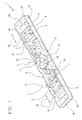
Figure 1 is a perspective view, with some parts removed in order to better illustrate others, of a preferred embodiment of an operating device for doors and windows according to this invention; -
Figure 2 is a perspective exploded view of the operating device ofFigure 1 ; -
Figures 3 and 4 are top plan views illustrating two different operating configurations of the operating device ofFigure 1 ; -
Figures 5 and 6 illustrate two details of the operating device ofFigure 1 ; and -
Figure 7 is a perspective view of the operating device for doors and windows ofFigure 1 installed on a door/window frame shown partly cut away. - With reference to the accompanying drawings, the
numeral 1 denotes in its entirety an operating device according to the invention for doors and windows with frames made of metal or the like and of PVC. - The
operating device 1 is advantageously applicable to windows known as "awning windows". Windows of this type (not fully illustrated in the drawings since they are of well-known type) comprise a sash that opens outwards from the bottom and is hinged at the top, along its upper rail, to a fixed window frame. - As shown in
Figure 7 , theoperating device 1 is connected to amobile frame 2 of a window sash. Themobile frame 2, as stated, comprises a metal or plastic profile, of which only a part is shown. - The window also comprises a fixed frame (not illustrated in the drawings) with which the
mobile frame 2 of the sash is associated. - The
operating device 1 is associated with alocking device 3 that is mobile between a locked configuration, where themobile frame 2 is engaged with the fixed frame, and an unlocked configuration, where themobile frame 2 is disengaged from the fixed frame. - The
locking device 3 may comprise one ormore rods 4 slidable in grooves made in themobile frame 2 and one or more locking elements fixed to the rod. In the window locked configuration, the locking elements, also referred to as "bosses" (not shown in the drawings) are stably accommodated in holes made in the fixed frame of the window. Thus, the sash cannot be moved away from the fixed frame and, hence, cannot be opened. In the unlocked configuration, the bosses are away from or outside the holes, thus enabling the sash to be moved away from the fixed frame and opened. - The
operating device 1 comprises at least onedrive member 5 functionally connected to thelocking device 3 for reversibly moving thelocking device 3 between the locked configuration and the unlocked configuration of the window. - The
drive member 5 is mobile along a direction "D1" parallel to the principal axis along which theoperating device 1 extends. In particular, the first direction "D1" is also parallel to a principal direction along which the portion of themobile frame 2 on which theoperating device 1 is mounted extends. - In the embodiment described, the
operating device 1 comprises a pair ofdrive members 5, each moving towards and/or away from the other. - The
operating device 1 also comprises control means 6 acting on eachdrive member 5 for reversibly switching thelocking device 3 between the locked and unlocked configurations of the window. - Each
drive member 5 comprises afastening element 7 necessary to stably connect thelocking device 3 to thedrive member 5 itself. - Each
fastening element 7 is mobile along a second direction "D2" perpendicular to the first direction "D1" between a first and a second end position (two example positions are shown inFigure 3 ). - More specifically, each
fastening element 7 is mobile in such a way that it can adopt a plurality of stable positions included between the first and the second end position, thus adapting to the position of the hole in therod 4. - Looking in more detail, each
drive member 5 also comprises arespective guide 8 slidable along the above mentioned first direction "D1" and where eachfastening element 7 is slidably inserted. More specifically, eachguide 8 slides between a first position (Figure 3 ), where theguides 8 are closer together, and a second position (Figure 4 ), where theguides 8 are further apart. - Each
fastening element 7 comprises aslider 9 that is slidably mounted in therespective guide 8 and is substantially in the shape of a parallelepiped. Theslider 9 has apin 10 located near afirst end 9a of theslider 9 itself. Thepin 10 is accommodated in ahole 11 made in therod 4 of thelocking device 3 so as to couple thelocking device 3 itself to eachdrive member 5. - The
slider 9 also has ashoulder 12 located near asecond end 9b of theslider 9, opposite thefirst end 9a along the principal direction in whichoperating device 1 extends. When the rod of thelocking device 3 is coupled to theslider 9, one end edge of therod 4 itself abuts against theshoulder 12. The coupling between therod 4 and theshoulder 12 minimizes any coupling problems between thepin 10 and thehole 11, thus reducing the play between them. - Each
guide 8 comprises abase wall 13 and twoopposite side walls 14. Theside walls 14 are parallel to each other and extend along the above mentioned second direction "D2". - Each
side wall 14 of theguide 8 has a respectivestraight groove 15 formed near thebase wall 13 of theguide 8 itself. - Each
fastening element 7 comprises twotabs 16 housed in thegrooves 15 in theguide 8 so as to render more stable the translational movement of thefastening element 7 along the second direction "D2". - In particular, the
tabs 16 are located near the above mentioned first andsecond ends slider 9. - The
operating device 1 comprises a case or containingelement 17 defining a slideway "V" for thedrive members 5. - More specifically, the containing
element 17 comprises abottom wall 18, a pair ofside walls 19 lying along the first direction "D1" and a pair ofend walls 20 lying along the second direction "D2". In other words, the containingelement 17 is substantially in the shape of a parallelepiped. - The
operating device 1 further comprises means 21 for accessing eachfastening element 7. - In the embodiment described, the access means 21 comprise at least one
slot 22 associated with arespective drive member 5. Eachslot 22 is made in thebottom wall 18 in the vicinity of arespective guide 8 when the latter is in the first and/or the second position. Theslot 22 provides access to the slideway "V". - The access means 21 also comprise an
opening 23 made in thebase wall 13 of eachguide 8. - Looking in more detail, when each
guide 8 is in the first and/or the second end position, theslots 22 made in thebottom wall 18 of the containingelement 17 are aligned with and placed over theopenings 23 in thebase walls 13 of theguides 8. Thus, eachfastening element 7 can be accessed from the outside of theoperating device 1 and moved along the second direction "D2". - To facilitate adjustment of each
fastening element 7 from the outside, thebottom surface 7a of eachfastening element 7 has aslit 24 made in it through which thefastening element 7 can be engaged and moved by a suitable tool. Looking in more detail, thebottom surface 7a of thefastening element 7 faces thebase wall 13 of therespective guide 8. - Each
drive member 5 also comprises arack 25 associated with eachguide 8 to allow eachguide 8 to move along the first direction "D1". Looking in more detail, eachrack 25 is made as a single part with theguide 8. - The
racks 25 are associated with the control means 6. More specifically, the control means 6 comprise apinion 26 that meshes with respectivetoothed portions 27 of theracks 25. - The
pinion 26 is located near a central zone of the containingelement 17 and its rotation axis "A" is perpendicular to the first and second directions "D1" and "D2". Thepinion 26 comprises atoothed crown 28 associated with a hollowcylindrical mounting element 29 having a square internal section. Thecylindrical element 29 has anextension 29a located at thebottom wall 18 of the containingelement 17. In particular, thebottom wall 18 of the containingelement 17 has ahole 30 that accommodates theextension 29a in such a way as to render more stable the rotational movement of thepinion 26. - The operating
device 1 also comprises alid 31, fixed with screws that are not illustrated, for at least partly covering the control means 6 and thedrive members 5. - The operating
device 1 is fixed to themobile frame 2 of the window using suitable first screws 32. The embodiment described comprises four first screws 32 (Figure 2 ) for fixing theoperating device 1 to themobile frame 2. - The
pinion 26 is coupled to ahandle 33 that can be operated by a user to switch theoperating device 1 between the locked and unlocked configurations (Figure 7 ). More specifically, thehandle 33 is coupled to thepinion 26 by asquare coupling pin 38, that is to say, a pin having a square cross section, that can be inserted into thehollow element 29 of thepinion 26. -
Figure 7 also shows ahandle 33 mountingelement 34 fixed to themobile frame 2 of the window by respectivesecond screws 35, and acap 36 for covering the mountingelement 34 of thehandle 33. Also shown are agrub screw 37 used to fasten thehandle 33 to thecoupling pin 38 and aseal 39 interposed between the handle and thecap 36 to prevent unwanted infiltration of water. - During installation, the operating
device 1 is fixed to themobile frame 2 of the window. Next, the operatingdevice 1 is coupled to thelocking device 3. More specifically, therods 4 of thelocking device 3 are inserted into the respective grooves in such a way that the holes made in the vicinity of their ends are positioned near eachfastening element 7. The installer acts on eachfastening element 7 through the above described access means 21 in such a way as to move thefastening elements 7 until thepin 10 on eachfastening element 7 is coaxially aligned with the hole in therespective rod 4. In this way, the operatingdevice 1 can be coupled to the locking device. - When a user turns the
handle 33, thepinion 26, integrally associated with thehandle 33, turns and causes theracks 25 to move in a straight line. The racks move theguides 8 of thedrive members 5 and, at the same time, thefastening elements 7. Thus, therods 4 of thelocking device 3 are moved in a straight line in such a way as to switch thelocking device 3 between the locked configuration and the unlocked configuration. - The invention achieves the above mentioned aims and brings important advantages.
- First of all, since the
fastening elements 7 used to couple theoperating device 1 to thelocking device 3 are mobile along the second direction "D2" perpendicular to the principal axis of theoperating device 1 itself, the operatingdevice 1 can be applied to many different types of profiles where the grooves that house therods 4 of thelocking device 3 are located in different positions. - That means the operating
device 1 can be adapted to suitrods 4 located in different positions and therefore having coupling holes 11 also located in different positions. - It is not therefore necessary to make
different operating devices 1 according to the type of profile used. This allows production costs to be significantly reduced. - Moreover, total warehouse space required to stock the
operating device 1 is also reduced, thus reducing warehousing requirements and costs accordingly. - The invention described above is susceptible of industrial application and may be modified and adapted in several ways without thereby departing from the scope of the inventive concept. Moreover, all details of the invention may be substituted by technically equivalent elements.
Claims (15)
- An operating device for doors and windows comprising:- at least one drive member (5) that can be associated with a locking device (3) to move the locking device (3) between a door/window locked configuration and a door/window unlocked configuration along a first direction (D1) parallel to the principal axis along which the operating device (1) extends;- control means (6) acting on the drive member (5) to switch the locking device (3) between the locked and unlocked configurations; the operating device being characterized in that the drive member (5) comprises a fastening element (7) to fix the locking device (3) to the drive member (5); the fastening element (7) being continuously mobile along a second direction (D2) perpendicular to the first direction (D1).
- The device according to claim 1, characterized in that the drive member (5) comprises a guide (8), extending along the direction (D2) and mobile as one with it along the first direction (D1); the fastening element (7) sliding freely in the guide (8).
- The device according to claim 1 or 2, characterized in that it further comprises means (21) for accessing the fastening element (7).
- The device according to claim 2 or 3, characterized in that the fastening element comprises a slider (7) that is slidably mounted in the guide (8) and a pin (10) protruding from the slider and designed to be accommodated in a hole made in the locking device (3).
- The device according to any of the claims from 2 to 4, characterized in that the guide (8) comprises a base wall (13) and two opposite side walls (14) extending along the second direction (D2); the guide (8) also having a groove (15) formed on each side wall (14).
- The device according to claim 5, characterized in that the fastening element (7) comprises at least one tab (16) housed in the groove (15) in the guide (8).
- The device according to any of the claims from 3 to 6, characterized in that it further comprises a containing elememt (17) defining a slideway (V) for the drive member (5); said containing element (17) comprising a bottom wall (18).
- The device according to claim 7, characterized in that the access means (21) comprise a slot (22) made in the bottom wall (18) of the containing element (17) to provide access to the slideway (V).
- The device according to claim 8, characterized in that the guide comprises a base wall (13) and in that the access means (21) further comprise an opening (23) made in the base wall (13) of the guide (8).
- The device according to claim 9, characterized in that the slot (22) in the bottom wall (18) of the containing element (17) can be placed over the opening (23) in the base wall (13) of the guide (8) to provide access to the fastening element (7) so as to move the latter along the second direction (D2).
- The device according to any of the claims from 3 to 10, characterized in that the fastening element (7) has a slit (24) made in a bottom surface (7a) of the slider (9) facing the base wall (13) of the guide (8); the slit (24) being accessible through the access means (21) to move the fastening element (7).
- The device according to any of the foregoing claims, characterized in that the drive member (5) further comprises a rack (25) associated with the guide (8).
- The device according to claim 12, characterized in that the guide (8) and the rack (25) are made as a single part.
- The device according to claim 12 or 13, characterized in that the control means (6) comprise a pinion (26) that meshes with the rack (25).
- The device according to any of the foregoing claims, characterized in that it comprises a pair of drive members (5), each mobile towards/away from the other.
Applications Claiming Priority (1)
| Application Number | Priority Date | Filing Date | Title |
|---|---|---|---|
| IT000499A ITBO20070499A1 (en) | 2007-07-19 | 2007-07-19 | FIXTURE MANEUVERING DEVICE. |
Publications (3)
| Publication Number | Publication Date |
|---|---|
| EP2017415A2 true EP2017415A2 (en) | 2009-01-21 |
| EP2017415A3 EP2017415A3 (en) | 2010-12-22 |
| EP2017415B1 EP2017415B1 (en) | 2011-10-12 |
Family
ID=39816702
Family Applications (1)
| Application Number | Title | Priority Date | Filing Date |
|---|---|---|---|
| EP08160316A Active EP2017415B1 (en) | 2007-07-19 | 2008-07-14 | An operating device for doors and windows |
Country Status (3)
| Country | Link |
|---|---|
| EP (1) | EP2017415B1 (en) |
| AT (1) | ATE528468T1 (en) |
| IT (1) | ITBO20070499A1 (en) |
Cited By (4)
| Publication number | Priority date | Publication date | Assignee | Title |
|---|---|---|---|---|
| EP2273045A1 (en) * | 2009-06-16 | 2011-01-12 | Ferco International Ferrures et Serrures de Bâtiment | Espagnolette lock for door, window or similar |
| WO2016020887A1 (en) * | 2014-08-08 | 2016-02-11 | Masterlab S.R.L. Unipersonale | Handle, in particular of the cremone bolt type, applicable onto the frame of a movable wing of a window or door |
| US20200224468A1 (en) * | 2019-01-11 | 2020-07-16 | Assa Abloy New Zealand Limited | Lock assembly |
| US20200291683A1 (en) * | 2017-11-02 | 2020-09-17 | Iloq Oy | Electromechanical lock utilizing magnetic field forces |
Citations (1)
| Publication number | Priority date | Publication date | Assignee | Title |
|---|---|---|---|---|
| FR2688821A1 (en) | 1992-03-20 | 1993-09-24 | Stremler | Lock, bolt or casement bolt with at least one locking point |
Family Cites Families (2)
| Publication number | Priority date | Publication date | Assignee | Title |
|---|---|---|---|---|
| FR2740502B1 (en) * | 1995-10-27 | 1998-01-02 | Vachette Sa | LOCK FOR OPERATION OF DOOR RODS |
| DE20301767U1 (en) * | 2003-02-05 | 2004-06-17 | Niederhoff & Dellenbusch Gmbh & Co | Actuating apparatus for door, has securement arms that extend from corresponding valve connection slide valves, and which are received in corresponding seats |
-
2007
- 2007-07-19 IT IT000499A patent/ITBO20070499A1/en unknown
-
2008
- 2008-07-14 EP EP08160316A patent/EP2017415B1/en active Active
- 2008-07-14 AT AT08160316T patent/ATE528468T1/en not_active IP Right Cessation
Patent Citations (1)
| Publication number | Priority date | Publication date | Assignee | Title |
|---|---|---|---|---|
| FR2688821A1 (en) | 1992-03-20 | 1993-09-24 | Stremler | Lock, bolt or casement bolt with at least one locking point |
Cited By (7)
| Publication number | Priority date | Publication date | Assignee | Title |
|---|---|---|---|---|
| EP2273045A1 (en) * | 2009-06-16 | 2011-01-12 | Ferco International Ferrures et Serrures de Bâtiment | Espagnolette lock for door, window or similar |
| WO2016020887A1 (en) * | 2014-08-08 | 2016-02-11 | Masterlab S.R.L. Unipersonale | Handle, in particular of the cremone bolt type, applicable onto the frame of a movable wing of a window or door |
| TWI666371B (en) * | 2014-08-08 | 2019-07-21 | 義大利商萬事實驗室私人有限公司 | Handle applicable onto the frame of a moveable wing of a window or door |
| US20200291683A1 (en) * | 2017-11-02 | 2020-09-17 | Iloq Oy | Electromechanical lock utilizing magnetic field forces |
| US11808057B2 (en) * | 2017-11-02 | 2023-11-07 | Iloq Oy | Electromechanical lock utilizing magnetic field forces |
| US20200224468A1 (en) * | 2019-01-11 | 2020-07-16 | Assa Abloy New Zealand Limited | Lock assembly |
| CN111434872A (en) * | 2019-01-11 | 2020-07-21 | 亚萨合莱新西兰有限公司 | Lock assembly |
Also Published As
| Publication number | Publication date |
|---|---|
| ITBO20070499A1 (en) | 2009-01-20 |
| ATE528468T1 (en) | 2011-10-15 |
| EP2017415A3 (en) | 2010-12-22 |
| EP2017415B1 (en) | 2011-10-12 |
Similar Documents
| Publication | Publication Date | Title |
|---|---|---|
| EP2220316B1 (en) | A carriage for sliding doors and windows | |
| US8413299B2 (en) | Hinge for door or window | |
| US7708322B2 (en) | Actuator for use in fenestration systems | |
| CN110573687A (en) | modular multipoint lock | |
| US9518411B2 (en) | Mortise door lock system | |
| EP3112570A1 (en) | Sliding-door closer set | |
| US7004515B2 (en) | Fenestration locking system | |
| KR101932938B1 (en) | Door structure having functions of sliding door and hinged door | |
| SK32794A3 (en) | Slide gear mechanism of windows or doors | |
| EP2017415B1 (en) | An operating device for doors and windows | |
| CA2911872A1 (en) | Around-the-corner multi-point lock mechanism for casement and awning windows | |
| US9160220B2 (en) | Linear actuator particularly for sliding doors and for sliding door or window closure elements in general | |
| GB2072740A (en) | Espagnolette fastening | |
| US4142747A (en) | Double-locking assembly for sliding glass closures | |
| WO2018140989A2 (en) | Shutters | |
| EP0742332A1 (en) | Operating mechanism for espagnolette fastening system | |
| KR101539772B1 (en) | Sliding door system | |
| EP2937496A1 (en) | Operating handle for a folding/sliding door | |
| EP1785562B1 (en) | Side-hung frame for doors and windows | |
| US20120139268A1 (en) | Locking device provided with at least one locking point for a sliding sash | |
| EP1536092B1 (en) | A corner transmission element for doors and windows | |
| AU2020204087A1 (en) | A sliding window or door lock | |
| CN102536008A (en) | Lock device and fitting | |
| EP2119859B1 (en) | Door and window bolt | |
| JP3183174U (en) | Electromechanical actuator head support device for driving movable home automation elements |
Legal Events
| Date | Code | Title | Description |
|---|---|---|---|
| PUAI | Public reference made under article 153(3) epc to a published international application that has entered the european phase |
Free format text: ORIGINAL CODE: 0009012 |
|
| AK | Designated contracting states |
Kind code of ref document: A2 Designated state(s): AT BE BG CH CY CZ DE DK EE ES FI FR GB GR HR HU IE IS IT LI LT LU LV MC MT NL NO PL PT RO SE SI SK TR |
|
| AX | Request for extension of the european patent |
Extension state: AL BA MK RS |
|
| PUAL | Search report despatched |
Free format text: ORIGINAL CODE: 0009013 |
|
| AK | Designated contracting states |
Kind code of ref document: A3 Designated state(s): AT BE BG CH CY CZ DE DK EE ES FI FR GB GR HR HU IE IS IT LI LT LU LV MC MT NL NO PL PT RO SE SI SK TR |
|
| AX | Request for extension of the european patent |
Extension state: AL BA MK RS |
|
| 17P | Request for examination filed |
Effective date: 20110228 |
|
| GRAP | Despatch of communication of intention to grant a patent |
Free format text: ORIGINAL CODE: EPIDOSNIGR1 |
|
| RIC1 | Information provided on ipc code assigned before grant |
Ipc: E05C 9/04 20060101ALI20110406BHEP Ipc: E05C 9/20 20060101AFI20110406BHEP |
|
| RIN1 | Information on inventor provided before grant (corrected) |
Inventor name: LAMBERTINI, MARCO |
|
| GRAS | Grant fee paid |
Free format text: ORIGINAL CODE: EPIDOSNIGR3 |
|
| AKX | Designation fees paid |
Designated state(s): AT BE BG CH CY CZ DE DK EE ES FI FR GB GR HR HU IE IS IT LI LT LU LV MC MT NL NO PL PT RO SE SI SK TR |
|
| GRAA | (expected) grant |
Free format text: ORIGINAL CODE: 0009210 |
|
| AK | Designated contracting states |
Kind code of ref document: B1 Designated state(s): AT BE BG CH CY CZ DE DK EE ES FI FR GB GR HR HU IE IS IT LI LT LU LV MC MT NL NO PL PT RO SE SI SK TR |
|
| REG | Reference to a national code |
Ref country code: GB Ref legal event code: FG4D |
|
| REG | Reference to a national code |
Ref country code: CH Ref legal event code: EP |
|
| REG | Reference to a national code |
Ref country code: IE Ref legal event code: FG4D |
|
| REG | Reference to a national code |
Ref country code: DE Ref legal event code: R096 Ref document number: 602008010344 Country of ref document: DE Effective date: 20120112 |
|
| REG | Reference to a national code |
Ref country code: NL Ref legal event code: VDEP Effective date: 20111012 |
|
| LTIE | Lt: invalidation of european patent or patent extension |
Effective date: 20111012 |
|
| REG | Reference to a national code |
Ref country code: AT Ref legal event code: MK05 Ref document number: 528468 Country of ref document: AT Kind code of ref document: T Effective date: 20111012 |
|
| PG25 | Lapsed in a contracting state [announced via postgrant information from national office to epo] |
Ref country code: IS Free format text: LAPSE BECAUSE OF FAILURE TO SUBMIT A TRANSLATION OF THE DESCRIPTION OR TO PAY THE FEE WITHIN THE PRESCRIBED TIME-LIMIT Effective date: 20120212 Ref country code: LT Free format text: LAPSE BECAUSE OF FAILURE TO SUBMIT A TRANSLATION OF THE DESCRIPTION OR TO PAY THE FEE WITHIN THE PRESCRIBED TIME-LIMIT Effective date: 20111012 Ref country code: NO Free format text: LAPSE BECAUSE OF FAILURE TO SUBMIT A TRANSLATION OF THE DESCRIPTION OR TO PAY THE FEE WITHIN THE PRESCRIBED TIME-LIMIT Effective date: 20120112 Ref country code: BE Free format text: LAPSE BECAUSE OF FAILURE TO SUBMIT A TRANSLATION OF THE DESCRIPTION OR TO PAY THE FEE WITHIN THE PRESCRIBED TIME-LIMIT Effective date: 20111012 |
|
| PG25 | Lapsed in a contracting state [announced via postgrant information from national office to epo] |
Ref country code: SI Free format text: LAPSE BECAUSE OF FAILURE TO SUBMIT A TRANSLATION OF THE DESCRIPTION OR TO PAY THE FEE WITHIN THE PRESCRIBED TIME-LIMIT Effective date: 20111012 Ref country code: NL Free format text: LAPSE BECAUSE OF FAILURE TO SUBMIT A TRANSLATION OF THE DESCRIPTION OR TO PAY THE FEE WITHIN THE PRESCRIBED TIME-LIMIT Effective date: 20111012 Ref country code: HR Free format text: LAPSE BECAUSE OF FAILURE TO SUBMIT A TRANSLATION OF THE DESCRIPTION OR TO PAY THE FEE WITHIN THE PRESCRIBED TIME-LIMIT Effective date: 20111012 Ref country code: SE Free format text: LAPSE BECAUSE OF FAILURE TO SUBMIT A TRANSLATION OF THE DESCRIPTION OR TO PAY THE FEE WITHIN THE PRESCRIBED TIME-LIMIT Effective date: 20111012 Ref country code: GR Free format text: LAPSE BECAUSE OF FAILURE TO SUBMIT A TRANSLATION OF THE DESCRIPTION OR TO PAY THE FEE WITHIN THE PRESCRIBED TIME-LIMIT Effective date: 20120113 Ref country code: PT Free format text: LAPSE BECAUSE OF FAILURE TO SUBMIT A TRANSLATION OF THE DESCRIPTION OR TO PAY THE FEE WITHIN THE PRESCRIBED TIME-LIMIT Effective date: 20120213 Ref country code: LV Free format text: LAPSE BECAUSE OF FAILURE TO SUBMIT A TRANSLATION OF THE DESCRIPTION OR TO PAY THE FEE WITHIN THE PRESCRIBED TIME-LIMIT Effective date: 20111012 |
|
| PG25 | Lapsed in a contracting state [announced via postgrant information from national office to epo] |
Ref country code: CY Free format text: LAPSE BECAUSE OF FAILURE TO SUBMIT A TRANSLATION OF THE DESCRIPTION OR TO PAY THE FEE WITHIN THE PRESCRIBED TIME-LIMIT Effective date: 20111012 |
|
| PG25 | Lapsed in a contracting state [announced via postgrant information from national office to epo] |
Ref country code: EE Free format text: LAPSE BECAUSE OF FAILURE TO SUBMIT A TRANSLATION OF THE DESCRIPTION OR TO PAY THE FEE WITHIN THE PRESCRIBED TIME-LIMIT Effective date: 20111012 Ref country code: SK Free format text: LAPSE BECAUSE OF FAILURE TO SUBMIT A TRANSLATION OF THE DESCRIPTION OR TO PAY THE FEE WITHIN THE PRESCRIBED TIME-LIMIT Effective date: 20111012 Ref country code: DK Free format text: LAPSE BECAUSE OF FAILURE TO SUBMIT A TRANSLATION OF THE DESCRIPTION OR TO PAY THE FEE WITHIN THE PRESCRIBED TIME-LIMIT Effective date: 20111012 Ref country code: BG Free format text: LAPSE BECAUSE OF FAILURE TO SUBMIT A TRANSLATION OF THE DESCRIPTION OR TO PAY THE FEE WITHIN THE PRESCRIBED TIME-LIMIT Effective date: 20120112 Ref country code: CZ Free format text: LAPSE BECAUSE OF FAILURE TO SUBMIT A TRANSLATION OF THE DESCRIPTION OR TO PAY THE FEE WITHIN THE PRESCRIBED TIME-LIMIT Effective date: 20111012 |
|
| PLBE | No opposition filed within time limit |
Free format text: ORIGINAL CODE: 0009261 |
|
| STAA | Information on the status of an ep patent application or granted ep patent |
Free format text: STATUS: NO OPPOSITION FILED WITHIN TIME LIMIT |
|
| PG25 | Lapsed in a contracting state [announced via postgrant information from national office to epo] |
Ref country code: RO Free format text: LAPSE BECAUSE OF FAILURE TO SUBMIT A TRANSLATION OF THE DESCRIPTION OR TO PAY THE FEE WITHIN THE PRESCRIBED TIME-LIMIT Effective date: 20111012 Ref country code: PL Free format text: LAPSE BECAUSE OF FAILURE TO SUBMIT A TRANSLATION OF THE DESCRIPTION OR TO PAY THE FEE WITHIN THE PRESCRIBED TIME-LIMIT Effective date: 20111012 |
|
| 26N | No opposition filed |
Effective date: 20120713 |
|
| REG | Reference to a national code |
Ref country code: DE Ref legal event code: R097 Ref document number: 602008010344 Country of ref document: DE Effective date: 20120713 |
|
| PG25 | Lapsed in a contracting state [announced via postgrant information from national office to epo] |
Ref country code: AT Free format text: LAPSE BECAUSE OF FAILURE TO SUBMIT A TRANSLATION OF THE DESCRIPTION OR TO PAY THE FEE WITHIN THE PRESCRIBED TIME-LIMIT Effective date: 20111012 |
|
| PG25 | Lapsed in a contracting state [announced via postgrant information from national office to epo] |
Ref country code: MC Free format text: LAPSE BECAUSE OF NON-PAYMENT OF DUE FEES Effective date: 20120731 |
|
| REG | Reference to a national code |
Ref country code: CH Ref legal event code: PL |
|
| REG | Reference to a national code |
Ref country code: FR Ref legal event code: ST Effective date: 20130329 |
|
| PG25 | Lapsed in a contracting state [announced via postgrant information from national office to epo] |
Ref country code: LI Free format text: LAPSE BECAUSE OF NON-PAYMENT OF DUE FEES Effective date: 20120731 Ref country code: FR Free format text: LAPSE BECAUSE OF NON-PAYMENT OF DUE FEES Effective date: 20120731 Ref country code: CH Free format text: LAPSE BECAUSE OF NON-PAYMENT OF DUE FEES Effective date: 20120731 |
|
| REG | Reference to a national code |
Ref country code: IE Ref legal event code: MM4A |
|
| PG25 | Lapsed in a contracting state [announced via postgrant information from national office to epo] |
Ref country code: FI Free format text: LAPSE BECAUSE OF FAILURE TO SUBMIT A TRANSLATION OF THE DESCRIPTION OR TO PAY THE FEE WITHIN THE PRESCRIBED TIME-LIMIT Effective date: 20111012 |
|
| PG25 | Lapsed in a contracting state [announced via postgrant information from national office to epo] |
Ref country code: IE Free format text: LAPSE BECAUSE OF NON-PAYMENT OF DUE FEES Effective date: 20120714 Ref country code: MT Free format text: LAPSE BECAUSE OF FAILURE TO SUBMIT A TRANSLATION OF THE DESCRIPTION OR TO PAY THE FEE WITHIN THE PRESCRIBED TIME-LIMIT Effective date: 20111012 |
|
| PG25 | Lapsed in a contracting state [announced via postgrant information from national office to epo] |
Ref country code: ES Free format text: LAPSE BECAUSE OF FAILURE TO SUBMIT A TRANSLATION OF THE DESCRIPTION OR TO PAY THE FEE WITHIN THE PRESCRIBED TIME-LIMIT Effective date: 20120123 |
|
| PG25 | Lapsed in a contracting state [announced via postgrant information from national office to epo] |
Ref country code: TR Free format text: LAPSE BECAUSE OF FAILURE TO SUBMIT A TRANSLATION OF THE DESCRIPTION OR TO PAY THE FEE WITHIN THE PRESCRIBED TIME-LIMIT Effective date: 20111012 |
|
| PG25 | Lapsed in a contracting state [announced via postgrant information from national office to epo] |
Ref country code: LU Free format text: LAPSE BECAUSE OF NON-PAYMENT OF DUE FEES Effective date: 20120714 |
|
| PG25 | Lapsed in a contracting state [announced via postgrant information from national office to epo] |
Ref country code: HU Free format text: LAPSE BECAUSE OF FAILURE TO SUBMIT A TRANSLATION OF THE DESCRIPTION OR TO PAY THE FEE WITHIN THE PRESCRIBED TIME-LIMIT Effective date: 20080714 |
|
| PGFP | Annual fee paid to national office [announced via postgrant information from national office to epo] |
Ref country code: PL Payment date: 20170620 Year of fee payment: 6 |
|
| GBPC | Gb: european patent ceased through non-payment of renewal fee |
Effective date: 20180714 |
|
| PG25 | Lapsed in a contracting state [announced via postgrant information from national office to epo] |
Ref country code: GB Free format text: LAPSE BECAUSE OF NON-PAYMENT OF DUE FEES Effective date: 20180714 |
|
| P01 | Opt-out of the competence of the unified patent court (upc) registered |
Effective date: 20230506 |
|
| PGFP | Annual fee paid to national office [announced via postgrant information from national office to epo] |
Ref country code: IT Payment date: 20230720 Year of fee payment: 16 |
|
| PGFP | Annual fee paid to national office [announced via postgrant information from national office to epo] |
Ref country code: DE Payment date: 20230726 Year of fee payment: 16 |