EP2016988A1 - Metallurgical granulation and dewatering apparatus - Google Patents
Metallurgical granulation and dewatering apparatus Download PDFInfo
- Publication number
- EP2016988A1 EP2016988A1 EP07112769A EP07112769A EP2016988A1 EP 2016988 A1 EP2016988 A1 EP 2016988A1 EP 07112769 A EP07112769 A EP 07112769A EP 07112769 A EP07112769 A EP 07112769A EP 2016988 A1 EP2016988 A1 EP 2016988A1
- Authority
- EP
- European Patent Office
- Prior art keywords
- drum
- mesh material
- mesh
- slag
- nozzles
- Prior art date
- Legal status (The legal status is an assumption and is not a legal conclusion. Google has not performed a legal analysis and makes no representation as to the accuracy of the status listed.)
- Withdrawn
Links
- 230000003179 granulation Effects 0.000 title claims abstract description 14
- 238000005469 granulation Methods 0.000 title claims abstract description 14
- 239000000463 material Substances 0.000 claims abstract description 66
- XLYOFNOQVPJJNP-UHFFFAOYSA-N water Substances O XLYOFNOQVPJJNP-UHFFFAOYSA-N 0.000 claims abstract description 50
- 239000002893 slag Substances 0.000 claims abstract description 45
- 239000002002 slurry Substances 0.000 claims abstract description 28
- 238000004140 cleaning Methods 0.000 claims abstract description 17
- 239000002184 metal Substances 0.000 description 8
- 230000002093 peripheral effect Effects 0.000 description 3
- 230000004323 axial length Effects 0.000 description 2
- 239000011148 porous material Substances 0.000 description 2
- 238000003723 Smelting Methods 0.000 description 1
- 239000006227 byproduct Substances 0.000 description 1
- 230000000694 effects Effects 0.000 description 1
- 239000012530 fluid Substances 0.000 description 1
- 239000008187 granular material Substances 0.000 description 1
- 230000003993 interaction Effects 0.000 description 1
- 238000012423 maintenance Methods 0.000 description 1
- 239000000203 mixture Substances 0.000 description 1
- 239000007787 solid Substances 0.000 description 1
- 239000007921 spray Substances 0.000 description 1
Images
Classifications
-
- B—PERFORMING OPERATIONS; TRANSPORTING
- B01—PHYSICAL OR CHEMICAL PROCESSES OR APPARATUS IN GENERAL
- B01D—SEPARATION
- B01D33/00—Filters with filtering elements which move during the filtering operation
- B01D33/06—Filters with filtering elements which move during the filtering operation with rotary cylindrical filtering surfaces, e.g. hollow drums
- B01D33/11—Filters with filtering elements which move during the filtering operation with rotary cylindrical filtering surfaces, e.g. hollow drums arranged for outward flow filtration
-
- B—PERFORMING OPERATIONS; TRANSPORTING
- B01—PHYSICAL OR CHEMICAL PROCESSES OR APPARATUS IN GENERAL
- B01D—SEPARATION
- B01D33/00—Filters with filtering elements which move during the filtering operation
- B01D33/44—Regenerating the filter material in the filter
- B01D33/48—Regenerating the filter material in the filter by flushing, e.g. counter-current air-bumps
- B01D33/50—Regenerating the filter material in the filter by flushing, e.g. counter-current air-bumps with backwash arms, shoes or nozzles
-
- B—PERFORMING OPERATIONS; TRANSPORTING
- B01—PHYSICAL OR CHEMICAL PROCESSES OR APPARATUS IN GENERAL
- B01D—SEPARATION
- B01D33/00—Filters with filtering elements which move during the filtering operation
- B01D33/44—Regenerating the filter material in the filter
- B01D33/52—Regenerating the filter material in the filter by forces created by movement of the filter element
-
- C—CHEMISTRY; METALLURGY
- C21—METALLURGY OF IRON
- C21B—MANUFACTURE OF IRON OR STEEL
- C21B2400/00—Treatment of slags originating from iron or steel processes
- C21B2400/02—Physical or chemical treatment of slags
- C21B2400/022—Methods of cooling or quenching molten slag
- C21B2400/024—Methods of cooling or quenching molten slag with the direct use of steam or liquid coolants, e.g. water
-
- C—CHEMISTRY; METALLURGY
- C21—METALLURGY OF IRON
- C21B—MANUFACTURE OF IRON OR STEEL
- C21B2400/00—Treatment of slags originating from iron or steel processes
- C21B2400/02—Physical or chemical treatment of slags
- C21B2400/032—Separating slag from liquid, e.g. from water, after quenching
-
- C—CHEMISTRY; METALLURGY
- C21—METALLURGY OF IRON
- C21B—MANUFACTURE OF IRON OR STEEL
- C21B2400/00—Treatment of slags originating from iron or steel processes
- C21B2400/05—Apparatus features
- C21B2400/052—Apparatus features including rotating parts
-
- C—CHEMISTRY; METALLURGY
- C21—METALLURGY OF IRON
- C21B—MANUFACTURE OF IRON OR STEEL
- C21B2400/00—Treatment of slags originating from iron or steel processes
- C21B2400/05—Apparatus features
- C21B2400/052—Apparatus features including rotating parts
- C21B2400/056—Drums whereby slag is poured on or in between
Definitions
- the present invention generally relates to a metallurgical granulation and dewatering apparatus, in particular for granulating molten slag from a blast furnace and for removing water from the granulated slag. The granulated slag is then recovered and transported away for use elsewhere.
- Slag such as produced by a blast furnace
- the molten slag is generally mixed with water, which serves to cool down the molten slag and to break it up into granules. From the mixture of water and slag, generally called slurry, it is necessary to separate the water from the granulated slag, so that the latter can be stored, transported and used.
- a metallurgical granulation and dewatering apparatus is e.g. known from US 4,204,855 .
- Such a granulation and dewatering apparatus comprises a hollow rotary drum, rotatably mounted about a central axis.
- the drum wall is formed in a foraminous material, allowing water to drain away.
- the apparatus is provided with means for feeding slag into a lower region of the hollow drum and onto the inner surface of the drum wall.
- the slurry containing the slag is entrained from the lower region of the drum towards an upper region of the drum, while water is drained away.
- the dewatered granulated slag is allowed to fall under gravitational force onto a conveyor for catching the granulated slag and conveying it out of the hollow drum.
- the object of the present invention is to provide an improved metallurgical granulation and dewatering apparatus, wherein cleaning of the drum walls is improved. This object is achieved by an apparatus as claimed in claim 1.
- the present invention proposes a metallurgical granulation and dewatering apparatus, in particular for recovering granulated slag from a blast furnace, the metallurgical granulation and dewatering apparatus comprising a hollow drum being rotatably mounted about an axis, the drum being formed by a drum wall comprising mesh material.
- the apparatus further comprises feed means for feeding granulated slag into a lower region of the drum and onto an inner surface of the drum wall, the lower region of the drum comprising a slag/water slurry; and drive means for rotating the drum about the axis, the rotation of the drum causing the slurry to be entrained from the lower region of the drum to an upper region of the drum, the water being drained away through the mesh material.
- the apparatus also comprises collector means arranged in the drum at a location below the upper region of the drum, the collector means being arranged for catching slag and conveying the slag out of the drum; and cleaning means for cleaning the mesh material, the cleaning means being arranged outside the drum and comprising nozzles directed onto the outer surface of the mesh material.
- the mesh material is flexible mesh material and the nozzles of the cleaning means are high-pressure water nozzles for directing high-pressure water jets onto the outer surface of the flexible mesh material; wherein the flexible mesh material is configured and arranged so as to be able to bulge inwardly when subjected to water from the high-pressure water nozzles.
- the apparatus further comprises a plurality of inwardly projecting vanes on the inner surface of the drum wall, the vanes being configured and arranged so as to entrain the slurry towards the upper region of the drum upon rotation of the drum.
- vanes improve the entrainment of the slurry towards the upper region of the drum, thereby increasing the efficiency of the apparatus.
- the vanes at least partially have a mesh structure, thereby facilitating the removal of water from the entrained slurry.
- the high-pressure water nozzles are configured and arranged so as to direct high-pressure water jets onto the drum at a location downstream of where the slag falls onto the collector means. After the granulated slag is dropped from a particular area of the mesh material onto the collector means, that area passes in front of the high-pressure water nozzles before it reaches the lower region of the drum to pick up more slurry.
- the high-pressure water nozzles are preferably configured and arranged so as to produce water jets at a pressure higher than 40 bar, preferably higher than 50 bar.
- the hollow drum comprises a support structure having a frame for receiving the mesh material thereon.
- the frame may be a regular grid of peripheral and longitudinal metal bars defining the wall of the hollow drum, wherein the metal bars are arranged in such a way as to receive the mesh material.
- the support structure may further comprise rigid support material having a mesh structure, the flexible mesh material being arranged along the inside surface of the rigid support material.
- rigid support material e.g. in the form of support panels, allow to reinforce the support structure and hence the hollow drum.
- the support material also allows preventing the flexible mesh material from falling out of the hollow drum.
- the rigid support material preferably has a mesh size that is substantially bigger than the mesh size of the flexible mesh material.
- the mesh material is sandwiched between the support material and the support structure.
- the flexible mesh material is thereby rigidly connected, at its intersections with the frame of the support structure, with the support structure and only central portions of the mesh material remain flexible. This does not only allow the flexible mesh material to stay in place, it also allows creating smaller bulging zones.
- the flexible mesh material is removably attached to the support structure. If need be, the flexible mesh material can then be removed and replaced easily and quickly.
- the mesh material is provided in the form of a plurality of mesh panels.
- Such mesh panels are preferably dimensioned so as to have their edges in contact with the frame of the support structure.
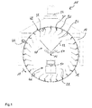
- Fig.1 shows a metallurgical granulation and dewatering apparatus 10 according to the invention, wherein a hollow drum 12 is arranged inside a chamber 14.
- the drum is arranged so as to be rotatable about a central axis 16 and is coupled to a motor (not shown) for rotating the drum 12 in a direction as indicated by arrow 18.
- Such a drum 12 typically comprises a drum wall 20 formed in a foraminous material, allowing water to drain away.
- the drum 12 generally has a lower region 22 comprising a slag/water slurry and an upper region 24 where slag material entrained by the rotating drum 12 falls away from the drum wall 20.
- a drum 12 comprises a support structure with a frame constructed from a plurality of peripheral and longitudinal metal bars for defining the drum wall 30.
- Rigid support panels having a mesh structure are arranged in the spaces defined between the peripheral and longitudinal metal bars. Together with the frame, the support panels form a solid drum wall.
- the drum wall further comprises an inner lining of mesh material in the form of mesh panels.
- the mesh panels have relatively small mesh size, whereas the support panels have substantially larger mesh size.
- Such mesh panels are designed to carry the slag/water slurry and to allow the water to drain away from the slurry through the mesh panels while still carrying the granulated slag.
- a plurality of inwardly projecting vanes 30 is arranged on the inner surface 32 of the drum wall 20. These vanes 30 are configured and arranged so as to, upon rotation of the drum 12, entrain the slurry from the lower region 22 towards the upper region 24 of the drum 12.
- the vanes 30 preferably also have a mesh structure in order to allow water to drain away from the entrained slurry.
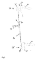
- Fig.2 shows an enlarged cross-sectional view of a section of drum wall 20.
- This figure shows two neighbouring longitudinal metal bars 34, 34' and a rigid support panel 36 arranged therebetween.
- Each longitudinal metal bar 34, 34' comprises an outer part 38, 38' and an inner part 40, 40', edge portions of the support panel 36 being sandwiched therebetween.
- the inner part 40, 40' may also carry the vanes 30 thereon.
- the rigid support panel 36 is internally lined with a mesh panel 41, which has its edge portions sandwiched between the rigid support panel 36 and the inner part 40, 40' of the metal bars 34, 34'.
- the mesh panel 41 is a flexible mesh panel, which, when subjected to a jet of water at high pressure bulges inwardly as seen on Fig.2 . This bulging of the flexible mesh panel 41 ensures that any slag or slurry on the mesh panel 41 is removed before the mesh panel 41 returns to the lower region 22 of the drum 12 to entrain more slurry. As a consequence, the mesh panels 41 are continuously cleaned and their pores are prevented from clogging. The mesh panels 41 hence have a longer lifetime and maintenance stoppages, in order to replace or clean mesh panels 41, can be reduced.
- the jet of water at high pressure is delivered to the outside surface 42 of the drum 12 by means of a high-pressure water nozzle 44.
- a plurality of such nozzles 44 is arranged in a longitudinal array, laterally of the hollow drum 12 on the side of the drum 12 where the panels 36, 41 move in a downward direction as can be seen by referring back to Fig.1 .
- the nozzles 44 are arranged between the upper region 24 where slag material entrained by the rotating drum 12 falls away from the drum wall 20 and the lower region 22 comprising the slag/water slurry.
- the apparatus 10 further comprises feed means 46 for feeding molten slag into the drum 12 and collector means 48 for removing granulated slag from the drum 12.
- the feed means 46 e.g. comprises a pouring trough 50, which may be tilted to feed molten slag into the lower region 22 of the hollow drum 12, uniformly over substantially the entire axial length of the drum 12.
- the collector means 48 is arranged above the feed means 46 and extends over substantially the entire axial length of the drum 12.
- It comprises a funnel 52 for collecting the granulated slag falling off the drum wall 20 in the upper region 24 of the drum 12 , the funnel 52 feeding the granulated slag onto a collector plate 54 for carrying the collected granulated slag out of the hollow drum 12.
- the apparatus 10 further comprises an exhaust hood 56 for collecting any vapours from the metallurgical granulation and dewatering apparatus and a collecting basin (not shown) under the drum 12 for collecting and evacuating the water drained from the slurry.
- the slag containing slurry Upon rotation of the drum, the slag containing slurry is entrained by the drum wall 20 and the vanes 30 attached thereto from the lower region 22 of the drum 12 towards the upper region 24 of the drum 12, while water is drained away.
- the dewatered granulated slag In the upper region of the drum 12, the dewatered granulated slag is allowed to fall under gravitational force into the funnel 52 and onto the collector plate 54 for catching the dewatered granulated slag and conveying it out of the hollow drum 12.
Landscapes
- Chemical & Material Sciences (AREA)
- Chemical Kinetics & Catalysis (AREA)
- Manufacture And Refinement Of Metals (AREA)
- Disintegrating Or Milling (AREA)
Abstract
The present invention proposes a metallurgical granulation and dewatering apparatus (10) comprising a hollow drum (12) being rotatably mounted about an axis (16), the drum (12) being formed by a drum wall (20) comprising mesh material (41). The apparatus (10) further comprises feed means (46) for feeding granulated slag into a lower region (22) of the drum (12) and onto an inner surface (32) of the drum wall (20), the lower region (22) of the drum (12) comprising a slag/water slurry; and drive means for rotating the drum (12) about the axis (16), the rotation of the drum (12) causing the slurry to be entrained from the lower region (22) of the drum (12) to an upper region (24) of the drum (12), the water being drained away through the mesh material (41). The apparatus (10) also comprises collector means (48) arranged in the drum (12) at a location below the upper region (24) of the drum (12), the collector means (48) being arranged for catching slag and conveying the slag out of the drum (12); and cleaning means for cleaning the mesh material (41), the cleaning means being arranged outside the drum (12) and comprising nozzles (44) directed onto the outer surface (42) of the mesh material (41). According to an important aspect of the invention, the mesh material (41) is flexible mesh material and the nozzles (44) of the cleaning means are high-pressure water nozzles (44) for directing high-pressure water jets onto the outer surface (42) of the flexible mesh material (41); wherein the flexible mesh material (41) is configured and arranged so as to be able to bulge inwardly when subjected to water from the high-pressure water nozzles (44).
Description
- The present invention generally relates to a metallurgical granulation and dewatering apparatus, in particular for granulating molten slag from a blast furnace and for removing water from the granulated slag. The granulated slag is then recovered and transported away for use elsewhere.
- Slag, such as produced by a blast furnace, is a valuable byproduct of the smelting operation. The molten slag is generally mixed with water, which serves to cool down the molten slag and to break it up into granules. From the mixture of water and slag, generally called slurry, it is necessary to separate the water from the granulated slag, so that the latter can be stored, transported and used.
- A metallurgical granulation and dewatering apparatus is e.g. known from
US 4,204,855 . Such a granulation and dewatering apparatus comprises a hollow rotary drum, rotatably mounted about a central axis. The drum wall is formed in a foraminous material, allowing water to drain away. The apparatus is provided with means for feeding slag into a lower region of the hollow drum and onto the inner surface of the drum wall. Upon rotation of the drum, the slurry containing the slag is entrained from the lower region of the drum towards an upper region of the drum, while water is drained away. In the upper region of the drum, the dewatered granulated slag is allowed to fall under gravitational force onto a conveyor for catching the granulated slag and conveying it out of the hollow drum. - One problem encountered with such an apparatus is that the slurry entrained by the drum may stick on the inner surface of the drum wall and in particular in the openings of the foraminous material. It has therefore been suggested to spray a fluid, generally air at about 5 to 6 bar or water at about 7 to 10 bar, onto the outside surface of the hollow drum in order to remove the slurry from the drum wall before it reaches the lower region of the drum to pick up more slurry.
- Although such cleaning systems may help to reduce the build-up of slurry on the inner wall of the hollow drum, it has been found that the cleaning effect of these systems is insufficient and clogging of the pores of the foraminous material is not prevented.
- The object of the present invention is to provide an improved metallurgical granulation and dewatering apparatus, wherein cleaning of the drum walls is improved. This object is achieved by an apparatus as claimed in claim 1.
- The present invention proposes a metallurgical granulation and dewatering apparatus, in particular for recovering granulated slag from a blast furnace, the metallurgical granulation and dewatering apparatus comprising a hollow drum being rotatably mounted about an axis, the drum being formed by a drum wall comprising mesh material. The apparatus further comprises feed means for feeding granulated slag into a lower region of the drum and onto an inner surface of the drum wall, the lower region of the drum comprising a slag/water slurry; and drive means for rotating the drum about the axis, the rotation of the drum causing the slurry to be entrained from the lower region of the drum to an upper region of the drum, the water being drained away through the mesh material. The apparatus also comprises collector means arranged in the drum at a location below the upper region of the drum, the collector means being arranged for catching slag and conveying the slag out of the drum; and cleaning means for cleaning the mesh material, the cleaning means being arranged outside the drum and comprising nozzles directed onto the outer surface of the mesh material. According to an important aspect of the invention, the mesh material is flexible mesh material and the nozzles of the cleaning means are high-pressure water nozzles for directing high-pressure water jets onto the outer surface of the flexible mesh material; wherein the flexible mesh material is configured and arranged so as to be able to bulge inwardly when subjected to water from the high-pressure water nozzles.
- It has been found that the interaction between flexible mesh material and high-pressure water jets provides a very efficient cleaning of the mesh material. Indeed, as the flexible mesh material passes in the path of the high-pressure water jets, the mesh material bulges radially inwards. The movement of the mesh structure, together with the high-pressure water jet, provides an increased loosening of any slurry on the mesh material and thereby leads to an improved cleaning of the mesh material.
- According to a preferred embodiment of the invention, the apparatus further comprises a plurality of inwardly projecting vanes on the inner surface of the drum wall, the vanes being configured and arranged so as to entrain the slurry towards the upper region of the drum upon rotation of the drum. Such vanes improve the entrainment of the slurry towards the upper region of the drum, thereby increasing the efficiency of the apparatus. Preferably, the vanes at least partially have a mesh structure, thereby facilitating the removal of water from the entrained slurry.
- Advantageously, the high-pressure water nozzles are configured and arranged so as to direct high-pressure water jets onto the drum at a location downstream of where the slag falls onto the collector means. After the granulated slag is dropped from a particular area of the mesh material onto the collector means, that area passes in front of the high-pressure water nozzles before it reaches the lower region of the drum to pick up more slurry. The high-pressure water nozzles are preferably configured and arranged so as to produce water jets at a pressure higher than 40 bar, preferably higher than 50 bar.
- Preferably, the hollow drum comprises a support structure having a frame for receiving the mesh material thereon. The frame may be a regular grid of peripheral and longitudinal metal bars defining the wall of the hollow drum, wherein the metal bars are arranged in such a way as to receive the mesh material.
- The support structure may further comprise rigid support material having a mesh structure, the flexible mesh material being arranged along the inside surface of the rigid support material. Such rigid support material, e.g. in the form of support panels, allow to reinforce the support structure and hence the hollow drum. The support material also allows preventing the flexible mesh material from falling out of the hollow drum.
- The rigid support material preferably has a mesh size that is substantially bigger than the mesh size of the flexible mesh material.
- Advantageously, the mesh material is sandwiched between the support material and the support structure. The flexible mesh material is thereby rigidly connected, at its intersections with the frame of the support structure, with the support structure and only central portions of the mesh material remain flexible. This does not only allow the flexible mesh material to stay in place, it also allows creating smaller bulging zones.
- Preferably, the flexible mesh material is removably attached to the support structure. If need be, the flexible mesh material can then be removed and replaced easily and quickly.
- According to a particularly advantageous embodiment, the mesh material is provided in the form of a plurality of mesh panels. Such mesh panels are preferably dimensioned so as to have their edges in contact with the frame of the support structure.
- The present invention will be more apparent from the following description of a non-limiting embodiment with reference to the attached drawings, wherein:
-
FIG. 1 : is a schematic representation of a metallurgical granulation and dewatering apparatus according to the present invention; and -
FIG. 2 : is an enlarged cross-sectional view of a section of the drum wall of the apparatus ofFig.1 . -
Fig.1 shows a metallurgical granulation and dewateringapparatus 10 according to the invention, wherein a hollow drum 12 is arranged inside achamber 14. The drum is arranged so as to be rotatable about acentral axis 16 and is coupled to a motor (not shown) for rotating the drum 12 in a direction as indicated byarrow 18. - Such a drum 12 typically comprises a
drum wall 20 formed in a foraminous material, allowing water to drain away. The drum 12 generally has alower region 22 comprising a slag/water slurry and anupper region 24 where slag material entrained by the rotating drum 12 falls away from thedrum wall 20. - A drum 12, according to a preferred embodiment of the invention, comprises a support structure with a frame constructed from a plurality of peripheral and longitudinal metal bars for defining the
drum wall 30. Rigid support panels having a mesh structure are arranged in the spaces defined between the peripheral and longitudinal metal bars. Together with the frame, the support panels form a solid drum wall. The drum wall further comprises an inner lining of mesh material in the form of mesh panels. The mesh panels have relatively small mesh size, whereas the support panels have substantially larger mesh size. Such mesh panels are designed to carry the slag/water slurry and to allow the water to drain away from the slurry through the mesh panels while still carrying the granulated slag. - A plurality of inwardly projecting
vanes 30 is arranged on theinner surface 32 of thedrum wall 20. Thesevanes 30 are configured and arranged so as to, upon rotation of the drum 12, entrain the slurry from thelower region 22 towards theupper region 24 of the drum 12. Thevanes 30 preferably also have a mesh structure in order to allow water to drain away from the entrained slurry. - The structure of the
drum wall 20 can be more closely described by referring toFig.2 , which shows an enlarged cross-sectional view of a section ofdrum wall 20. This figure shows two neighbouring longitudinal metal bars 34, 34' and arigid support panel 36 arranged therebetween. Eachlongitudinal metal bar 34, 34' comprises anouter part 38, 38' and aninner part 40, 40', edge portions of thesupport panel 36 being sandwiched therebetween. Theinner part 40, 40' may also carry thevanes 30 thereon. - The
rigid support panel 36 is internally lined with a mesh panel 41, which has its edge portions sandwiched between therigid support panel 36 and theinner part 40, 40' of the metal bars 34, 34'. According to the present invention, the mesh panel 41 is a flexible mesh panel, which, when subjected to a jet of water at high pressure bulges inwardly as seen onFig.2 . This bulging of the flexible mesh panel 41 ensures that any slag or slurry on the mesh panel 41 is removed before the mesh panel 41 returns to thelower region 22 of the drum 12 to entrain more slurry. As a consequence, the mesh panels 41 are continuously cleaned and their pores are prevented from clogging. The mesh panels 41 hence have a longer lifetime and maintenance stoppages, in order to replace or clean mesh panels 41, can be reduced. - The jet of water at high pressure is delivered to the
outside surface 42 of the drum 12 by means of a high-pressure water nozzle 44. A plurality ofsuch nozzles 44 is arranged in a longitudinal array, laterally of the hollow drum 12 on the side of the drum 12 where thepanels 36, 41 move in a downward direction as can be seen by referring back toFig.1 . Thenozzles 44 are arranged between theupper region 24 where slag material entrained by the rotating drum 12 falls away from thedrum wall 20 and thelower region 22 comprising the slag/water slurry. - As can be seen on
Fig.1 , theapparatus 10 further comprises feed means 46 for feeding molten slag into the drum 12 and collector means 48 for removing granulated slag from the drum 12. The feed means 46 e.g. comprises a pouringtrough 50, which may be tilted to feed molten slag into thelower region 22 of the hollow drum 12, uniformly over substantially the entire axial length of the drum 12. The collector means 48 is arranged above the feed means 46 and extends over substantially the entire axial length of the drum 12. It comprises afunnel 52 for collecting the granulated slag falling off thedrum wall 20 in theupper region 24 of the drum 12 , thefunnel 52 feeding the granulated slag onto a collector plate 54 for carrying the collected granulated slag out of the hollow drum 12. - For the sake of completeness, it may be mentioned that the
apparatus 10 further comprises anexhaust hood 56 for collecting any vapours from the metallurgical granulation and dewatering apparatus and a collecting basin (not shown) under the drum 12 for collecting and evacuating the water drained from the slurry. - Upon rotation of the drum, the slag containing slurry is entrained by the
drum wall 20 and thevanes 30 attached thereto from thelower region 22 of the drum 12 towards theupper region 24 of the drum 12, while water is drained away. In the upper region of the drum 12, the dewatered granulated slag is allowed to fall under gravitational force into thefunnel 52 and onto the collector plate 54 for catching the dewatered granulated slag and conveying it out of the hollow drum 12. -
- 10
- metallurgical granulation and dewatering apparatus
- 12
- hollow drum
- 14
- chamber
- 16
- central axis
- 18
- direction of rotation
- 20
- drum wall
- 22
- lower region
- 24
- upper region
- 34, 34'
- longitudinal metal bar
- 30
- vane
- 32
- inner surface of drum
- 36
- support panel
- 38, 38'
- outer part
- 40, 40'
- inner part
- 41
- mesh panel
- 42
- outside surface of drum
- 44
- high-pressure water nozzle
- 46
- feed means
- 48
- collector means
- 50
- pouring trough
- 52
- funnel
- 54
- collector plate
- 56
- exhaust hood
Claims (12)
- Metallurgical granulation and dewatering apparatus, in particular for recovering granulated slag from a blast furnace, said metallurgical granulation and dewatering apparatus comprising:a hollow drum being rotatably mounted about an axis, said drum being formed by a drum wall comprising mesh material;feed means for feeding granulated slag into a lower region of said drum and onto an inner surface of said drum wall, said lower region of said drum comprising a slag/water slurry;drive means for rotating said drum about said axis, the rotation of said drum causing said slurry to be entrained from said lower region of said drum to an upper region of said drum, said water being drained away through said mesh material;collector means arranged in said drum at a location below said upper region of said drum, said collector means being arranged for catching slag and conveying said slag out of said drum; andcleaning means for cleaning said mesh material, said cleaning means being arranged outside said drum and comprising nozzles directed onto said outer surface of said mesh materialcharacterised in thatsaid mesh material is flexible mesh material;said nozzles of said cleaning means are high-pressure water nozzles for directing high-pressure water jets onto said outer surface of said flexible mesh material;wherein said flexible mesh material is configured and arranged so as to be able to bulge inwardly when subjected to water from said high-pressure water nozzles.
- Apparatus according to claim 1, further comprising a plurality of inwardly projecting vanes on said inner surface of said drum wall, said vanes being configured and arranged so as to entrain said slurry towards said upper region of said drum upon rotation of said drum.
- Apparatus according to claim 2, wherein said vanes at least partially have a mesh structure.
- Apparatus according to any of claims 1 to 3, wherein said high-pressure water nozzles are configured and arranged so as to direct high-pressure water jets onto said drum at a location downstream of where said slag falls onto said collector means.
- Apparatus according to any of claims 1 to 4, wherein said high-pressure water nozzles are configured and arranged so as to produce water jets at a pressure higher than 40 bar, preferably higher than 50 bar.
- Apparatus according to any of claims 1 to 5, wherein said drum comprises a support structure, said support structure comprising a frame for receiving said mesh material thereon.
- Apparatus according to claim 6, wherein said support structure further comprises rigid support material having a mesh structure, said flexible mesh material being arranged along the inside surface of said rigid support material.
- Apparatus according to claim 7, wherein said support material has a mesh size that is substantially bigger than the mesh size of said mesh material.
- Apparatus according to any of claims 7 or 8, wherein said mesh material is sandwiched between said support material and said support structure.
- Apparatus according to any of claims 7 to 9, wherein said mesh material is removably attached to said support structure.
- Apparatus according to any of the previous claims, wherein said mesh material is provided in the form of a plurality of mesh panels.
- Apparatus according to any of claims 6 to 11, wherein said mesh panels are dimensioned so as to have their edges in contact with said frame of said support structure.
Priority Applications (3)
| Application Number | Priority Date | Filing Date | Title |
|---|---|---|---|
| EP07112769A EP2016988A1 (en) | 2007-07-19 | 2007-07-19 | Metallurgical granulation and dewatering apparatus |
| CNU2007201812613U CN201169594Y (en) | 2007-07-19 | 2007-11-13 | Metallurgy graining and dehydration equipment |
| PCT/EP2008/059379 WO2009010556A1 (en) | 2007-07-19 | 2008-07-17 | Metallurgical granulation and dewatering apparatus |
Applications Claiming Priority (1)
| Application Number | Priority Date | Filing Date | Title |
|---|---|---|---|
| EP07112769A EP2016988A1 (en) | 2007-07-19 | 2007-07-19 | Metallurgical granulation and dewatering apparatus |
Publications (1)
| Publication Number | Publication Date |
|---|---|
| EP2016988A1 true EP2016988A1 (en) | 2009-01-21 |
Family
ID=38786989
Family Applications (1)
| Application Number | Title | Priority Date | Filing Date |
|---|---|---|---|
| EP07112769A Withdrawn EP2016988A1 (en) | 2007-07-19 | 2007-07-19 | Metallurgical granulation and dewatering apparatus |
Country Status (3)
| Country | Link |
|---|---|
| EP (1) | EP2016988A1 (en) |
| CN (1) | CN201169594Y (en) |
| WO (1) | WO2009010556A1 (en) |
Cited By (1)
| Publication number | Priority date | Publication date | Assignee | Title |
|---|---|---|---|---|
| CN103285650A (en) * | 2013-06-06 | 2013-09-11 | 江苏富大环境科技有限公司 | Revolution filtrating equipment |
Families Citing this family (3)
| Publication number | Priority date | Publication date | Assignee | Title |
|---|---|---|---|---|
| CN102980900B (en) * | 2012-11-26 | 2014-12-03 | 罕王实业集团有限公司 | Online detection method for energy-saving environment-friendly laterite-nickel ore smelting shaft furnace smelting slag |
| CN103111115A (en) * | 2013-02-25 | 2013-05-22 | 北京中远通科技有限公司 | Solid-liquid autosegregation filter and filtering method thereof |
| CN116712780B (en) * | 2023-05-05 | 2026-02-17 | 苏州科图水处理设备有限公司 | Rotational molding micro-filter |
Citations (3)
| Publication number | Priority date | Publication date | Assignee | Title |
|---|---|---|---|---|
| US4204855A (en) * | 1978-04-18 | 1980-05-27 | SIDMAR Maritieme Staalnihverheid N.V. Siderurgie Maritime S.A. | Apparatus for dewatering granulated-slag slurry |
| US5139670A (en) * | 1991-04-22 | 1992-08-18 | Gene Hirs | Rotating drum filter |
| WO2000021638A1 (en) * | 1998-10-14 | 2000-04-20 | Gene Hirs | Filter |
-
2007
- 2007-07-19 EP EP07112769A patent/EP2016988A1/en not_active Withdrawn
- 2007-11-13 CN CNU2007201812613U patent/CN201169594Y/en not_active Expired - Lifetime
-
2008
- 2008-07-17 WO PCT/EP2008/059379 patent/WO2009010556A1/en not_active Ceased
Patent Citations (3)
| Publication number | Priority date | Publication date | Assignee | Title |
|---|---|---|---|---|
| US4204855A (en) * | 1978-04-18 | 1980-05-27 | SIDMAR Maritieme Staalnihverheid N.V. Siderurgie Maritime S.A. | Apparatus for dewatering granulated-slag slurry |
| US5139670A (en) * | 1991-04-22 | 1992-08-18 | Gene Hirs | Rotating drum filter |
| WO2000021638A1 (en) * | 1998-10-14 | 2000-04-20 | Gene Hirs | Filter |
Cited By (1)
| Publication number | Priority date | Publication date | Assignee | Title |
|---|---|---|---|---|
| CN103285650A (en) * | 2013-06-06 | 2013-09-11 | 江苏富大环境科技有限公司 | Revolution filtrating equipment |
Also Published As
| Publication number | Publication date |
|---|---|
| WO2009010556A1 (en) | 2009-01-22 |
| CN201169594Y (en) | 2008-12-24 |
Similar Documents
| Publication | Publication Date | Title |
|---|---|---|
| JP3168587U (en) | Garbage processing equipment for bagging | |
| JP5692646B2 (en) | Sediment crushing and mixing equipment | |
| US7344637B2 (en) | Apparatus for removing fine material from a liquid | |
| JP2011115786A (en) | Bag removing machine | |
| WO2009010556A1 (en) | Metallurgical granulation and dewatering apparatus | |
| CN115837297A (en) | Scrap steel recovery processing device with crushing mechanism | |
| JP4124796B2 (en) | A device that removes sieved material from liquid flowing in sewers | |
| JP2012091092A (en) | Soil lump disintegrator | |
| CN111318967A (en) | Track passing type shot blasting machine for stone | |
| AU2021360515B2 (en) | Hbi slow cooling system and method | |
| CN216297342U (en) | A wash excellent pond for aluminium bar processing | |
| CN217275641U (en) | Cooling treatment circulating system for slag produced in sulfuric acid preparation | |
| JPH0555442B2 (en) | ||
| JPS584119B2 (en) | Methods for sorting waste paper | |
| CN1470652A (en) | Blast furnace slag treatment system | |
| CN114632609A (en) | Broken washing of metal oil drum and machine oil check is retrieved production line | |
| CN211799264U (en) | Edulcoration sieve convenient to clearance | |
| CN221882074U (en) | Tailings drying device for gold smelting | |
| CN218424142U (en) | Screening plant is used in secondary aluminum production | |
| CN220900910U (en) | Rice edulcoration device | |
| EP0773831B1 (en) | Method and device for separating harder from less harder material | |
| JPH10165723A (en) | Drum screen type filtration device | |
| EP4251337B1 (en) | Apparatus for the selection of materials. | |
| CN218902693U (en) | Screening device for corn kernel harvester | |
| CN213825854U (en) | Sieve plate of limestone crusher |
Legal Events
| Date | Code | Title | Description |
|---|---|---|---|
| PUAI | Public reference made under article 153(3) epc to a published international application that has entered the european phase |
Free format text: ORIGINAL CODE: 0009012 |
|
| AK | Designated contracting states |
Kind code of ref document: A1 Designated state(s): AT BE BG CH CY CZ DE DK EE ES FI FR GB GR HU IE IS IT LI LT LU LV MC MT NL PL PT RO SE SI SK TR |
|
| AX | Request for extension of the european patent |
Extension state: AL BA HR MK RS |
|
| AKX | Designation fees paid | ||
| REG | Reference to a national code |
Ref country code: DE Ref legal event code: 8566 |
|
| STAA | Information on the status of an ep patent application or granted ep patent |
Free format text: STATUS: THE APPLICATION IS DEEMED TO BE WITHDRAWN |
|
| 18D | Application deemed to be withdrawn |
Effective date: 20090722 |