EP2015563A1 - Image sensing apparatus and control method therefor - Google Patents
Image sensing apparatus and control method therefor Download PDFInfo
- Publication number
- EP2015563A1 EP2015563A1 EP08157682A EP08157682A EP2015563A1 EP 2015563 A1 EP2015563 A1 EP 2015563A1 EP 08157682 A EP08157682 A EP 08157682A EP 08157682 A EP08157682 A EP 08157682A EP 2015563 A1 EP2015563 A1 EP 2015563A1
- Authority
- EP
- European Patent Office
- Prior art keywords
- lens
- curtain
- image sensing
- shutter
- scanning
- Prior art date
- Legal status (The legal status is an assumption and is not a legal conclusion. Google has not performed a legal analysis and makes no representation as to the accuracy of the status listed.)
- Granted
Links
- 238000000034 method Methods 0.000 title claims description 13
- 238000009825 accumulation Methods 0.000 claims abstract description 19
- 210000001747 pupil Anatomy 0.000 claims description 40
- 238000004590 computer program Methods 0.000 claims 2
- 230000003287 optical effect Effects 0.000 description 7
- 230000007423 decrease Effects 0.000 description 3
- 238000010586 diagram Methods 0.000 description 2
- 230000006870 function Effects 0.000 description 2
- 230000002035 prolonged effect Effects 0.000 description 2
- 230000011514 reflex Effects 0.000 description 2
- 238000006243 chemical reaction Methods 0.000 description 1
- 238000004891 communication Methods 0.000 description 1
- 239000004973 liquid crystal related substance Substances 0.000 description 1
- 238000012986 modification Methods 0.000 description 1
- 230000004048 modification Effects 0.000 description 1
Images



Classifications
-
- G—PHYSICS
- G03—PHOTOGRAPHY; CINEMATOGRAPHY; ANALOGOUS TECHNIQUES USING WAVES OTHER THAN OPTICAL WAVES; ELECTROGRAPHY; HOLOGRAPHY
- G03B—APPARATUS OR ARRANGEMENTS FOR TAKING PHOTOGRAPHS OR FOR PROJECTING OR VIEWING THEM; APPARATUS OR ARRANGEMENTS EMPLOYING ANALOGOUS TECHNIQUES USING WAVES OTHER THAN OPTICAL WAVES; ACCESSORIES THEREFOR
- G03B9/00—Exposure-making shutters; Diaphragms
- G03B9/08—Shutters
-
- H—ELECTRICITY
- H04—ELECTRIC COMMUNICATION TECHNIQUE
- H04N—PICTORIAL COMMUNICATION, e.g. TELEVISION
- H04N23/00—Cameras or camera modules comprising electronic image sensors; Control thereof
- H04N23/70—Circuitry for compensating brightness variation in the scene
- H04N23/73—Circuitry for compensating brightness variation in the scene by influencing the exposure time
Definitions
- the present invention relates to a photographing control technique which simultaneously uses a mechanical shutter and an electronic shutter.
- a single-lens reflex digital camera incorporates a mechanical focal plane shutter (to be referred to as a mechanical shutter hereinafter) having a first curtain and a second curtain, and limits the exposure time by movement of the first curtain and second curtain in normal photography.
- a camera which performs an image sensing operation by simultaneously using a mechanical shutter and an electronic shutter.
- the mechanism which simultaneously uses a mechanical shutter and an electronic shutter uses the mechanical shutter for the second curtain, and takes a photograph by electric charge accumulation by starting scanning of the pixels of an image sensing element prior to travel of the second curtain.
- An image sensing element using a CMOS sensor performs pixel reset (scanning for resetting the accumulated electric charge amount of a pixel to zero) for each pixel or each image sensing region including a plurality of pixels. After a predetermined time has elapsed, signal readout scanning is performed for each pixel or each region, thus implementing an electronic shutter. That is, in such electric charge accumulation of an image sensing element, for each scanning line pixels are reset and electric charge accumulation is started (such electric charge accumulation start scanning will be referred to as reset scanning hereinafter). After that, the second curtain of a mechanical shutter shields the image sensing element against light, and scanning for reading out the electric charges accumulated in the respective pixel elements is performed.
- the pattern of this reset scanning is matched with the traveling characteristic of the mechanical shutter for the second curtain (e.g., Japanese Patent Laid-Open No. 11-41523 (paragraph Nos. 0044 to 0050, Figs. 1 to 3 and the like)).
- a general single-lens reflex digital camera uses an exchangeable photographing lens, and can therefore change the focal length and the exit pupil distance (the distance from the image sensing plane to the lens pupil position).
- a mechanical shutter and electronic shutter are simultaneously used.
- the electronic shutter is activated on the image sensing plane, while the mechanical shutter is spaced apart from the image sensing plane in the optical axis direction.
- the light-shielding position, on the image sensing plane, of the mechanical shutter changes depending on, for example, the focal length and exit pupil distance.
- the time from reset scanning until light shielding by the mechanical shutter is relatively short, unevenness of exposure occurs in the shutter scanning direction depending on the conditions of the photographing lens.
- Examples of the conditions of the photographing lens are the presence/absence of pupil position information, whether the lens is a shift lens, the shift amounts of a shift lens and antivibration lens, whether the lens has an accessory adapter for changing the pupil position, and whether an extension tube is attached to the lens. Since the light-shielding position, on the image sensing plane, of the second curtain of the mechanical shutter changes depending on these factors, unevenness of exposure occurs in the shutter scanning direction as described above.
- the present invention has been made in consideration of the above-described problem, and has as its object to provide a technique capable of reducing unevenness of exposure in the shutter scanning direction attributed to the lens conditions when a mechanical shutter and electronic shutter are used together.
- the present invention it is possible to attain a technique for reducing unevenness of exposure in the shutter scanning direction attributed to the lens conditions when a mechanical shutter and electronic shutter are simultaneously used.
- Fig. 1 is a block diagram showing an image sensing apparatus according to an embodiment of the present invention
- Fig. 2 is a view of an image sensing element and the second curtain of a mechanical shutter when seen from the lens side along the optical axis direction;
- Fig. 3 is a view showing the relationship among a mechanical second curtain, an electronic first curtain, and the pupil position of a photographing lens;
- Fig. 4 is a view showing another relationship among the mechanical second curtain, the electronic first curtain, and the pupil position of the photographing lens;
- Fig. 5 is a view showing still another relationship among the mechanical second curtain, the electronic first curtain, and the pupil position of the photographing lens;
- Fig. 6 is a view showing still another relationship among the mechanical second curtain, the electronic first curtain, and the pupil position of the photographing lens;
- Fig. 7 is a flowchart illustrating exposure time changing processing corresponding to the lens conditions according to the first embodiment
- Fig. 8 is a flowchart illustrating shutter switching processing corresponding to the lens conditions according to the second embodiment
- Fig. 9 is a view showing the relationship among a mechanical second curtain, an electronic first curtain, and the amount of shift of a shift lens
- Fig. 10 is a view showing another relationship among the mechanical second curtain, the electronic first curtain, and the amount of shift of the shift lens;
- Fig. 11 is a view showing still another relationship among the mechanical second curtain, the electronic first curtain, and the amount of shift of the shift lens;
- Fig. 12 is a view showing still another relationship among the mechanical second curtain, the electronic first curtain, and the amount of shift of the shift lens;
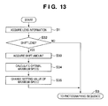
- Fig. 13 is a flowchart illustrating exposure time changing processing corresponding to the lens conditions according to the third embodiment.
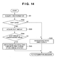
- Fig. 14 is a flowchart illustrating shutter switching processing corresponding to the lens conditions according to the fourth embodiment.
- Embodiments to be described hereinafter are implementation examples of the present invention, and can be appropriately modified or changed in accordance with various conditions and the arrangement of an apparatus to which the present invention is applied. Therefore, the present invention is not particularly limited to the following embodiments.
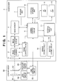
- Fig. 1 is a block diagram showing an image sensing apparatus according to an embodiment of the present invention.
- the image sensing apparatus is, for example, a digital still camera.
- Reference numeral 1 denotes a camera body.
- An image sensing element 2 includes, for example, a CMOS sensor and receives and photoelectrically converts an optical image of an object.
- An image processing circuit 3 performs predetermined pixel interpolation processing and color conversion processing for an electric charge signal from the image sensing element 2 or data from an image memory 4. Using the sensed image data, the image processing circuit 3 performs predetermined arithmetic processing and even TTL AWB (Auto White Balance) processing based on the obtained arithmetic result.
- TTL AWB Automatic White Balance
- the data from the image processing circuit 3 is written into the image memory 4.
- a camera control circuit 5 includes an arithmetic processing circuit such as a CPU and controls the overall camera body 1.
- a timing generation circuit 6 supplies a clock signal and control signal to the image sensing element 2 and image processing circuit 3.
- a release unit 7 performs the release operation of a shutter 14.
- a switch SW1 of the release unit 7 is turned on so that the camera control circuit 5 issues an instruction to start, for example, AF (Auto Focus) processing or AE (Auto Exposure) processing.
- AF Auto Focus
- AE Automatic Exposure
- the shutter button (not shown) is operated completely (pressed fully)
- a switch SW2 of the release unit 7 is turned on so that an electric charge signal read out from the image sensing element 2 is output to the image processing circuit 3.
- An external storage unit 8 such as a hard disk stores photographed image data, and has a storage capacity large enough to store a predetermined number of still images and a moving image for a predetermined time.
- An AF unit 9 adjusts the focus position from focal length information.
- An AE unit 10 performs exposure adjustment from photometric information of an object.
- An external display unit 11 includes, for example, a liquid crystal display panel and displays, for example, the apparatus operation state or a message using, for example, a text, image, or sound in accordance with program execution by the camera control circuit 5.
- a mirror driving circuit 12 moves up or down a mirror which is obliquely inserted in the photographing optical path in a viewfinder observation state and retracted outside the photographing optical path in a photographing state.
- a shutter driving circuit 13 drives the shutter 14.
- the mechanical shutter 14 has a first curtain and second curtain and controls a light beam which enters the image sensing element 2 from a lens main body 50, and performs an image sensing operation by simultaneously using an electronic shutter and the second curtain of the shutter 14 in normal photography. That is, an electronic first curtain and mechanical second curtain are implemented by controlling reset scanning of the image sensing element 2 and travel of the second curtain of the mechanical shutter 14. In switching from the electronic first curtain to the first curtain of the mechanical shutter 14 (to be described later), the first curtain and second curtain of the mechanical shutter 14 limit the exposure time.
- the lens main body 50 is detachably, electrically connected to the camera body 1 via a connector including a communication line and power supply line.
- a photographing lens 51 includes focus lenses and zoom lenses. Although these lenses are illustrated as one lens in Fig. 1 for the sake of convenience, they are formed by complicated combinations of a large number of lenses in practice.
- An aperture 52 adjusts the light amount in photography.
- a lens control circuit 53 includes an arithmetic processing circuit such as a CPU, controls, for example, focus driving and aperture driving (to be described later), and communicates with the camera control circuit 5.
- a lens driving circuit 54 drives the photographing lens in the optical axis direction based on a command from the lens control circuit 53.
- An aperture driving circuit 55 drives the aperture 52 based on a command from the lens control circuit 53.
- the camera control circuit 5 When the switch SW1 of the release unit 7 is turned on, the camera control circuit 5 outputs an AF processing instruction to the AF unit 9, and outputs an AE processing instruction to the AE unit 10.
- the AF unit 9 determines the current defocus state.
- the camera control circuit 5 calculates focal length information from the defocus state, and outputs this information to the lens control circuit 53 of the lens main body 50. Based on the focal length information obtained by the camera control circuit 5, the lens control circuit 53 outputs a control command to the lens driving circuit 54 to drive and focus the photographing lens 51.
- the AE unit 10 measures the current brightness of an object.
- the camera control circuit 5 calculates photometric information from the photometric result, and determines the exposure time and F-number according to the camera setting.
- the camera control circuit 5 After the AF processing and AE processing are completed and the switch SW2 of the release unit 7 is turned on, the camera control circuit 5 outputs a control command to the lens control circuit 53.
- the aperture driving circuit 55 drives the aperture 52 to have a predetermined F-number, in accordance with the command from the lens control circuit 53.
- the camera control circuit 5 outputs a control command to the mirror driving circuit 12 to move a mirror (not shown) from a viewfinder observation state to a photographing state.
- the camera control circuit 5 outputs control commands to the shutter driving circuit 13 and timing generation circuit 6.
- Image sensing is performed by implementing an electronic first curtain and mechanical second curtain by controlling electric charge accumulation start scanning of the image sensing element 2 and travel of the mechanical shutter 14.
- the electric charges accumulated in the image sensing element 2 are sequentially read out to the image processing circuit 3 and undergo image processing by it.
- the processed image data is written into the image memory 4.
- the image data temporarily stored in the image memory 4 are transferred to the external storage unit 8 and recorded in it.
- Fig. 2 is a view of the image sensing element and the second curtain of the mechanical shutter when seen from the lens side along the optical axis direction.
- Fig. 2 shows reset scanning of the electronic first curtain and travel of the mechanical second curtain after photography is started by the release unit 7.
- an arrow 20 indicates both the reset scanning direction (the traveling direction of the electronic first curtain) of the electronic first curtain and the traveling direction of the mechanical second curtain.
- An object image is formed on the image sensing plane of the image sensing element 2 via the lens main body 50.
- Reference numeral 21 indicates the image sensing plane of the image sensing element 2; and 15, the mechanical second curtain of the mechanical shutter 14.
- Fig. 2 shows the state in which the mechanical second curtain 15 partially shields the image sensing plane 21 against light.
- Reference numeral 2a indicates a line (reset line) along which reset scanning of the image sensing element 2 is performed.
- the reset scanning is to reset the amounts of accumulated electric charge of pixels on the reset line 2a to zero, and the reset line 2a corresponds to the leading edge of the electronic first curtain.
- a slit region 22 between the reset line 2a and a leading edge portion 15a of the mechanical second curtain 15 is an image sensing region (electric charge accumulation region) in which the image sensing element 2 accumulates electric charges by exposure.
- the electric charge accumulation region 22 moves in the direction indicated by the arrow 20.
- the time from when the reset line 2a passes through a given pixel of the image sensing element 2, that is, from when reset scanning is started until the mechanical second curtain 15 shields the image sensing element 2 against light is the time for electric charge accumulation of the given pixel by exposure. Since the reset line 2a travels in the direction indicated by the arrow 20 and electric charge accumulation on each line starts, the electric charge accumulation start timing changes for each line of the image sensing element 2.
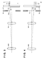
- Figs. 3 and 4 are views each showing the relationship among the mechanical second curtain, the electronic first curtain, and the pupil position of the photographing lens.
- reference numeral 502 denotes a lens having a long focal length and long exit pupil distance; 501, a lens having a short focal length and short exit pupil distance; 16, a shutter base plate; and 17, a shutter blade press.
- FIG. 3 shows the state in which the shutter has begun to open with a maximum speed in a photographing operation.
- a slit width A1 indicates the width of a region formed between the reset line 2a and a line 15a on which the mechanical second curtain 15 shields a light beam from the lens 501 with a short exit pupil distance.
- a slit width B1 indicates the width of a region formed between the reset line 2a and the line 15a on which the mechanical second curtain 15 shields a light beam from the lens 502 with a long exit pupil distance.
- the slit width A1 is wider than the slit width B1.
- exposure using the lens 501 takes a longer time than exposure using the lens 502 in the region with the slit width B1. Therefore, if the reset scanning pattern of the electronic first curtain is set such that the lens 501 can obtain correct exposure, underexposure occurs at the beginning of opening of the shutter upon photography by the lens 502.
- Fig. 4 shows the latter half of a photographing operation (near the end of photography).
- a slit width A2 indicates the width of a region formed between the reset line 2a and the line 15a on which the mechanical second curtain 15 shields a light beam from the lens 501 with a short focal length and short exit pupil distance.
- a slit width B2 indicates the width of a region formed between the reset line 2a and the line 15a on which the mechanical second curtain 15 shields a light beam from the lens 502 with a long focal length and long exit pupil distance.
- the slit width B2 is wider than the slit width A2 in contrast to the beginning of opening of the shutter shown in Fig. 3 .
- exposure using the lens 501 takes a longer time than exposure using the lens 502 in the region with the slit width A2. Therefore, if the reset scanning pattern of the electronic first curtain is set such that the lens 501 can obtain correct exposure, overexposure occurs upon photography by the lens 502.
- an optimal reset scanning timing of the electronic first curtain changes depending on the difference in pupil position.
- a slit width A1' corresponding to a lens 501 with a short exit pupil distance is about twice the slit width A1 shown in Fig. 3 .
- a slit width B1' corresponding to a lens 502 with a long exit pupil distance is shorter than the slit width A1', but the difference between the slit widths A1' and B1' is very small as compared with that between the slit widths A1 and B1 shown in Fig. 3 .
- a slit width A2' corresponding to a lens 501 with a short exit pupil distance is about twice the slit width A2 shown in Fig. 4 .
- a slit width B2' corresponding to a lens 502 with a long exit pupil distance is shorter than the slit width A2', but the difference between the slit widths A2' and B2' is very small as compared with that between the slit widths A2 and B2 shown in Fig. 4 .
- the amount of error with respect to the shutter speed decreases in proportion. That is, the amount of error decreases to 1/2 if the maximum shutter speed is halved, and it decreases to 1/4 if the maximum shutter speed is halved again.
- Figs. 3 and 4 show the state in which the shutter speed is a maximum. Slowing down the shutter speed from the maximum one by two steps makes it possible to eliminate errors of the pupil positions of nearly all the lenses. This is because when the shutter speed slows down to below about 1/2000 seconds, the difference in slit width attributed to the pupil position of each lens becomes negligibly small.
- a camera control circuit 5 acquires information associated with a lens from a lens main body 50 (S1).
- the camera control circuit 5 communicates with a lens control circuit 53 of the lens main body 50 to transmit/receive necessary information on the lens main body 50 mounted on a camera body 1 to/from the lens control circuit 53.
- the camera control circuit 5 determines the lens conditions from the lens information acquired in step S1 (S2). If the camera control circuit 5 determines in step S2 that the lens main body 50 is a normal lens, the processing shifts to a photographing sequence (S3). Then, the camera control circuit 5 sets an optimal traveling characteristic of an electronic first curtain in accordance with the lens information acquired in step S1.
- step S2 If the camera control circuit 5 determines in step S2 that information associated with the lens pupil position is absent or is not found, an optimal traveling characteristic of the electronic first curtain cannot be obtained and an optimal maximum shutter speed is set for all the lenses (S4). More specifically, the maximum shutter speed is slowed down by about two steps. That is, if the maximum shutter speed is 1/8000 seconds, it is slowed down to about 1/2000 seconds. This makes it possible to obtain an appropriate image with low unevenness of exposure, as described with reference to Figs. 5 and 6 .
- the camera control circuit 5 changes the setting value of the maximum speed to the one determined in step S4, and the processing shifts to the photographing sequence (S3).
- the determination in step S2 may be done in accordance with the presence/absence of a device to change the lens pupil position or the presence/absence of an extension tube, in addition to the presence/absence of information associated with the lens pupil position.
- a predetermined shutter speed is set as the maximum shutter speed.
- Shutter switching processing corresponding to the lens conditions according to the second embodiment will be explained next with reference to the sequence illustrated in Fig. 8 .
- the second embodiment is different from the first embodiment in that if a camera control circuit 5 determines in step S2 that a lens main body 50 is not a normal lens, switching is performed from an electronic first curtain to the first curtain of a mechanical shutter in step S25. This makes it possible to obtain an image with correct exposure because the mechanical shutter has no error compared with the electronic first curtain.
- Figs. 9 and 10 are views each showing the relationship between the mechanical second curtain, the electronic first curtain, and the amount of shift of the shift lens.
- the same reference numerals as in Figs. 3 and 4 denote corresponding members in Figs. 9 and 10 .
- reference numeral 601 indicates the state in which a shift lens has not shifted; and 601', the state in which a shift lens has largely shifted.
- Fig. 9 shows the state in which the shutter has begun to open with a maximum speed in a photographing operation.
- a slit width C1 indicates the width of a region formed between a reset line 2a and a line 15a on which a mechanical second curtain 15 shields a light beam from the lens 601 with zero amount of shift.
- a slit width D1 indicates the width of a region formed between the reset line 2a and the line 15a on which the mechanical second curtain 15 shields a light beam from the lens 601' with a large amount of shift.
- the slit width C1 is wider than the slit width D1.
- exposure using the lens 601 with zero amount of shift takes a longer time than exposure using the lens 601' with a large amount of shift in the region with the slit width D1. Therefore, if the reset scanning pattern of the electronic first curtain is set such that the lens 601 with zero amount of shift can obtain correct exposure, underexposure occurs at the beginning of opening of the shutter upon photography by the lens 601'.
- Fig. 10 shows the latter half of a photographing operation (near the end of photography).
- a slit width C2 indicates the width of a region formed between the reset line 2a and the line 15a on which the mechanical second curtain 15 shields a light beam from the lens 601 with zero amount of shift.
- a slit width D2 indicates the width of a region formed between the reset line 2a and the line 15a on which the mechanical second curtain 15 shields a light beam from the lens 601' with a large amount of shift.
- the slit width D2 is shorter than the slit width C2 as in the beginning of opening of the shutter shown in Fig. 9 .
- exposure using the lens 601 with zero amount of shift takes a longer time than exposure using the lens 601' in the region with the slit width D2. Therefore, if the reset scanning pattern of the electronic first curtain is set such that the lens 501 can obtain correct exposure, underexposure occurs at the end of opening of the shutter upon photography by the lens 601' with a large amount of shift.
- a slit width C1' corresponding to a lens 601 with zero amount of shift is about twice the slit width C1 shown in Fig. 9 .
- a slit width D1' corresponding to a lens 601' with a large amount of shift is shorter than the slit width C1' with zero amount of shift, but the difference between the slit widths C1' and D1' is very small as compared with that between the slit widths C1 and D1 shown in Fig. 9 .
- a slit width C2' corresponding to a lens 601 with zero amount of shift is about twice the slit width C2 shown in Fig. 10 .
- a slit width D2' corresponding to a lens 601' with a large amount of shift is shorter than the slit width C2' with zero amount of shift, but the difference between the slit widths C2' and D2' is very small as compared with that between the slit widths C2 and D2 shown in Fig. 10 .
- a camera control circuit 5 determines in step S32 that a lens main body 50 is a shift lens, it acquires the amount of shift from the lens main body 50 (S33).
- the camera control circuit 5 calculates an optimal maximum shutter speed from the amount of shift acquired in step S33 (S34). In this case, the maximum shutter speed is slowed down in accordance with the magnitude of the amount of shift.
- the camera control circuit 5 changes the setting value of the maximum speed to the one calculated in step S34, and the processing shifts to the photographing sequence (S3) (S35).
- the third embodiment when a shift lens is mounted on the apparatus, it is possible to determine and set an optimal maximum shutter speed from the amount of shift. This makes it possible to obtain an image with correct exposure even when a shift lens is used for an electronic first curtain.
- Shutter switching processing corresponding to the lens conditions according to the fourth embodiment will be explained with reference to the sequence illustrated in Fig. 14 .
- the fourth embodiment is different from the third embodiment in the following points. That is, if a camera control circuit 5 determines in steps S32 and S44 that a lens main body 50 is a shift lens (S32) and has an amount of shift equal to or larger than a predetermined value (S44), switching is performed from an electronic first curtain to the first curtain of a mechanical shutter in step S45. If the camera control circuit 5 determines in step S44 that the amount of shift is smaller than the predetermined value, the electronic first curtain is maintained in step S46. The mechanical shutter has no error as in the electronic first curtain. Hence, even when a shift lens is mounted on the apparatus, it is possible to obtain an image with correct exposure by switching to the first curtain of the mechanical shutter if the amount of shift is equal to or larger than the predetermined value.
- switching may be performed to the first curtain of the mechanical shutter as in the case in which a shift lens is mounted on the apparatus.
- a storage medium (or recording medium) which stores software program codes for implementing the functions of the above-described embodiments is supplied to a camera.
- the computer or CPU or MPU
- the computer or CPU or MPU
Landscapes
- Engineering & Computer Science (AREA)
- Multimedia (AREA)
- Signal Processing (AREA)
- Physics & Mathematics (AREA)
- General Physics & Mathematics (AREA)
- Studio Devices (AREA)
- Shutters For Cameras (AREA)
- Transforming Light Signals Into Electric Signals (AREA)
- Exposure Control For Cameras (AREA)
Abstract
Description
- The present invention relates to a photographing control technique which simultaneously uses a mechanical shutter and an electronic shutter.
- A single-lens reflex digital camera incorporates a mechanical focal plane shutter (to be referred to as a mechanical shutter hereinafter) having a first curtain and a second curtain, and limits the exposure time by movement of the first curtain and second curtain in normal photography. There is also proposed a camera which performs an image sensing operation by simultaneously using a mechanical shutter and an electronic shutter. The mechanism which simultaneously uses a mechanical shutter and an electronic shutter uses the mechanical shutter for the second curtain, and takes a photograph by electric charge accumulation by starting scanning of the pixels of an image sensing element prior to travel of the second curtain.
- An image sensing element using a CMOS sensor performs pixel reset (scanning for resetting the accumulated electric charge amount of a pixel to zero) for each pixel or each image sensing region including a plurality of pixels. After a predetermined time has elapsed, signal readout scanning is performed for each pixel or each region, thus implementing an electronic shutter. That is, in such electric charge accumulation of an image sensing element, for each scanning line pixels are reset and electric charge accumulation is started (such electric charge accumulation start scanning will be referred to as reset scanning hereinafter). After that, the second curtain of a mechanical shutter shields the image sensing element against light, and scanning for reading out the electric charges accumulated in the respective pixel elements is performed. Therefore, the pattern of this reset scanning is matched with the traveling characteristic of the mechanical shutter for the second curtain (e.g., Japanese Patent Laid-Open No.
11-41523 Figs. 1 to 3 and the like)). - A general single-lens reflex digital camera uses an exchangeable photographing lens, and can therefore change the focal length and the exit pupil distance (the distance from the image sensing plane to the lens pupil position). Assume that a mechanical shutter and electronic shutter are simultaneously used. The electronic shutter is activated on the image sensing plane, while the mechanical shutter is spaced apart from the image sensing plane in the optical axis direction. For this reason, the light-shielding position, on the image sensing plane, of the mechanical shutter changes depending on, for example, the focal length and exit pupil distance. Particularly when the time from reset scanning until light shielding by the mechanical shutter is relatively short, unevenness of exposure occurs in the shutter scanning direction depending on the conditions of the photographing lens.
- Examples of the conditions of the photographing lens are the presence/absence of pupil position information, whether the lens is a shift lens, the shift amounts of a shift lens and antivibration lens, whether the lens has an accessory adapter for changing the pupil position, and whether an extension tube is attached to the lens. Since the light-shielding position, on the image sensing plane, of the second curtain of the mechanical shutter changes depending on these factors, unevenness of exposure occurs in the shutter scanning direction as described above.
- The present invention has been made in consideration of the above-described problem, and has as its object to provide a technique capable of reducing unevenness of exposure in the shutter scanning direction attributed to the lens conditions when a mechanical shutter and electronic shutter are used together.
- In order to solve the above-described problem, according to the present invention in its first aspect, there is provided an image sensing apparatus as specified in
claims 1 to 6. - According to the present invention in its second aspect, there is also provided a control method for an image sensing apparatus as specified in
claims 7 to 10. - According to the present invention, it is possible to attain a technique for reducing unevenness of exposure in the shutter scanning direction attributed to the lens conditions when a mechanical shutter and electronic shutter are simultaneously used.
- Further features of the present invention will become apparent from the following description of exemplary embodiments (with reference to the attached drawings).
-
Fig. 1 is a block diagram showing an image sensing apparatus according to an embodiment of the present invention; -
Fig. 2 is a view of an image sensing element and the second curtain of a mechanical shutter when seen from the lens side along the optical axis direction; -
Fig. 3 is a view showing the relationship among a mechanical second curtain, an electronic first curtain, and the pupil position of a photographing lens; -
Fig. 4 is a view showing another relationship among the mechanical second curtain, the electronic first curtain, and the pupil position of the photographing lens; -
Fig. 5 is a view showing still another relationship among the mechanical second curtain, the electronic first curtain, and the pupil position of the photographing lens; -
Fig. 6 is a view showing still another relationship among the mechanical second curtain, the electronic first curtain, and the pupil position of the photographing lens; -
Fig. 7 is a flowchart illustrating exposure time changing processing corresponding to the lens conditions according to the first embodiment; -
Fig. 8 is a flowchart illustrating shutter switching processing corresponding to the lens conditions according to the second embodiment; -
Fig. 9 is a view showing the relationship among a mechanical second curtain, an electronic first curtain, and the amount of shift of a shift lens; -
Fig. 10 is a view showing another relationship among the mechanical second curtain, the electronic first curtain, and the amount of shift of the shift lens; -
Fig. 11 is a view showing still another relationship among the mechanical second curtain, the electronic first curtain, and the amount of shift of the shift lens; -
Fig. 12 is a view showing still another relationship among the mechanical second curtain, the electronic first curtain, and the amount of shift of the shift lens; -
Fig. 13 is a flowchart illustrating exposure time changing processing corresponding to the lens conditions according to the third embodiment; and -
Fig. 14 is a flowchart illustrating shutter switching processing corresponding to the lens conditions according to the fourth embodiment. - The present invention will now be described in detail with reference to the accompanying drawings.
- Embodiments to be described hereinafter are implementation examples of the present invention, and can be appropriately modified or changed in accordance with various conditions and the arrangement of an apparatus to which the present invention is applied. Therefore, the present invention is not particularly limited to the following embodiments.
-
Fig. 1 is a block diagram showing an image sensing apparatus according to an embodiment of the present invention. - Referring to
Fig. 1 , the image sensing apparatus according to this embodiment is, for example, a digital still camera.Reference numeral 1 denotes a camera body. - An
image sensing element 2 includes, for example, a CMOS sensor and receives and photoelectrically converts an optical image of an object. - An
image processing circuit 3 performs predetermined pixel interpolation processing and color conversion processing for an electric charge signal from theimage sensing element 2 or data from animage memory 4. Using the sensed image data, theimage processing circuit 3 performs predetermined arithmetic processing and even TTL AWB (Auto White Balance) processing based on the obtained arithmetic result. - The data from the
image processing circuit 3 is written into theimage memory 4. - A
camera control circuit 5 includes an arithmetic processing circuit such as a CPU and controls theoverall camera body 1. - A
timing generation circuit 6 supplies a clock signal and control signal to theimage sensing element 2 andimage processing circuit 3. - A
release unit 7 performs the release operation of ashutter 14. When a shutter button (not shown) is operated midway (pressed halfway), a switch SW1 of therelease unit 7 is turned on so that thecamera control circuit 5 issues an instruction to start, for example, AF (Auto Focus) processing or AE (Auto Exposure) processing. When the shutter button (not shown) is operated completely (pressed fully), a switch SW2 of therelease unit 7 is turned on so that an electric charge signal read out from theimage sensing element 2 is output to theimage processing circuit 3. - An
external storage unit 8 such as a hard disk stores photographed image data, and has a storage capacity large enough to store a predetermined number of still images and a moving image for a predetermined time. - An
AF unit 9 adjusts the focus position from focal length information. - An
AE unit 10 performs exposure adjustment from photometric information of an object. - An
external display unit 11 includes, for example, a liquid crystal display panel and displays, for example, the apparatus operation state or a message using, for example, a text, image, or sound in accordance with program execution by thecamera control circuit 5. - A
mirror driving circuit 12 moves up or down a mirror which is obliquely inserted in the photographing optical path in a viewfinder observation state and retracted outside the photographing optical path in a photographing state. - A
shutter driving circuit 13 drives theshutter 14. - The
mechanical shutter 14 has a first curtain and second curtain and controls a light beam which enters theimage sensing element 2 from a lensmain body 50, and performs an image sensing operation by simultaneously using an electronic shutter and the second curtain of theshutter 14 in normal photography. That is, an electronic first curtain and mechanical second curtain are implemented by controlling reset scanning of theimage sensing element 2 and travel of the second curtain of themechanical shutter 14. In switching from the electronic first curtain to the first curtain of the mechanical shutter 14 (to be described later), the first curtain and second curtain of themechanical shutter 14 limit the exposure time. - The lens
main body 50 is detachably, electrically connected to thecamera body 1 via a connector including a communication line and power supply line. - A photographing
lens 51 includes focus lenses and zoom lenses. Although these lenses are illustrated as one lens inFig. 1 for the sake of convenience, they are formed by complicated combinations of a large number of lenses in practice. - An
aperture 52 adjusts the light amount in photography. - A
lens control circuit 53 includes an arithmetic processing circuit such as a CPU, controls, for example, focus driving and aperture driving (to be described later), and communicates with thecamera control circuit 5. - A
lens driving circuit 54 drives the photographing lens in the optical axis direction based on a command from thelens control circuit 53. - An
aperture driving circuit 55 drives theaperture 52 based on a command from thelens control circuit 53. - The operations of the
camera body 1 and lensmain body 50 will be explained next with reference toFig. 1 . - When the switch SW1 of the
release unit 7 is turned on, thecamera control circuit 5 outputs an AF processing instruction to theAF unit 9, and outputs an AE processing instruction to theAE unit 10. - The
AF unit 9 determines the current defocus state. Thecamera control circuit 5 calculates focal length information from the defocus state, and outputs this information to thelens control circuit 53 of the lensmain body 50. Based on the focal length information obtained by thecamera control circuit 5, thelens control circuit 53 outputs a control command to thelens driving circuit 54 to drive and focus the photographinglens 51. - The
AE unit 10 measures the current brightness of an object. Thecamera control circuit 5 calculates photometric information from the photometric result, and determines the exposure time and F-number according to the camera setting. - After the AF processing and AE processing are completed and the switch SW2 of the
release unit 7 is turned on, thecamera control circuit 5 outputs a control command to thelens control circuit 53. Theaperture driving circuit 55 drives theaperture 52 to have a predetermined F-number, in accordance with the command from thelens control circuit 53. - The
camera control circuit 5 outputs a control command to themirror driving circuit 12 to move a mirror (not shown) from a viewfinder observation state to a photographing state. - The
camera control circuit 5 outputs control commands to theshutter driving circuit 13 andtiming generation circuit 6. Image sensing is performed by implementing an electronic first curtain and mechanical second curtain by controlling electric charge accumulation start scanning of theimage sensing element 2 and travel of themechanical shutter 14. - The electric charges accumulated in the
image sensing element 2 are sequentially read out to theimage processing circuit 3 and undergo image processing by it. The processed image data is written into theimage memory 4. - The image data temporarily stored in the
image memory 4 are transferred to theexternal storage unit 8 and recorded in it. -
Fig. 2 is a view of the image sensing element and the second curtain of the mechanical shutter when seen from the lens side along the optical axis direction.Fig. 2 shows reset scanning of the electronic first curtain and travel of the mechanical second curtain after photography is started by therelease unit 7. - Referring to
Fig. 2 , anarrow 20 indicates both the reset scanning direction (the traveling direction of the electronic first curtain) of the electronic first curtain and the traveling direction of the mechanical second curtain. An object image is formed on the image sensing plane of theimage sensing element 2 via the lensmain body 50.Reference numeral 21 indicates the image sensing plane of theimage sensing element 2; and 15, the mechanical second curtain of themechanical shutter 14.Fig. 2 shows the state in which the mechanicalsecond curtain 15 partially shields theimage sensing plane 21 against light.Reference numeral 2a indicates a line (reset line) along which reset scanning of theimage sensing element 2 is performed. - The reset scanning is to reset the amounts of accumulated electric charge of pixels on the
reset line 2a to zero, and thereset line 2a corresponds to the leading edge of the electronic first curtain. - A
slit region 22 between thereset line 2a and aleading edge portion 15a of the mechanicalsecond curtain 15 is an image sensing region (electric charge accumulation region) in which theimage sensing element 2 accumulates electric charges by exposure. As the electronic first curtain and mechanical second curtain travel, the electriccharge accumulation region 22 moves in the direction indicated by thearrow 20. The time from when thereset line 2a passes through a given pixel of theimage sensing element 2, that is, from when reset scanning is started until the mechanicalsecond curtain 15 shields theimage sensing element 2 against light is the time for electric charge accumulation of the given pixel by exposure. Since thereset line 2a travels in the direction indicated by thearrow 20 and electric charge accumulation on each line starts, the electric charge accumulation start timing changes for each line of theimage sensing element 2. - The reason why the exposure time changes depending on the pupil position of the lens
main body 50 will be explained next with reference toFigs. 3 and 4 . -
Figs. 3 and 4 are views each showing the relationship among the mechanical second curtain, the electronic first curtain, and the pupil position of the photographing lens. - Referring to
Figs. 3 and 4 ,reference numeral 502 denotes a lens having a long focal length and long exit pupil distance; 501, a lens having a short focal length and short exit pupil distance; 16, a shutter base plate; and 17, a shutter blade press. -
Fig. 3 shows the state in which the shutter has begun to open with a maximum speed in a photographing operation. A slit width A1 indicates the width of a region formed between thereset line 2a and aline 15a on which the mechanicalsecond curtain 15 shields a light beam from thelens 501 with a short exit pupil distance. A slit width B1 indicates the width of a region formed between thereset line 2a and theline 15a on which the mechanicalsecond curtain 15 shields a light beam from thelens 502 with a long exit pupil distance. - At the timing shown in
Fig. 3 , the slit width A1 is wider than the slit width B1. When the electronic first curtain and mechanical second curtain are driven under the same conditions, exposure using thelens 501 takes a longer time than exposure using thelens 502 in the region with the slit width B1. Therefore, if the reset scanning pattern of the electronic first curtain is set such that thelens 501 can obtain correct exposure, underexposure occurs at the beginning of opening of the shutter upon photography by thelens 502. -
Fig. 4 shows the latter half of a photographing operation (near the end of photography). A slit width A2 indicates the width of a region formed between thereset line 2a and theline 15a on which the mechanicalsecond curtain 15 shields a light beam from thelens 501 with a short focal length and short exit pupil distance. A slit width B2 indicates the width of a region formed between thereset line 2a and theline 15a on which the mechanicalsecond curtain 15 shields a light beam from thelens 502 with a long focal length and long exit pupil distance. - At the timing shown in
Fig. 4 , the slit width B2 is wider than the slit width A2 in contrast to the beginning of opening of the shutter shown inFig. 3 . When the electronic first curtain and mechanical second curtain are driven under the same conditions, exposure using thelens 501 takes a longer time than exposure using thelens 502 in the region with the slit width A2. Therefore, if the reset scanning pattern of the electronic first curtain is set such that thelens 501 can obtain correct exposure, overexposure occurs upon photography by thelens 502. - For the above-described reason, an optimal reset scanning timing of the electronic first curtain changes depending on the difference in pupil position.
- A case in which the exposure time is prolonged, that is, the shutter speed is slowed down to reduce the above-described unevenness of exposure will be explained with reference to
Figs. 5 and 6 . - The same reference numerals as in
Figs. 3 and 4 denote the corresponding members inFigs. 5 and 6 . - Referring to
Fig. 5 , a slit width A1' corresponding to alens 501 with a short exit pupil distance is about twice the slit width A1 shown inFig. 3 . A slit width B1' corresponding to alens 502 with a long exit pupil distance is shorter than the slit width A1', but the difference between the slit widths A1' and B1' is very small as compared with that between the slit widths A1 and B1 shown inFig. 3 . - Likewise, referring to
Fig. 6 , a slit width A2' corresponding to alens 501 with a short exit pupil distance is about twice the slit width A2 shown inFig. 4 . A slit width B2' corresponding to alens 502 with a long exit pupil distance is shorter than the slit width A2', but the difference between the slit widths A2' and B2' is very small as compared with that between the slit widths A2 and B2 shown inFig. 4 . - Slowing down the shutter speed reduces unevenness of exposure due to the difference in pupil position. In addition, the amount of error with respect to the shutter speed decreases in proportion. That is, the amount of error decreases to 1/2 if the maximum shutter speed is halved, and it decreases to 1/4 if the maximum shutter speed is halved again.
-
Figs. 3 and 4 show the state in which the shutter speed is a maximum. Slowing down the shutter speed from the maximum one by two steps makes it possible to eliminate errors of the pupil positions of nearly all the lenses. This is because when the shutter speed slows down to below about 1/2000 seconds, the difference in slit width attributed to the pupil position of each lens becomes negligibly small. - Maximum shutter speed changing processing corresponding to the lens conditions according to the first embodiment will be explained with reference to the sequence illustrated in
Fig. 7 . - Referring to
Fig. 7 , when the processing starts, acamera control circuit 5 acquires information associated with a lens from a lens main body 50 (S1). Thecamera control circuit 5 communicates with alens control circuit 53 of the lensmain body 50 to transmit/receive necessary information on the lensmain body 50 mounted on acamera body 1 to/from thelens control circuit 53. - The
camera control circuit 5 determines the lens conditions from the lens information acquired in step S1 (S2). If thecamera control circuit 5 determines in step S2 that the lensmain body 50 is a normal lens, the processing shifts to a photographing sequence (S3). Then, thecamera control circuit 5 sets an optimal traveling characteristic of an electronic first curtain in accordance with the lens information acquired in step S1. - If the
camera control circuit 5 determines in step S2 that information associated with the lens pupil position is absent or is not found, an optimal traveling characteristic of the electronic first curtain cannot be obtained and an optimal maximum shutter speed is set for all the lenses (S4). More specifically, the maximum shutter speed is slowed down by about two steps. That is, if the maximum shutter speed is 1/8000 seconds, it is slowed down to about 1/2000 seconds. This makes it possible to obtain an appropriate image with low unevenness of exposure, as described with reference toFigs. 5 and 6 . - The
camera control circuit 5 changes the setting value of the maximum speed to the one determined in step S4, and the processing shifts to the photographing sequence (S3). - The determination in step S2 may be done in accordance with the presence/absence of a device to change the lens pupil position or the presence/absence of an extension tube, in addition to the presence/absence of information associated with the lens pupil position.
- More specifically, if a device to change the lens pupil position or an extension tube is absent, a predetermined shutter speed is set as the maximum shutter speed.
- Shutter switching processing corresponding to the lens conditions according to the second embodiment will be explained next with reference to the sequence illustrated in
Fig. 8 . - The same reference signs as in
Fig. 7 denote the corresponding processing operations inFig. 8 . - The second embodiment is different from the first embodiment in that if a
camera control circuit 5 determines in step S2 that a lensmain body 50 is not a normal lens, switching is performed from an electronic first curtain to the first curtain of a mechanical shutter in step S25. This makes it possible to obtain an image with correct exposure because the mechanical shutter has no error compared with the electronic first curtain. - The reason why the exposure time changes depending on the amount of shift of a shift lens will be explained next with reference to
Figs. 9 and 10 . -
Figs. 9 and 10 are views each showing the relationship between the mechanical second curtain, the electronic first curtain, and the amount of shift of the shift lens. The same reference numerals as inFigs. 3 and 4 denote corresponding members inFigs. 9 and 10 . - Referring to
Figs. 9 and 10 ,reference numeral 601 indicates the state in which a shift lens has not shifted; and 601', the state in which a shift lens has largely shifted. -
Fig. 9 shows the state in which the shutter has begun to open with a maximum speed in a photographing operation. A slit width C1 indicates the width of a region formed between areset line 2a and aline 15a on which a mechanicalsecond curtain 15 shields a light beam from thelens 601 with zero amount of shift. A slit width D1 indicates the width of a region formed between thereset line 2a and theline 15a on which the mechanicalsecond curtain 15 shields a light beam from the lens 601' with a large amount of shift. - At the timing shown in
Fig. 9 , the slit width C1 is wider than the slit width D1. When the electronic first curtain and mechanical second curtain are driven under the same conditions, exposure using thelens 601 with zero amount of shift takes a longer time than exposure using the lens 601' with a large amount of shift in the region with the slit width D1. Therefore, if the reset scanning pattern of the electronic first curtain is set such that thelens 601 with zero amount of shift can obtain correct exposure, underexposure occurs at the beginning of opening of the shutter upon photography by the lens 601'. -
Fig. 10 shows the latter half of a photographing operation (near the end of photography). A slit width C2 indicates the width of a region formed between thereset line 2a and theline 15a on which the mechanicalsecond curtain 15 shields a light beam from thelens 601 with zero amount of shift. A slit width D2 indicates the width of a region formed between thereset line 2a and theline 15a on which the mechanicalsecond curtain 15 shields a light beam from the lens 601' with a large amount of shift. - At the timing shown in
Fig. 10 , the slit width D2 is shorter than the slit width C2 as in the beginning of opening of the shutter shown inFig. 9 . When the electronic first curtain and mechanical second curtain are driven under the same conditions, exposure using thelens 601 with zero amount of shift takes a longer time than exposure using the lens 601' in the region with the slit width D2. Therefore, if the reset scanning pattern of the electronic first curtain is set such that thelens 501 can obtain correct exposure, underexposure occurs at the end of opening of the shutter upon photography by the lens 601' with a large amount of shift. - A case in which the exposure time is prolonged, that is, the shutter speed is slowed down to reduce the above-described unevenness of exposure will be explained with reference to
Figs. 11 and 12 . - The same reference numerals as in
Figs. 9 and 10 denote the corresponding members inFigs. 11 and 12 . - Referring to
Fig. 11 , a slit width C1' corresponding to alens 601 with zero amount of shift is about twice the slit width C1 shown inFig. 9 . A slit width D1' corresponding to a lens 601' with a large amount of shift is shorter than the slit width C1' with zero amount of shift, but the difference between the slit widths C1' and D1' is very small as compared with that between the slit widths C1 and D1 shown inFig. 9 . - Likewise, referring to
Fig. 12 , a slit width C2' corresponding to alens 601 with zero amount of shift is about twice the slit width C2 shown inFig. 10 . A slit width D2' corresponding to a lens 601' with a large amount of shift is shorter than the slit width C2' with zero amount of shift, but the difference between the slit widths C2' and D2' is very small as compared with that between the slit widths C2 and D2 shown inFig. 10 . - Even when a shift lens is used, slowing down the shutter speed reduces unevenness of exposure due to the difference in pupil position as in the case described with reference to
Figs. 5 and 6 . - Maximum shutter speed changing processing corresponding to the lens conditions according to the third embodiment will be explained with reference to the sequence illustrated in
Fig. 13 . - The same reference signs as in
Fig. 7 denote the corresponding processing operations inFig. 13 . - In the third embodiment, if a
camera control circuit 5 determines in step S32 that a lensmain body 50 is a shift lens, it acquires the amount of shift from the lens main body 50 (S33). - The
camera control circuit 5 calculates an optimal maximum shutter speed from the amount of shift acquired in step S33 (S34). In this case, the maximum shutter speed is slowed down in accordance with the magnitude of the amount of shift. - The
camera control circuit 5 changes the setting value of the maximum speed to the one calculated in step S34, and the processing shifts to the photographing sequence (S3) (S35). - According to the third embodiment, when a shift lens is mounted on the apparatus, it is possible to determine and set an optimal maximum shutter speed from the amount of shift. This makes it possible to obtain an image with correct exposure even when a shift lens is used for an electronic first curtain.
- Shutter switching processing corresponding to the lens conditions according to the fourth embodiment will be explained with reference to the sequence illustrated in
Fig. 14 . - The same reference signs as in
Fig. 13 denote the corresponding processing operations inFig. 14 . - The fourth embodiment is different from the third embodiment in the following points. That is, if a
camera control circuit 5 determines in steps S32 and S44 that a lensmain body 50 is a shift lens (S32) and has an amount of shift equal to or larger than a predetermined value (S44), switching is performed from an electronic first curtain to the first curtain of a mechanical shutter in step S45. If thecamera control circuit 5 determines in step S44 that the amount of shift is smaller than the predetermined value, the electronic first curtain is maintained in step S46.
The mechanical shutter has no error as in the electronic first curtain. Hence, even when a shift lens is mounted on the apparatus, it is possible to obtain an image with correct exposure by switching to the first curtain of the mechanical shutter if the amount of shift is equal to or larger than the predetermined value. - If a device to change the lens pupil position or an extension tube is absent, switching may be performed to the first curtain of the mechanical shutter as in the case in which a shift lens is mounted on the apparatus.
- The object of the present invention is also achieved by the following method. A storage medium (or recording medium) which stores software program codes for implementing the functions of the above-described embodiments is supplied to a camera. In this case, the computer (or CPU or MPU) of the camera reads out and executes the program codes from the storage medium.
- When the present invention is applied to the above-described storage medium, it stores various tables and control programs for executing the processing operations of the flowcharts illustrated in
Figs. 7 ,8 ,13 and14 described above. These program codes can be provided even as, for example, updateable firmware. - While the present invention has been described with reference to exemplary embodiments, it is to be understood that the invention is not limited to the disclosed exemplary embodiments. The scope of the following claims is to be accorded the broadest interpretation so as to encompass all such modifications and equivalent structures and functions.
Claims (12)
- An image sensing apparatus comprising:image sensing means (2) having one or more image sensing regions (22) adapted to receive an object image via said lens and accumulate the received image as an electric charge;a mechanical shutter (14) adapted to travel so as to shield the one or more image sensing regions (22) against light;scanning means (5,6) adapted to perform scanning for sequentially starting the accumulation of the electric charge for each one or more image sensing regions of said image sensing means;control means (5) adapted to control the scanning of said scanning means and said mechanical shutter, so as to provide an electronic first curtain and a mechanical second curtain (15); andchanging means (5) adapted to change the maximum shutter speed on the basis of information about a lens mounted to the image sensing apparatus.
- An image sensing apparatus comprising:image sensing means (2) having one or more image sensing regions (22) adapted to receive an object image via said lens and accumulate the received image as an electric charge;a mechanical shutter (14) which includes a first curtain and second curtain (15) adapted to travel so as to shield the one or more image sensing regions against light;scanning means (5,6) adapted to perform scanning for sequentially starting the accumulation of the electric charge for each one or more image sensing region of said image sensing means;control means (5) adapted to control the scanning for starting the accumulation of the electric charge and the travel of said mechanical shutter, so as to implement an electronic first curtain and mechanical second curtain; andswitching means (5) adapted to switch the first curtain of the shutter from an electronic first curtain to a mechanical first curtain on the basis of information about a lens mounted to the image sensing apparatus.
- The apparatus according to claim 1, wherein said changing means slows down the maximum shutter speed if one or more of the following occurs: the type of the lens is a shift lens (601,601'), information on a pupil position of the lens is not found, a shift amount of the shift lens is not found, a device to change the pupil position of the lens is absent, or an extension tube is absent.
- The apparatus according to claim 2, wherein said switching means switches the first curtain of the shutter to said first curtain of said mechanical shutter if one or more of the following occurs: the type of the lens is a shift lens (601,601'), information on a pupil position of the lens is not found, a shift amount of the shift lens is not found, a device to change the pupil position of the lens is absent, or an extension tube is absent.
- An image sensing apparatus as claimed in any preceding claim in which the information about the lens is the type of lens.
- An image sensing apparatus as claimed in any preceding claim including a lens mounted thereto.
- A control method for an image sensing apparatus which comprises:an image sensing unit adapted to receive an object image via a lens and accumulate the received image as an electric charge;a mechanical shutter unit adapted to travel so as to shield an image sensing region of the image sensing unit against light;a scanning unit adapted to perform scanning for sequentially starting the accumulation of the electric charge for each image sensing region of the image sensing unit; anda control unit adapted to control the accumulation start scanning of the scanning unit and the travel of a shutter of the mechanical shutter unit, so as to implement a first curtain and second curtain (5) of a shutter, the method comprising:changing a maximum shutter speed on the basis of at least one of: the type of the lens and information on the lens.
- A control method for an image sensing apparatus which comprises:an image sensing unit (2) adapted to receive an object image via a lens and accumulate the received image as an electric charge;a mechanical shutter unit (14) which includes a first curtain and second curtain (15) and is adapted to travel so as to shield an image sensing region of the image sensing unit against light;a scanning unit adapted to perform scanning for sequentially starting the accumulation of the electric charge for each image sensing region of the image sensing unit; anda control unit adapted to control the scanning for starting the accumulation of the electric charge and the travel of the mechanical shutter unit, so as to implement a first curtain and second curtain of a shutter, the method comprising:switching the first curtain of the shutter from an electronic first curtain to the first curtain of the mechanical shutter unit on the basis of at least one of: the type of the lens and information on the lens (S25) .
- The method according to claim 7, wherein in the changing step, the maximum shutter speed is slowed down (S34, S35) if one or more of the following occurs: the type of the lens is a shift lens (S32), information on a pupil position of the lens is not found, a shift amount of the shift lens is not found, a device to change the pupil position of the lens is absent, or an extension tube is absent.
- The method according to claim 8, wherein in the switching step, the first curtain of the shutter is switched from an electronic first curtain to the first curtain of the mechanical shutter (S45) if one or more of the following occurs: the type of the lens is a shift lens (S32), information on a pupil position of the lens is not found, a shift amount of the shift lens is not found (S44), a device to change the pupil position of the lens is absent, or an extension tube is absent.
- A computer program which when loaded into a computer of a camera performs a method as claimed in any one of claims 7 to 10.
- A machine-readable storage medium storing a computer program as claimed in claim 11.
Applications Claiming Priority (1)
| Application Number | Priority Date | Filing Date | Title |
|---|---|---|---|
| JP2007149644A JP5335202B2 (en) | 2007-06-05 | 2007-06-05 | Imaging apparatus and control method thereof |
Publications (2)
| Publication Number | Publication Date |
|---|---|
| EP2015563A1 true EP2015563A1 (en) | 2009-01-14 |
| EP2015563B1 EP2015563B1 (en) | 2010-11-17 |
Family
ID=39744728
Family Applications (1)
| Application Number | Title | Priority Date | Filing Date |
|---|---|---|---|
| EP08157682A Not-in-force EP2015563B1 (en) | 2007-06-05 | 2008-06-05 | Image sensing apparatus and control method therefor |
Country Status (5)
| Country | Link |
|---|---|
| US (1) | US7918616B2 (en) |
| EP (1) | EP2015563B1 (en) |
| JP (1) | JP5335202B2 (en) |
| CN (1) | CN101321229A (en) |
| DE (1) | DE602008003486D1 (en) |
Families Citing this family (7)
| Publication number | Priority date | Publication date | Assignee | Title |
|---|---|---|---|---|
| KR101170459B1 (en) | 2009-11-03 | 2012-08-07 | 삼성전자주식회사 | Method Of Controlling Imaging Apparatus And Imaging Apparatus Using the Same |
| KR20110076729A (en) * | 2009-12-18 | 2011-07-06 | 삼성전자주식회사 | Multi-level exposure image acquisition method using an electronic shutter and photographing apparatus using the same |
| JP2011191616A (en) * | 2010-03-16 | 2011-09-29 | Panasonic Corp | Imaging device |
| JP5402857B2 (en) * | 2010-07-05 | 2014-01-29 | 株式会社ニコン | Imaging device and lens barrel |
| JP5621569B2 (en) | 2010-12-13 | 2014-11-12 | ソニー株式会社 | Imaging apparatus and shutter operation correction method |
| CN102685392A (en) * | 2011-03-07 | 2012-09-19 | 精工爱普生株式会社 | Digital camera and shutter operation estimating method |
| CN113014913B (en) * | 2019-12-19 | 2022-09-06 | 合肥君正科技有限公司 | Method for detecting shielding of in-vehicle monitoring camera in segmented mode |
Citations (4)
| Publication number | Priority date | Publication date | Assignee | Title |
|---|---|---|---|---|
| JPH1141523A (en) | 1997-07-17 | 1999-02-12 | Nikon Corp | Imaging device |
| WO2006036921A1 (en) * | 2004-09-28 | 2006-04-06 | Eastman Kodak Company | Image capturing device |
| WO2007011002A1 (en) * | 2005-07-22 | 2007-01-25 | Canon Kabushiki Kaisha | Image sensing apparatus |
| US20070116453A1 (en) * | 2005-11-24 | 2007-05-24 | Canon Kabushiki Kaisha | Optical apparatus |
Family Cites Families (3)
| Publication number | Priority date | Publication date | Assignee | Title |
|---|---|---|---|---|
| JP2842604B2 (en) | 1989-02-10 | 1999-01-06 | 旭光学工業株式会社 | Exposure control device for camera with interval function |
| CA2065984C (en) * | 1991-04-15 | 2001-07-31 | Osamu Sato | Exposure control apparatus of camera |
| JP2007033543A (en) * | 2005-07-22 | 2007-02-08 | Fujifilm Holdings Corp | Imaging apparatus |
-
2007
- 2007-06-05 JP JP2007149644A patent/JP5335202B2/en not_active Expired - Fee Related
-
2008
- 2008-05-21 US US12/124,787 patent/US7918616B2/en not_active Expired - Fee Related
- 2008-06-05 DE DE602008003486T patent/DE602008003486D1/en active Active
- 2008-06-05 CN CNA2008101112028A patent/CN101321229A/en active Pending
- 2008-06-05 EP EP08157682A patent/EP2015563B1/en not_active Not-in-force
Patent Citations (4)
| Publication number | Priority date | Publication date | Assignee | Title |
|---|---|---|---|---|
| JPH1141523A (en) | 1997-07-17 | 1999-02-12 | Nikon Corp | Imaging device |
| WO2006036921A1 (en) * | 2004-09-28 | 2006-04-06 | Eastman Kodak Company | Image capturing device |
| WO2007011002A1 (en) * | 2005-07-22 | 2007-01-25 | Canon Kabushiki Kaisha | Image sensing apparatus |
| US20070116453A1 (en) * | 2005-11-24 | 2007-05-24 | Canon Kabushiki Kaisha | Optical apparatus |
Also Published As
| Publication number | Publication date |
|---|---|
| JP2008304565A (en) | 2008-12-18 |
| EP2015563B1 (en) | 2010-11-17 |
| DE602008003486D1 (en) | 2010-12-30 |
| US20080304820A1 (en) | 2008-12-11 |
| CN101321229A (en) | 2008-12-10 |
| US7918616B2 (en) | 2011-04-05 |
| JP5335202B2 (en) | 2013-11-06 |
Similar Documents
| Publication | Publication Date | Title |
|---|---|---|
| JP5003543B2 (en) | Imaging apparatus, signal processing method, and computer program | |
| JP5693355B2 (en) | Imaging apparatus, control method therefor, program, and storage medium | |
| US7844176B2 (en) | Imaging device, and control method for imaging device | |
| EP2015563B1 (en) | Image sensing apparatus and control method therefor | |
| JP2001186401A (en) | Digital camera | |
| CN101373254B (en) | Imaging device, and control method for imaging device | |
| JP5709629B2 (en) | Imaging apparatus and control method | |
| JP3632677B2 (en) | Electronic camera | |
| JP5333888B2 (en) | Imaging apparatus and program thereof | |
| JP2010072320A (en) | Camera | |
| JP4863370B2 (en) | Imaging device | |
| JP7458715B2 (en) | Photographic device, its control method, program, and recording medium | |
| US9172857B2 (en) | Image capture apparatus, imaging lens, and image capture system | |
| JP7229709B2 (en) | Imaging device and its control method | |
| JP5451058B2 (en) | IMAGING DEVICE, IMAGING DEVICE CONTROL METHOD, IMAGING DEVICE CONTROL PROGRAM | |
| JP2009122557A (en) | Camera | |
| JP2007060131A (en) | Camera with live view display function | |
| JP4827526B2 (en) | Optical equipment | |
| JP4906590B2 (en) | Imaging device | |
| JP2011135193A (en) | Imaging apparatus, and control method | |
| JP2007251656A (en) | Imaging apparatus, control method thereof, and program | |
| JP4061642B2 (en) | Electronic camera | |
| JP2006174023A (en) | Imaging device | |
| JP2000307923A (en) | Imaging device, method, and computer-readable storage medium | |
| JP2003149536A (en) | Camera |
Legal Events
| Date | Code | Title | Description |
|---|---|---|---|
| PUAI | Public reference made under article 153(3) epc to a published international application that has entered the european phase |
Free format text: ORIGINAL CODE: 0009012 |
|
| PUAI | Public reference made under article 153(3) epc to a published international application that has entered the european phase |
Free format text: ORIGINAL CODE: 0009012 |
|
| AK | Designated contracting states |
Kind code of ref document: A1 Designated state(s): AT BE BG CH CY CZ DE DK EE ES FI FR GB GR HR HU IE IS IT LI LT LU LV MC MT NL NO PL PT RO SE SI SK TR |
|
| AX | Request for extension of the european patent |
Extension state: AL BA MK RS |
|
| 17P | Request for examination filed |
Effective date: 20090714 |
|
| AKX | Designation fees paid |
Designated state(s): DE FR GB IT |
|
| 17Q | First examination report despatched |
Effective date: 20091120 |
|
| GRAP | Despatch of communication of intention to grant a patent |
Free format text: ORIGINAL CODE: EPIDOSNIGR1 |
|
| GRAS | Grant fee paid |
Free format text: ORIGINAL CODE: EPIDOSNIGR3 |
|
| GRAA | (expected) grant |
Free format text: ORIGINAL CODE: 0009210 |
|
| AK | Designated contracting states |
Kind code of ref document: B1 Designated state(s): DE FR GB IT |
|
| REG | Reference to a national code |
Ref country code: GB Ref legal event code: FG4D |
|
| REF | Corresponds to: |
Ref document number: 602008003486 Country of ref document: DE Date of ref document: 20101230 Kind code of ref document: P |
|
| PLBE | No opposition filed within time limit |
Free format text: ORIGINAL CODE: 0009261 |
|
| STAA | Information on the status of an ep patent application or granted ep patent |
Free format text: STATUS: NO OPPOSITION FILED WITHIN TIME LIMIT |
|
| 26N | No opposition filed |
Effective date: 20110818 |
|
| REG | Reference to a national code |
Ref country code: DE Ref legal event code: R097 Ref document number: 602008003486 Country of ref document: DE Effective date: 20110818 |
|
| REG | Reference to a national code |
Ref country code: FR Ref legal event code: PLFP Year of fee payment: 9 |
|
| PGFP | Annual fee paid to national office [announced via postgrant information from national office to epo] |
Ref country code: GB Payment date: 20160627 Year of fee payment: 9 |
|
| PGFP | Annual fee paid to national office [announced via postgrant information from national office to epo] |
Ref country code: IT Payment date: 20160608 Year of fee payment: 9 Ref country code: FR Payment date: 20160627 Year of fee payment: 9 |
|
| PGFP | Annual fee paid to national office [announced via postgrant information from national office to epo] |
Ref country code: DE Payment date: 20160630 Year of fee payment: 9 |
|
| REG | Reference to a national code |
Ref country code: DE Ref legal event code: R119 Ref document number: 602008003486 Country of ref document: DE |
|
| GBPC | Gb: european patent ceased through non-payment of renewal fee |
Effective date: 20170605 |
|
| REG | Reference to a national code |
Ref country code: FR Ref legal event code: ST Effective date: 20180228 |
|
| PG25 | Lapsed in a contracting state [announced via postgrant information from national office to epo] |
Ref country code: GB Free format text: LAPSE BECAUSE OF NON-PAYMENT OF DUE FEES Effective date: 20170605 Ref country code: DE Free format text: LAPSE BECAUSE OF NON-PAYMENT OF DUE FEES Effective date: 20180103 |
|
| PG25 | Lapsed in a contracting state [announced via postgrant information from national office to epo] |
Ref country code: FR Free format text: LAPSE BECAUSE OF NON-PAYMENT OF DUE FEES Effective date: 20170630 Ref country code: IT Free format text: LAPSE BECAUSE OF NON-PAYMENT OF DUE FEES Effective date: 20170605 |