EP2015406A2 - Electrical connector assembly and male connector - Google Patents
Electrical connector assembly and male connector Download PDFInfo
- Publication number
- EP2015406A2 EP2015406A2 EP08104706A EP08104706A EP2015406A2 EP 2015406 A2 EP2015406 A2 EP 2015406A2 EP 08104706 A EP08104706 A EP 08104706A EP 08104706 A EP08104706 A EP 08104706A EP 2015406 A2 EP2015406 A2 EP 2015406A2
- Authority
- EP
- European Patent Office
- Prior art keywords
- retainer
- male
- female
- housing
- connector
- Prior art date
- Legal status (The legal status is an assumption and is not a legal conclusion. Google has not performed a legal analysis and makes no representation as to the accuracy of the status listed.)
- Withdrawn
Links
- 238000003780 insertion Methods 0.000 claims abstract description 29
- 230000037431 insertion Effects 0.000 claims abstract description 29
- 230000013011 mating Effects 0.000 claims description 56
- 238000005192 partition Methods 0.000 claims description 13
- 210000000078 claw Anatomy 0.000 abstract description 34
- 230000002093 peripheral effect Effects 0.000 description 8
- 230000007423 decrease Effects 0.000 description 3
- 230000003247 decreasing effect Effects 0.000 description 3
- 239000011347 resin Substances 0.000 description 3
- 229920005989 resin Polymers 0.000 description 3
- 230000000149 penetrating effect Effects 0.000 description 2
- 238000010276 construction Methods 0.000 description 1
- 238000000034 method Methods 0.000 description 1
- 238000000465 moulding Methods 0.000 description 1
- 230000002265 prevention Effects 0.000 description 1
Images



Classifications
-
- H—ELECTRICITY
- H01—ELECTRIC ELEMENTS
- H01R—ELECTRICALLY-CONDUCTIVE CONNECTIONS; STRUCTURAL ASSOCIATIONS OF A PLURALITY OF MUTUALLY-INSULATED ELECTRICAL CONNECTING ELEMENTS; COUPLING DEVICES; CURRENT COLLECTORS
- H01R13/00—Details of coupling devices of the kinds covered by groups H01R12/70 or H01R24/00 - H01R33/00
- H01R13/40—Securing contact members in or to a base or case; Insulating of contact members
- H01R13/42—Securing in a demountable manner
- H01R13/436—Securing a plurality of contact members by one locking piece or operation
- H01R13/4361—Insertion of locking piece perpendicular to direction of contact insertion
- H01R13/4362—Insertion of locking piece perpendicular to direction of contact insertion comprising a temporary and a final locking position
-
- H—ELECTRICITY
- H01—ELECTRIC ELEMENTS
- H01R—ELECTRICALLY-CONDUCTIVE CONNECTIONS; STRUCTURAL ASSOCIATIONS OF A PLURALITY OF MUTUALLY-INSULATED ELECTRICAL CONNECTING ELEMENTS; COUPLING DEVICES; CURRENT COLLECTORS
- H01R13/00—Details of coupling devices of the kinds covered by groups H01R12/70 or H01R24/00 - H01R33/00
- H01R13/62—Means for facilitating engagement or disengagement of coupling parts or for holding them in engagement
- H01R13/627—Snap or like fastening
-
- H—ELECTRICITY
- H01—ELECTRIC ELEMENTS
- H01R—ELECTRICALLY-CONDUCTIVE CONNECTIONS; STRUCTURAL ASSOCIATIONS OF A PLURALITY OF MUTUALLY-INSULATED ELECTRICAL CONNECTING ELEMENTS; COUPLING DEVICES; CURRENT COLLECTORS
- H01R13/00—Details of coupling devices of the kinds covered by groups H01R12/70 or H01R24/00 - H01R33/00
- H01R13/64—Means for preventing incorrect coupling
-
- H—ELECTRICITY
- H01—ELECTRIC ELEMENTS
- H01R—ELECTRICALLY-CONDUCTIVE CONNECTIONS; STRUCTURAL ASSOCIATIONS OF A PLURALITY OF MUTUALLY-INSULATED ELECTRICAL CONNECTING ELEMENTS; COUPLING DEVICES; CURRENT COLLECTORS
- H01R12/00—Structural associations of a plurality of mutually-insulated electrical connecting elements, specially adapted for printed circuits, e.g. printed circuit boards [PCB], flat or ribbon cables, or like generally planar structures, e.g. terminal strips, terminal blocks; Coupling devices specially adapted for printed circuits, flat or ribbon cables, or like generally planar structures; Terminals specially adapted for contact with, or insertion into, printed circuits, flat or ribbon cables, or like generally planar structures
- H01R12/70—Coupling devices
- H01R12/7005—Guiding, mounting, polarizing or locking means; Extractors
- H01R12/7011—Locking or fixing a connector to a PCB
Definitions
- the present invention relates to an electrical connector assembly comprising a female connector having a female housing and a male connector that mates with the female connector and has a male housing accommodated in the female housing.
- an electrical connector assembly comprising a female connector and a male connector that mates with the female connector has been used to electrically connect a circuit board in an electronic device for a vehicle to electric wires.
- the female connector generally includes a female housing and a plurality of male contacts that are installed in the female housing and are connected to the circuit board.
- the male connector generally includes a male housing accommodated in the female housing and female contacts that are installed in the male housing and each connected to the electric wire, and come into contact with the male contacts.
- a lance is provided in the male connector housing or the female contact.
- the male connector must naturally be downsized.
- the density of internal structure thereof is increased, so that the female contact is downsized.
- the size of the lance is also decreased. If the size of the lance is decreased, a force capable of holding the female contact decreases, so that the function of preventing the female contacts from coming off also decreases. Also, if the size of the lance is decreased, there arises a problem in that it is difficult to mold the lance by using molding dies.
- a male connector 5 includes a lance block 3 for pre-latching a female contact 1 in a male housing 2 and a retainer 4 for latching the female contact 1, which has been pre-latched by the lance block 3, to the male housing 2 as shown in FIG. 9
- Japanese Patent Application No. 2006-155018 Japanese Patent Application No. 2006-155018
- the lance block 3 is first installed in the male housing 2.
- the female contact 1 is then inserted into a contact slot 6 formed in the male housing 2.
- the female contact 1 in the contact slot 6 is pre-latched by the lance block 3.
- the retainer 4 is installed in the female housing 2, and the female contact 1 is latched.
- the female contact 1 is latched to the male housing 2 by the lance block 3 and the retainer 4 in a state of being inserted into the contact slot 6.
- the lance block 3 and the retainer 4 are not pushed completely into the male housing 2 in some cases. In such a case, the lance block 3 and the retainer 4 project from the male housing 2, so that usually, the male connector 5 cannot be inserted into the female connector 7.
- the male connector 5 can sometimes be inserted into the female connector 7 if the lance block 3 and the retainer 4 are pushed in forcedly because the female housing 8 of the female connector 7 is made of a resin and therefore has elasticity.
- the female contact 1 is not fixed in the male housing 2 reliably, so that the engagement of the female contact 1 with a male contact 9 on the female connector 7 side may be incomplete.
- the male connector 5 is formed by the three parts, that is, the male housing 2, the lance block 3, and the retainer 4, the assembling manpower increases.
- the present art still has room for improvement in terms of the increase in work efficiency and the increase in the reliability due to complete engagement of the male contact with the female contact.
- the present invention has been made to solve the above technical problems, and accordingly an object thereof is to provide an electrical connector assembly in which a male contact is reliably engaged with a female contact to increase the reliability and work efficiency and to provide a male connector used in such an electrical connector assembly.
- the electrical connector assembly in accordance with the present invention that has been made to achieve the above object includes a female connector and a male connector mating with the female connector.
- the female connector includes a female housing having a mating recess that accommodates the male connector and a plurality of male contacts held by the female housing.
- the male connector includes a male housing inserted into the mating recess, a plurality of female contacts capable of being electrically connected to the male contacts, and a retainer that is mounted in the male housing to hold the female contacts.
- the male housing there is formed a slot into which the retainer is inserted in the direction perpendicular to the direction in which the male housing is inserted into the mating recess.
- the retainer can be locked in the slot at a first position at which the retainer does not project from the male housing and can be into the mating recess in the female housing and a second position at which a part of the retainer projects from the male housing by 1/2 times of an arrangement pitch p of the female contacts held by the retainer and interferes with the female housing when the retainer is inserted into the mating recess.
- the female contacts are installed to the retainer in the state in which the retainer is locked at the second position.
- a part of the retainer having been inserted into the slot projects from the male housing.
- the projecting direction is perpendicular to the direction in which the male housing is inserted into the mating recess. If the worker makes an attempt to mistakenly insert the male connectors into the mating recess in the female connector in this state, the projecting retainer interferes with the female connector. Therefore, in this state, the male connector cannot mate with the female connector.
- the retainer If the retainer is locked in the slot at the first position, the retainer does not project from the male housing. If the male connector is inserted into the mating recess in the female connector in this state, the male connector can mate with the female connector without interference of the retainer with the female housing. Therefore, the female connector and the male connector can be electrically connected to each other.
- the female contacts held by the retainer are misaligned with the female contacts at the first position. Even if the worker makes an attempt to insert the male connector into the mating recess in the female connector in this state, the female contacts and the male contacts cannot be connected to each other because the female contacts of the male connector and the male contacts of the female connector are misaligned with each other. Therefore, when the retainer lies at the second position, the female contacts and the male contacts cannot physically be connected to each other. Therefore, even if the worker makes an attempt to forcedly mate the male housing with the female housing, wrong contact between the female contacts and the male contacts can be prevented.
- the retainer is configured so as to be inserted along the arrangement direction of the female contacts held by the retainer.
- the mating recess in the female connector generally has a rectangular shape that is long in the arrangement direction of the female contacts. If the retainer is inserted along the arrangement direction of the female contacts, at the second position, a part of the retainer interferes with the short side of the mating recess in the female connector.
- the short side of the female housing has a higher rigidity and therefore is less liable to be deformed than the long side thereof, so that if the retainer is in a projected state, the retainer surely interferes with the female contacts.
- the tip end surface of the male housing there are formed a plurality of insertion holes into which the male contacts are inserted one by one when the male housing is inserted into the mating recess.
- the retainer is formed with a plurality of contact slots for holding the female contacts one by one, and partitions are formed between the adjacent contact slots.
- the male contacts of the female connector are guided to correct positions by the insertion holes.
- the retainer is at the second position, even if the worker makes an attempt to insert the male connector into the mating recess in the female connector, the female contacts of the male connector and the male contacts of the female connector are misaligned with each other. Even if the worker makes an attempt to insert the male connector into the mating recess in the female connector in the state in which the female contacts and the male contacts are misaligned with each other, since the male contacts are positioned by the insertion holes in the male housing, the male contacts can be prevented from being deformed inadvertently.
- the insertion holes in the male housing are closed by the partitions of the retainer. Therefore, the male connector positioned by the insertion holes in the male housing interferes with the interpole walls, so that the insertion of the male contacts into the contact slot in the retainer is blocked. Therefore, even if the worker makes an attempt to mate the male connector with the female connector when the retainer is at the second position, wrong contact between the female contacts and the male contacts can be prevented.
- the retainer In the state in which the retainer is locked at the second position, even if the worker makes an attempt to insert the male connector into the mating recess in the female connector, the retainer projecting from the male housing interferes with the female housing. If the worker makes an attempt to insert the male connector into the mating recess in the female connector in this state, the worker gets to know the interference of the retainer with the female housing, and therefore can recognize that the retainer is in a state of being locked at the second position.
- the retainer interferes with the female housing immediately after the male connector has begun to be inserted into the mating recess in the female connector. Therefore, the worker can early recognize that the retainer is in a state of being locked at the second position.
- the present invention can be applied to only the male connector mated with the mating recess in the female connector.
- This male connector includes a male housing inserted into the mating recess, a plurality of female contacts capable of being electrically connected to male contacts of the female connector, and a retainer that is mounted in the male housing to hold the female contacts.
- the male housing there is formed a slot in which the retainer is inserted in the direction perpendicular to the direction in which the male housing is inserted into the mating recess, and in the tip end surface of the male housing, there are formed a plurality of insertion holes in which the plurality of male contacts are inserted one by one when the male housing is inserted into the mating recess.
- the retainer can be locked in the slot at a first position at which the retainer does not project from the male housing and can be inserted into the mating recess in the female housing and a second position at which a part of the retainer projects from the male housing by 1/2 times of an arrangement pitch p of the female contacts held by the retainer and interferes with the female housing when the retainer is inserted into the mating recess, and also the retainer is provided with a plurality of contact slots for holding the female contacts one by one, and partitions are formed between the adjacent contact slots.
- the retainer in the state in which the retainer is locked at the second position, since a part of the retainer inserted into the slot projects from a convex part, even if the worker makes an attempt to insert the male connector into the mating recess in the female connector in this state, the projecting retainer interferes with the female housing. Therefore, in this state, the male connector cannot mate with the female connector. As a result, the male connector can be prevented from being mistakenly mated with the female connector in the state in which the retainer is locked at the second position, and therefore the reliability of work can be enhanced.
- the female contacts held by the retainer are misaligned with the female contacts at the first position.
- the retainer lies at the second position, even if the worker makes an attempt to mistakenly mate the male connector with the female connector, wrong contact between the female contacts and the male contacts can be prevented because the female contacts and the male contacts are misaligned with each other. In this respect as well, the reliability of work can be enhanced.
- the male contacts of the female connector can be positioned at the correct positions. This also contributes to the prevention of wrong contact between the female contacts and the male contacts.
- the male contacts are caused to interfere with the partitions even if the worker makes an attempt to mate the male connector with the female connector when the retainer lies at the second position. As a result, wrong contact between the female contacts and the male contacts can be prevented.
- the retainer In the state in which the retainer is locked at the second position, even if the worker makes an attempt to insert the male connectors into the mating recess in the female connector, the projecting retainer interferes with the female housing. If the worker makes an attempt to insert the male connector into the mating recess in the female connector in this state, the worker gets to know the interference of the retainer with the female housing, and therefore can recognize that the retainer is in a state of being locked at the second position.
- an electrical connector assembly 10 comprises a female connector 20 and a male connector 30.
- the female connector 20 includes a female housing 21 formed of an insulative resin and a plurality of male contacts 22 provided in the female housing 21.
- the female housing 21 is formed with a mating recess 23 for accommodating a male housing 40 in one surface 21a side thereof.
- ridges 23a extending in the insertion/removal direction of the male housing 40 are formed.
- a plurality of contact slots 24 penetrating from the other surface 21b side of the female housing 21 to the mating recess 23 are formed at a predetermined interval.
- the male contacts 22 are held by the female housing 21 by being fitted in the contact slots 24.
- a peg 25 for fixing the female housing 21 to a printed wiring board (not shown) is provided.
- the male connector 30 includes the male housing 40 that is formed of an insulative resin and is inserted into the mating recess 23 formed in the female housing 21, a plurality of female contacts 50 capable of being electrically connected to the male contacts 22, and a retainer 60 for securing the female contacts 50 to the female housing 40.
- the male housing 40 has a convex part 41 having a cross-sectional shape corresponding to the cross-sectional shape of the mating recess 23 of the female housing 21.
- guide grooves 41a that are continuous in the insertion/removal direction of the male housing 40 with respect to the mating recess 23 are formed.
- the guide grooves 41a engage with the ridges 23a in the mating recess 23, by which the male housing 40 is guided in the insertion/removal direction of the male housing 40 with respect to the mating recess 23.
- the guide grooves 41a and the ridges 23a have a function as a key for preventing wrong engagement so that the male housing 40 and the female housing 21 are engaged with each other in a correct combination.
- a locking claw 41b that engages with a locking recess (not shown) formed in the inner peripheral surface of the mating recess 23 is provided.
- the convex part 41 is inserted into the mating recess 23, and the locking claw 41b is locked to the locking concave part in the mating recess 23, by which the female housing 21 and the male housing 40 that have been engaged with each other are locked.
- a retainer slot (slot) 42 extending in the direction perpendicular to the insertion/removal direction of the male housing 40 with respect to the female housing 21 is formed.
- the retainer slot 42 is formed so as to be open to a side surface 41c of the convex part 41.
- An end part 42a of the retainer slot 42 is located in the vicinity of a tip end part 41d of the convex part 41.
- a ridge 42b extending in the same direction as that of the retainer slot 42 is formed.
- a plurality of insertion holes 43 in which the male contacts 22 are inserted are formed at the same interval as that of the male contacts 22 held in the female housing 21 of the female connector 20.
- an opening 45 penetrating from the other surface 40b to the retainer slot 42 is formed.
- the opening 45 electric wires 100 to be connected to the female contacts 50 are inserted.
- the opening 45 is formed into a slit shape extending in the slide direction of the retainer 60 so that the retainer 60 can be slid in the state in which the female contacts 50 connected to the tip end parts of the electric wires 100 are held by the retainer 60.
- the retainer 60 has a cross-sectional shape corresponding to the cross-sectional shape of the retainer slot 42 in the male housing 40 so as to be capable of being inserted into the retainer slot 42.
- a plurality of contact slots 61 for holding the female contacts 50 are formed at a predetermined interval.
- a lance 65 that locks the female contact 50 is formed, so that in the contact slot 61, the tip end part of the female contact 50 is held so as to be located in almost the same plane as a side surface 60a of the retainer 60.
- the contact slots 61 are partitioned from each other by partitions 62.
- Each of the partitions 62 is formed so as to have a cross section capable of closing the insertion hole 43 on the side surface 60a of the retainer 60.
- a part 60b facing to the ridge 42b of the retainer slot 42 is open.
- a locking convex part 63 for locking the retainer 60 having been inserted into the retainer slot 42 and a lock claw 64 for preventing the retainer 60 from coming off the retainer slot 42 are provided.
- locking claws 46 and 47 are formed at positions corresponding to the locking convex part 63 and the lock claw 64, respectively.
- a first locking claw 46A and a second locking claw 46B are provided at two locations spaced along the insertion/removal direction of the retainer 60 with respect to the retainer slot 42.
- the first locking claw 46A is formed at a position at which the retainer 60 projects from the side surface 41c of the convex part 41 of the male housing 40 as shown in FIG. 5 (a second position) in a state of being engaged with the locking convex part 63 of the retainer 60 inserted into the retainer slot 42 (this state is referred to as a pre-latched state).
- the first locking claw 46A is formed so that the projection dimension from the side surface 41c of the retainer 60 is 1/2 times of an arrangement pitch p of the adjacent contact slots 61 (hereinafter, this dimension is referred to as a half pitch).
- the second locking claw 46B is formed at a position at which the retainer 60 does not project from the side surface 41c of the convex part 41 of the male housing 40 (a first position) in a state of being engaged with the locking convex part 63 of the retainer 60 inserted into the retainer slot 42 (this state is referred to as a latched state).
- the locking claw 47 is formed at a position at which it engages with the lock claw 64 in the pre-latched state in which the first locking claw 46A engages with the locking convex part 63.
- the locking claw 47 and the lock claw 64 are formed so as to engage with each other more deeply than the engagement state of the first locking claw 46A with the locking convex part 63.
- the reason for this is that the retainer 60 that is in the pre-latched state in which the first locking claw 46A engages with the locking convex part 63 is prevented from coming off the retainer slot 42.
- FIG. 7A is a cross-section showing a positional relationship between the lock claw 64 and the locking claw 47 in the pre-latched state
- FIG. 7B is a cross-section showing a positional relationship between the lock claw 64 and the locking claw 47 in the latched state.
- the retainer 60 is inserted into the retainer slot 42, and the first locking claw 46A is engaged with the locking convex part 63, by which the pre-latched state is formed.
- the retainer 60 projects by the half pitch from the side surface 41c of the convex part 41 of the male housing 40.
- the contact slots 61 in the retainer 60 and the insertion holes 43 in the male housing 40 also are misaligned with each other by the half pitch, and the partitions 62 are located at the positions facing to the insertion holes 43.
- the female contacts 50 installed to the end parts of the electric wires 100 are inserted into the contact slots 61 in the retainer 60 through the opening 45 in the male housing 40, and the female contacts 50 are pre-latched by the lances 65 formed in the contact slots 61 in the retainer 60.
- the retainer 60 is pushed in completely, and the locking convex part 63 is engaged with the second locking claw 46B, by which the latched state is formed.
- the retainer 60 does not project from the side surface 41c of the convex part 41 of the male housing 40, and is located so as to be approximately flush with the side surface 41c or in an inner part of the convex part 41 beyond the side surface 41c.
- the contact slot 61 in the retainer 60 and the insertion hole 43 in the male housing 40 continue on one straight line. As a result, the female contact 50 held in the contact slot 61 faces to the insertion hole 43 in the male housing 40.
- the assembled male connector 30 mates with the female connector 20 that has been assembled separately.
- the convex part 41 of the male housing 40 is inserted into the mating recess 23 in the female housing 21.
- the male contacts 22 of the female connector 20 are inserted into the female contacts 50 in the retainer 60 through the insertion holes 43 in the male housing 40.
- the retainer 60 projects from the side surface 41c of the convex part 41 of the male housing 40.
- the side surface 60a of the projecting retainer 60 collides with the female housing 21 of the female connector 20, and the retainer 60 cannot be pushed further into the mating recess 23. Therefore, the worker can surely get to know that the retainer 60 is in the pre-latched state.
- the contact slots 61 in the retainer 60 and the insertion holes 43 in the male housing 40 are misaligned with each other by the half pitch, and the partitions 62 of the retainer 60 are located so as to face to the insertion holes 43. Therefore, the male contacts 22 collide with the partitions 62 through the insertion holes 43, and are not connected to the female contacts 50. Thereby, incomplete engagement of the female contacts 22 with the female contacts 50 can be prevented.
- the configuration is made such that there is provided the retainer 60 that is inserted into the direction perpendicular to the insertion/removal direction of the male connector 30 with respect to the female connector 20, and further the retainer 60 can be locked at two stages of the pre-latched state and the latched state with respect to the male housing 40 by the first locking claw 46A and the second locking claw 46B.
- the male contacts 22 and the female contacts 50 can reliably be connected electrically to each other.
- the retainer 60 is in the pre-latched state, wrong contact between the male contacts 22 and the female contacts 50 is prevented, and also if the worker makes an attempt to mate the male connector 30 with the female connector 20 mistakenly, the worker can early get to know this fact. Therefore, an inadvertent work loss can be avoided, and the work efficiency can be improved.
Landscapes
- Connector Housings Or Holding Contact Members (AREA)
- Details Of Connecting Devices For Male And Female Coupling (AREA)
Abstract
Description
- The present invention relates to an electrical connector assembly comprising a female connector having a female housing and a male connector that mates with the female connector and has a male housing accommodated in the female housing.
- Conventionally, an electrical connector assembly comprising a female connector and a male connector that mates with the female connector has been used to electrically connect a circuit board in an electronic device for a vehicle to electric wires. The female connector generally includes a female housing and a plurality of male contacts that are installed in the female housing and are connected to the circuit board. On the other hand, the male connector generally includes a male housing accommodated in the female housing and female contacts that are installed in the male housing and each connected to the electric wire, and come into contact with the male contacts.
- In recent years, it has been required that such an electrical connector assembly used to electrically connect such a circuit board in an electronic device for a vehicle to electric wires be downsized.
- To prevent the female contacts from coming off the male connector, a lance is provided in the male connector housing or the female contact. To meet the requirement for downsizing the electrical connector assembly, the male connector must naturally be downsized. To downsize the male connector, the density of internal structure thereof is increased, so that the female contact is downsized. As a result, the size of the lance is also decreased. If the size of the lance is decreased, a force capable of holding the female contact decreases, so that the function of preventing the female contacts from coming off also decreases. Also, if the size of the lance is decreased, there arises a problem in that it is difficult to mold the lance by using molding dies.
- Thereupon, the applicant of the present invention has already proposed an electrical connector assembly having a configuration in which a male connector 5 includes a lance block 3 for pre-latching a
female contact 1 in a male housing 2 and a retainer 4 for latching thefemale contact 1, which has been pre-latched by the lance block 3, to the male housing 2 as shown inFIG. 9 (Japanese Patent Application No.2006-155018 female contact 1 in the male housing 2, the lance block 3 is first installed in the male housing 2. Thefemale contact 1 is then inserted into acontact slot 6 formed in the male housing 2. In this state, thefemale contact 1 in thecontact slot 6 is pre-latched by the lance block 3. Thereafter, the retainer 4 is installed in the female housing 2, and thefemale contact 1 is latched. Thus, thefemale contact 1 is latched to the male housing 2 by the lance block 3 and the retainer 4 in a state of being inserted into thecontact slot 6. - In the electrical connector assembly, although it goes without saying that the downsizing is needed, it is essential that the electrical conduction between the male contact and the female contact be established reliably. From the viewpoint of reliable electrical conduction between the male contact and the female contact, it has been found by the inventors that the electrical connector assembly shown in
FIG. 9 , in which thefemale contact 1 is fixed to the male housing 2 by the lance block 3 and the retainer 4, has problems described below. - When the male connector 5 to which the
female contact 1 has been installed is inserted into and engaged with a female connector 7, the lance block 3 and the retainer 4 are not pushed completely into the male housing 2 in some cases. In such a case, the lance block 3 and the retainer 4 project from the male housing 2, so that usually, the male connector 5 cannot be inserted into the female connector 7. - However, the fact that the lance block 3 and the retainer 4 have not been pushed in completely becomes clear when the male connector 5 is inserted into the female connector 7 and the lance block 3 and the retainer 4 which project from the male housing 2 come into contact with a female housing 8 of the female connector 7. In the case where the fact that the lance block 3 and the retainer 4 have not been pushed in completely becomes clear, the male connector 5 is pulled out of the female connector 7. After the lance block 3 and the retainer 4 have been pushed in and engaged with the male housing 2 reliably, the male connector 5 is again inserted into the female connector 7. This procedure decreases the work efficiency.
- Also, even if the lance block 3 and the retainer 4 have not been pushed in completely and project from the male housing 2, the male connector 5 can sometimes be inserted into the female connector 7 if the lance block 3 and the retainer 4 are pushed in forcedly because the female housing 8 of the female connector 7 is made of a resin and therefore has elasticity. In this case, the
female contact 1 is not fixed in the male housing 2 reliably, so that the engagement of thefemale contact 1 with a male contact 9 on the female connector 7 side may be incomplete. - Furthermore, since the male connector 5 is formed by the three parts, that is, the male housing 2, the lance block 3, and the retainer 4, the assembling manpower increases.
- As described above, the present art still has room for improvement in terms of the increase in work efficiency and the increase in the reliability due to complete engagement of the male contact with the female contact.
- The present invention has been made to solve the above technical problems, and accordingly an object thereof is to provide an electrical connector assembly in which a male contact is reliably engaged with a female contact to increase the reliability and work efficiency and to provide a male connector used in such an electrical connector assembly.
- The electrical connector assembly in accordance with the present invention that has been made to achieve the above object includes a female connector and a male connector mating with the female connector. The female connector includes a female housing having a mating recess that accommodates the male connector and a plurality of male contacts held by the female housing. The male connector includes a male housing inserted into the mating recess, a plurality of female contacts capable of being electrically connected to the male contacts, and a retainer that is mounted in the male housing to hold the female contacts.
- In the male housing, there is formed a slot into which the retainer is inserted in the direction perpendicular to the direction in which the male housing is inserted into the mating recess.
- The retainer can be locked in the slot at a first position at which the retainer does not project from the male housing and can be into the mating recess in the female housing and a second position at which a part of the retainer projects from the male housing by 1/2 times of an arrangement pitch p of the female contacts held by the retainer and interferes with the female housing when the retainer is inserted into the mating recess.
- In such an electrical connector assembly, the female contacts are installed to the retainer in the state in which the retainer is locked at the second position. At the second position, a part of the retainer having been inserted into the slot projects from the male housing. The projecting direction is perpendicular to the direction in which the male housing is inserted into the mating recess. If the worker makes an attempt to mistakenly insert the male connectors into the mating recess in the female connector in this state, the projecting retainer interferes with the female connector. Therefore, in this state, the male connector cannot mate with the female connector.
- If the retainer is locked in the slot at the first position, the retainer does not project from the male housing. If the male connector is inserted into the mating recess in the female connector in this state, the male connector can mate with the female connector without interference of the retainer with the female housing. Therefore, the female connector and the male connector can be electrically connected to each other.
- At the second position, the female contacts held by the retainer are misaligned with the female contacts at the first position. Even if the worker makes an attempt to insert the male connector into the mating recess in the female connector in this state, the female contacts and the male contacts cannot be connected to each other because the female contacts of the male connector and the male contacts of the female connector are misaligned with each other. Therefore, when the retainer lies at the second position, the female contacts and the male contacts cannot physically be connected to each other. Therefore, even if the worker makes an attempt to forcedly mate the male housing with the female housing, wrong contact between the female contacts and the male contacts can be prevented.
- Also, the retainer is configured so as to be inserted along the arrangement direction of the female contacts held by the retainer. The mating recess in the female connector generally has a rectangular shape that is long in the arrangement direction of the female contacts. If the retainer is inserted along the arrangement direction of the female contacts, at the second position, a part of the retainer interferes with the short side of the mating recess in the female connector. The short side of the female housing has a higher rigidity and therefore is less liable to be deformed than the long side thereof, so that if the retainer is in a projected state, the retainer surely interferes with the female contacts.
- Also, in the electrical connector assembly in accordance with the present invention, in the tip end surface of the male housing, there are formed a plurality of insertion holes into which the male contacts are inserted one by one when the male housing is inserted into the mating recess. Further, the retainer is formed with a plurality of contact slots for holding the female contacts one by one, and partitions are formed between the adjacent contact slots.
- Thereby, when the male connector is inserted into the mating recess in the female connector, the male contacts of the female connector are guided to correct positions by the insertion holes. When the retainer is at the second position, even if the worker makes an attempt to insert the male connector into the mating recess in the female connector, the female contacts of the male connector and the male contacts of the female connector are misaligned with each other. Even if the worker makes an attempt to insert the male connector into the mating recess in the female connector in the state in which the female contacts and the male contacts are misaligned with each other, since the male contacts are positioned by the insertion holes in the male housing, the male contacts can be prevented from being deformed inadvertently.
- Also, when the retainer is at the second position, the insertion holes in the male housing are closed by the partitions of the retainer. Therefore, the male connector positioned by the insertion holes in the male housing interferes with the interpole walls, so that the insertion of the male contacts into the contact slot in the retainer is blocked. Therefore, even if the worker makes an attempt to mate the male connector with the female connector when the retainer is at the second position, wrong contact between the female contacts and the male contacts can be prevented.
- In the state in which the retainer is locked at the second position, even if the worker makes an attempt to insert the male connector into the mating recess in the female connector, the retainer projecting from the male housing interferes with the female housing. If the worker makes an attempt to insert the male connector into the mating recess in the female connector in this state, the worker gets to know the interference of the retainer with the female housing, and therefore can recognize that the retainer is in a state of being locked at the second position.
- If the configuration is made such that at this time, the tip end parts of the female contacts held by the retainer and the side surface of the retainer are located in almost the same plane, and the side surface of the retainer is located in the vicinity of the tip end part of the male housing in the state in which a part of the retainer projects from the male housing at the second position, the retainer interferes with the female housing immediately after the male connector has begun to be inserted into the mating recess in the female connector. Therefore, the worker can early recognize that the retainer is in a state of being locked at the second position.
- The present invention can be applied to only the male connector mated with the mating recess in the female connector. This male connector includes a male housing inserted into the mating recess, a plurality of female contacts capable of being electrically connected to male contacts of the female connector, and a retainer that is mounted in the male housing to hold the female contacts. In the male housing, there is formed a slot in which the retainer is inserted in the direction perpendicular to the direction in which the male housing is inserted into the mating recess, and in the tip end surface of the male housing, there are formed a plurality of insertion holes in which the plurality of male contacts are inserted one by one when the male housing is inserted into the mating recess. The retainer can be locked in the slot at a first position at which the retainer does not project from the male housing and can be inserted into the mating recess in the female housing and a second position at which a part of the retainer projects from the male housing by 1/2 times of an arrangement pitch p of the female contacts held by the retainer and interferes with the female housing when the retainer is inserted into the mating recess, and also the retainer is provided with a plurality of contact slots for holding the female contacts one by one, and partitions are formed between the adjacent contact slots.
- According to the present invention, in the state in which the retainer is locked at the second position, since a part of the retainer inserted into the slot projects from a convex part, even if the worker makes an attempt to insert the male connector into the mating recess in the female connector in this state, the projecting retainer interferes with the female housing. Therefore, in this state, the male connector cannot mate with the female connector. As a result, the male connector can be prevented from being mistakenly mated with the female connector in the state in which the retainer is locked at the second position, and therefore the reliability of work can be enhanced.
- Also, by making the space between the second position and the
first position 1/2 times of the arrangement pitch p of the female contacts held by the retainer, at the second position, the female contacts held by the retainer are misaligned with the female contacts at the first position. As a result, when the retainer lies at the second position, even if the worker makes an attempt to mistakenly mate the male connector with the female connector, wrong contact between the female contacts and the male contacts can be prevented because the female contacts and the male contacts are misaligned with each other. In this respect as well, the reliability of work can be enhanced. - By forming, in the male housing, the plurality of insertion holes in which the male contacts are inserted one by one when the male housing is inserted into the mating recess and by closing portions between the adjacent insertion holes by the partitions, the male contacts of the female connector can be positioned at the correct positions. This also contributes to the prevention of wrong contact between the female contacts and the male contacts.
- By forming, in the retainer, the plurality of contact slots for holding the female contacts one by one and by forming the partitions between the adjacent contact slots, the male contacts are caused to interfere with the partitions even if the worker makes an attempt to mate the male connector with the female connector when the retainer lies at the second position. As a result, wrong contact between the female contacts and the male contacts can be prevented.
- In the state in which the retainer is locked at the second position, even if the worker makes an attempt to insert the male connectors into the mating recess in the female connector, the projecting retainer interferes with the female housing. If the worker makes an attempt to insert the male connector into the mating recess in the female connector in this state, the worker gets to know the interference of the retainer with the female housing, and therefore can recognize that the retainer is in a state of being locked at the second position.
- At this time, if the end part on the tip end side of the retainer is positioned in the vicinity of the tip end part of the male housing in the state in which a part of the retainer projects at the second position, the worker can early recognize that the retainer is in a state of being locked at the second position. As a result, the work efficiency is increased.
-
-
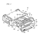
FIG. 1 is a perspective view showing a configuration of an electrical connector assembly in accordance with one embodiment of the present invention, showing a state in which a male connector is about to mate with a female connector in a state in which a retainer projects from the male connector; -
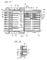
FIG. 2A is a cross-section showing a state in which a male connector is about to mate with a female connector when a retainer is in a pre-latched state, andFIG. 2B is an enlarged cross-section of an essential portion ofFIG. 2A , showing a positional relationship between an insertion hole of a male housing and a female contact at the time when the retainer is in the pre-latched state; -
FIG. 3 is a perspective view showing a male housing and a retainer; -
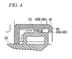
FIG. 4 is a cross-section showing a positional relationship between the locking convex part of a retainer and first and second locking claws of a male housing; -
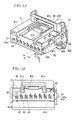
FIG. 5A is a perspective view showing a pre-latched state in which a retainer projects from a male connector, andFIG. 5B is a front view showing a pre-latched state in which the retainer projects from the male connector; -
FIG. 6A is a perspective view showing a latched state in which a retainer does not project from a male connector, andFIG. 6B is a cross-section showing a latched state in which the retainer does not project from the male connector; -
FIG. 7A is a cross-section showing a positional relationship between a lock claw and a locking claw at the time when a retainer is in a pre-latched state, andFIG. 7B is a cross-section showing a positional relationship between the lock claw and the locking claw at the time when the retainer is in a latched state; -
FIG. 8A is a cross-section showing a state in which a male connector mates with a female connector when a retainer is in a latched state, andFIG. 8B is an enlarged cross-section of an essential portion ofFIG. 8A , showing a positional relationship between a male contact and a female contact at the time when the retainer is in a latched state; and -
FIG. 9 is a cross-section showing an example of a conventional contact. - The present invention will now be described in detail based on an embodiment shown in the accompanying drawings.
- As shown in
FIGS. 1 and2 , anelectrical connector assembly 10 comprises afemale connector 20 and amale connector 30. - The
female connector 20 includes afemale housing 21 formed of an insulative resin and a plurality ofmale contacts 22 provided in thefemale housing 21. - As shown in
FIG. 2 , thefemale housing 21 is formed with amating recess 23 for accommodating amale housing 40 in onesurface 21a side thereof. On the inner peripheral surface of themating recess 23,ridges 23a extending in the insertion/removal direction of themale housing 40 are formed. - Also, in the
female housing 21, a plurality ofcontact slots 24 penetrating from theother surface 21b side of thefemale housing 21 to themating recess 23 are formed at a predetermined interval. Themale contacts 22 are held by thefemale housing 21 by being fitted in thecontact slots 24. - Further, on the outer peripheral surface of the
female housing 21, apeg 25 for fixing thefemale housing 21 to a printed wiring board (not shown) is provided. - The
male connector 30 includes themale housing 40 that is formed of an insulative resin and is inserted into themating recess 23 formed in thefemale housing 21, a plurality offemale contacts 50 capable of being electrically connected to themale contacts 22, and aretainer 60 for securing thefemale contacts 50 to thefemale housing 40. - As shown in
FIGS. 2 and3 , themale housing 40 has aconvex part 41 having a cross-sectional shape corresponding to the cross-sectional shape of themating recess 23 of thefemale housing 21. On the outer peripheral surface of theconvex part 41,guide grooves 41a that are continuous in the insertion/removal direction of themale housing 40 with respect to themating recess 23 are formed. Theguide grooves 41a engage with theridges 23a in themating recess 23, by which themale housing 40 is guided in the insertion/removal direction of themale housing 40 with respect to themating recess 23. Also, theguide grooves 41a and theridges 23a have a function as a key for preventing wrong engagement so that themale housing 40 and thefemale housing 21 are engaged with each other in a correct combination. - On the outer peripheral surface of the
convex part 41, a lockingclaw 41b that engages with a locking recess (not shown) formed in the inner peripheral surface of themating recess 23 is provided. Theconvex part 41 is inserted into themating recess 23, and the lockingclaw 41b is locked to the locking concave part in themating recess 23, by which thefemale housing 21 and themale housing 40 that have been engaged with each other are locked. - In the
male housing 40, a retainer slot (slot) 42 extending in the direction perpendicular to the insertion/removal direction of themale housing 40 with respect to thefemale housing 21 is formed. Theretainer slot 42 is formed so as to be open to aside surface 41c of theconvex part 41. Anend part 42a of theretainer slot 42 is located in the vicinity of atip end part 41d of theconvex part 41. Also, on the inner peripheral surface of theretainer slot 42, aridge 42b extending in the same direction as that of theretainer slot 42 is formed. - In the
tip end surface 40a of themale housing 40, a plurality of insertion holes 43 in which themale contacts 22 are inserted are formed at the same interval as that of themale contacts 22 held in thefemale housing 21 of thefemale connector 20. - Further, in the
male housing 40, anopening 45 penetrating from theother surface 40b to theretainer slot 42 is formed. In theopening 45,electric wires 100 to be connected to thefemale contacts 50 are inserted. Also, theopening 45 is formed into a slit shape extending in the slide direction of theretainer 60 so that theretainer 60 can be slid in the state in which thefemale contacts 50 connected to the tip end parts of theelectric wires 100 are held by theretainer 60. - As shown in
FIG. 3 , theretainer 60 has a cross-sectional shape corresponding to the cross-sectional shape of theretainer slot 42 in themale housing 40 so as to be capable of being inserted into theretainer slot 42. In theretainer 60, a plurality ofcontact slots 61 for holding thefemale contacts 50 are formed at a predetermined interval. In each of thecontact slots 61, alance 65 that locks thefemale contact 50 is formed, so that in thecontact slot 61, the tip end part of thefemale contact 50 is held so as to be located in almost the same plane as aside surface 60a of theretainer 60. - The
contact slots 61 are partitioned from each other bypartitions 62. Each of thepartitions 62 is formed so as to have a cross section capable of closing theinsertion hole 43 on theside surface 60a of theretainer 60. - Also, for the
contact slot 61 formed in theretainer 60, apart 60b facing to theridge 42b of theretainer slot 42 is open. When theretainer 60 is inserted into theretainer slot 42, theridge 42b engages with thepart 60b, and locks thefemale contacts 50 held by thecontact slots 61. - On the outer peripheral surface of the
retainer 60, a lockingconvex part 63 for locking theretainer 60 having been inserted into theretainer slot 42 and alock claw 64 for preventing theretainer 60 from coming off theretainer slot 42 are provided. - On the other hand, on the inner peripheral surface of the
retainer slot 42, lockingclaws convex part 63 and thelock claw 64, respectively. As shown inFIG. 4 , as the lockingclaw 46 engaging with the lockingconvex part 63, afirst locking claw 46A and asecond locking claw 46B are provided at two locations spaced along the insertion/removal direction of theretainer 60 with respect to theretainer slot 42. - The
first locking claw 46A is formed at a position at which theretainer 60 projects from theside surface 41c of theconvex part 41 of themale housing 40 as shown inFIG. 5 (a second position) in a state of being engaged with the lockingconvex part 63 of theretainer 60 inserted into the retainer slot 42 (this state is referred to as a pre-latched state). Thefirst locking claw 46A is formed so that the projection dimension from theside surface 41c of theretainer 60 is 1/2 times of an arrangement pitch p of the adjacent contact slots 61 (hereinafter, this dimension is referred to as a half pitch). - As shown in
FIGS. 6A and 6B , thesecond locking claw 46B is formed at a position at which theretainer 60 does not project from theside surface 41c of theconvex part 41 of the male housing 40 (a first position) in a state of being engaged with the lockingconvex part 63 of theretainer 60 inserted into the retainer slot 42 (this state is referred to as a latched state). - The locking
claw 47 is formed at a position at which it engages with thelock claw 64 in the pre-latched state in which thefirst locking claw 46A engages with the lockingconvex part 63. At this time, as shown inFIG. 7 , the lockingclaw 47 and thelock claw 64 are formed so as to engage with each other more deeply than the engagement state of thefirst locking claw 46A with the lockingconvex part 63. The reason for this is that theretainer 60 that is in the pre-latched state in which thefirst locking claw 46A engages with the lockingconvex part 63 is prevented from coming off theretainer slot 42.FIG. 7A is a cross-section showing a positional relationship between thelock claw 64 and the lockingclaw 47 in the pre-latched state, andFIG. 7B is a cross-section showing a positional relationship between thelock claw 64 and the lockingclaw 47 in the latched state. - To assemble the
male connector 30 configured as described above, first, as shown inFIGS. 2 and5 , theretainer 60 is inserted into theretainer slot 42, and thefirst locking claw 46A is engaged with the lockingconvex part 63, by which the pre-latched state is formed. In this state, theretainer 60 projects by the half pitch from theside surface 41c of theconvex part 41 of themale housing 40. Also, as shown inFIGS. 2A and 2B , thecontact slots 61 in theretainer 60 and the insertion holes 43 in themale housing 40 also are misaligned with each other by the half pitch, and thepartitions 62 are located at the positions facing to the insertion holes 43. - Next, as shown in
FIG. 1 , in the pre-latched state, thefemale contacts 50 installed to the end parts of theelectric wires 100 are inserted into thecontact slots 61 in theretainer 60 through theopening 45 in themale housing 40, and thefemale contacts 50 are pre-latched by thelances 65 formed in thecontact slots 61 in theretainer 60. - Thereafter, as shown in
FIGS. 6A and 6B , theretainer 60 is pushed in completely, and the lockingconvex part 63 is engaged with thesecond locking claw 46B, by which the latched state is formed. As shown inFIGS. 6A, 6B ,8A and 8B , theretainer 60 does not project from theside surface 41c of theconvex part 41 of themale housing 40, and is located so as to be approximately flush with theside surface 41c or in an inner part of theconvex part 41 beyond theside surface 41c. Also, as shown inFIGS. 8A and 8B , in this state, thecontact slot 61 in theretainer 60 and theinsertion hole 43 in themale housing 40 continue on one straight line. As a result, thefemale contact 50 held in thecontact slot 61 faces to theinsertion hole 43 in themale housing 40. - Thereby, the
male connector 30 is assembled. - The assembled
male connector 30 mates with thefemale connector 20 that has been assembled separately. To mate themale connector 30 with thefemale connector 20, theconvex part 41 of themale housing 40 is inserted into themating recess 23 in thefemale housing 21. By doing this, themale contacts 22 of thefemale connector 20 are inserted into thefemale contacts 50 in theretainer 60 through the insertion holes 43 in themale housing 40. - When the
male housing 40 is inserted until the lockingclaw 41b of theconvex part 41 engages with the locking concave part of themating recess 23, thefemale housing 21 and themale housing 40 engage with each other, and themale contacts 22 and thefemale contacts 50 are electrically connected to each other. - In the state in which the
retainer 60 is pre-latched to theretainer slot 42, theretainer 60 projects from theside surface 41c of theconvex part 41 of themale housing 40. In this pre-latched state, even if the worker makes an attempt to mistakenly mate themale connector 30 with thefemale connector 20, as shown inFIG. 1 , theside surface 60a of the projectingretainer 60 collides with thefemale housing 21 of thefemale connector 20, and theretainer 60 cannot be pushed further into themating recess 23. Therefore, the worker can surely get to know that theretainer 60 is in the pre-latched state. At this time, since theend part 42a of theretainer slot 42 is formed in the vicinity of thetip end part 41d of theconvex part 41, if themale connector 30 is inserted into thefemale connector 20, theside surface 60a of theretainer 60 immediately collides with thefemale housing 21. Therefore, the worker can early get to know that theretainer 60 is in the pre-latched state. - Also, in the case where the worker makes an attempt to mistakenly mate the
male connector 30 with thefemale connector 20 in the pre-latched state, thecontact slots 61 in theretainer 60 and the insertion holes 43 in themale housing 40 are misaligned with each other by the half pitch, and thepartitions 62 of theretainer 60 are located so as to face to the insertion holes 43. Therefore, themale contacts 22 collide with thepartitions 62 through the insertion holes 43, and are not connected to thefemale contacts 50. Thereby, incomplete engagement of thefemale contacts 22 with thefemale contacts 50 can be prevented. - As described above, the configuration is made such that there is provided the
retainer 60 that is inserted into the direction perpendicular to the insertion/removal direction of themale connector 30 with respect to thefemale connector 20, and further theretainer 60 can be locked at two stages of the pre-latched state and the latched state with respect to themale housing 40 by thefirst locking claw 46A and thesecond locking claw 46B. Thereby, themale contacts 22 and thefemale contacts 50 can reliably be connected electrically to each other. Also, when theretainer 60 is in the pre-latched state, wrong contact between themale contacts 22 and thefemale contacts 50 is prevented, and also if the worker makes an attempt to mate themale connector 30 with thefemale connector 20 mistakenly, the worker can early get to know this fact. Therefore, an inadvertent work loss can be avoided, and the work efficiency can be improved. - In the above-described embodiment, a detailed example of the
electrical connector assembly 10 has been described. However, there is no intention of restricting the construction and shape of each part of thefemale connector 20 and themale connector 30, the number of poles of themale contacts 22 and thefemale contacts 50, and the like. Appropriate changes can be made within the spirit and scope of the present invention. - Besides, the configurations described in the above-described embodiment can be selected or can be changed appropriately to other configurations without departing from the spirit and scope of the present invention.
Claims (3)
- An electrical connector assembly comprising a female connector and a male connector mating with the female connector,
the female connector comprising a female housing having a mating recess which accommodates the male connector and a plurality of male contacts held by the female housing, and
the male connector comprising a male housing inserted into the mating recess; a plurality of female contacts capable of being electrically connected to the male contacts; and a retainer which is mounted in the male housing to hold the female contacts, wherein
in the male housing, there is formed a slot into which the retainer is inserted in the direction perpendicular to the direction in which the male housing is inserted into the mating recess; and in the tip end surface of the male housing, there are formed a plurality of insertion holes in which the plurality of male contacts are inserted one by one when the male housing is inserted into the mating recess, and
the retainer can be locked in the slot at a first position at which the retainer does not project from the male housing and can be inserted into the mating recess in the female housing and a second position at which a part of the retainer projects from the male housing by 1/2 times of an arrangement pitch p of the female contacts held by the retainer and interferes with the female housing when the retainer is inserted into the mating recess; and also the retainer is provided with a plurality of contact slots for holding the female contacts one by one, and partitions are formed between the adjacent contact slots. - The electrical connector assembly according to claim 1, wherein
the tip end part of the female contact held by the retainer and the side surface of the retainer are located in almost the same plane; and
in a state in which a part of the retainer projects from the male housing at the second position, the side surface of the retainer is located in the vicinity of the tip end part of the male housing. - A male connector engaged with a mating recess of a female connector, comprising a male housing inserted into the mating recess; a plurality of female contacts capable of being electrically connected to male contacts of the female connector; and a retainer which is mounted in the male housing to hold the female contacts, wherein
in the male housing, there is formed a slot into which the retainer is inserted in the direction perpendicular to the direction in which the male housing is inserted into the mating recess; and in the tip end surface of the male housing, there are formed a plurality of insertion holes in which the plurality of male contacts are inserted one by one when the male housing is inserted into the mating recess, and
the retainer can be locked in the slot at a first position at which the retainer does not project from the male housing and can be inserted into the mating recess in the female housing and a second position at which a part of the retainer projects from the male housing by 1/2 times of an arrangement pitch p of the female contacts held by the retainer and interferes with the female housing when the retainer is inserted into the mating recess; and also the retainer is formed with a plurality of contact slots for holding the female contacts one by one, and partitions are formed between the adjacent contact slots.
Applications Claiming Priority (1)
| Application Number | Priority Date | Filing Date | Title |
|---|---|---|---|
| JP2007184179A JP2009021159A (en) | 2007-07-13 | 2007-07-13 | Electric connector assembly, and male connector |
Publications (2)
| Publication Number | Publication Date |
|---|---|
| EP2015406A2 true EP2015406A2 (en) | 2009-01-14 |
| EP2015406A3 EP2015406A3 (en) | 2010-07-14 |
Family
ID=39884735
Family Applications (1)
| Application Number | Title | Priority Date | Filing Date |
|---|---|---|---|
| EP08104706A Withdrawn EP2015406A3 (en) | 2007-07-13 | 2008-07-10 | Electrical connector assembly and male connector |
Country Status (4)
| Country | Link |
|---|---|
| US (1) | US20090017690A1 (en) |
| EP (1) | EP2015406A3 (en) |
| JP (1) | JP2009021159A (en) |
| CN (1) | CN101345369A (en) |
Families Citing this family (3)
| Publication number | Priority date | Publication date | Assignee | Title |
|---|---|---|---|---|
| JP5317860B2 (en) * | 2009-07-01 | 2013-10-16 | 矢崎総業株式会社 | connector |
| JP5827082B2 (en) * | 2011-09-08 | 2015-12-02 | タイコエレクトロニクスジャパン合同会社 | Electrical connector |
| CN107658632B (en) * | 2017-09-08 | 2019-10-01 | 番禺得意精密电子工业有限公司 | Electric connector combination |
Citations (1)
| Publication number | Priority date | Publication date | Assignee | Title |
|---|---|---|---|---|
| JP2006155018A (en) | 2004-11-26 | 2006-06-15 | Canon Inc | Image forming apparatus |
Family Cites Families (26)
| Publication number | Priority date | Publication date | Assignee | Title |
|---|---|---|---|---|
| JP2700063B2 (en) * | 1989-06-27 | 1998-01-19 | 矢崎総業株式会社 | Electrical connector |
| JPH07114132B2 (en) * | 1990-05-16 | 1995-12-06 | 矢崎総業株式会社 | connector |
| EP0511649B1 (en) * | 1991-04-30 | 1996-11-13 | Yazaki Corporation | Connector |
| JP2541164Y2 (en) * | 1991-05-13 | 1997-07-09 | 住友電装株式会社 | connector |
| JP2581476Y2 (en) * | 1993-04-13 | 1998-09-21 | 住友電装株式会社 | connector |
| FR2717316B1 (en) * | 1994-03-14 | 1996-05-31 | Cinch Connecteurs Sa | Electrical connector housing element. |
| JP3125846B2 (en) * | 1995-06-09 | 2001-01-22 | 矢崎総業株式会社 | Connector with terminal lock |
| JP3322803B2 (en) * | 1996-09-09 | 2002-09-09 | 矢崎総業株式会社 | Spacer locking structure |
| JPH10106665A (en) * | 1996-10-01 | 1998-04-24 | Sumitomo Wiring Syst Ltd | Connector |
| JP3632811B2 (en) * | 1997-09-17 | 2005-03-23 | 住友電装株式会社 | Connector with retainer |
| US5997364A (en) * | 1998-01-09 | 1999-12-07 | Sumitomo Wiring Systems, Ltd. | Electrical connector |
| JP3436113B2 (en) * | 1998-01-27 | 2003-08-11 | 住友電装株式会社 | connector |
| US5928038A (en) * | 1998-04-24 | 1999-07-27 | Molex Incorporated | Electrical connector position assurance system |
| JP4021580B2 (en) * | 1999-03-03 | 2007-12-12 | 住友電装株式会社 | connector |
| US6478632B2 (en) * | 2000-04-28 | 2002-11-12 | Sumitomo Wiring Systems, Ltd. | Shake preventing construction for a terminal fitting and a connector |
| JP4096512B2 (en) * | 2000-12-19 | 2008-06-04 | 住友電装株式会社 | connector |
| JP4058903B2 (en) * | 2000-12-19 | 2008-03-12 | 住友電装株式会社 | connector |
| JP3674948B2 (en) * | 2001-04-13 | 2005-07-27 | 住友電装株式会社 | connector |
| JP3753019B2 (en) * | 2001-06-15 | 2006-03-08 | 住友電装株式会社 | connector |
| JP3755432B2 (en) * | 2001-06-25 | 2006-03-15 | 住友電装株式会社 | connector |
| US6878018B2 (en) * | 2003-01-02 | 2005-04-12 | Yazaki Corporation | Electrical connector |
| JP2004220945A (en) * | 2003-01-16 | 2004-08-05 | Sumitomo Wiring Syst Ltd | Connector |
| US6976858B1 (en) * | 2004-05-26 | 2005-12-20 | Ddk Ltd. | Electric connector |
| JP4820270B2 (en) * | 2005-11-22 | 2011-11-24 | 矢崎総業株式会社 | connector |
| US7278890B1 (en) * | 2006-07-26 | 2007-10-09 | Delphi Technologies, Inc. | Electrical connector with secondary lock |
| JP2008047476A (en) * | 2006-08-21 | 2008-02-28 | Fci Connectors Singapore Pte Ltd | Connector |
-
2007
- 2007-07-13 JP JP2007184179A patent/JP2009021159A/en active Pending
-
2008
- 2008-07-10 EP EP08104706A patent/EP2015406A3/en not_active Withdrawn
- 2008-07-11 CN CNA2008101379293A patent/CN101345369A/en active Pending
- 2008-07-11 US US12/171,493 patent/US20090017690A1/en not_active Abandoned
Patent Citations (1)
| Publication number | Priority date | Publication date | Assignee | Title |
|---|---|---|---|---|
| JP2006155018A (en) | 2004-11-26 | 2006-06-15 | Canon Inc | Image forming apparatus |
Also Published As
| Publication number | Publication date |
|---|---|
| US20090017690A1 (en) | 2009-01-15 |
| EP2015406A3 (en) | 2010-07-14 |
| CN101345369A (en) | 2009-01-14 |
| JP2009021159A (en) | 2009-01-29 |
Similar Documents
| Publication | Publication Date | Title |
|---|---|---|
| EP3208893B1 (en) | Connector with terminal position assurance | |
| EP2610974A2 (en) | Electrical connector | |
| JP4926836B2 (en) | connector | |
| US6716069B2 (en) | Connector with a housing and a retainer held securely on the housing | |
| CN101218714B (en) | Connector Assemblies with Terminal Position Assurance Devices | |
| JP5900684B1 (en) | Electrical connector | |
| EP1524730A1 (en) | Electrical connector | |
| JP6500112B2 (en) | Intermediate housing comprising a CPA receiving member and plug-type connector system comprising such a housing | |
| JP2001230021A (en) | connector | |
| EP1816709A1 (en) | A connector, a connector assembly and a method of assembling a connector | |
| CN108832427B (en) | Connector assembly for a security system | |
| JPWO2009148027A1 (en) | Electrical connector | |
| US7195522B2 (en) | Electrical connector | |
| EP0963009B1 (en) | A construction for preventing an error assembling of a connector housing and a cover and a connector comprising the same | |
| US7182652B2 (en) | Connector | |
| JP3311228B2 (en) | Connector with terminal lock | |
| EP2015406A2 (en) | Electrical connector assembly and male connector | |
| EP2051335B1 (en) | A connector | |
| JP3634111B2 (en) | Female connector | |
| EP1801925A1 (en) | A connector | |
| JP4544065B2 (en) | connector | |
| JP2003197312A (en) | Electrical connector with lock | |
| JP4434147B2 (en) | connector | |
| EP1916746A2 (en) | A connector | |
| JP7460293B2 (en) | Connector housing, connector with CPA, and wire harness |
Legal Events
| Date | Code | Title | Description |
|---|---|---|---|
| PUAI | Public reference made under article 153(3) epc to a published international application that has entered the european phase |
Free format text: ORIGINAL CODE: 0009012 |
|
| AK | Designated contracting states |
Kind code of ref document: A2 Designated state(s): AT BE BG CH CY CZ DE DK EE ES FI FR GB GR HR HU IE IS IT LI LT LU LV MC MT NL NO PL PT RO SE SI SK TR |
|
| AX | Request for extension of the european patent |
Extension state: AL BA MK RS |
|
| RAP1 | Party data changed (applicant data changed or rights of an application transferred) |
Owner name: TYCO ELECTRONICS JAPAN G.K. |
|
| PUAL | Search report despatched |
Free format text: ORIGINAL CODE: 0009013 |
|
| AK | Designated contracting states |
Kind code of ref document: A3 Designated state(s): AT BE BG CH CY CZ DE DK EE ES FI FR GB GR HR HU IE IS IT LI LT LU LV MC MT NL NO PL PT RO SE SI SK TR |
|
| AX | Request for extension of the european patent |
Extension state: AL BA MK RS |
|
| AKY | No designation fees paid | ||
| REG | Reference to a national code |
Ref country code: DE Ref legal event code: R108 Effective date: 20110222 Ref country code: DE Ref legal event code: 8566 |
|
| STAA | Information on the status of an ep patent application or granted ep patent |
Free format text: STATUS: THE APPLICATION IS DEEMED TO BE WITHDRAWN |
|
| 18D | Application deemed to be withdrawn |
Effective date: 20110115 |