EP2015168B1 - Storage controller and control method for the same - Google Patents
Storage controller and control method for the same Download PDFInfo
- Publication number
- EP2015168B1 EP2015168B1 EP08250194.1A EP08250194A EP2015168B1 EP 2015168 B1 EP2015168 B1 EP 2015168B1 EP 08250194 A EP08250194 A EP 08250194A EP 2015168 B1 EP2015168 B1 EP 2015168B1
- Authority
- EP
- European Patent Office
- Prior art keywords
- core
- allocated
- volume
- controller
- logical
- Prior art date
- Legal status (The legal status is an assumption and is not a legal conclusion. Google has not performed a legal analysis and makes no representation as to the accuracy of the status listed.)
- Active
Links
Images


Classifications
-
- G—PHYSICS
- G06—COMPUTING; CALCULATING OR COUNTING
- G06F—ELECTRIC DIGITAL DATA PROCESSING
- G06F3/00—Input arrangements for transferring data to be processed into a form capable of being handled by the computer; Output arrangements for transferring data from processing unit to output unit, e.g. interface arrangements
- G06F3/06—Digital input from, or digital output to, record carriers, e.g. RAID, emulated record carriers or networked record carriers
- G06F3/0601—Interfaces specially adapted for storage systems
- G06F3/0628—Interfaces specially adapted for storage systems making use of a particular technique
- G06F3/0629—Configuration or reconfiguration of storage systems
- G06F3/0635—Configuration or reconfiguration of storage systems by changing the path, e.g. traffic rerouting, path reconfiguration
-
- G—PHYSICS
- G06—COMPUTING; CALCULATING OR COUNTING
- G06F—ELECTRIC DIGITAL DATA PROCESSING
- G06F3/00—Input arrangements for transferring data to be processed into a form capable of being handled by the computer; Output arrangements for transferring data from processing unit to output unit, e.g. interface arrangements
- G06F3/06—Digital input from, or digital output to, record carriers, e.g. RAID, emulated record carriers or networked record carriers
- G06F3/0601—Interfaces specially adapted for storage systems
- G06F3/0602—Interfaces specially adapted for storage systems specifically adapted to achieve a particular effect
- G06F3/061—Improving I/O performance
-
- G—PHYSICS
- G06—COMPUTING; CALCULATING OR COUNTING
- G06F—ELECTRIC DIGITAL DATA PROCESSING
- G06F3/00—Input arrangements for transferring data to be processed into a form capable of being handled by the computer; Output arrangements for transferring data from processing unit to output unit, e.g. interface arrangements
- G06F3/06—Digital input from, or digital output to, record carriers, e.g. RAID, emulated record carriers or networked record carriers
- G06F3/0601—Interfaces specially adapted for storage systems
- G06F3/0668—Interfaces specially adapted for storage systems adopting a particular infrastructure
- G06F3/0671—In-line storage system
- G06F3/0683—Plurality of storage devices
-
- G—PHYSICS
- G06—COMPUTING; CALCULATING OR COUNTING
- G06F—ELECTRIC DIGITAL DATA PROCESSING
- G06F2206/00—Indexing scheme related to dedicated interfaces for computers
- G06F2206/10—Indexing scheme related to storage interfaces for computers, indexing schema related to group G06F3/06
- G06F2206/1012—Load balancing
-
- G—PHYSICS
- G06—COMPUTING; CALCULATING OR COUNTING
- G06F—ELECTRIC DIGITAL DATA PROCESSING
- G06F3/00—Input arrangements for transferring data to be processed into a form capable of being handled by the computer; Output arrangements for transferring data from processing unit to output unit, e.g. interface arrangements
- G06F3/06—Digital input from, or digital output to, record carriers, e.g. RAID, emulated record carriers or networked record carriers
- G06F3/0601—Interfaces specially adapted for storage systems
- G06F3/0628—Interfaces specially adapted for storage systems making use of a particular technique
- G06F3/0646—Horizontal data movement in storage systems, i.e. moving data in between storage devices or systems
- G06F3/065—Replication mechanisms
Definitions
- the invention relates to a storage controller and a control method for the same. More particularly, the invention is suitable for use in a storage controller in which a microprocessor that controls data I/O to/from a host computer includes plural cores (computer engines), and use in a control method for that storage controller.
- Storage controllers create, in storage areas provided by storage devices, logical volumes consisting of a logical area data is input/output to/from, and provide the created logical volumes to a host computer.
- Each of those controllers includes a controller for controlling data I/O to/from logical volumes according to requests from a host computer.
- JP-A-9-146842 discloses a technique for having, after one of controllers receives a command, both a processor included in that controller and a processor included in another controller execute processing based on the received command.
- JP-A-11-312058 discloses a storage controller having dual controllers.
- Those patent documents disclose storage controllers having plural identical controllers. Each controller is allocated to a logical volume, and that controller executes data I/O processing or similar for the allocated logical volume. If a controller receives, from a host computer, a command targeting a logical volume other than the logical volume allocated to that controller, the controller requests that a controller allocated to the logical volume executes processing for the command.
- controllers may be allocated respectively to a primary volume (copy source) and a secondary volume (copy destination). If different controllers are allocated respectively to the copy source logical volume and the copy destination logical volume, those controllers have to communicate with each other during copy processing, and therefore, the loads on the controllers increase because of that communication. The increase in the loads on the controllers also leads to reduced processing speed in the data I/O processing for the logical volumes allocated to the controllers.
- the present invention was made in light of the above described problem, and an object of the present invention is to provide a storage controller and control method that can effectively and easily prevent deterioration in data I/O processing performance caused by load concentration in a specific controller.
- US patent application publication no. 2007/094357 A1 discloses a control method for a computer system including one or more host computers, one or more storage systems, and a management computer.
- the storage system includes a plurality of controllers connected to the host computers through a network, and one or more logical volumes for storing data used by the host computers. At least one of the logical volumes is assigned to at least one of the controllers.
- the control method when performance information of a controller exceeds a predetermined threshold, the logical volume assigned to the controller is assigned to another controller other than the controller. Thus, access loads on a storage system used in a network environment are balanced.
- US patent no. 6675268 discloses, a storage environment or storage area network having multiple host devices and at least one storage array.
- the host devices access logical data volumes stored on the storage array through array controllers disposed in the storage array.
- Multiple host devices can request access to shared ones of the logical data volumes through multiple paths to multiple array controllers, but each logical data volume is controlled or owned by only one array controller at a time.
- ownership of shared logical data volumes is transferred between the array controllers as necessary on behalf of the requesting host devices.
- ownership of the logical data volumes is made exclusive, or "sticky," for a period of time after each transfer. During the exclusive ownership period of time, the ownership cannot be transferred.
- ownership of the affected logical data volume is transferred if the transfer does not cause another host device to lose access to the same logical data volume, unless priorities between competing host devices permit one host device to take access away from the other host device.
- the present invention provides a storage controller as set out in claim 1 and a method for controlling a storage controller as set out in claim 10.
- An aspect of the disclosure provides a storage controller for creating, in a storage area provided by a storage device, plural logical volumes consisting of a logical area data is input/output to/from, providing the created logical volumes to a host computer, and controlling data I/O to/from the logical volumes according to a request from the host computer, the storage controller including: plural control units, each control unit for controlling data I/O to/from a logical volume allocated to that control unit; a load monitor unit for monitoring the state of loads on each control unit; and a changer unit for changing the control unit allocated to logical volumes to another control unit to equalize the loads on the controllers.
- Another aspect of the disclosure provides a control method for a storage control device for creating, in a storage area provided by a storage device, plural logical volumes consisting of a logical area data is input/output to/from, providing the created logical volumes to a host computer, and controlling data I/O to/from the logical volume according to a request from the host computer, the storage control device having plural control units, each control unit for controlling data I/O to/from a logical volume allocated to that control unit (itself), the method including: a first step of monitoring the state of loads on each control unit; and a second step of changing the control unit allocated to the logical volumes to another control unit to equalize the loads on the control units.
- the above described aspects of the invention can realize a storage controller and control method that can equalize loads on the control units and efficiently and easily prevent deterioration in data I/O processing performance caused by load concentration in specific control units.
- Fig. 1 shows a storage system 1 according to this embodiment.
- host computers 2A and 2B are connected, via a storage controller 3, to storage devices 4A-4D.
- the host computers 2A and 2B are computers, more specifically personal computers, workstations, mainframes, or similar, having information processing resources such as a CPU (Central Processing Unit) and memory.
- Each of the host computers 2A and 2B has a communication port (for example, a port provided on a LAN card or a host bus adapter) for accessing the storage controller 3, with which each of the host computers 2A and 2B can send, via that communication port, data I/O request commands to the storage controller 3.
- a communication port for example, a port provided on a LAN card or a host bus adapter
- the storage controller 3 includes 0 th and 1 st controllers 6A and 6B connected respectively to the different host computers 2A and 2B, and an inter-controller connection 5 that connects the controllers 6A and 6B to each other to permit communication between them.
- the inter-controller connection 5 may be a bus that conforms to the PCI (Peripheral Component Interconnect) -Express standard, which uses up to eight lanes and permits rapid data communication at the data transfer amount of 2 G bit/sec per lane. Exchange of all data and commands between the 0 th and 1 st controllers 6A and 6B is conducted via the inter-controller connection 5.
- PCI Peripheral Component Interconnect
- the controller 6A (6B) controls data I/O to/from each of the storage devices 4A-4D according to requests from the host computer 2A (2B) connected to the controller 6A (6B).
- the controllers 6A and 6B respectively include host communication controllers 10A and 10B, data transfer controllers 11A and 11B, cache memories 12A and 12B, bridges 13A and 13B, local memories 14A and 14B, microprocessors 15A and 15B, storage device communication controllers 16A and 16B, and storage device-side switches 17A and 17B, and so on.
- the host communication controllers 10A and 10B are interfaces for controlling communication with the host computers 2A and 2B, and respectively include communication ports 20A and 20B and host communication protocol chips 21A and 21 B.
- the communication ports 20A and 20B are used respectively for connecting the controllers 6A and 6B to a network and to the host computers 2A and 2B.
- Specific network addresses such as IP (Internet Protocol) addresses or WWNs (World Wide Names) are allocated to each of the communication ports.
- the host communication protocol chip 21A controls communication with the host computer 2A (2B).
- a host communication protocol chip that conforms to the communication protocol used during communication with the host computer 2A (2B) is used for host communication protocol chips 21A and 21 B.
- the host communication protocol chips 21A and 21 B are Fibre Channel (FC) conversion protocol chips if the communication protocol used for communication with the host computers 2A and 2B is FC protocol, or iSCSI protocol chips if the communication protocol is ISCSI protocol.
- FC Fibre Channel
- Each of the host communication protocol chips 21A and 21 B has a multiple-CPU feature that enables communication with plural microprocessors. With that feature, the communication protocol chips 21A and 21B can communicate, when necessary, with both the microprocessor 15A in the 0 th controller 6A and the microprocessor 15B in the 1 st controller 6B.
- the data transfer controllers 11A and 11B control data transfer between the 0 th and 1 st controllers 6A and 6B and between components in the 0 th controller 6A and those in the 1 st controller 6B, and copies, according to an order from the microprocessor in the same controller, write data sent from the host computer 2A or 2B to designated cache memories 12A and 12B. More specifically, the 0 th (1 st ) microprocessor 15A (15B) writes, after storing data in the cache memory 12A (12B) in the same controller, that data also to the cache memory 12B or 12A in the other controller (duplicate data write).
- the data transfer controller 11A (11B) updates information in shared area 42A (42B) ( Fig. 4 ), which will be described later, in the local memory 14A (14B) in the same controller, the data transfer controller 11A (11B) also updates the information in the shared area 42B (42A) so that the information stored in the shared areas 42A and 42B is always identical.
- the bridges 13A and 13B are intermediate devices that respectively connect the microprocessors 15A and 15B and the local memories 14A and14B to the data transfer controllers 11A and 11B in the same controller.
- the bridges 13A (13B) extract only relevant data from data exchanged via buses connecting the host communication controller 10A (10B), the data transfer controller 11A (11B), the storage device communication controller 16A (16B), and the cache memory 12A (12B), and transfer the extracted data to the microprocessor 15A (15B) or the local memory 14A (14B).
- the microprocessors 15A (15B) govern the entire operation control in the controller 6A (6B) the microprocessors 15A (15B) belong to.
- the microprocessor 15A (15B) executes, according to a write/read command held in the local memory 14A or 14B, processing for inputting/outputting data to/from a logical volume that has been exclusively allocated in advance to each microprocessor 15A (15B) (hereinafter referred to as an "allocated logical volume”), as will be described later.
- the microprocessors 15A and 15B respectively include cores 18A (18AX, 18AY) and cores 18B (18BX and 18BY).
- the microprocessor 15A includes an X core 18AX and a Y core 18YA
- the microprocessor 15B includes an X core 18BX and a Y core 18BY.
- the core 18A (18B) executes plural software threads in parallel in an appropriate software environment. At least one logical volume in the logical volumes allocated to each microprocessor is allocated to each of the cores 18A and 18B, and the core 18A (18B) handles control of data I/O processing for the logical volumes allocated to that core 18A (18B) itself and other relevant processing.
- the allocation of the logical volumes to the cores 18A and 18B can be dynamically changed according to the state of the loads on the cores 18A and 18B, or reception of a command that designates a logical volume and the core to which the processing for that logical volume is allocated (hereinafter referred to as an "allocated core"). That allocation can also be dynamically changed based on whether or not any failure has occurred in the connection between the storage controller 3 and the host computers 2A or 2B, or between the storage controller 3 and each storage device 4A-4B.
- the local memories 14A and 14B are used for storing various control programs, and temporarily storing various commands such as read/write commands sent from the host computer 2A or 2B.
- the microprocessor 15A (15B) processes the read/write commands stored in the local memory 14A (14B) in the order the commands are stored in the local memory 14A (14B).
- Microprograms for controlling the microprocessors 15A and 15B are stored respectively in the local memories 14A and 15B in the same controllers 6A and 6B.
- Each of the local memories 14 A and 14B has a queue structure for sequentially processing commands sent from the host computers 2A and 2B, and the queue structure will be described below in detail with reference to Fig. 2.
- Fig. 2 shows the scheme of the queue structure in the controller 6A.
- the 1 st controller 6B, the inter-controller connection 5 connected to the 1 st controller 6B, and the storage devices 4A-4D are omitted in Fig. 2 .
- the following explanation of the local memory 6A applies to the other local memory 6B.
- the queue structure includes reception queues 200 for storing commands from the host computer 2A received by the host communication protocol chip 21A in the host communication controller 10A, and command queues 202 for storing commands to be processed by the X core 18AX or Y core 18AY in the microprocessor 15A.
- Each reception queue 200 corresponds to one of the communication ports 20A in the host communication controller 10A, and a command issued by the host computer 2A to a communication port 20A is stored in the reception queue 200 corresponding to that communication port 20A.
- a command issued by the host computer 2A to the communication port "A" 20A is stored in the reception queue "a" 200
- a command issued by the host computer 2A to the communication port "B” 20A is stored in the reception queue "b” 200
- a command issued by the host computer 2A to the communication port "C” 20A is stored in the reception queue "c” 200
- a command issued by the host computer 2A to the communication port "D" 20A is stored in the reception queue “d” 200.
- the commands are stored in the reception queues 200 as described above by the host communication protocol chip 21A.
- the command stored in each reception queue 200 is processed by the core 18A that has been set as allocated to the communication port 20A corresponding to that reception queue 200.
- which core 18A processes a command stored in each reception queue 200 is determined in advance.
- commands stored in the reception queues "A" and “B” 200 are processed by the X core 18AX
- commands stored in the reception queues "C” and “D” 200 are processed by the Y core 18 AY.
- the X core 18AX and Y core 18AY each sequentially read commands from the reception queues 200 corresponding to the communication ports 20A allocated respectively to those X and Y cores, analyze the commands, e.g., check which logical volume LU the command was issued to or which core 18A should execute the command, and store the commands in the relevant command queue(s) 202.
- Plural command queues 202 are provided in a single logical volume LU.
- a command for a logical volume LU is stored in a command queue 202 corresponding to that logical volume LU.
- command queues "A” and “B” 202 are provided in the logical volume LU with LUN “0,” and commands for that logical volume LU are stored in command queue “A” or “B.”
- the command queues "C” and “D” are provided for the logical volume LU with LUN "1,” and the commands for that logical volume LU are stored in command queue “C” or “D.”
- the X core 18AX handles processing for read/write commands for the logical volume LU with LUN "0”
- the Y core 18AY handles processing for commands to the logical volume LU with LUN “1.”
- Which core 18A moves commands to each command queue 202, and which core 18A is allocated for the execution of commands stored in each command queue 202 are decided according to a characteristics table 204 stored in the local memory 14A.
- the cache memory 12A (12B) is used mainly for temporarily storing data transferred between the host computer 2A (2B) and each storage device 4A-4D, or between the 0 th and 1 st controllers 6A and 6B.
- the storage device communication controllers 16A and 16B are interfaces for controlling communication with each storage device 4A-4D.
- the storage device communication protocol chips 22A and 22B may be FC protocol chips if FC hard disk drives are used as the storage devices 4A-4D, or SAS protocol chips if SAS hard disk drives are used as the storage devices 4A-4D. If SATA hard disk drives are used as the storage devices 4A-4D, FC protocol chips or SAS protocol chips are used as the storage device communication protocol chips 22A and 22B. Also, if SATA hard disk drives are used as the storage devices 4A-4D, the storage device communication controllers 16A and 16B may be connected to the storage devices 4A-4D via a SATA protocol translation chip.
- the storage device-side switches 17A and 17B are switches, which may be SAS-Expanders or FC loop switches, for switching between the storage devices 4A-4D for a communication target.
- the storage devices 4A-4D may be connected to the controllers 6A and 6B via an FC loop instead of the storage device-side switches 17A and 17B.
- Examples of the storage devices 4A-4D include a disk array of hard disk drives, more specifically FC hard disk drives, SAS hard disk drives, or SATA hard disk drives.
- Plural logical volumes which are logical storage areas data is written/read to/from, can be set in the storage area provided by the hard disk drives.
- Reliability and responsiveness of the logical volumes can be enhanced by utilizing RAID technique for the storage devices 4A-4D. More specifically, various RAID levels, such as “RAID 0,” “RAID 1,” “RAID 3,” “RAID 5,” “RAID 6,” or “RAID 0+1,” can be set for each logical volume.
- Storage devices used in the storage devices 4A-4D may also be semiconductor memory such as flash memory, or optical disk devices, instead of hard disk drives. If flash memory is used, any type of flash memory, e.g., a first, inexpensive type with a relatively low writing speed and small restricted write number, or a second, expensive type with a higher writing speed and a larger restricted write number than the first type. Alternatively, the storage devices 4A-4D may include both flash memory of the above described first or second type and hard disk drives at the same time.
- both the memory areas in the 0 th and 1 st controllers 6A and 6B are mapped to both memory spaces in the 0 th and 1 st controllers 6A and 6B.
- the 0 th (1 st ) controller 6A (6B) can also directly access the memory area in the other controller 6B (6A).
- the core 18AX (18BX) in the microprocessor 15A (15B) in the 0 th (1 st ) controller 6A (6B) transfers, after a write/read command targeting a logical volume allocated to the other controller 6B (6A) is sent from the host computer 2A (2B), the read/write command to the other controller 6B (6A) by writing the command to the other controller 6B (6A)'s local memory 14B (14A).
- Fig. 3A shows a memory map for the memory space in the controllers 6A and 6B recognized respectively by the 0 th (CTL0) and 1 st (CTL1) microprocessors 15A and 15B
- Fig. 3B shows a memory map for the memory space recognized respectively by the 0 th and 1 st host communication protocol chips 10A and 10B.
- the memory space recognized by the 0 th microprocessor 15A is memory space consisting of a storage area provided by memory or register stored in the field 30B for "CTL0 Memory Map (CTL0 processor)," i.e., an area within the range of the addresses stored in the "ADR" field
- the memory space recognized by the 1 st microprocessor 15B is memory space consisting of a storage area provided by the memory or register stored in the field 30C for "CTL1 Memory Map (CTL 1 processor)," i.e., an area within the range of the addresses stored in the "ADR" field 30A.
- the memory space recognized by the 0 th host communication protocol chip 10A is memory space consisting of a storage area provided by the memory or register stored in the field 31 B for "CTL0 Memory Map (CTL0 host communication protocol chip)," i.e., an area within the range of the addresses stored in the "ADR" field 31A
- the memory space recognized by the 1 st host communication protocol chip 10B is memory space consisting of a storage area provided by the memory stored in the field 31C for "CTL1 Memory Map (CTL1 host communication protocol chip)," i.e., an area within the range of the addresses stored in the "ADR" field 31.”
- the addresses in the local memory 14 A (14B) (0x0_00000000-0x0_7FFFFFFF) and the addresses in the bridge 13A (13B) (0x0_80000000_0x0_FFFFFF) in the same controller 6A (6B) are stored in advance as first address information in flash memory (not shown) connected to the microprocessor 15A (15B). Addresses other than the above in Fig. 3A are stored in advance as second information in a register (not shown) provided in the data transfer controllers 11A (11B) in the same controller 6A (6B).
- the microprocessor 15A (15B) and the host communication protocol chip 21A (21 B) in 0 th (1 st ) controller 6A (6B) can recognize the memory space as shown respectively in the memory maps shown in Figs. 3A and 3B based on the first and second address information stored in the flash memory and register, and can access, based on the recognized memory space, not only the local memory 14A (14B) and the cache memory 12A (12B) in the same controller 6A (6B), but also those in the other controllers.
- Figs. 4A and 4B show the memory structure in the local memories 14A and 14B in the 0 th and 1 st controllers 6A and 6B, respectively.
- the controllers 6A and 6B manage the storage areas in the local memories 14A and 14B by dividing the storage areas into three separate storage areas, i.e., command (received by the same controller) storage areas 40A and 40B, command (received by the other controller) storage areas 41A and 41 B, and the shared areas 42A and 42B.
- the command (received by the same controller) storage areas 40A and 40B are further divided respectively into X core (in the same controller) areas 40AX and 40BX and Y core (in the same controller) areas 40AY and 40BY.
- the command (received by the other controller) storage areas 41A and 41 B are further divided respectively into X core (in the other controller) areas 41AX and 41 BX and Y core (in the other controller) areas 41AY and 41 BY.
- the command (received by the same controller) storage areas 40A and 40B are provided respectively with control information storage area 40AXA and 40BYA in the X core (in the same controller) areas 40AX and 40BX, and the control information storage areas 40AYA and 40BYA in the Y core (in the same controller) areas 40AY and 40BY.
- Various commands such as read/write commands received by the host communication controller 10A (10B) in the same controller are stored in the control information storage area 40AXA (40 BXA) or 40AYA (4BYA).
- the command (received by the other controller) storage areas 41A and 41 B are provided respectively with control information storage areas 41AXA and 41 BXA in the X core (in the other controller) areas 41AX and 41 BX, and control information storage areas 41AYA and 41 BYA in the Y core (in the other controller) areas 41AY and 41 BY.
- Regular commands and control information received by the host communication controller 10B (10A) in the other controller 6B (6A) are stored in the control information storage area 41AXA (41BXA) or 41 BXA (41 BYA).
- the command (received by the other controller) storage areas 41A and 41 B are provided respectively with executed processing storage areas 41AXB and 41 BXB in the X core (in the other controller) areas 41AX and 41 BX, and executed processing storage areas 41AYB and 41BYB in the Y core (in the other controller) areas 41AY and 41 BY.
- the controller 6A (6B) is allocated for execution of processing for a logical volume that has been previously allocated to the other controller 6B (6A)
- the content of the processing to be executed after a received command is analyzed in the other controller 6B (6A) and stored in the executed processing storage area 41AXB (41BXB) or 41AYB (41 BYB). That processing is executed when the microprocessor 15B (15A) in the other controller 6B (6A) is down due to a failure, or in similar situations.
- the shared areas 32A and 32B respectively store allocation management tables 43A and 43B, internal copy pair management tables 44A and 44B, snapshot pair management tables 45A and 45B, asynchronous remote copy pair management tables 46A and 46B, remote copy pair management tables 47A and 47B, and pool management tables 48A and 48B. Those tables will be described later in detail.
- the storage controller 3 has a first feature for dispersing loads by changing, to a single core 18A or 18B, cores allocated to logical volumes that relate to each other and therefore should be allocated to a single core 18A or 18B, e.g. logical volumes that form a copy pair to a single core 18A or 18B.
- cores allocated to those logical volumes are changed to a single core 18A or 18B.
- the storage controller 3 also has a second feature for dispersing loads by monitoring the states of the loads on the cores 18A and 18B in the microprocessors 15A and 15B in the controllers 6A and 6B, and changing a core 18A (18B) with a higher load allocated to a logical volume to another core 18A (18B) with a lower load in order to equalize the loads on the cores 18A and 18B.
- the storage controller 3 also changes, to a single core 18A or 18B, cores allocated to logical volumes that relate to each other and should be allocated to a single core 18A or 18B, as in the first load distribution feature.
- the allocation management tables 43A and 43B, the internal copy pair management tables 44A and 44B, the snapshot pair management tables 45A and 45B, the asynchronous remote copy pair management tables 46A and 46B, the remote copy pair management tables 47A and 47B, and the pool management tables 48A and 48B are respectively stored in the shared areas 42A and 42B in the local memories 14A and 14B in the controllers 6A and 6B in the storage controller 3.
- the allocation management tables 43A and 43B are tables for managing the controller 6A (6A) and core allocated to each logical volume created in the storage devices 4A-4D, and are prepared every time a logical volume is created. Each core 18A (18B) knows from the allocation management table 43A (43B) whether a logical volume is allocated to itself or not.
- the allocation management table 43A (43B) includes an 'allocated controller' entry 43CA and an 'allocated core' entry 43CB.
- the 'allocated controller' entry 43CA stores the identification number provided for the controller 6A (6B) allocated for the execution of processing based on commands such as read/write commands (command processing) for the relevant logical volume (hereinafter referred to as an "allocated controller").
- the 'allocated core' entry 43CB stores the identification number provided for the core 18A (18B) allocated to the relevant logical volume included in the microprocessor 15A (15B) in the above allocated controller.
- the internal copy pair management tables 44A and 44B are tables for managing pairs of logical volumes between which internal copy is executed (hereinafter referred to as "internal copy pair(s)"), and are prepared for each logical volume.
- the "internal copy” means data copy executed between logical volumes formed in the same storage device 4A-4D.
- the internal copy pair management tables 44A and 44B include a 'pair state' entry 44CA, 'pair attribute' entry 44CB, 'paired volume's LUN' entry 44CC, 'mirror number' entry 44CD, 'copy speed' entry 44CE, 'group type' entry 44CF, 'group ID' entry 44CG, and 'secondary LUN' entry CH.
- the 'pair state' entry 44CA stores a code indicating the pair state in a copy pair including the relevant logical volume.
- the pair states include a state where the internal copy pair including the relevant logical volume has not been defined ("SMPL"), a state where initial copy or resynchronizing copy is being executed (“COPY”), a state where data content in a primary volume matches that in a secondary volume in an internal copy pair (“PAIR”), and a state where data content in a primary volume is not reflected in a secondary volume in an internal copy pair (“PSUS").
- the 'pair attribute' entry 44CB stores a code indicating the pair attribute (primary/secondary) of the relevant logical volume.
- the 'paired volume's LUN' entry 44CC stores the logical volume number of the primary volume if the relevant logical volume is set as a secondary volume in an internal copy pair.
- the 'paired volume's LUN' entry 44CC cannot be referred to if the relevant logical volume is set as a primary volume.
- up to eight secondary volumes can be set for an internal copy pair, and the order of those secondary volumes is stored in the 'mirror number' entry 44CD.
- the 'copy speed' entry 44CE stores a code indicating the speed set as a copy speed used during initial copy or resynchronizing copy in the internal copy.
- the 'group type' entry 44CF stores a code indicating whether the group setting is valid/invalid. If the relevant logical volume belongs to any of the groups, an ID provided for that group is stored in the 'group ID' entry 44CG.
- Values stored in the 'mirror number' entry 44CD, 'copy speed' entry 44CE, 'group type' entry 44CF, and 'group ID' entry 44CG are valid only when the relevant logical volume is set as a secondary volume in an internal copy pair.
- the 'secondary LUN' entry 44CH stores the logical volume number for the secondary volume. As described above, in this embodiment up to eight secondary volumes can be set for an internal copy pair, and the 'secondary LUN' entry 44CH stores the logical volume number for the logical volumes set as the secondary volumes.
- snapshot pair management tables 45A and 45B are tables for managing pairs of logical volumes and pool volumes for storing snapshot data (pre-update data) for those logical volumes (hereinafter referred to as "snapshot pair(s)"), and are prepared for each logical volume.
- the snapshot pair management tables 45A and 45B include a 'pair state' entry 45CA, 'pair attribute' entry 45CB, 'paired volume's LUN' entry 45CC, 'secondary LU' entry number' 45CD, 'mirror number' entry 45CF, 'group ID type' entry 45CG, 'group ID' entry 45CH, and 'pool volume number' entry 45Cl.
- the 'pair state' entry 45CA stores a code indicating the pair state of a snapshot pair including the relevant logical volume.
- the 'pair attribute' entry 45CB stores a code indicating the pair attribute (primary/secondary) of the relevant logical volume if the relevant logical volume and another logical volume are set as a snapshot pair.
- the 'paired volume's LUN' entry 45CC stores, if the relevant logical volume is set as a secondary volume (i.e., a pool volume) of a snapshot pair, the logical volume number for its primary volume.
- the 'paired volume's LUN' entry 45 CC cannot be referred to if the relevant logical volume is a primary volume of a snapshot pair.
- the 'secondary LU number' entry 45CD stores the number of secondary volumes (i.e., pool volumes) with which the relevant logical volume forms a snapshot pair. In this embodiment, up to thirty-two logical volumes can be set as secondary volumes of a snapshot pair.
- the 'secondary LUN' entry 45CE stores the logical volume number for secondary volume(s) with which the relevant logical volume forms a snapshot pair.
- the "secondary LUN" entry 45CE can be referred to only when the pair attribute of the relevant logical volume is "primary.”
- the 'mirror number' entry 45CF stores, if the relevant logical volume is a secondary volume of the snapshot pair, the number indicating its position of the secondary volumes.
- plural snapshot pairs can be set as a single group, and the 'group ID type' entry 45CG stores a code indicating whether the group setting is valid/invalid. If the relevant logical volume belongs to any such group, the 'group ID' entry 45CH stores the ID provided for that group.
- the 'pool number' entry 45CI stores, if the relevant logical volume is a primary volume of a snapshot pair, the pool volume number that is an identification number for the secondary volume (pool volume). This 'pool number' entry 45Cl can be referred to only when the relevant logical volume is a primary volume of a snapshot pair.
- the asynchronous remote copy pair management tables 46A and 46B are tables for managing pairs of logical volumes between which asynchronous remote copy is conducted (hereinafter referred to as "asynchronous remote copy pairs"), and are prepared for each logical volume.
- asynchronous remote copy pairs are tables for managing pairs of logical volumes between which asynchronous remote copy is conducted (hereinafter referred to as "asynchronous remote copy pairs"), and are prepared for each logical volume.
- "Asynchronous remote copy” is a method for copying data between primary and secondary volumes asynchronously with data write from the host computer to the primary volume. In that method, the primary and secondary storage devices 4A-4D regularly create snapshots of the respective primary and secondary volumes.
- the asynchronous remote copy pair management tables 46A and 46B respectively include 'pair state' entry 46CA, 'pair attribute' entry 46CB, 'consistency group ID' entry 46CC, 'paired volume's LUN' entry 46CD, 'copy speed' entry 46CE, and 'pool number' entry 46CF.
- the 'pair state' entry 46CA stores a code indicating the pair state of an asynchronous remote copy pair including the relevant logical volume.
- the 'pair attribute' entry 46CB stores, if the relevant logical volume and another logical volume are set as an asynchronous remote copy pair, a code indicating the pair attribute of the relevant logical volume (primary/secondary).
- the 'consistency group ID' entry 46CC stores an identification number (consistency group number) provided for a consistency group including the relevant logical volume.
- the "consistency group” is a group of plural logical volumes each storing associated data, such as a group of a logical volume storing content data for a database, a logical volume storing search data for the database, and a logical volume storing log data for the database.
- the 'paired LUN' entry 46CD stores, if the relevant logical volume is set as a secondary volume of an asynchronous remote copy pair, the logical volume number for the primary volume.
- the 'copy speed' entry 46CE stores a code indicating the speed set as the copy speed used during initial copy or resynchronizing copy in the asynchronous remote copy.
- the 'pool volume number' entry 46CR stores the pool volume number for a pool volume for storing the data of a snapshot of the relevant logical volume.
- the remote copy pair management tables 47A and 47B are tables for managing pairs of logical volumes between which remote copy is executed (hereinafter referred to as "remote copy pair(s)"), and are prepared for each logical volume.
- "Remote copy” is a method for copying data written to a primary logical volume set in a primary storage device 4A-4D to a secondary volume set in a secondary storage device 4A-4D synchronously with data write from the host computer to the primary volume. In that method, the primary and secondary storage devices 4A-4D regularly create snapshots of the respective primary and secondary volumes.
- the remote copy pair management tables 47A and 47B have the same configuration as the asynchronous remote copy pair management tables 46A and 46B, so their explanation has been omitted.
- the pool management tables 48A and 48B are tables for managing logical volumes that form a pool volume, and are prepared for each logical volume belonging to a pool volume. As shown in Fig. 9 , the pool management tables 48A and 48B respectively include a 'logical volume number' entry 48CA, 'head pool flag' entry 48CB, and 'affiliated pool volume number' entry 48CC.
- the 'logical volume number' entry 48CA stores the logical volume number for each of the relevant logical volumes that belong to a pool volume.
- the 'head pool flag' entry 48CB stores a code indicating whether or not the relevant logical volume is a volume the head address of the pool volume is allocated to.
- the 'affiliated pool volume number' entry 48CC stores the pool number for the pool volume the relevant logical volume belongs to.
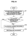
- Fig. 10 shows the specific content of the processing executed by each of the cores 18A and 18B relating to the above described first load distribution feature.
- the core 18A (18B) starts, after a command to create an internal copy pair, snapshot pair, remote copy pair, or asynchronous remote copy pair is given from the host computer 2A (2B), processing for creating a pair, as shown in Fig.10 , based on the relevant control program stored in the local memory 14A (14B), and first refers to the allocation management tables 43A (43B) for the primary and secondary volumes and acquires the identification numbers for the controllers 6A (6B) and cores 18A (18B) allocated respectively to the primary and secondary volumes (SP1).
- the core 18A (18B) checks whether or not the controllers and cores allocated to the primary and secondary volumes have to be changed (SP2). More specifically, if the pair creation command is intended for creation of an internal copy pair, the core 18A (18B) checks whether or not the core 18A (18B) allocated to the primary volume is the same as the core 18A (18B) allocated to the secondary volume. If the pair creation command is intended for creation of a snapshot pair, the core 18A (18B) checks whether or not the core 18A (18B) allocated to the primary volume is the same as the core 18A (18B) allocated to the secondary pool volume for storing the snapshot data.
- the core 18A (18B) checks whether or not that core 18A (18B) itself allocated to the primary or secondary volume is the same as the core 18A (18B) allocated to a pool volume for storing the snapshot data for the relevant logical volume.
- step SP3 If the check result is "YES,” the processing proceeds to step SP4. If the check result is "NO,” the core 18A (18B) allocated to the relevant primary (or secondary) volume is changed to the core 18A (18B) allocated to the secondary (or primary volume) (SP3).
- the core 18A (18B) changes the controller 6A (6B) and core 18A (18B) allocated to the secondary volume stored in the allocation management table 43A (43B) ( Fig. 5 ) to the controller 6A (6B) and core 18A (18B) allocated to the primary volume.
- the core 18A (18B) changes the controller 6A and core 18A (18B) allocated to the primary volume stored in the allocation management tables 43A and 43B to the controller 6A (6B) and core 18A (18B) allocated to the secondary pool volume.
- the core 18A (18B) changes the allocation of the controller 6A (6B) and core 18A (18B) allocated to the primary/secondary volume to which the core 18A (18B) itself is currently allocated, to the controller 6A (6B) and core 18A (18B) allocated to the pool volume for storing the snapshot data for the relevant logical volume.
- the core 18A (18B) executes predetermined processing for forming the pair, like controlling the relevant storage device 4A-4D to copy the data in the primary volume to the secondary volume (in the case of the internal copy pair), and terminates the pair creation processing.
- Fig. 11 is a flowchart illustrating the specific content of processing executed by each of the cores 18A and 18B relating to the above described second load dispersion feature.
- the core 18A (18B) periodically (hereinafter every 5 seconds) executes the second load dispersion processing, as shown in Fig. 11 , based on the relevant control program stored in the local memory 14A (14B).
- the core 18A (18B) starts the second load dispersion processing, and first checks whether or not the storage system 1 fulfills the prior conditions for changing the allocation so that the logical volume allocated currently to that core 18A (18B) itself is allocated to another core 18A (18B) (SP10).
- the prior conditions include: all settings of performance monitor for monitoring target items being available (i.e., settings being configured to acquire performance data for all target items); and one minute not having passed since changing the allocation of the core 18A (18B) to any logical volume, or similar.
- the former condition is desirable because all target items have to be monitored before executing the load dispersion processing, and the latter condition is necessary because, if the core 18A (18B) allocated to logical volumes is frequently changed, the performance may adversely deteriorate due to overhead generated during the processing for changing the allocation of the core 18A (18B).
- the performance monitor is processing for monitoring data I/O performance constantly executed by the microprocessor 15A (15B) in the same controller.
- step SP10 If the check result in step SP10 is NO, the core 18A (18B) terminates the second load dispersion processing. Meanwhile, if the check result in step SP10 is YES, the core 18A (18B) acquires data for the state of a load on that core 18A (18B) itself from the performance data concerning the target items acquired by the performance monitor, and converts the state of the load on that core 18A (18B) itself into a numerical value based on the above acquired data (SP11). More specifically, the core 18A (18B) executes calculation for the previous three minutes by averaging, every five seconds, the usage rate of that core 18A (18B) itself per second acquired by the performance monitor (the thus calculated value will be hereinafter referred to as the "average usage rate").
- the core 18A (18B) judges whether or not the average usage rate of that core 18A (18B) itself for the previous three minutes calculated in step SP11 fulfills predetermined first conditions for changing the allocation (SP12).
- the first conditions for changing the allocation include: eight or more of the total of thirty-six average usage rates of that core 18A (18B) itself every five seconds for the previous three minutes being not less than 80 %; the average usage rates of that core 18A (18B) itself in all one minute periods in the previous three minutes not exceeding 80 %; and the average of the average usage rates of that core 18A (18B) itself in every 5 seconds for the previous three minutes being not less than 70 %.
- the core 18A (18B) terminates the second load dispersion processing.
- the core 18A (18B) determines, for changing the allocation, a core 18A (18B) to which the logical volume allocated that core 18A (18B) itself is to be allocated next, from the other cores, which also include the cores 18B (18A) included in the microprocessor 15B (15A) in the other controller 6B (6A) (SP13-SP15).
- the core 18A (18B) first calculates the average usage rate of each of the other cores (including the other cores 18A (18B) in the same processor) every five seconds for the previous three minutes, like in step SP11 (SP13).
- the core 18A (18B) checks whether or not any of the cores 18A and 18B fulfills the predetermined second change conditions (SP14).
- the second change conditions include: no average usage rate of the core 18A (18B) every five seconds for the previous three minutes reaching 80%; and the average of the average usage rates of the core 18A (18B) every five seconds for the previous three minutes being not more than 40 %.
- the core 18A (18B) selects the core 18A (18B) that fulfills the second conditions as the destination for the allocation of the core to the relevant logical volume (SP15).
- the core 18A (18B) selects, from the logical volumes allocated to that core 18A itself, a candidate logical volume for allocated core change to the core selected in step SP15 (SP16-SP19).
- a core usage rate processing time for each logical volume/monitoring time
- this embodiment employs a method currently used by the performance monitor, i.e., calculating an approximate value for the core usage rate in each logical volume allocated to the core 18A (18B) from a proportion of the number of data inputs/outputs per second to/from each logical volume (SP16, SP17).
- Rm is the average value of the number of times data stored in the logical volume (i.e., the read target data not having been stored in the cache memory 12A (12B)) is misread per second for the past one minute: Rh is the average value of the number of read hits (i.e., the read target data having been stored in the cache memory 12A (12B)) per second for the past one minute; W is the average value of the number of times data has been written to the relevant logical volume per second for the past one minute; Th is a read hit overhead coefficient; and W is a write overhead coefficient.
- Th is set to 0.3.
- Tw is a value that depends on the RAID level formed in the storage devices 4A-4D or the pair state of the copy pair including the relevant logical volume. For example, Tw is set to 2.5 if the RAID level is "1," 5 if the RAID level is "5,” or 1 if the RAID level is "0.”
- Tw is a value obtained by multiplying the above values by 2, 1.5, or 4, respectively.
- the logical volume is a primary volume of a snapshot copy pair and the pair state of that snapshot copy pair is the "SPLIT" state (“PSUS”)
- Tw is a value obtained by multiplying the above values by 4.
- the core 18A (18B) calculates, based on the scores calculated in step SP16, the core usage rate in each logical volume from the scores for those logical volumes and the total usage rate of that core 18A (18B) itself (SP17).
- the core 18A (18B) selects, based on the core usage rate in each logical volume acquired as described above, the logical volume for allocated core change (SP18). More specifically, the core 18A (18B) chooses the logical volume that fulfills the requirement (hereinafter referred to as a "target logical volume selection requirement") that the core usage rate in the logical volume is closest to half of a difference between the core usage rate of the core that has been allocated to the logical volume and the core usage rate of the core to be the destination of the allocation change for the past one minute, so that the core usage rate of the previously allocated core becomes almost the same as the core usage rate of the core to be the allocation change destination.
- a target logical volume selection requirement the requirement that the core usage rate in the logical volume is closest to half of a difference between the core usage rate of the core that has been allocated to the logical volume and the core usage rate of the core to be the destination of the allocation change for the past one minute
- the core 18A (18B) refers to the entries corresponding to the relevant logical volume in the internal copy pair management tables 44A (44B) ( Fig. 6 ), the snapshot pair management tables 45A (45B) ( Fig. 7 ), the asynchronous remote copy pair management tables 46A (46B) ( Fig. 8 ), or the remote copy pair management tables 48A (48B) ( Fig. 4 ), checks whether or not the relevant volume forms an internal copy pair, snapshot pair, asynchronous copy pair, or remote copy pair, and also checks whether or not the logical volume forms a consistency group.
- the volumes allocated to the relevant logical volume such as the other party of the copy pair, the other logical volume(s) included in the consistency group, or other logical volume(s) mapped to a pool volume if the other party is a pool volume, are set as a logical volume group.
- the core 18A (18A) chooses the logical volume group that fulfills the target logical volume selection requirement.
- a logical volume or a logical volume group fulfills the target logical volume selection requirement, if any cross logical volume within ⁇ 3 % (a logical volume that receives read/write commands, 90 % of which comes from the controller 6B (6A) not allocated to that logical volume) exist, the non-allocated controller 6B (6A) has to be changed to the associated controller at first. Therefore, a closest cross logical volume is selected from the cross logical volumes.
- the core 18A (18B) checks whether or not the core allocated to the logical volume or all volumes in the logical volume group selected in step SP18 can be changed to the core 18A (18B) selected in step SP15 (SP19). More specifically, in this embodiment, the core allocated to a logical volume(s) cannot be changed if the usage rate of the allocation change destination core 18A (18B) after core allocation change for the logical volume or all volumes in the logical volume group becomes -10 % or more of the usage rate of the originally allocated core 18A (18B).
- the load balance remains poor even after changing the allocation.
- step SP19 the core 18A (18B) checks whether or not a fifth candidate has already been selected (SP20). If the result in step SP20 is NO, the same processing (SP18-SP20-SP18) is repeated a maximum of five times. The reason for setting the maximum number of times is that the processing time becomes long if the same processing is repeated more than five times, and with that maximum number of times the processing time can be prevented from becoming long. The maximum number of times may be a number other than five.
- the core 18A (18B) assumes that no logical volume/logical volume group to be an allocation change destination exists, executes predetermined error processing (SP21), and terminates the second load dispersion processing.
- the core 18A (18B) checks whether or not the core allocated to the selected logical volume/logical volume group can be changed to the core 18A (18B) selected in step SP15 (SP22).
- step S22 the check result in step S22 is NO in that case. Therefore, the core 18A (18B) does not change the allocation and terminates the second load dispersion processing.
- the core 18A (18B) changes the allocation. More specifically, the core 18A (18B) replaces, with the codes for the core 18A (18B) selected in step SP15 and for the controller 6A (6B) having the microprocessor 15A (15B) including that core 18A (18B), the codes stored respectively in the 'allocated core' entry 43CA and the 'allocated controller' entry 43CB corresponding to the relevant logical volume or each logical volume included in the relevant logical volume group in the allocation management tables 43A (43B) stored in the shared area 42A (42B) in the local memory 14A (14B) in the controller 6A (6B).
- the core 18A (18B) updates the allocation management table 43B (43A) stored in the shared memory 42B (42A) in the local memory 14B (14A) in the other controller 6B (6A).
- the core 18A (18B) configures settings with respect to all cores 18A and 18B in the storage controller 3 for deterring, for a fixed period of time (hereinafter referred to as "allocation change deterrent time"), the above described processing for changing the allocation of the cores to a logical volume (SP24), and terminates the second load dispersion processing.
- command issue allocation feature which is another characteristic feature provided to the controllers in the storage controller in this embodiment, will be described.
- both processing for controlling the storage device 4A-4D that functions as an initiator (i.e., issues commands) and processing for controlling the storage device 4A-4D that functions as a target (i.e., receives commands) are executed.
- issue of SCSI commands in the processing for controlling the initiator storage device 4A-4D is conducted by a controller (more specifically, a core) allocated to a primary volume, and issue of other link service-related commands is conducted by a controller (more specifically, a core) allocated to a communication port 20A used when sending those commands to the target storage device 4A-4D.
- SCSI commands can be issued via a communication port 20A allocated to a controller 6A (6B) that is not allocated to the primary logical volume, and such a cases can actually exist due to the influence of loads or failures.
- the storage controller in this embodiment has a command issue allocation feature, with which, of link service-related commands, the commands issued in relation to SCSI commands are issued by the controller 6A (6B) allocated a primary volume, and other link service-related commands (in particular, commands relating to processing executed for each port) are issued by the controller 6B (6A) allocated to the communication port 20A used when sending those commands to the target storage device 4A-4D.
- an ABTS (Abort Sequence) command used for having the target storage device 4A-4D forcefully terminate processing based on an issued SCSI command when a timeout occurs, or in other similar occasions is issued by the controller 6A (6B) allocated to a primary volume.
- issue of a PLOGI (Port Log In) command used for resetting the communication port 20A corresponding to the target storage device 4A-4D when timeout repeatedly occurs even after the ABTS command is issued, or in other similar occasions is issued by the controller 6B (6A) allocated to the communication port 20A used when sending the PLOGI command to the target.
- Fig. 12 shows the specific flow of the processing executed in the storage controller relating to the command issue allocation feature in this embodiment.
- the controller allocated to a primary volume in a copy pair that is about to be formed from now is the 1 st controller 6B, and the storage controller 3 is about to login to the initiator storage device 4A-4D via the communication port 20A allocated to the 0 th controller 6A.
- the 0 th (1 st ) controller 6A (6B) executes the processing.
- the core 18A (18B) in the 0 th (1 st ) controller 6A (6B) actually executes the processing.
- Fig. 12A shows the state where the 0 th controller 6A has just issued a PLOIN command ("PLOGI") for logging in to the initiator storage device 4A-4D via the communication port ("OA") 20A, and, as a result, logged in to a predetermined port for the relevant storage device 4A-4D.
- the 0 th controller 6A stores, after finishing the login, login information, such as an ID for the login target storage device 4A-4D, a port ID for the relevant storage device 4A-4D, and frame size, in the shared areas 42A and 42B in the local memories 14A and 14B respectively in the 0 th and 1 st controllers 6A and 6B.
- login information such as an ID for the login target storage device 4A-4D, a port ID for the relevant storage device 4A-4D, and frame size
- a login management table 50 is a table for managing addresses where the login information is stored in the shared area 14A in the 0 th controller 6A when the 0 th controller 6A has logged in to the initiator storage device(s) 4A-4D via the "OA" communication port 20A.
- the 1 st controller 6B then refers to the shared area 42B in the local memory 14B in the same controller and checks whether or not the 0 th controller 6A has logged in to the target storage device 4A-4D ("Login Check"). After checking the login based on the login information stored in the shared memory 42B, the 1 st controller 6B executes necessary processing, such as processing for translating a target ID used in the storage controller 3 into an ID that conforms to the Fibre Channel standard ("ID Conversion, etc.”).
- the 1 st controller 6B writes an SCSI command indicating that an SCSI command is about to be sent (VU (vender Unique) command) to the shared areas in the local memories respectively in the 0 th and 1 st controllers 6A and 6B.
- VU vender Unique
- the 1 st controller 6B resets, as shown in Fig. 12C , the processing for the SCSI command and writes an ABTS command for aborting the processing for that SCSI command to the shared area 42A in the local memory 14A in the 0 th controller 6A. By doing so, the ABTS command is sent by the 0 th controller 6A to the initiator storage device 4A-4D via the relevant communication port 20A. If the initiator storage device 4A-4D aborts the processing for the SCSI command, the 1 st controller 6B writes an RRQ command to the shared area 42A in the local memory 14A in the 0 th controller 6A. By doing so, the RRQ command is sent by the 0 th controller 6A to the initiator storage device 4A-4D via the relevant communication port 20A.
- the 1st controller 6B makes a request, as a last measure, for the 0 th controller to issue a PLOGI command, indicating the reset, to the initiator storage device 4A-4D, as shown in Fig. 12D .
- the 0 th controller receiving the request, issues the PLOGI command to the initiator storage device 4A-4D via the communication port 20A allocated to that 0 th controller itself.
- the core 18A (18B) in the microprocessors 15A and 15B in the controller 6A (6B) monitors the state of loads on the core 18A (18B) itself, and changes the core allocated to the logical volume originally been allocated to the core 18A (18B) to another core 18A (18B) with a smaller load. By doing so, loads on the cores 18A (18B) can be equalized. With that configuration, deterioration in data I/O processing performance due to load imbalance can be efficiently and easily prevented.
- the commands issued in relation to an SCSI command are issued by the controller 6A (6B) allocated to a primary volume, and other link service-related commands relating to processing executed for each port are issued by the controller 6B (6A) allocated to the communication port 20A used when sending the commands to the target storage device 4A-4D. Therefore, communication for exchanging commands between the controllers 6A and 6B can be made unnecessary. With that configuration, loads on the controllers 6A and 6B due to that communication can be prevented from being generated, and reduced data I/O performance due to those loads can be efficiently and easily prevented.
- the storage controller 3 includes the microprocessors 15A and 15B each having two cores (18AX, 18AY; 18BX, 18BY).
- the present invention is not limited to that configuration, and can also be used in a storage controller including microprocessors 15A and 15B each having a single core, or having three or more cores.
- the storage controller 3 includes two controllers 6A and 6B.
- the invention is not limited to that configuration, and can also be used in a storage controller having only one controller if a processor of the controller includes plural cores.
- a single core 18A (18B) includes the control unit for controlling data I/O to/from a logical volume allocated to that core 18A (18B) itself, a load monitor unit for monitoring the state of the load on each control unit, and a changer unit for changing, based on the state of the load monitored by the load monitor unit, a control unit allocated to a logical volume to another control unit to equalize loads on the control units.
- the invention is not limited to that configuration, and another core that functions as the load monitor unit for monitoring the state of a load on each core 18A (18B) may be provided separately from the cores 18A and 18B, so that the core18A (18B) can execute, based on the state of the load monitored by the load monitoring function, processing that is executed by the changer unit in the above embodiment.
- the storage controller 3 is configured as shown in Fig. 1 .
- the invention is not limited to that configuration, and can also be used in storage controllers of various configurations that provide, to a host computer, logical volumes created in a storage area provided by storage devices, and control data I/O to/from those logical volumes.
Description
- The invention relates to a storage controller and a control method for the same. More particularly, the invention is suitable for use in a storage controller in which a microprocessor that controls data I/O to/from a host computer includes plural cores (computer engines), and use in a control method for that storage controller.
- Storage controllers create, in storage areas provided by storage devices, logical volumes consisting of a logical area data is input/output to/from, and provide the created logical volumes to a host computer. Each of those controllers includes a controller for controlling data I/O to/from logical volumes according to requests from a host computer.
- Conventionally, improvement in the reliability and responsiveness of those storage controllers during processing for commands given from the host computer has been sought for. In recent years, a technique for distributing processing to plural controllers provided in a storage controller has been proposed.
-
JP-A-9-146842 JP-A-11-312058 - Those patent documents disclose storage controllers having plural identical controllers. Each controller is allocated to a logical volume, and that controller executes data I/O processing or similar for the allocated logical volume. If a controller receives, from a host computer, a command targeting a logical volume other than the logical volume allocated to that controller, the controller requests that a controller allocated to the logical volume executes processing for the command.
- Meanwhile, if plural controllers are provided in a storage controller apparatus, even if data I/O requests are issued from a host computer evenly to the controllers, the data I/O processing is executed by a controller allocated to a command target logical volume. Therefore, if the access concentrates on a certain logical volume, the load also concentrates on the controller allocated to that logical volume. The load concentration leads to reduced processing speed in the data I/O processing for the logical volume allocated to the controller.
- Also, if plural controllers are provided in a storage controller apparatus as described above and data is copied between logical volumes, different controllers may be allocated respectively to a primary volume (copy source) and a secondary volume (copy destination). If different controllers are allocated respectively to the copy source logical volume and the copy destination logical volume, those controllers have to communicate with each other during copy processing, and therefore, the loads on the controllers increase because of that communication. The increase in the loads on the controllers also leads to reduced processing speed in the data I/O processing for the logical volumes allocated to the controllers.
- To prevent the reduced processing speed in data I/O processing, it is necessary to configure settings for allocating an identical controller to both the copy source logical volume and the copy destination logical volume so that the loads do not concentrate in a specific controller. There have been many problems concerning such settings and much effort and time has gone into solving these problems.
- The present invention was made in light of the above described problem, and an object of the present invention is to provide a storage controller and control method that can effectively and easily prevent deterioration in data I/O processing performance caused by load concentration in a specific controller.
-
US patent application publication no. 2007/094357 A1 discloses a control method for a computer system including one or more host computers, one or more storage systems, and a management computer. The storage system includes a plurality of controllers connected to the host computers through a network, and one or more logical volumes for storing data used by the host computers. At least one of the logical volumes is assigned to at least one of the controllers. According to the control method, when performance information of a controller exceeds a predetermined threshold, the logical volume assigned to the controller is assigned to another controller other than the controller. Thus, access loads on a storage system used in a network environment are balanced. -
US patent no. 6675268 discloses, a storage environment or storage area network having multiple host devices and at least one storage array. The host devices access logical data volumes stored on the storage array through array controllers disposed in the storage array. Multiple host devices can request access to shared ones of the logical data volumes through multiple paths to multiple array controllers, but each logical data volume is controlled or owned by only one array controller at a time. Thus, ownership of shared logical data volumes is transferred between the array controllers as necessary on behalf of the requesting host devices. To prevent ownership transfers from occurring too often, however, ownership of the logical data volumes is made exclusive, or "sticky," for a period of time after each transfer. During the exclusive ownership period of time, the ownership cannot be transferred. After expiration of the exclusive ownership period of time, ownership of the affected logical data volume is transferred if the transfer does not cause another host device to lose access to the same logical data volume, unless priorities between competing host devices permit one host device to take access away from the other host device. - The present invention provides a storage controller as set out in
claim 1 and a method for controlling a storage controller as set out in claim 10. - An aspect of the disclosure provides a storage controller for creating, in a storage area provided by a storage device, plural logical volumes consisting of a logical area data is input/output to/from, providing the created logical volumes to a host computer, and controlling data I/O to/from the logical volumes according to a request from the host computer, the storage controller including: plural control units, each control unit for controlling data I/O to/from a logical volume allocated to that control unit; a load monitor unit for monitoring the state of loads on each control unit; and a changer unit for changing the control unit allocated to logical volumes to another control unit to equalize the loads on the controllers.
- Another aspect of the disclosure provides a control method for a storage control device for creating, in a storage area provided by a storage device, plural logical volumes consisting of a logical area data is input/output to/from, providing the created logical volumes to a host computer, and controlling data I/O to/from the logical volume according to a request from the host computer, the storage control device having plural control units, each control unit for controlling data I/O to/from a logical volume allocated to that control unit (itself), the method including: a first step of monitoring the state of loads on each control unit; and a second step of changing the control unit allocated to the logical volumes to another control unit to equalize the loads on the control units.
- The above described aspects of the invention can realize a storage controller and control method that can equalize loads on the control units and efficiently and easily prevent deterioration in data I/O processing performance caused by load concentration in specific control units.
-
-
Fig. 1 is a block diagram showing the overall configuration for a storage system according to an embodiment. -
Fig. 2 is a conceptual diagram illustrating a queue structure in a logical memory in a storage controller. -
Fig. 3A is a table showing an example of memory space recognized by 0th and 1st microprocessors; andFig. 3B is a table showing an example of memory space recognized by 0th and 1st host communication protocol chips. -
Fig. 4A is a conceptual diagram showing the memory structure of a 0th local memory; andFig. 4B is a conceptual diagram showing the memory structure of a 1st local memory. -
Fig. 5 is a conceptual diagram illustrating an allocation management table. -
Fig. 6 is a conceptual diagram illustrating an internal copy pair management table. -
Fig. 7 is a conceptual diagram illustrating a snapshot copy pair management table. -
Fig. 8 is a conceptual diagram illustrating an asynchronous remote copy pair management table. -
Fig. 9 is a conceptual diagram illustrating a pool management table. -
Fig. 10 is a flowchart illustrating first processing for distributing loads. -
Fig. 11 is a flowchart illustrating second processing for distributing loads. -
Fig. 12A-12D are conceptual diagrams illustrating a command issue allocation feature. - An embodiment of the invention will be described below with reference to the drawings.
-
Fig. 1 shows astorage system 1 according to this embodiment. In thestorage system 1,host computers storage controller 3, tostorage devices 4A-4D. - The
host computers host computers storage controller 3, with which each of thehost computers storage controller 3. - The
storage controller 3 includes 0th and 1stcontrollers different host computers inter-controller connection 5 that connects thecontrollers - The
inter-controller connection 5 may be a bus that conforms to the PCI (Peripheral Component Interconnect) -Express standard, which uses up to eight lanes and permits rapid data communication at the data transfer amount of 2 G bit/sec per lane. Exchange of all data and commands between the 0th and 1stcontrollers inter-controller connection 5. - The
controller 6A (6B) controls data I/O to/from each of thestorage devices 4A-4D according to requests from thehost computer 2A (2B) connected to thecontroller 6A (6B). Thecontrollers host communication controllers data transfer controllers cache memories bridges local memories microprocessors device communication controllers side switches - The
host communication controllers host computers communication ports communication protocol chips - The
communication ports controllers host computers - The host
communication protocol chip 21A (21B) controls communication with thehost computer 2A (2B). A host communication protocol chip that conforms to the communication protocol used during communication with thehost computer 2A (2B) is used for hostcommunication protocol chips 21A and 21 B. For example, the hostcommunication protocol chips host computers - Each of the host
communication protocol chips communication protocol chips microprocessor 15A in the 0thcontroller 6A and themicroprocessor 15B in the 1stcontroller 6B. - The
data transfer controllers controllers controller 6A and those in the 1stcontroller 6B, and copies, according to an order from the microprocessor in the same controller, write data sent from thehost computer cache memories microprocessor 15A (15B) writes, after storing data in thecache memory 12A (12B) in the same controller, that data also to thecache memory - When the
data transfer controller 11A (11B) updates information in sharedarea 42A (42B) (Fig. 4 ), which will be described later, in thelocal memory 14A (14B) in the same controller, thedata transfer controller 11A (11B) also updates the information in the sharedarea 42B (42A) so that the information stored in the sharedareas - The
bridges microprocessors local memories 14A and14B to thedata transfer controllers bridges 13A (13B) extract only relevant data from data exchanged via buses connecting thehost communication controller 10A (10B), thedata transfer controller 11A (11B), the storagedevice communication controller 16A (16B), and thecache memory 12A (12B), and transfer the extracted data to themicroprocessor 15A (15B) or thelocal memory 14A (14B). - The
microprocessors 15A (15B) govern the entire operation control in thecontroller 6A (6B) themicroprocessors 15A (15B) belong to. Themicroprocessor 15A (15B) executes, according to a write/read command held in thelocal memory microprocessor 15A (15B) (hereinafter referred to as an "allocated logical volume"), as will be described later. - The
microprocessors cores 18A (18AX, 18AY) andcores 18B (18BX and 18BY). In the example shown inFig. 1 , themicroprocessor 15A includes an X core 18AX and a Y core 18YA, and themicroprocessor 15B includes an X core 18BX and a Y core 18BY. Thecore 18A (18B) executes plural software threads in parallel in an appropriate software environment. At least one logical volume in the logical volumes allocated to each microprocessor is allocated to each of thecores core 18A (18B) handles control of data I/O processing for the logical volumes allocated to thatcore 18A (18B) itself and other relevant processing. - The allocation of the logical volumes to the
cores cores storage controller 3 and thehost computers storage controller 3 and eachstorage device 4A-4B. - The
local memories host computer microprocessor 15A (15B) processes the read/write commands stored in thelocal memory 14A (14B) in the order the commands are stored in thelocal memory 14A (14B). Microprograms for controlling themicroprocessors local memories same controllers - Each of the
local memories host computers Fig. 2. Fig. 2 shows the scheme of the queue structure in thecontroller 6A. The 1stcontroller 6B, theinter-controller connection 5 connected to the 1stcontroller 6B, and thestorage devices 4A-4D are omitted inFig. 2 . The following explanation of thelocal memory 6A applies to the otherlocal memory 6B. - The queue structure includes
reception queues 200 for storing commands from thehost computer 2A received by the hostcommunication protocol chip 21A in thehost communication controller 10A, andcommand queues 202 for storing commands to be processed by the X core 18AX or Y core 18AY in themicroprocessor 15A. - Each
reception queue 200 corresponds to one of thecommunication ports 20A in thehost communication controller 10A, and a command issued by thehost computer 2A to acommunication port 20A is stored in thereception queue 200 corresponding to thatcommunication port 20A. For example, inFig. 2 , a command issued by thehost computer 2A to the communication port "A" 20A is stored in the reception queue "a" 200, a command issued by thehost computer 2A to the communication port "B" 20A is stored in the reception queue "b" 200, a command issued by thehost computer 2A to the communication port "C" 20A is stored in the reception queue "c" 200, and a command issued by thehost computer 2A to the communication port "D" 20A is stored in the reception queue "d" 200. The commands are stored in thereception queues 200 as described above by the hostcommunication protocol chip 21A. - The command stored in each
reception queue 200 is processed by thecore 18A that has been set as allocated to thecommunication port 20A corresponding to thatreception queue 200. In other words, whichcore 18A processes a command stored in eachreception queue 200 is determined in advance. For example, inFig. 2 , commands stored in the reception queues "A" and "B" 200 are processed by the X core 18AX, and commands stored in the reception queues "C" and "D" 200 are processed by the Y core 18 AY. The X core 18AX and Y core 18AY each sequentially read commands from thereception queues 200 corresponding to thecommunication ports 20A allocated respectively to those X and Y cores, analyze the commands, e.g., check which logical volume LU the command was issued to or whichcore 18A should execute the command, and store the commands in the relevant command queue(s) 202. -
Plural command queues 202 are provided in a single logical volume LU. A command for a logical volume LU is stored in acommand queue 202 corresponding to that logical volume LU. In the example shown inFig. 2 , command queues "A" and "B" 202 are provided in the logical volume LU with LUN "0," and commands for that logical volume LU are stored in command queue "A" or "B." The command queues "C" and "D" are provided for the logical volume LU with LUN "1," and the commands for that logical volume LU are stored in command queue "C" or "D." The X core 18AX handles processing for read/write commands for the logical volume LU with LUN "0," and the Y core 18AY handles processing for commands to the logical volume LU with LUN "1." - Which
core 18A moves commands to eachcommand queue 202, and whichcore 18A is allocated for the execution of commands stored in eachcommand queue 202 are decided according to a characteristics table 204 stored in thelocal memory 14A. - As described above, which
core 18A executes command processing is determined for each logical volume LU in this embodiment. Therefore, no contention occurs between the X core 18AX and Y core 18AY for processing for a single logical volume LU, and the X core 18AX and Y core 18AY can independently process I/O access to different logical volumes LU. With that configuration, for example, the situation where contention occurs between twocores 18A for processing for a logical volume LU and thecore 18A with the smaller load has to wait for the other core's processing to finish can be avoided. Accordingly, bothcontrollers host computer - Referring back to
Fig. 1 , thecache memory 12A (12B) is used mainly for temporarily storing data transferred between thehost computer 2A (2B) and eachstorage device 4A-4D, or between the 0th and 1stcontrollers - The storage
device communication controllers communication protocol chips storage device 4A-4D. The storage devicecommunication protocol chips storage devices 4A-4D, or SAS protocol chips if SAS hard disk drives are used as thestorage devices 4A-4D. If SATA hard disk drives are used as thestorage devices 4A-4D, FC protocol chips or SAS protocol chips are used as the storage devicecommunication protocol chips storage devices 4A-4D, the storagedevice communication controllers storage devices 4A-4D via a SATA protocol translation chip. - The storage device-
side switches storage devices 4A-4D for a communication target. Alternatively, thestorage devices 4A-4D may be connected to thecontrollers side switches - Examples of the
storage devices 4A-4D include a disk array of hard disk drives, more specifically FC hard disk drives, SAS hard disk drives, or SATA hard disk drives. Plural logical volumes, which are logical storage areas data is written/read to/from, can be set in the storage area provided by the hard disk drives. - Reliability and responsiveness of the logical volumes can be enhanced by utilizing RAID technique for the
storage devices 4A-4D. More specifically, various RAID levels, such as "RAID 0," "RAID 1," "RAID 3," "RAID 5," "RAID 6," or "RAID 0+1," can be set for each logical volume. - Storage devices used in the
storage devices 4A-4D may also be semiconductor memory such as flash memory, or optical disk devices, instead of hard disk drives. If flash memory is used, any type of flash memory, e.g., a first, inexpensive type with a relatively low writing speed and small restricted write number, or a second, expensive type with a higher writing speed and a larger restricted write number than the first type. Alternatively, thestorage devices 4A-4D may include both flash memory of the above described first or second type and hard disk drives at the same time. - Next, command processing executed in the
storage controller 3 in thestorage system 1 will be described. In thestorage system 1, both the memory areas in the 0th and 1stcontrollers controllers controller 6A (6B) can also directly access the memory area in theother controller 6B (6A). - The core 18AX (18BX) in the
microprocessor 15A (15B) in the 0th (1st)controller 6A (6B) transfers, after a write/read command targeting a logical volume allocated to theother controller 6B (6A) is sent from thehost computer 2A (2B), the read/write command to theother controller 6B (6A) by writing the command to theother controller 6B (6A)'slocal memory 14B (14A). - As described above, when a write/read command to be executed by the
other controller 6B (6A) is sent from the host computer to thecontroller 6A (6B) in thestorage system 1, the command is transferred by directly writing it to thelocal memory 16B (16A) in theother controller 6B (6A). Therefore, the 0th and 1stcontrollers -
Fig. 3A shows a memory map for the memory space in thecontrollers microprocessors Fig. 3B shows a memory map for the memory space recognized respectively by the 0th and 1st hostcommunication protocol chips - Referring to
Fig. 3A , the memory space recognized by the 0thmicroprocessor 15A is memory space consisting of a storage area provided by memory or register stored in thefield 30B for "CTL0 Memory Map (CTL0 processor)," i.e., an area within the range of the addresses stored in the "ADR" field, and the memory space recognized by the 1stmicroprocessor 15B is memory space consisting of a storage area provided by the memory or register stored in thefield 30C for "CTL1 Memory Map (CTL 1 processor)," i.e., an area within the range of the addresses stored in the "ADR"field 30A. - Referring also to
Fig. 3B , the memory space recognized by the 0th hostcommunication protocol chip 10A is memory space consisting of a storage area provided by the memory or register stored in thefield 31 B for "CTL0 Memory Map (CTL0 host communication protocol chip)," i.e., an area within the range of the addresses stored in the "ADR"field 31A, and the memory space recognized by the 1st hostcommunication protocol chip 10B is memory space consisting of a storage area provided by the memory stored in thefield 31C for "CTL1 Memory Map (CTL1 host communication protocol chip)," i.e., an area within the range of the addresses stored in the "ADR" field 31." - In the data stored in the memory maps shown in
Figs. 3A and 3B , the addresses in thelocal memory 14 A (14B) (0x0_00000000-0x0_7FFFFFFF) and the addresses in thebridge 13A (13B) (0x0_80000000_0x0_FFFFFFFF) in thesame controller 6A (6B) are stored in advance as first address information in flash memory (not shown) connected to themicroprocessor 15A (15B). Addresses other than the above inFig. 3A are stored in advance as second information in a register (not shown) provided in thedata transfer controllers 11A (11B) in thesame controller 6A (6B). - The
microprocessor 15A (15B) and the hostcommunication protocol chip 21A (21 B) in 0th (1st)controller 6A (6B) can recognize the memory space as shown respectively in the memory maps shown inFigs. 3A and 3B based on the first and second address information stored in the flash memory and register, and can access, based on the recognized memory space, not only thelocal memory 14A (14B) and thecache memory 12A (12B) in thesame controller 6A (6B), but also those in the other controllers. -
Figs. 4A and 4B show the memory structure in thelocal memories controllers Figs. 4A and 4B , thecontrollers local memories storage areas storage areas areas storage areas storage areas - The command (received by the same controller)
storage areas host communication controller 10A (10B) in the same controller are stored in the control information storage area 40AXA (40 BXA) or 40AYA (4BYA). - The command (received by the other controller)
storage areas host communication controller 10B (10A) in theother controller 6B (6A) are stored in the control information storage area 41AXA (41BXA) or 41 BXA (41 BYA). - The command (received by the other controller)
storage areas controller 6A (6B) is allocated for execution of processing for a logical volume that has been previously allocated to theother controller 6B (6A), the content of the processing to be executed after a received command is analyzed in theother controller 6B (6A) and stored in the executed processing storage area 41AXB (41BXB) or 41AYB (41 BYB). That processing is executed when themicroprocessor 15B (15A) in theother controller 6B (6A) is down due to a failure, or in similar situations. - The shared areas 32A and 32B respectively store allocation management tables 43A and 43B, internal copy pair management tables 44A and 44B, snapshot pair management tables 45A and 45B, asynchronous remote copy pair management tables 46A and 46B, remote copy pair management tables 47A and 47B, and pool management tables 48A and 48B. Those tables will be described later in detail.
- Next, a feature for dispersing loads in the
storage controller 3 will be described. In this embodiment, thestorage controller 3 has a first feature for dispersing loads by changing, to asingle core single core single core single core - In this embodiment, the
storage controller 3 also has a second feature for dispersing loads by monitoring the states of the loads on thecores microprocessors controllers core 18A (18B) with a higher load allocated to a logical volume to anothercore 18A (18B) with a lower load in order to equalize the loads on thecores storage controller 3 also changes, to asingle core single core - As means for realizing the first and second load distribution features, the allocation management tables 43A and 43B, the internal copy pair management tables 44A and 44B, the snapshot pair management tables 45A and 45B, the asynchronous remote copy pair management tables 46A and 46B, the remote copy pair management tables 47A and 47B, and the pool management tables 48A and 48B are respectively stored in the shared
areas local memories controllers storage controller 3. - The allocation management tables 43A and 43B are tables for managing the
controller 6A (6A) and core allocated to each logical volume created in thestorage devices 4A-4D, and are prepared every time a logical volume is created. Eachcore 18A (18B) knows from the allocation management table 43A (43B) whether a logical volume is allocated to itself or not. - As shown in
Fig. 5 , the allocation management table 43A (43B) includes an 'allocated controller' entry 43CA and an 'allocated core' entry 43CB. The 'allocated controller' entry 43CA stores the identification number provided for thecontroller 6A (6B) allocated for the execution of processing based on commands such as read/write commands (command processing) for the relevant logical volume (hereinafter referred to as an "allocated controller"). The 'allocated core' entry 43CB stores the identification number provided for thecore 18A (18B) allocated to the relevant logical volume included in themicroprocessor 15A (15B) in the above allocated controller. - The internal copy pair management tables 44A and 44B are tables for managing pairs of logical volumes between which internal copy is executed (hereinafter referred to as "internal copy pair(s)"), and are prepared for each logical volume. The "internal copy" means data copy executed between logical volumes formed in the
same storage device 4A-4D. As shown inFig. 6 , the internal copy pair management tables 44A and 44B include a 'pair state' entry 44CA, 'pair attribute' entry 44CB, 'paired volume's LUN' entry 44CC, 'mirror number' entry 44CD, 'copy speed' entry 44CE, 'group type' entry 44CF, 'group ID' entry 44CG, and 'secondary LUN' entry CH. - The 'pair state' entry 44CA stores a code indicating the pair state in a copy pair including the relevant logical volume. The pair states include a state where the internal copy pair including the relevant logical volume has not been defined ("SMPL"), a state where initial copy or resynchronizing copy is being executed ("COPY"), a state where data content in a primary volume matches that in a secondary volume in an internal copy pair ("PAIR"), and a state where data content in a primary volume is not reflected in a secondary volume in an internal copy pair ("PSUS").
- The 'pair attribute' entry 44CB stores a code indicating the pair attribute (primary/secondary) of the relevant logical volume. The 'paired volume's LUN' entry 44CC stores the logical volume number of the primary volume if the relevant logical volume is set as a secondary volume in an internal copy pair. The 'paired volume's LUN' entry 44CC cannot be referred to if the relevant logical volume is set as a primary volume.
- In this embodiment, up to eight secondary volumes can be set for an internal copy pair, and the order of those secondary volumes is stored in the 'mirror number' entry 44CD. The 'copy speed' entry 44CE stores a code indicating the speed set as a copy speed used during initial copy or resynchronizing copy in the internal copy.
- Also, in this embodiment, several internal copy pairs can be set as a single group. The 'group type' entry 44CF stores a code indicating whether the group setting is valid/invalid. If the relevant logical volume belongs to any of the groups, an ID provided for that group is stored in the 'group ID' entry 44CG.
- Values stored in the 'mirror number' entry 44CD, 'copy speed' entry 44CE, 'group type' entry 44CF, and 'group ID' entry 44CG are valid only when the relevant logical volume is set as a secondary volume in an internal copy pair.
- If the relevant logical volume is set as a primary volume, the 'secondary LUN' entry 44CH stores the logical volume number for the secondary volume. As described above, in this embodiment up to eight secondary volumes can be set for an internal copy pair, and the 'secondary LUN' entry 44CH stores the logical volume number for the logical volumes set as the secondary volumes.
- Meanwhile, snapshot pair management tables 45A and 45B are tables for managing pairs of logical volumes and pool volumes for storing snapshot data (pre-update data) for those logical volumes (hereinafter referred to as "snapshot pair(s)"), and are prepared for each logical volume. As shown in
Fig. 7 , the snapshot pair management tables 45A and 45B include a 'pair state' entry 45CA, 'pair attribute' entry 45CB, 'paired volume's LUN' entry 45CC, 'secondary LU' entry number' 45CD, 'mirror number' entry 45CF, 'group ID type' entry 45CG, 'group ID' entry 45CH, and 'pool volume number' entry 45Cl. - The 'pair state' entry 45CA stores a code indicating the pair state of a snapshot pair including the relevant logical volume. The 'pair attribute' entry 45CB stores a code indicating the pair attribute (primary/secondary) of the relevant logical volume if the relevant logical volume and another logical volume are set as a snapshot pair.
- The 'paired volume's LUN' entry 45CC stores, if the relevant logical volume is set as a secondary volume (i.e., a pool volume) of a snapshot pair, the logical volume number for its primary volume. The 'paired volume's LUN' entry 45 CC cannot be referred to if the relevant logical volume is a primary volume of a snapshot pair.
- The 'secondary LU number' entry 45CD stores the number of secondary volumes (i.e., pool volumes) with which the relevant logical volume forms a snapshot pair. In this embodiment, up to thirty-two logical volumes can be set as secondary volumes of a snapshot pair. The 'secondary LUN' entry 45CE stores the logical volume number for secondary volume(s) with which the relevant logical volume forms a snapshot pair. The "secondary LUN" entry 45CE can be referred to only when the pair attribute of the relevant logical volume is "primary."
- The 'mirror number' entry 45CF stores, if the relevant logical volume is a secondary volume of the snapshot pair, the number indicating its position of the secondary volumes. In this embodiment, plural snapshot pairs can be set as a single group, and the 'group ID type' entry 45CG stores a code indicating whether the group setting is valid/invalid. If the relevant logical volume belongs to any such group, the 'group ID' entry 45CH stores the ID provided for that group.
- The 'pool number' entry 45CI stores, if the relevant logical volume is a primary volume of a snapshot pair, the pool volume number that is an identification number for the secondary volume (pool volume). This 'pool number' entry 45Cl can be referred to only when the relevant logical volume is a primary volume of a snapshot pair.
- The asynchronous remote copy pair management tables 46A and 46B are tables for managing pairs of logical volumes between which asynchronous remote copy is conducted (hereinafter referred to as "asynchronous remote copy pairs"), and are prepared for each logical volume. "Asynchronous remote copy" is a method for copying data between primary and secondary volumes asynchronously with data write from the host computer to the primary volume. In that method, the primary and
secondary storage devices 4A-4D regularly create snapshots of the respective primary and secondary volumes. - The asynchronous remote copy pair management tables 46A and 46B respectively include 'pair state' entry 46CA, 'pair attribute' entry 46CB, 'consistency group ID' entry 46CC, 'paired volume's LUN' entry 46CD, 'copy speed' entry 46CE, and 'pool number' entry 46CF.
- The 'pair state' entry 46CA stores a code indicating the pair state of an asynchronous remote copy pair including the relevant logical volume. The 'pair attribute' entry 46CB stores, if the relevant logical volume and another logical volume are set as an asynchronous remote copy pair, a code indicating the pair attribute of the relevant logical volume (primary/secondary).
- The 'consistency group ID' entry 46CC stores an identification number (consistency group number) provided for a consistency group including the relevant logical volume. The "consistency group" is a group of plural logical volumes each storing associated data, such as a group of a logical volume storing content data for a database, a logical volume storing search data for the database, and a logical volume storing log data for the database.
- The 'paired LUN' entry 46CD stores, if the relevant logical volume is set as a secondary volume of an asynchronous remote copy pair, the logical volume number for the primary volume. The 'copy speed' entry 46CE stores a code indicating the speed set as the copy speed used during initial copy or resynchronizing copy in the asynchronous remote copy. The 'pool volume number' entry 46CR stores the pool volume number for a pool volume for storing the data of a snapshot of the relevant logical volume.
- The remote copy pair management tables 47A and 47B are tables for managing pairs of logical volumes between which remote copy is executed (hereinafter referred to as "remote copy pair(s)"), and are prepared for each logical volume. "Remote copy" is a method for copying data written to a primary logical volume set in a
primary storage device 4A-4D to a secondary volume set in asecondary storage device 4A-4D synchronously with data write from the host computer to the primary volume. In that method, the primary andsecondary storage devices 4A-4D regularly create snapshots of the respective primary and secondary volumes. - The remote copy pair management tables 47A and 47B have the same configuration as the asynchronous remote copy pair management tables 46A and 46B, so their explanation has been omitted.
- The pool management tables 48A and 48B are tables for managing logical volumes that form a pool volume, and are prepared for each logical volume belonging to a pool volume. As shown in
Fig. 9 , the pool management tables 48A and 48B respectively include a 'logical volume number' entry 48CA, 'head pool flag' entry 48CB, and 'affiliated pool volume number' entry 48CC. - The 'logical volume number' entry 48CA stores the logical volume number for each of the relevant logical volumes that belong to a pool volume. The 'head pool flag' entry 48CB stores a code indicating whether or not the relevant logical volume is a volume the head address of the pool volume is allocated to. The 'affiliated pool volume number' entry 48CC stores the pool number for the pool volume the relevant logical volume belongs to.
-
Fig. 10 shows the specific content of the processing executed by each of thecores - The
core 18A (18B) starts, after a command to create an internal copy pair, snapshot pair, remote copy pair, or asynchronous remote copy pair is given from thehost computer 2A (2B), processing for creating a pair, as shown inFig.10 , based on the relevant control program stored in thelocal memory 14A (14B), and first refers to the allocation management tables 43A (43B) for the primary and secondary volumes and acquires the identification numbers for thecontrollers 6A (6B) andcores 18A (18B) allocated respectively to the primary and secondary volumes (SP1). - Subsequently, the
core 18A (18B) checks whether or not the controllers and cores allocated to the primary and secondary volumes have to be changed (SP2). More specifically, if the pair creation command is intended for creation of an internal copy pair, thecore 18A (18B) checks whether or not thecore 18A (18B) allocated to the primary volume is the same as thecore 18A (18B) allocated to the secondary volume. If the pair creation command is intended for creation of a snapshot pair, thecore 18A (18B) checks whether or not thecore 18A (18B) allocated to the primary volume is the same as thecore 18A (18B) allocated to the secondary pool volume for storing the snapshot data. If the pair creation command is intended for creation of an asynchronous remote copy pair or a remote copy pair, thecore 18A (18B) checks whether or not thatcore 18A (18B) itself allocated to the primary or secondary volume is the same as thecore 18A (18B) allocated to a pool volume for storing the snapshot data for the relevant logical volume. - If the check result is "YES," the processing proceeds to step SP4. If the check result is "NO," the
core 18A (18B) allocated to the relevant primary (or secondary) volume is changed to thecore 18A (18B) allocated to the secondary (or primary volume) (SP3). - More specifically, if the pair creation command is intended for an internal copy pair, the
core 18A (18B) changes thecontroller 6A (6B) andcore 18A (18B) allocated to the secondary volume stored in the allocation management table 43A (43B) (Fig. 5 ) to thecontroller 6A (6B) andcore 18A (18B) allocated to the primary volume. If the pair creation command is intended for creation of a snapshot pair, thecore 18A (18B) changes thecontroller 6A andcore 18A (18B) allocated to the primary volume stored in the allocation management tables 43A and 43B to thecontroller 6A (6B) andcore 18A (18B) allocated to the secondary pool volume. If the pair creation command is intended for creation of an asynchronous remote copy pair or remote copy pair, thecore 18A (18B) changes the allocation of thecontroller 6A (6B) andcore 18A (18B) allocated to the primary/secondary volume to which thecore 18A (18B) itself is currently allocated, to thecontroller 6A (6B) andcore 18A (18B) allocated to the pool volume for storing the snapshot data for the relevant logical volume. - After that, the
core 18A (18B) executes predetermined processing for forming the pair, like controlling therelevant storage device 4A-4D to copy the data in the primary volume to the secondary volume (in the case of the internal copy pair), and terminates the pair creation processing. -
Fig. 11 is a flowchart illustrating the specific content of processing executed by each of thecores core 18A (18B) periodically (hereinafter every 5 seconds) executes the second load dispersion processing, as shown inFig. 11 , based on the relevant control program stored in thelocal memory 14A (14B). - In practice, the
core 18A (18B) starts the second load dispersion processing, and first checks whether or not thestorage system 1 fulfills the prior conditions for changing the allocation so that the logical volume allocated currently to thatcore 18A (18B) itself is allocated to anothercore 18A (18B) (SP10). - In this embodiment, the prior conditions include: all settings of performance monitor for monitoring target items being available (i.e., settings being configured to acquire performance data for all target items); and one minute not having passed since changing the allocation of the
core 18A (18B) to any logical volume, or similar. The former condition is desirable because all target items have to be monitored before executing the load dispersion processing, and the latter condition is necessary because, if thecore 18A (18B) allocated to logical volumes is frequently changed, the performance may adversely deteriorate due to overhead generated during the processing for changing the allocation of thecore 18A (18B). The performance monitor is processing for monitoring data I/O performance constantly executed by themicroprocessor 15A (15B) in the same controller. The performance monitor target items include the number of data inputs/outputs per second to/from each logical volume allocated to thecore 18A (18B) in themicroprocessor 15A (15B) in the same controller (IOPS), and the usage rate of each core 18A (18B) in themicroprocessor 15A (15B) in the same controller per second (= processing time/monitor time). - If the check result in step SP10 is NO, the
core 18A (18B) terminates the second load dispersion processing. Meanwhile, if the check result in step SP10 is YES, thecore 18A (18B) acquires data for the state of a load on thatcore 18A (18B) itself from the performance data concerning the target items acquired by the performance monitor, and converts the state of the load on thatcore 18A (18B) itself into a numerical value based on the above acquired data (SP11). More specifically, thecore 18A (18B) executes calculation for the previous three minutes by averaging, every five seconds, the usage rate of thatcore 18A (18B) itself per second acquired by the performance monitor (the thus calculated value will be hereinafter referred to as the "average usage rate"). - After that, the
core 18A (18B) judges whether or not the average usage rate of thatcore 18A (18B) itself for the previous three minutes calculated in step SP11 fulfills predetermined first conditions for changing the allocation (SP12). In this embodiment, the first conditions for changing the allocation include: eight or more of the total of thirty-six average usage rates of thatcore 18A (18B) itself every five seconds for the previous three minutes being not less than 80 %; the average usage rates of thatcore 18A (18B) itself in all one minute periods in the previous three minutes not exceeding 80 %; and the average of the average usage rates of thatcore 18A (18B) itself in every 5 seconds for the previous three minutes being not less than 70 %. - If the average usage rates of the
core 18A (18B) every five seconds for the previous three minutes fulfill none of the first conditions for changing the allocation, thecore 18A (18B) terminates the second load dispersion processing. - Meanwhile, if the average usage rates of the
core 18A (18B) every five seconds for the previous three minutes fulfill at least one of the first conditions for changing the allocation, thecore 18A (18B) determines, for changing the allocation, acore 18A (18B) to which the logical volume allocated thatcore 18A (18B) itself is to be allocated next, from the other cores, which also include thecores 18B (18A) included in themicroprocessor 15B (15A) in theother controller 6B (6A) (SP13-SP15). - More specifically, the
core 18A (18B) first calculates the average usage rate of each of the other cores (including theother cores 18A (18B) in the same processor) every five seconds for the previous three minutes, like in step SP11 (SP13). - Subsequently, the
core 18A (18B) checks whether or not any of thecores core 18A (18B) every five seconds for the previous three minutes reaching 80%; and the average of the average usage rates of thecore 18A (18B) every five seconds for the previous three minutes being not more than 40 %. - If any of the
other cores core 18A (18B) selects thecore 18A (18B) that fulfills the second conditions as the destination for the allocation of the core to the relevant logical volume (SP15). - If several
other cores 18A (18B) fulfill all of the second conditions for changing the allocation in step SP14, priority is given to theother cores 18A (18B) in thesame controller 6A (6B) when setting the destination for the allocation change, because overhead generated due to the allocation change between thecores 18A (18B) in the same controller is smaller than that generated due to the allocation change between cores in different controllers. Meanwhile, if no core fulfills all of the second conditions for changing the allocation, thecore 18A (18B) chooses, as the destination for the allocation change, thecore 18B (18A) with the lowest average usage rates every five seconds in the previous three minutes from thecores 18B (18A) in themicroprocessor 15B (15A) in theother controller 6B (6A). That is because more loads can be dispersed by setting thecore 18B (18A) with the lowest average usage rates as the destination of the allocation change. - Subsequently, the
core 18A (18B) selects, from the logical volumes allocated to thatcore 18A itself, a candidate logical volume for allocated core change to the core selected in step SP15 (SP16-SP19). - The above candidate may conceivably be selected by using a method calculating the usage rate of the
core 18A (18B) for each of the logical volumes allocated to therelevant core 18A (18B) (= (processing time for each logical volume/monitoring time)) (hereinafter referred to as a "core usage rate") and choosing the logical volume with the largest core usage rate. However, acquiring a core usage rate in each logical volume is difficult in the present circumstances. Also, additional processing for acquiring information becomes necessary for the above method in many cases, resulting in reduced performance. - Therefore, for selecting the candidate logical volume, this embodiment employs a method currently used by the performance monitor, i.e., calculating an approximate value for the core usage rate in each logical volume allocated to the
core 18A (18B) from a proportion of the number of data inputs/outputs per second to/from each logical volume (SP16, SP17). - More specifically, the
core 18A (18B) converts, based on the following formula, the core usage rate in each logical volume allocated to thatcore 18A (18B) itself into a score (SP16):
- In formula (1), Rm is the average value of the number of times data stored in the logical volume (i.e., the read target data not having been stored in the
cache memory 12A (12B)) is misread per second for the past one minute: Rh is the average value of the number of read hits (i.e., the read target data having been stored in thecache memory 12A (12B)) per second for the past one minute; W is the average value of the number of times data has been written to the relevant logical volume per second for the past one minute; Th is a read hit overhead coefficient; and W is a write overhead coefficient. - In this embodiment, Th is set to 0.3. Tw is a value that depends on the RAID level formed in the
storage devices 4A-4D or the pair state of the copy pair including the relevant logical volume. For example, Tw is set to 2.5 if the RAID level is "1," 5 if the RAID level is "5," or 1 if the RAID level is "0." However, if the relevant logical volume is a primary volume of an internal copy pair, remote copy pair, or asynchronous remote copy pair, and if the pair state of that internal copy pair, remote copy pair, or asynchronous remote copy pair is the state where the data in the primary volume matches the data in the secondary volume ("PAIR"), Tw is a value obtained by multiplying the above values by 2, 1.5, or 4, respectively. Meanwhile, if the logical volume is a primary volume of a snapshot copy pair and the pair state of that snapshot copy pair is the "SPLIT" state ("PSUS"), Tw is a value obtained by multiplying the above values by 4. - Subsequently, the
core 18A (18B) calculates, based on the scores calculated in step SP16, the core usage rate in each logical volume from the scores for those logical volumes and the total usage rate of thatcore 18A (18B) itself (SP17). - After that, the
core 18A (18B) selects, based on the core usage rate in each logical volume acquired as described above, the logical volume for allocated core change (SP18). More specifically, thecore 18A (18B) chooses the logical volume that fulfills the requirement (hereinafter referred to as a "target logical volume selection requirement") that the core usage rate in the logical volume is closest to half of a difference between the core usage rate of the core that has been allocated to the logical volume and the core usage rate of the core to be the destination of the allocation change for the past one minute, so that the core usage rate of the previously allocated core becomes almost the same as the core usage rate of the core to be the allocation change destination. - For the above selection, the
core 18A (18B) refers to the entries corresponding to the relevant logical volume in the internal copy pair management tables 44A (44B) (Fig. 6 ), the snapshot pair management tables 45A (45B) (Fig. 7 ), the asynchronous remote copy pair management tables 46A (46B) (Fig. 8 ), or the remote copy pair management tables 48A (48B) (Fig. 4 ), checks whether or not the relevant volume forms an internal copy pair, snapshot pair, asynchronous copy pair, or remote copy pair, and also checks whether or not the logical volume forms a consistency group. - If the relevant logical volume forms any of those copy pairs or forms a consistency group, the volumes allocated to the relevant logical volume, such as the other party of the copy pair, the other logical volume(s) included in the consistency group, or other logical volume(s) mapped to a pool volume if the other party is a pool volume, are set as a logical volume group. The
core 18A (18A) chooses the logical volume group that fulfills the target logical volume selection requirement. - However, even if a logical volume or a logical volume group fulfills the target logical volume selection requirement, if any cross logical volume within ± 3 % (a logical volume that receives read/write commands, 90 % of which comes from the
controller 6B (6A) not allocated to that logical volume) exist, thenon-allocated controller 6B (6A) has to be changed to the associated controller at first. Therefore, a closest cross logical volume is selected from the cross logical volumes. - After that, the
core 18A (18B) checks whether or not the core allocated to the logical volume or all volumes in the logical volume group selected in step SP18 can be changed to thecore 18A (18B) selected in step SP15 (SP19). More specifically, in this embodiment, the core allocated to a logical volume(s) cannot be changed if the usage rate of the allocationchange destination core 18A (18B) after core allocation change for the logical volume or all volumes in the logical volume group becomes -10 % or more of the usage rate of the originally allocatedcore 18A (18B). The reason is that if the usage rate of the originally allocatedcore 18A (18B) is 70 %, the usage rate of the allocationchange destination core 18A (18B) is 40 %, and the logical volume/logical volume group with its core usage rate (in the case of a logical volume group, the core usage rate of the entire group) of 30% is selected as the allocation change target logical volume/logical volume group, the load balance remains poor even after changing the allocation. - If the result of the check in step SP19 is NO, the
core 18A (18B) checks whether or not a fifth candidate has already been selected (SP20). If the result in step SP20 is NO, the same processing (SP18-SP20-SP18) is repeated a maximum of five times. The reason for setting the maximum number of times is that the processing time becomes long if the same processing is repeated more than five times, and with that maximum number of times the processing time can be prevented from becoming long. The maximum number of times may be a number other than five. If the logical volume/logical volume group that fulfills the allocation change conditions cannot be selected even after repeating the processing in steps S18-S20 five times, thecore 18A (18B) assumes that no logical volume/logical volume group to be an allocation change destination exists, executes predetermined error processing (SP21), and terminates the second load dispersion processing. - Meanwhile, if an allocation change destination logical volume/logical volume group is selected via the processing in steps SP18-SP20, the
core 18A (18B) checks whether or not the core allocated to the selected logical volume/logical volume group can be changed to thecore 18A (18B) selected in step SP15 (SP22). - For example, the allocation cannot be changed during allocation change deterrent time, which will be described later in relation to step SP24, so the check result in step S22 is NO in that case. Therefore, the
core 18A (18B) does not change the allocation and terminates the second load dispersion processing. - Meanwhile, if the check result in step SP22 is YES, the
core 18A (18B) changes the allocation. More specifically, thecore 18A (18B) replaces, with the codes for thecore 18A (18B) selected in step SP15 and for thecontroller 6A (6B) having themicroprocessor 15A (15B) including thatcore 18A (18B), the codes stored respectively in the 'allocated core' entry 43CA and the 'allocated controller' entry 43CB corresponding to the relevant logical volume or each logical volume included in the relevant logical volume group in the allocation management tables 43A (43B) stored in the sharedarea 42A (42B) in thelocal memory 14A (14B) in thecontroller 6A (6B). At the same time, thecore 18A (18B) updates the allocation management table 43B (43A) stored in the sharedmemory 42B (42A) in thelocal memory 14B (14A) in theother controller 6B (6A). - After that, the
core 18A (18B) configures settings with respect to allcores storage controller 3 for deterring, for a fixed period of time (hereinafter referred to as "allocation change deterrent time"), the above described processing for changing the allocation of the cores to a logical volume (SP24), and terminates the second load dispersion processing. - Next, a command issue allocation feature, which is another characteristic feature provided to the controllers in the storage controller in this embodiment, will be described.
- When remote copy is conducted in a conventional storage controller having plural controllers, both processing for controlling the
storage device 4A-4D that functions as an initiator (i.e., issues commands) and processing for controlling thestorage device 4A-4D that functions as a target (i.e., receives commands) are executed. In a conventional storage controller, issue of SCSI commands in the processing for controlling theinitiator storage device 4A-4D is conducted by a controller (more specifically, a core) allocated to a primary volume, and issue of other link service-related commands is conducted by a controller (more specifically, a core) allocated to acommunication port 20A used when sending those commands to thetarget storage device 4A-4D. - However, in the
storage system 1 in this embodiment, SCSI commands can be issued via acommunication port 20A allocated to acontroller 6A (6B) that is not allocated to the primary logical volume, and such a cases can actually exist due to the influence of loads or failures. - In that case, if commands issued in relation to SCSI commands are also issued by the
controller 6A (6B) allocated to thecommunication port 20A used for sending those commands, and if thecontroller 6B (6A) allocated to the primary volume differs from thecontroller 6A (6B) allocated to thecommunication port 20A that issues the commands, thosecontrollers controllers - To address that problem, the storage controller in this embodiment has a command issue allocation feature, with which, of link service-related commands, the commands issued in relation to SCSI commands are issued by the
controller 6A (6B) allocated a primary volume, and other link service-related commands (in particular, commands relating to processing executed for each port) are issued by thecontroller 6B (6A) allocated to thecommunication port 20A used when sending those commands to thetarget storage device 4A-4D. - More specifically, for example, an ABTS (Abort Sequence) command used for having the
target storage device 4A-4D forcefully terminate processing based on an issued SCSI command when a timeout occurs, or in other similar occasions, is issued by thecontroller 6A (6B) allocated to a primary volume. Meanwhile, issue of a PLOGI (Port Log In) command used for resetting thecommunication port 20A corresponding to thetarget storage device 4A-4D when timeout repeatedly occurs even after the ABTS command is issued, or in other similar occasions, is issued by thecontroller 6B (6A) allocated to thecommunication port 20A used when sending the PLOGI command to the target. -
Fig. 12 shows the specific flow of the processing executed in the storage controller relating to the command issue allocation feature in this embodiment. It will be hereinafter assumed that the controller allocated to a primary volume in a copy pair that is about to be formed from now is the 1stcontroller 6B, and thestorage controller 3 is about to login to theinitiator storage device 4A-4D via thecommunication port 20A allocated to the 0thcontroller 6A. In the following explanation, the 0th (1st)controller 6A (6B) executes the processing. However, more specifically, thecore 18A (18B) in the 0th (1st)controller 6A (6B) actually executes the processing. -
Fig. 12A shows the state where the 0thcontroller 6A has just issued a PLOIN command ("PLOGI") for logging in to theinitiator storage device 4A-4D via the communication port ("OA") 20A, and, as a result, logged in to a predetermined port for therelevant storage device 4A-4D. The 0thcontroller 6A stores, after finishing the login, login information, such as an ID for the logintarget storage device 4A-4D, a port ID for therelevant storage device 4A-4D, and frame size, in the sharedareas local memories controllers Fig. 12A , a login management table 50 is a table for managing addresses where the login information is stored in the sharedarea 14A in the 0thcontroller 6A when the 0thcontroller 6A has logged in to the initiator storage device(s) 4A-4D via the "OA"communication port 20A. - As shown in
Fig. 12B , the 1stcontroller 6B then refers to the sharedarea 42B in thelocal memory 14B in the same controller and checks whether or not the 0thcontroller 6A has logged in to thetarget storage device 4A-4D ("Login Check"). After checking the login based on the login information stored in the sharedmemory 42B, the 1stcontroller 6B executes necessary processing, such as processing for translating a target ID used in thestorage controller 3 into an ID that conforms to the Fibre Channel standard ("ID Conversion, etc."). After that, the 1stcontroller 6B writes an SCSI command indicating that an SCSI command is about to be sent (VU (vender Unique) command) to the shared areas in the local memories respectively in the 0th and 1stcontrollers controller 6A to theinitiator storage device 4A-4D via therelevant communication port 20B. - After that, if a timeout occurs in relation to the SCSI command, the 1st
controller 6B resets, as shown inFig. 12C , the processing for the SCSI command and writes an ABTS command for aborting the processing for that SCSI command to the sharedarea 42A in thelocal memory 14A in the 0thcontroller 6A. By doing so, the ABTS command is sent by the 0thcontroller 6A to theinitiator storage device 4A-4D via therelevant communication port 20A. If theinitiator storage device 4A-4D aborts the processing for the SCSI command, the 1stcontroller 6B writes an RRQ command to the sharedarea 42A in thelocal memory 14A in the 0thcontroller 6A. By doing so, the RRQ command is sent by the 0thcontroller 6A to theinitiator storage device 4A-4D via therelevant communication port 20A. - If a further timeout occurs in relation to the ABTS or RRQ command, the
1st controller 6B makes a request, as a last measure, for the 0th controller to issue a PLOGI command, indicating the reset, to theinitiator storage device 4A-4D, as shown inFig. 12D . The 0th controller, receiving the request, issues the PLOGI command to theinitiator storage device 4A-4D via thecommunication port 20A allocated to that 0th controller itself. - As described above, in the
storage system 1 in this embodiment, thecore 18A (18B) in themicroprocessors controller 6A (6B) monitors the state of loads on thecore 18A (18B) itself, and changes the core allocated to the logical volume originally been allocated to thecore 18A (18B) to anothercore 18A (18B) with a smaller load. By doing so, loads on thecores 18A (18B) can be equalized. With that configuration, deterioration in data I/O processing performance due to load imbalance can be efficiently and easily prevented. - Also, when load dispersion is conducted as described above when creating a copy pair in the
storage system 1 in this embodiment, cores allocated to logical volumes relevant to each other are changed to asingle core 18A (18B). Therefore, no communication occurs between thecontrollers controllers - Also, in the
storage system 1 in this embodiment, of link service-related commands, the commands issued in relation to an SCSI command are issued by thecontroller 6A (6B) allocated to a primary volume, and other link service-related commands relating to processing executed for each port are issued by thecontroller 6B (6A) allocated to thecommunication port 20A used when sending the commands to thetarget storage device 4A-4D. Therefore, communication for exchanging commands between thecontrollers controllers - In the above described embodiment, the
storage controller 3 includes themicroprocessors controller including microprocessors - In the above described embodiment, the
storage controller 3 includes twocontrollers - In the above described embodiment, a
single core 18A (18B) includes the control unit for controlling data I/O to/from a logical volume allocated to thatcore 18A (18B) itself, a load monitor unit for monitoring the state of the load on each control unit, and a changer unit for changing, based on the state of the load monitored by the load monitor unit, a control unit allocated to a logical volume to another control unit to equalize loads on the control units. However, the invention is not limited to that configuration, and another core that functions as the load monitor unit for monitoring the state of a load on each core 18A (18B) may be provided separately from thecores - In the above described embodiment, the
storage controller 3 is configured as shown inFig. 1 . However, the invention is not limited to that configuration, and can also be used in storage controllers of various configurations that provide, to a host computer, logical volumes created in a storage area provided by storage devices, and control data I/O to/from those logical volumes.
Claims (18)
- A storage controller (3) for creating, in a storage area provided by a storage device (4A-4D), plural logical volumes that are logical areas data is input/output to/from, providing the logical volumes to a host computer (2A, 2B), and controlling data I/O to/from the logical volumes according to a request from the host computer (2A, 2B);
wherein the storage controller comprises plural controllers (6A, 6B), each controller (6A, 6B) comprising:a host communication controller (10A, 10B) for controlling communication with a host computer (2A, 2B) and including communication ports (20A, 20B);a microprocessor (15A, 15B) including a first core (18AX, 18BX) and a second core (18AY, 18BY), wherein each core (18A, 18B) is configured to control the data I/O to/from a logical volume allocated to that core (18A, 18B); anda local memory (14A, 14B) having a queue structure for sequentially processing commands from a host computer (2A, 2B), wherein the queue structure includes reception queues (200) for storing commands from the host computer received by a host communication protocol chip (21 A, 21 B) in the host communication controller (10A, 10B), and command queues (202) for storing commands to be processed by the first core (18AX, 18BX) or second core (18AY, 18BY) in the microprocessor (15A, 15B);wherein each reception queue (200) corresponds to one of the communication ports (20A, 20B) in the host communications controller (10A, 10B) such that a command issued by the host computer (2A, 2B) to a communication port (20A, 20B) is stored in the reception queue (200) corresponding to that communication port (20A, 20B), each communication port being allocated either to the first core or to the second core; andwherein each of the first and second cores (18AX, 18BX, 18AY, 18BY) is configured to sequentially read commands from the reception queues (200) corresponding to its allocated communication port(s) (20A, 20B), to analyze the commands so as to check which logical volume the command was issued to, and to store the commands in a command queue (202) corresponding to that logical volume for processing by the core (18A, 18B) allocated to that logical volume;wherein the storage controller (3) further comprises:a load monitor unit for monitoring a state of a load on each core (18A, 18B); anda changer unit for changing a core (18A, 18B) to which a logical volume is allocated, from a core (18A, 18B) with a higher load to a core (18A, 18B) with a lower load, so that loads on the cores (18A, 18B) are equalized. - The storage controller according to claim 1, wherein the local memory (14A, 14B) in each controller (6A, 6B) is for storing allocation information (43A, 43B) that defines the core (18A, 18B) to which each logical volume is allocated, wherein each core (18A, 18B) is configured to recognize, based on the allocation information, the logical volume allocated to itself, and the changer unit changes the core (18A, 18B) to which the logical volume is allocated to another core (18A, 18B) by changing an entry corresponding to the relevant logical volume in the allocation information.
- The storage controller according to claim 1 or 2, wherein the changer unit in each controller (6A, 6B) is configured to deter change of the core (18A, 18B) to which a logical volume is allocated for a predetermined period of time after changing the core (18A, 18B) to which any of the logical volumes is allocated to another core (18A, 18B).
- The storage controller according to any one of claims 1 to 3, wherein the changer unit in each controller (6A, 6B) is configured such that, if logical volumes that relate to each other such that the logical volumes should be allocated to a single core (18A, 18B), the changer unit makes the logical volumes that relate to each other allocated to the same core (18A, 18B).
- The storage controller according to any one of claims 1 to 4, wherein the changer unit in each controller (6A, 6B) is configured such that, when creating an internal copy pair, snapshot pair, remote copy pair or asynchronous remote copy pair, if the cores (18A, 18B) to which the logical volumes used for creating the internal copy pair, snapshot pair, remote copy pair or asynchronous remote copy pair are allocated differ, the changer unit is configured to change the core (18A, 18B) to which the logical volumes are allocated to a single core (18A, 18B).
- The storage controller unit according to claim 5, wherein the storage controller is configured such that, if creating an internal copy pair of logical volumes between which an internal copy is to be executed, the changer unit changes the core (18A, 18B) to which a secondary volume of the pair is allocated to the core (18A, 18B) to which a primary volume of the pair is allocated.
- The storage controller according to claim 5, wherein the storage controller is configured such that, if creating a snapshot pair of a primary volume and a secondary pool volume that stores snapshot data of the primary volume, the changer unit changes the core (18A, 18B) to which the primary volume of the pair is allocated to the core (18A, 18B) to which the secondary pool volume of the pair is allocated.
- The storage controller according to claim 5, wherein the storage controller is configured such that, if creating an asynchronous remote copy pair of logical volumes for an asynchronous remote copy in which primary and secondary volumes are set in different logical volumes and data is copied between the primary and secondary volumes asynchronously with data write to the primary volume, the core (18A, 18B) to which the primary volume is allocated is changed to the core (18A, 18B) to which a pool volume that stores snapshot data of the primary volume is allocated, and the core (18A, 18B) to which the secondary volume is allocated is changed to the core (18A, 18B) to which a pool volume that stores snapshot data of the secondary volume is allocated.
- The storage controller according to any one of claims 1 to 8 wherein a communication port (20A) is used for communication with the storage device (4A-4D), and wherein the storage controller is configured such that, if a remote copy is conducted between primary and secondary volumes created in different storage devices (4A-4D) synchronously with data write from the host computer (2A) to the primary volume, and if a controller (6B) allocated to the primary volume for the remote copy differs from a controller (6A) allocated to a communication port (20A) for communication with the storage device in which the primary volume for the remote copy is set, commands relating to SCSI commands are issued by the controller (6B) allocated to the primary volume for the remote copy, and commands relating to processing executed for each communication port (20A) are issued by the controller (6A) allocated to the relevant communication port (20A).
- A method for controlling a storage controller (3) that creates, in a storage area provided by a storage device (4A-4D), plural logical volumes that are logical areas data is input/output to/from, provides the logical volumes to a host computer (2A, 2B), and controls data I/O to/from the logical volumes according to a request from the host computer (2A, 2B);
wherein the storage controller comprises plural controllers (6A, 6B), each controller (6A, 6B) comprising:a host communication controller (10A, 10B) for controlling communication with a host computer (2A, 2B) and including communication ports (20A, 20B);a microprocessor (15A, 15B) including a first core (18AX, 18BX) and a second core (18AY, 18BY), wherein each core (18A, 18B) is configured to control the data I/O to/from a logical volume allocated to that core (18A, 18B); anda local memory (14A, 14B) having a queue structure for sequentially processing commands from a host computer (2A, 2B), wherein the queue structure includes reception queues (200) for storing commands from the host computer received by a host communication protocol chip (21 A, 21 B) in the host communication controller (10A, 10B), and command queues (202) for storing commands to be processed by the first core (18AX, 18BX) or second core (18AY, 18BY) in the microprocessor (15A, 15B);wherein each reception queue (200) corresponds to one of the communication ports (20A, 20B) in the host communications controller (10A, 10B) such that a command issued by the host computer (2A, 2B) to a communication port (20A, 20B) is stored in the reception queue (200) corresponding to that communication port (20A, 20B), each communication port being allocated either to the first core or to the second core;the method comprising:each of the first and second cores (18AX, 18BX, 18AY, 18BY) sequentially reading commands from the reception queues (200) corresponding to its allocated communication port(s) (20A, 20B), analyzing the commands so as to check which logical volume the command was issued to, and storing the commands in a command queue (202) corresponding to that logical volume for processing by the core (18A, 18B) allocated to that logical volume;the method further comprising:monitoring a state of a load on each core (18A, 18B); andchanging a core (18A, 18B) to which a logical volume is allocated, from a core (18A, 18B) with a higher load to a core (18A, 18B) with a lower load, so that loads on the cores (18A, 18B) are equalized. - The control method according to claim 10, wherein the local memory (14A, 14B) in each controller (6A, 6B) is for storing allocation information (43A, 43B) that defines the core (18A, 18B) to which each logical volume is allocated, and the method includes each core (18A, 18B) recognizing, based on the allocation information, the logical volume allocated to itself and changing the core (18A, 18B) to which the logical volume is allocated to another core (18A, 18B) by changing an entry corresponding to the relevant logical volume in the allocation information.
- The control method according to claim 10 or 11, further comprising deterring change of the core (18A, 18B) to which a logical volume is allocated for a predetermined period of time after changing the core (18A, 18B) to which any of the logical volumes is allocated to another core (18A, 18B).
- The control method according to any one of claims 10 to 12, further comprising, if logical volumes that relate to each other such that the logical volumes should be allocated to a single core (18A, 18B), making the logical volumes that relate to each other allocated to the same core (18A, 18B).
- The control method according to any one of claims 10 to 13, further comprising, when creating an internal copy pair, snapshot pair, remote copy pair or asynchronous remote copy pair, if the cores (18A, 18B) to which the logical volumes used for creating the internal copy pair, snapshot pair, remote copy pair or asynchronous remote copy pair are allocated differ, changing the core (18A, 18B) to which the logical volumes are allocated to a single core (18A, 18B).
- The control method according to claim 14, further comprising creating an internal copy pair of logical volumes between which internal copy is to be executed, and changing the core (18A, 18B) to which a secondary volume of the pair is allocated to the core (18A, 18B) to which a primary volume of the pair is allocated.
- The control method according to claim 14, further comprising creating a snapshot pair of a primary volume and a secondary pool volume that stores snapshot data of the primary volume, and changing the core (18A, 18B) to which the primary volume of the pair is allocated to the core (18A, 18B) to which the secondary pool volume of the pair is allocated.
- The control method according to claim 14, further comprising creating an asynchronous remote copy pair of logical volumes for an asynchronous remote copy in which primary and secondary volumes are set in different logical volumes and data is copied between the primary and secondary volumes asynchronously with data write to the primary volume, changing the core (18A, 18B) to which the primary volume is allocated to the core (18A, 18B) to which a pool volume that stores snapshot data for the primary volume is allocated, and changing the core (18A, 18B) to which the secondary volume is allocated to the core (18A, 18B) to which a pool volume that stores snapshot data of the secondary volume is allocated.
- The control method according to any one of claims 10 to 17, wherein a communication port (20A) is used for communication with the storage device (4A-4D), wherein the method further comprises, if a remote copy is conducted between primary and secondary volumes created in different storage devices (4A-4D) synchronously with data write from the host computer (2A) to the primary volume, and if a controller (6B) allocated to the primary volume for the remote copy differs from a controller (6A) allocated to a communication port (20A) for communication with the storage device in which the primary volume for the remote copy is set, issuing commands relating to SCSI commands from the controller (6B) allocated to the primary volume for the remote copy, and issuing commands relating to processing executed for each communication port (20A) from the controller (6A) allocated to the relevant communication port (20A).
Applications Claiming Priority (1)
| Application Number | Priority Date | Filing Date | Title |
|---|---|---|---|
| JP2007142426A JP4958641B2 (en) | 2007-05-29 | 2007-05-29 | Storage control device and control method thereof |
Publications (3)
| Publication Number | Publication Date |
|---|---|
| EP2015168A2 EP2015168A2 (en) | 2009-01-14 |
| EP2015168A3 EP2015168A3 (en) | 2011-04-27 |
| EP2015168B1 true EP2015168B1 (en) | 2014-03-12 |
Family
ID=39527022
Family Applications (1)
| Application Number | Title | Priority Date | Filing Date |
|---|---|---|---|
| EP08250194.1A Active EP2015168B1 (en) | 2007-05-29 | 2008-01-15 | Storage controller and control method for the same |
Country Status (3)
| Country | Link |
|---|---|
| US (2) | US7865676B2 (en) |
| EP (1) | EP2015168B1 (en) |
| JP (1) | JP4958641B2 (en) |
Families Citing this family (30)
| Publication number | Priority date | Publication date | Assignee | Title |
|---|---|---|---|---|
| JP4919851B2 (en) * | 2007-03-23 | 2012-04-18 | 株式会社日立製作所 | Intermediate device for file level virtualization |
| JP4958641B2 (en) * | 2007-05-29 | 2012-06-20 | 株式会社日立製作所 | Storage control device and control method thereof |
| JP5391277B2 (en) * | 2009-05-27 | 2014-01-15 | 株式会社日立製作所 | Storage system and storage system processing efficiency improvement method |
| US8275937B2 (en) | 2009-05-27 | 2012-09-25 | Hitachi, Ltd. | Storage system and processing efficiency improving method of storage system |
| JP5236078B2 (en) * | 2009-06-18 | 2013-07-17 | 株式会社日立製作所 | Storage control device and control method of storage control device |
| US8307171B2 (en) * | 2009-10-27 | 2012-11-06 | Hitachi, Ltd. | Storage controller and storage control method for dynamically assigning partial areas of pool area as data storage areas |
| US8667227B2 (en) * | 2009-12-22 | 2014-03-04 | Empire Technology Development, Llc | Domain based cache coherence protocol |
| JP5549243B2 (en) * | 2010-01-29 | 2014-07-16 | 富士通株式会社 | Storage device, storage device control method, and storage device control program |
| JP2011197804A (en) * | 2010-03-17 | 2011-10-06 | Fujitsu Ltd | Program, method and apparatus for analyzing load |
| WO2012164625A1 (en) * | 2011-06-01 | 2012-12-06 | Hitachi, Ltd. | Load distribution storage system and method therefor |
| US8713577B2 (en) | 2011-06-03 | 2014-04-29 | Hitachi, Ltd. | Storage apparatus and storage apparatus management method performing data I/O processing using a plurality of microprocessors |
| US8839030B2 (en) | 2011-09-09 | 2014-09-16 | Lsi Corporation | Methods and structure for resuming background tasks in a clustered storage environment |
| US8683170B1 (en) | 2011-09-23 | 2014-03-25 | Netapp, Inc. | Consistent distributed storage communication protocol semantics in a clustered storage system |
| US9203900B2 (en) | 2011-09-23 | 2015-12-01 | Netapp, Inc. | Storage area network attached clustered storage system |
| US9058120B2 (en) * | 2011-11-09 | 2015-06-16 | International Business Machines Corporation | Setting optimal space allocation policy for creating dependent snapshots to enhance application write performance and reduce resource usage |
| WO2013118243A1 (en) * | 2012-02-06 | 2013-08-15 | 株式会社日立製作所 | Computer system and data input/output method |
| US9304714B2 (en) | 2012-04-20 | 2016-04-05 | Violin Memory Inc | LUN management with distributed RAID controllers |
| US20140101394A1 (en) * | 2012-10-04 | 2014-04-10 | Hitachi, Ltd. | Computer system and volume management method for the computer system |
| JP2014130387A (en) * | 2012-12-27 | 2014-07-10 | Fujitsu Ltd | Storage controller selection system, storage controller selection method, and storage controller selection program |
| US9720716B2 (en) * | 2013-03-12 | 2017-08-01 | Intel Corporation | Layered virtual machine integrity monitoring |
| JP6021759B2 (en) * | 2013-08-07 | 2016-11-09 | 株式会社東芝 | Memory system and information processing apparatus |
| US9519580B2 (en) | 2013-11-11 | 2016-12-13 | Globalfoundries Inc. | Load balancing logical units in an active/passive storage system |
| WO2015072026A1 (en) * | 2013-11-18 | 2015-05-21 | 株式会社日立製作所 | Computer system |
| US9317210B2 (en) | 2013-12-13 | 2016-04-19 | International Business Machines Corporation | Balancing traffic through logical unit range partitioning |
| WO2015132973A1 (en) * | 2014-03-07 | 2015-09-11 | 株式会社日立製作所 | Computer system |
| US10002025B2 (en) * | 2014-08-29 | 2018-06-19 | Hitachi, Ltd. | Computer system and load leveling program |
| US10402361B2 (en) * | 2017-04-28 | 2019-09-03 | Hitachi, Ltd. | Storage system |
| JP6899852B2 (en) * | 2019-01-15 | 2021-07-07 | 株式会社日立製作所 | Storage device |
| CN115495288B (en) * | 2022-11-17 | 2023-03-10 | 苏州浪潮智能科技有限公司 | Data backup method, device and equipment and computer readable storage medium |
| CN115629717B (en) * | 2022-12-08 | 2023-03-21 | 四川汉唐云分布式存储技术有限公司 | Load balancing method based on distributed storage and storage medium |
Citations (1)
| Publication number | Priority date | Publication date | Assignee | Title |
|---|---|---|---|---|
| EP1936487A2 (en) * | 2006-11-28 | 2008-06-25 | Hitachi, Ltd. | Storage subsystem and remote copy system using said subsystem |
Family Cites Families (12)
| Publication number | Priority date | Publication date | Assignee | Title |
|---|---|---|---|---|
| JP3772369B2 (en) * | 1995-11-20 | 2006-05-10 | 株式会社日立製作所 | Storage subsystem |
| JP4272275B2 (en) * | 1998-04-28 | 2009-06-03 | 株式会社日立製作所 | Storage subsystem |
| US6675268B1 (en) * | 2000-12-11 | 2004-01-06 | Lsi Logic Corporation | Method and apparatus for handling transfers of data volumes between controllers in a storage environment having multiple paths to the data volumes |
| JP4341897B2 (en) * | 2002-08-29 | 2009-10-14 | 株式会社日立製作所 | Storage device system and data replication method |
| JP2004227098A (en) * | 2003-01-20 | 2004-08-12 | Hitachi Ltd | Control method of storage device controller and storage device controller |
| EP1486862A3 (en) * | 2003-06-13 | 2008-10-08 | Hitachi, Ltd. | Storage system and data reproduction method |
| JP4325849B2 (en) * | 2003-06-27 | 2009-09-02 | 株式会社日立製作所 | Storage system, backup system, and backup method |
| JP4969791B2 (en) * | 2005-03-30 | 2012-07-04 | 株式会社日立製作所 | Disk array device and control method thereof |
| JP4790372B2 (en) * | 2005-10-20 | 2011-10-12 | 株式会社日立製作所 | Computer system for distributing storage access load and control method thereof |
| KR100691444B1 (en) | 2005-11-19 | 2007-03-09 | 삼성전기주식회사 | Nitride semiconductor light emitting device |
| US8677014B2 (en) * | 2006-11-27 | 2014-03-18 | Cisco Technology, Inc. | Fine granularity exchange level load balancing in a multiprocessor storage area network |
| JP4958641B2 (en) * | 2007-05-29 | 2012-06-20 | 株式会社日立製作所 | Storage control device and control method thereof |
-
2007
- 2007-05-29 JP JP2007142426A patent/JP4958641B2/en active Active
-
2008
- 2008-01-02 US US11/968,363 patent/US7865676B2/en not_active Expired - Fee Related
- 2008-01-15 EP EP08250194.1A patent/EP2015168B1/en active Active
-
2010
- 2010-11-29 US US12/954,938 patent/US8706986B2/en active Active
Patent Citations (1)
| Publication number | Priority date | Publication date | Assignee | Title |
|---|---|---|---|---|
| EP1936487A2 (en) * | 2006-11-28 | 2008-06-25 | Hitachi, Ltd. | Storage subsystem and remote copy system using said subsystem |
Also Published As
| Publication number | Publication date |
|---|---|
| US20080301385A1 (en) | 2008-12-04 |
| EP2015168A3 (en) | 2011-04-27 |
| US20110072228A1 (en) | 2011-03-24 |
| US7865676B2 (en) | 2011-01-04 |
| JP2008299434A (en) | 2008-12-11 |
| US8706986B2 (en) | 2014-04-22 |
| JP4958641B2 (en) | 2012-06-20 |
| EP2015168A2 (en) | 2009-01-14 |
Similar Documents
| Publication | Publication Date | Title |
|---|---|---|
| EP2015168B1 (en) | Storage controller and control method for the same | |
| US8108562B2 (en) | Storage subsystem and remote copy system using said subsystem | |
| US8271727B2 (en) | Method and system for distributing commands to targets | |
| US9946670B2 (en) | Determining when to throttle interrupts to limit interrupt processing to an interrupt processing time period | |
| US20080162735A1 (en) | Methods and systems for prioritizing input/outputs to storage devices | |
| EP1837751A2 (en) | Storage system, storage extent release method and storage apparatus | |
| CN110825670A (en) | Managed exchange between a host and a Solid State Drive (SSD) based on NVMe protocol | |
| US8285929B2 (en) | Management computer | |
| US7716421B2 (en) | System, method and apparatus to aggregate heterogeneous raid sets | |
| US10409519B2 (en) | Interface device, and computer system including interface device | |
| JP6068676B2 (en) | Computer system and computer system control method | |
| US8694698B2 (en) | Storage system and method for prioritizing data transfer access | |
| US7562111B2 (en) | Multi-processor architecture with high capacity I/O | |
| US11513849B2 (en) | Weighted resource cost matrix scheduler | |
| US7330930B1 (en) | Method and apparatus for balanced disk access load distribution | |
| US9239681B2 (en) | Storage subsystem and method for controlling the storage subsystem | |
| US11513690B2 (en) | Multi-dimensional I/O service levels | |
| US11435954B2 (en) | Method and system for maximizing performance of a storage system using normalized tokens based on saturation points | |
| US9195410B2 (en) | Storage system and access arbitration method | |
| US20180121091A1 (en) | Storage apparatus and its control method | |
| US20130132621A1 (en) | Method and apparatus to share hardware resources across storage controllers within a system using resource sharing module |
Legal Events
| Date | Code | Title | Description |
|---|---|---|---|
| PUAI | Public reference made under article 153(3) epc to a published international application that has entered the european phase |
Free format text: ORIGINAL CODE: 0009012 |
|
| PUAI | Public reference made under article 153(3) epc to a published international application that has entered the european phase |
Free format text: ORIGINAL CODE: 0009012 |
|
| 17P | Request for examination filed |
Effective date: 20080204 |
|
| AK | Designated contracting states |
Kind code of ref document: A2 Designated state(s): AT BE BG CH CY CZ DE DK EE ES FI FR GB GR HR HU IE IS IT LI LT LU LV MC MT NL NO PL PT RO SE SI SK TR |
|
| AX | Request for extension of the european patent |
Extension state: AL BA MK RS |
|
| PUAL | Search report despatched |
Free format text: ORIGINAL CODE: 0009013 |
|
| AK | Designated contracting states |
Kind code of ref document: A3 Designated state(s): AT BE BG CH CY CZ DE DK EE ES FI FR GB GR HR HU IE IS IT LI LT LU LV MC MT NL NO PL PT RO SE SI SK TR |
|
| AX | Request for extension of the european patent |
Extension state: AL BA MK RS |
|
| AKX | Designation fees paid |
Designated state(s): DE FR GB IE |
|
| 17Q | First examination report despatched |
Effective date: 20121023 |
|
| GRAP | Despatch of communication of intention to grant a patent |
Free format text: ORIGINAL CODE: EPIDOSNIGR1 |
|
| INTG | Intention to grant announced |
Effective date: 20130913 |
|
| GRAS | Grant fee paid |
Free format text: ORIGINAL CODE: EPIDOSNIGR3 |
|
| GRAA | (expected) grant |
Free format text: ORIGINAL CODE: 0009210 |
|
| AK | Designated contracting states |
Kind code of ref document: B1 Designated state(s): DE FR GB IE |
|
| REG | Reference to a national code |
Ref country code: GB Ref legal event code: FG4D |
|
| REG | Reference to a national code |
Ref country code: IE Ref legal event code: FG4D |
|
| REG | Reference to a national code |
Ref country code: DE Ref legal event code: R096 Ref document number: 602008030766 Country of ref document: DE Effective date: 20140424 |
|
| REG | Reference to a national code |
Ref country code: DE Ref legal event code: R097 Ref document number: 602008030766 Country of ref document: DE |
|
| PLBE | No opposition filed within time limit |
Free format text: ORIGINAL CODE: 0009261 |
|
| STAA | Information on the status of an ep patent application or granted ep patent |
Free format text: STATUS: NO OPPOSITION FILED WITHIN TIME LIMIT |
|
| 26N | No opposition filed |
Effective date: 20141215 |
|
| REG | Reference to a national code |
Ref country code: DE Ref legal event code: R097 Ref document number: 602008030766 Country of ref document: DE Effective date: 20141215 |
|
| REG | Reference to a national code |
Ref country code: FR Ref legal event code: ST Effective date: 20150930 |
|
| REG | Reference to a national code |
Ref country code: IE Ref legal event code: MM4A |
|
| PG25 | Lapsed in a contracting state [announced via postgrant information from national office to epo] |
Ref country code: FR Free format text: LAPSE BECAUSE OF NON-PAYMENT OF DUE FEES Effective date: 20150202 |
|
| PG25 | Lapsed in a contracting state [announced via postgrant information from national office to epo] |
Ref country code: IE Free format text: LAPSE BECAUSE OF NON-PAYMENT OF DUE FEES Effective date: 20150115 |
|
| REG | Reference to a national code |
Ref country code: DE Ref legal event code: R082 Ref document number: 602008030766 Country of ref document: DE Representative=s name: MEWBURN ELLIS LLP, DE |
|
| PGFP | Annual fee paid to national office [announced via postgrant information from national office to epo] |
Ref country code: GB Payment date: 20221201 Year of fee payment: 16 |
|
| PGFP | Annual fee paid to national office [announced via postgrant information from national office to epo] |
Ref country code: DE Payment date: 20221130 Year of fee payment: 16 |