EP2015011A1 - Gas liquefaction facility and method for continuous operation of a gas liquefaction facility - Google Patents
Gas liquefaction facility and method for continuous operation of a gas liquefaction facility Download PDFInfo
- Publication number
- EP2015011A1 EP2015011A1 EP07013711A EP07013711A EP2015011A1 EP 2015011 A1 EP2015011 A1 EP 2015011A1 EP 07013711 A EP07013711 A EP 07013711A EP 07013711 A EP07013711 A EP 07013711A EP 2015011 A1 EP2015011 A1 EP 2015011A1
- Authority
- EP
- European Patent Office
- Prior art keywords
- refrigerant compressor
- power
- gas liquefaction
- gas
- turbo
- Prior art date
- Legal status (The legal status is an assumption and is not a legal conclusion. Google has not performed a legal analysis and makes no representation as to the accuracy of the status listed.)
- Withdrawn
Links
- 238000000034 method Methods 0.000 title claims abstract description 32
- 239000003507 refrigerant Substances 0.000 claims abstract description 71
- 239000007789 gas Substances 0.000 claims description 63
- 238000010248 power generation Methods 0.000 claims description 33
- VNWKTOKETHGBQD-UHFFFAOYSA-N methane Chemical compound C VNWKTOKETHGBQD-UHFFFAOYSA-N 0.000 claims description 16
- 230000008569 process Effects 0.000 claims description 15
- 230000008859 change Effects 0.000 claims description 12
- 230000005540 biological transmission Effects 0.000 claims description 11
- 230000009467 reduction Effects 0.000 claims description 9
- 239000003345 natural gas Substances 0.000 claims description 8
- 238000005265 energy consumption Methods 0.000 claims 1
- 230000000717 retained effect Effects 0.000 claims 1
- 238000012544 monitoring process Methods 0.000 abstract 1
- 239000003949 liquefied natural gas Substances 0.000 description 9
- 238000004519 manufacturing process Methods 0.000 description 8
- 238000005516 engineering process Methods 0.000 description 7
- 238000012423 maintenance Methods 0.000 description 4
- 238000004364 calculation method Methods 0.000 description 3
- 229930195733 hydrocarbon Natural products 0.000 description 3
- 150000002430 hydrocarbons Chemical class 0.000 description 3
- 230000001681 protective effect Effects 0.000 description 3
- 230000009471 action Effects 0.000 description 2
- 238000001816 cooling Methods 0.000 description 2
- 230000007613 environmental effect Effects 0.000 description 2
- 239000012071 phase Substances 0.000 description 2
- 238000011144 upstream manufacturing Methods 0.000 description 2
- -1 Natural gas Chemical class 0.000 description 1
- 238000004220 aggregation Methods 0.000 description 1
- 230000002776 aggregation Effects 0.000 description 1
- 230000007423 decrease Effects 0.000 description 1
- 238000009826 distribution Methods 0.000 description 1
- 230000000694 effects Effects 0.000 description 1
- 239000002360 explosive Substances 0.000 description 1
- 239000000446 fuel Substances 0.000 description 1
- 239000002737 fuel gas Substances 0.000 description 1
- 239000005431 greenhouse gas Substances 0.000 description 1
- 230000010354 integration Effects 0.000 description 1
- 239000007791 liquid phase Substances 0.000 description 1
- 238000005457 optimization Methods 0.000 description 1
- 230000000069 prophylactic effect Effects 0.000 description 1
- 230000001932 seasonal effect Effects 0.000 description 1
- 230000003068 static effect Effects 0.000 description 1
- 238000003860 storage Methods 0.000 description 1
- 230000002123 temporal effect Effects 0.000 description 1
- 230000001960 triggered effect Effects 0.000 description 1
Images

Classifications
-
- F—MECHANICAL ENGINEERING; LIGHTING; HEATING; WEAPONS; BLASTING
- F25—REFRIGERATION OR COOLING; COMBINED HEATING AND REFRIGERATION SYSTEMS; HEAT PUMP SYSTEMS; MANUFACTURE OR STORAGE OF ICE; LIQUEFACTION SOLIDIFICATION OF GASES
- F25J—LIQUEFACTION, SOLIDIFICATION OR SEPARATION OF GASES OR GASEOUS OR LIQUEFIED GASEOUS MIXTURES BY PRESSURE AND COLD TREATMENT OR BY BRINGING THEM INTO THE SUPERCRITICAL STATE
- F25J1/00—Processes or apparatus for liquefying or solidifying gases or gaseous mixtures
- F25J1/02—Processes or apparatus for liquefying or solidifying gases or gaseous mixtures requiring the use of refrigeration, e.g. of helium or hydrogen ; Details and kind of the refrigeration system used; Integration with other units or processes; Controlling aspects of the process
- F25J1/0243—Start-up or control of the process; Details of the apparatus used; Details of the refrigerant compression system used
- F25J1/0257—Construction and layout of liquefaction equipments, e.g. valves, machines
- F25J1/0269—Arrangement of liquefaction units or equipments fulfilling the same process step, e.g. multiple "trains" concept
- F25J1/027—Inter-connecting multiple hot equipments upstream of the cold box
-
- F—MECHANICAL ENGINEERING; LIGHTING; HEATING; WEAPONS; BLASTING
- F04—POSITIVE - DISPLACEMENT MACHINES FOR LIQUIDS; PUMPS FOR LIQUIDS OR ELASTIC FLUIDS
- F04D—NON-POSITIVE-DISPLACEMENT PUMPS
- F04D25/00—Pumping installations or systems
- F04D25/02—Units comprising pumps and their driving means
- F04D25/04—Units comprising pumps and their driving means the pump being fluid-driven
-
- F—MECHANICAL ENGINEERING; LIGHTING; HEATING; WEAPONS; BLASTING
- F04—POSITIVE - DISPLACEMENT MACHINES FOR LIQUIDS; PUMPS FOR LIQUIDS OR ELASTIC FLUIDS
- F04D—NON-POSITIVE-DISPLACEMENT PUMPS
- F04D25/00—Pumping installations or systems
- F04D25/16—Combinations of two or more pumps ; Producing two or more separate gas flows
-
- F—MECHANICAL ENGINEERING; LIGHTING; HEATING; WEAPONS; BLASTING
- F25—REFRIGERATION OR COOLING; COMBINED HEATING AND REFRIGERATION SYSTEMS; HEAT PUMP SYSTEMS; MANUFACTURE OR STORAGE OF ICE; LIQUEFACTION SOLIDIFICATION OF GASES
- F25J—LIQUEFACTION, SOLIDIFICATION OR SEPARATION OF GASES OR GASEOUS OR LIQUEFIED GASEOUS MIXTURES BY PRESSURE AND COLD TREATMENT OR BY BRINGING THEM INTO THE SUPERCRITICAL STATE
- F25J1/00—Processes or apparatus for liquefying or solidifying gases or gaseous mixtures
- F25J1/0002—Processes or apparatus for liquefying or solidifying gases or gaseous mixtures characterised by the fluid to be liquefied
- F25J1/0022—Hydrocarbons, e.g. natural gas
-
- F—MECHANICAL ENGINEERING; LIGHTING; HEATING; WEAPONS; BLASTING
- F25—REFRIGERATION OR COOLING; COMBINED HEATING AND REFRIGERATION SYSTEMS; HEAT PUMP SYSTEMS; MANUFACTURE OR STORAGE OF ICE; LIQUEFACTION SOLIDIFICATION OF GASES
- F25J—LIQUEFACTION, SOLIDIFICATION OR SEPARATION OF GASES OR GASEOUS OR LIQUEFIED GASEOUS MIXTURES BY PRESSURE AND COLD TREATMENT OR BY BRINGING THEM INTO THE SUPERCRITICAL STATE
- F25J1/00—Processes or apparatus for liquefying or solidifying gases or gaseous mixtures
- F25J1/02—Processes or apparatus for liquefying or solidifying gases or gaseous mixtures requiring the use of refrigeration, e.g. of helium or hydrogen ; Details and kind of the refrigeration system used; Integration with other units or processes; Controlling aspects of the process
- F25J1/0243—Start-up or control of the process; Details of the apparatus used; Details of the refrigerant compression system used
- F25J1/0279—Compression of refrigerant or internal recycle fluid, e.g. kind of compressor, accumulator, suction drum etc.
- F25J1/0281—Compression of refrigerant or internal recycle fluid, e.g. kind of compressor, accumulator, suction drum etc. characterised by the type of prime driver, e.g. hot gas expander
- F25J1/0284—Electrical motor as the prime mechanical driver
-
- F—MECHANICAL ENGINEERING; LIGHTING; HEATING; WEAPONS; BLASTING
- F25—REFRIGERATION OR COOLING; COMBINED HEATING AND REFRIGERATION SYSTEMS; HEAT PUMP SYSTEMS; MANUFACTURE OR STORAGE OF ICE; LIQUEFACTION SOLIDIFICATION OF GASES
- F25J—LIQUEFACTION, SOLIDIFICATION OR SEPARATION OF GASES OR GASEOUS OR LIQUEFIED GASEOUS MIXTURES BY PRESSURE AND COLD TREATMENT OR BY BRINGING THEM INTO THE SUPERCRITICAL STATE
- F25J1/00—Processes or apparatus for liquefying or solidifying gases or gaseous mixtures
- F25J1/02—Processes or apparatus for liquefying or solidifying gases or gaseous mixtures requiring the use of refrigeration, e.g. of helium or hydrogen ; Details and kind of the refrigeration system used; Integration with other units or processes; Controlling aspects of the process
- F25J1/0243—Start-up or control of the process; Details of the apparatus used; Details of the refrigerant compression system used
- F25J1/0279—Compression of refrigerant or internal recycle fluid, e.g. kind of compressor, accumulator, suction drum etc.
- F25J1/0298—Safety aspects and control of the refrigerant compression system, e.g. anti-surge control
-
- F—MECHANICAL ENGINEERING; LIGHTING; HEATING; WEAPONS; BLASTING
- F25—REFRIGERATION OR COOLING; COMBINED HEATING AND REFRIGERATION SYSTEMS; HEAT PUMP SYSTEMS; MANUFACTURE OR STORAGE OF ICE; LIQUEFACTION SOLIDIFICATION OF GASES
- F25J—LIQUEFACTION, SOLIDIFICATION OR SEPARATION OF GASES OR GASEOUS OR LIQUEFIED GASEOUS MIXTURES BY PRESSURE AND COLD TREATMENT OR BY BRINGING THEM INTO THE SUPERCRITICAL STATE
- F25J2230/00—Processes or apparatus involving steps for increasing the pressure of gaseous process streams
- F25J2230/22—Compressor driver arrangement, e.g. power supply by motor, gas or steam turbine
-
- F—MECHANICAL ENGINEERING; LIGHTING; HEATING; WEAPONS; BLASTING
- F25—REFRIGERATION OR COOLING; COMBINED HEATING AND REFRIGERATION SYSTEMS; HEAT PUMP SYSTEMS; MANUFACTURE OR STORAGE OF ICE; LIQUEFACTION SOLIDIFICATION OF GASES
- F25J—LIQUEFACTION, SOLIDIFICATION OR SEPARATION OF GASES OR GASEOUS OR LIQUEFIED GASEOUS MIXTURES BY PRESSURE AND COLD TREATMENT OR BY BRINGING THEM INTO THE SUPERCRITICAL STATE
- F25J2240/00—Processes or apparatus involving steps for expanding of process streams
- F25J2240/70—Steam turbine, e.g. used in a Rankine cycle
-
- F—MECHANICAL ENGINEERING; LIGHTING; HEATING; WEAPONS; BLASTING
- F25—REFRIGERATION OR COOLING; COMBINED HEATING AND REFRIGERATION SYSTEMS; HEAT PUMP SYSTEMS; MANUFACTURE OR STORAGE OF ICE; LIQUEFACTION SOLIDIFICATION OF GASES
- F25J—LIQUEFACTION, SOLIDIFICATION OR SEPARATION OF GASES OR GASEOUS OR LIQUEFIED GASEOUS MIXTURES BY PRESSURE AND COLD TREATMENT OR BY BRINGING THEM INTO THE SUPERCRITICAL STATE
- F25J2240/00—Processes or apparatus involving steps for expanding of process streams
- F25J2240/80—Hot exhaust gas turbine combustion engine
-
- F—MECHANICAL ENGINEERING; LIGHTING; HEATING; WEAPONS; BLASTING
- F25—REFRIGERATION OR COOLING; COMBINED HEATING AND REFRIGERATION SYSTEMS; HEAT PUMP SYSTEMS; MANUFACTURE OR STORAGE OF ICE; LIQUEFACTION SOLIDIFICATION OF GASES
- F25J—LIQUEFACTION, SOLIDIFICATION OR SEPARATION OF GASES OR GASEOUS OR LIQUEFIED GASEOUS MIXTURES BY PRESSURE AND COLD TREATMENT OR BY BRINGING THEM INTO THE SUPERCRITICAL STATE
- F25J2280/00—Control of the process or apparatus
- F25J2280/20—Control for stopping, deriming or defrosting after an emergency shut-down of the installation or for back up system
Definitions
- the invention relates to a gas liquefaction plant, in particular a natural gas liquefaction plant, and relates to the provision of electrical energy for the uninterrupted operation of such a gas liquefaction plant.
- the invention further relates to a method for uninterrupted operation of a gas liquefaction plant.
- LNG liquefied natural gas
- liquefaction liquefied natural gas As liquefied natural gas (abbreviation LNG for English liquefied natural gas) is called by liquefaction liquefied natural gas.
- LNG has less than 1 / 600th of the volume of natural gas at atmospheric pressure and is therefore particularly suitable for transport and storage purposes; as fuel, it can not be used in this state of aggregation.
- Natural gas In power plants operating a liquefaction plant for light hydrocarbons, e.g. Natural gas, upstream, usually come with natural gas-fired gas turbines and optionally steam turbines used to provide the coupled generators, the electrical energy that is needed motor-driven.
- natural gas-fired gas turbines and optionally steam turbines used to provide the coupled generators, the electrical energy that is needed motor-driven.
- turbo compressors for the refrigerant circuit are driven by directly coupled gas turbines.
- the refrigerant compressors are driven by maintenance-free speed-controlled electric motors in newer systems.
- An electric generator driven by a gas or steam turbine supplies the electric power for these motors; upstream static frequency inverters allow smooth start-up and speed-controlled operation.
- This is also referred to as an eLNG system (e for electric ).
- the US Pat. No. 7,114,351 B2 describes such a system for providing the electric power for the drives of the refrigerant compressor of an LNG process.
- a first step the electric power for the process of liquefying gaseous light hydrocarbons from a source is provided, and in a second step, a refrigerant is compressed in a refrigerant compressor driven by an electric motor using the electric power generated in the first step.
- Electric motors provide their rated power under various operating conditions, allowing for continuous operation of the refrigerant compressors, even under changing environmental conditions, different gas, or different air inlet temperatures at the gas turbines.
- the US Pat. No. 7,114,351 B2 further states that a suddenly failing gas turbine by one or more additional gas turbines in standby, or one or more additional turbo sets in standby, could be replaced.
- the disadvantage of this method is that the LNG production process has already collapsed and it takes a few hours for the affected refrigerant compressor to be restarted and thermally stabilized. So you have to take in particular interruptions or downtime in purchasing.
- the object of the invention is therefore to specify a highly available gas liquefaction plant and a process for the uninterrupted operation of a gas liquefaction plant.
- the object directed to the uninterrupted operation of a gas liquefaction plant is achieved by a gas liquefaction plant comprising a power generation part, a transmission part, a refrigerant compressor part and a control device, wherein the power generation part comprises a number of turbo sets and the refrigerant compressor part at least one refrigerant compressor and a drive motor coupled to the refrigerant compressor having electrical drive of the refrigerant compressor, the transmission part provides the power generated in the power generation part of the refrigerant compressor part and the control device is connected to the power generation part and the refrigerant compressor part, wherein the control device in normal operation required for the nominal power required by the partial or full load operation of all turbo sets is available, and the number of turbo sets the minimum number exceeds that is necessary to ensure the continuity of the operation of the refrigerant compressor unit.
- the power generation part comprises a number of turbo sets and the refrigerant compressor part at least one refrigerant compressor and a drive motor coupled to the refrigerant compressor having electrical drive of the refrig
- the invention is therefore based on the idea to install an additional turbo set, based on the total power requirement of the eLNG system, following the n + 1 principle.
- This turbo set is not a standby turbo set. All turbo sets necessary for the operation of the eLNG system, including the n + 1th turbo set, operate in the undisturbed or normal state of the system in part-load operation, ie in each case so much rotating reserve is provided that the failure of a turbo set can be compensated by control technology.
- One or more designated turbo sets can take over the frequency control and all operational turbo sets are normally loaded evenly. In protective shutdowns (trip) of a turbine or a generator decides a control device (dynamic load computer), whether measures to stabilize the island grid must be initiated or not.
- the most serious fault expected for the operation of the eLNG system is the unplanned failure of a turbo set in the power generation part, ie in the island power plant - protection shutdowns of compressor drives are subordinate in their effects and in emergency shutdowns in the process plant, the operation may not be maintained.
- a partial emergency shutdown (ESD, emergency shutdown) in the process plant can also be included in the algorithm of the dynamic load calculator.
- variable-speed (converter-fed) electric motors and feeding them from a modern combined cycle power plant increases the thermal efficiency of the plant and greenhouse gas emissions are reduced.
- the refrigerant compressor can be restarted after a process-related shutdown within 10 to 30 minutes instead of 8 to 12 hours in the case of standby turbines or fixed-speed electric motors with Anfahrumrichtern without relieving the compressors and flare without refrigerant.
- the production of the eLNG system can be maintained without interruption during the lockout of a generator in the power plant.
- the risk to persons is reduced by shifting maintenance work from the potentially explosive process area to the power plant area.
- the narrowing of the compressor selection criteria to the speed and power of the gas turbine differs when using application-specific designed variable speed electric motors of an optimization according to process conditions.
- the power generation part includes a number of turbo sets and the refrigerant compressor part at least one refrigerant compressor and a coupled to the refrigerant compressor drive motor for electrically driving the refrigerant compressor with an electric Have nominal requirements
- the transmission part provides the power generated in the power generation part of the refrigerant compressor part
- the control device is connected to the power generation part and the refrigerant compressor part
- the power required for the nominal demand is provided by the partial or full load operation of all turbo sets in normal operation
- the number turbo sets exceeds the minimum number necessary to ensure the stability of operation d to ensure the refrigerant compressor part.
- all necessary to operate the gas liquefaction turbine sets are operated in normal operation of the liquefaction plant and the turbo sets at part load.
- control device In order for the control device to work quickly and accurately, it is expedient for the control device to continuously receive information from the power plant control technology and from the compressor control technology.
- Uninterrupted operation of the gas liquefaction plant can best be achieved by operating the turbo sets so that a positive or negative power reserve covers the failure of the largest turbomachine, with the positive power reserve covering one generator failure and the negative power reserve covering the failure of one engine Compressor line of the refrigerant compressor part.
- the compressor drive speed is preferably lowered when a previously determined total positive load reserve is smaller than the yielded power of the turbo set before failure. (Following the quadratic load curve of the turbocompressors, the power consumed by the electric motors decreases with the cube of the speed).
- the negative load reserve is smaller than the energy requirement of the largest refrigerant compressor and either a refrigerant compressor fails or exceeds the specified limits for the mains frequency and its time change, Voltage and phase angle in the energy supply network of the gas liquefaction plant a predetermined limit, it is expedient to turn off predetermined turbines.
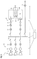
- FIG. 1 shows an integrated solution for a gas liquefaction plant 1 with an island power plant 23 as a power generation part 2, a transmission part 3 for the distribution of energy and a refrigerant compressor part 4.
- a control device 5 is connected to the power generation part 2, the transmission part 3 and the refrigerant compressor part 4.
- the power generation part 2 comprises three turbo sets 6, each having a turbine 10 and a generator 12, which are connected via a shaft 11. However, the power generation part 2 may also comprise less than three or more than three turbo sets 6.
- turbo sets 6 are connected in each case via an electrical transformer 13 to the power station busbar 15 of the transmission part 3, which provides the electrical energy to the motors in the refrigerant compressor part 4 and / or other consumers 26.
- variable-speed electric motors 8 of the refrigerant compressor 7 are driven via converter transformers 14 and converters 16.
- Drive motors 8 and refrigerant compressor 7 are connected via shafts 17 and form engine compressor trains 9, which ultimately cause the refrigerant circulation and cooling of the natural gas 21 in the refrigerant circuit 18.
- FIG. 1 shows a schematic representation of the closed refrigerant circuit 18.
- Compressed refrigerant is transported from the refrigerant compressor 7 via lines 19 to the liquefaction unit 25. Used gaseous refrigerant is returned via lines 20 to the refrigerant compressors 7.
- FIG. 1 shows FIG. 1 at the liquefaction unit 25 an inlet for light, gaseous hydrocarbons, such as natural gas 21.
- gaseous hydrocarbons such as natural gas 21.
- the natural gas 21 goes from the gaseous to the liquid phase (LNG) 22 by cooling in heat exchangers above.
- FIG. 2 shows the algorithm of a load computer of the control device 5 for controlling the uninterrupted operation of a gas liquefaction plant 1.
- the information includes the currently delivered power of each gas turbine, the currently possible maximum power of each gas or steam turbine set and the currently possible minimum load of each gas or steam turbine, expressed in each case in electrical generator power. Based on the power delivered and the currently possible maximum power or on the basis of the output power and the currently possible minimum load, the positive or negative load reserve can be determined.
- the dynamic load calculator computes the total currently available positive load reserve, taking into account various parameters, e.g. the current ambient temperature, the humidity and the calorific value of the fuel gas, which are already taken into account in the values 101 from the power plant control technology.
- the dynamic load calculator compares the positive load reserve with the power of the largest turbo set 6. If the total positive load reserve is sufficient to maintain the operation of the eLNG system even if a turbo set 6 is switched off, the dynamic load calculator reports to the wait staff 104. When the power plant and the eLNG system actually have a power cut-out in the power plant, the dynamic load calculator remains passive and the power plant control system balances the remaining available generators 12 with the balance between available and requested load come back.
- the dynamic load calculator determines that the currently available positive power reserve is not sufficient to compensate for the possible failure of a turbo set 6, it proactively notifies the alarm status "n + 1 not available" 105 to the waiting.
- the dynamic load calculator can intervene by temporarily reducing the speed of all operational compressor drives to a value that still ensures the stability of the compressor and thus ensures the freedom of production interruption.
- the information 106 obtained from the compressor control technology is processed continuously by reducing the compressor speed without jeopardizing the stability of the compressor operation, and adds the sum of the possible load reduction of the individual compressor units to the positive load reserve 107. The total achieved thereby Power reserve then possibly covers the failure of a turbo set 6.
- the associated algorithm is in FIG. 3 shown.
- 107 denotes the sum of the positive load reserve of the turbo sets 6 and the possible load reduction due to a reduction in the speed of the compressor units.
- the positive load reserve and the possible load reduction are compared with the currently available power of the largest turbo set 6. Regardless of the result of the comparison, the failure 110 of a turbine 10, the conjunction 110 is true and the speed of the compressor units is reduced 111. If the sum of positive load reserve and possible load reduction is smaller than the performance of the largest or at least affected turbo set 6, additionally takes place a load shedding 112th
- an independent determination of the line frequency change rate (df / dt) can be used to detect a sudden change in the load conditions - regardless of their cause.
- the rate of change of frequency is proportional to the respective load step and can thus be used to determine the necessary protection shutdowns.
- the dynamic load computer initiates a chain of preprogrammed load drops when predefined underfrequency thresholds are reached, in order to prevent a further lowering of the network frequency and thus a protective shutdown of the entire power plant.
- the stored in the load computer consumers which may be temporarily shut down, without interrupting production, are as fast and to the extent necessary disconnected from the network, as required to maintain the grid frequency.
- the algorithm applied to the unplanned shutdown of turbo sets 6 is also applicable to the unplanned shutdown of large consumers, especially the large compressor drives.
- the power plant and machine control technology is designed so that it can compensate for load shedding of this magnitude without the involvement of the dynamic load calculator.
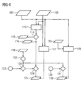
- FIG. 4 shows the principle.
- the dynamic load calculator does not intervene. Otherwise, a preselected turbo set 6 is turned off and the resulting positive load reserve offsets the remaining gap.
- step 113 designates the calculation of the negative load reserve and the determination of the compressor units with the largest load. In step 114, these two values are compared. If the negative load reserve is greater than the larger load of the compressor units, the calculator reports "n + 1 available” 115. Otherwise, it reports "n + 1 not available” 116.
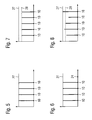
- FIG. 5 schematically shows the turbine load in a conventional power generation part of a gas liquefaction plant 1 in nominal operation. All turbines 10 of the power generation part run under nominal full load 27. The so operated power generation part has no positive load reserve to ensure the failure of a turbo set 6 the uninterrupted operation of the entire gas liquefaction plant.
- FIG. 6 schematically shows the turbine utilization, im in the US Pat. No. 7,114,351 B2 described power generation part of a gas liquefaction plant in nominal operation.
- the additional turbine 24, which is kept ready in standby mode, is started in the event of the failure of another turbine 10 operating under full load during nominal operation of the gas liquefaction plant.
- Interruptions and downtimes in the LNG production process can be the result of a failure of a turbine 10 and it may take several hours until the affected refrigerant compressor 7 is restarted and the liquefaction process is thermally stabilized.
- FIG. 7 shows schematically and by way of example the turbine utilization in the power generation part 2 of a gas liquefaction plant 1 according to the invention in nominal operation for the refrigerant compressor part 4. All turbines 10 run under partial load 28. There is no standby turbine 24. The positive load reserve is sufficient in case of failure of a turbine 10 by increasing the Load of the remaining turbines 10 to ensure the uninterrupted operation of the gas liquefaction plant 1.
- FIG. 8 shows schematically and by way of example an alternative turbine utilization in the power generation part 2 of a gas liquefaction plant 1 according to the invention in nominal operation for the refrigerant compressor part 4. All turbines 10 run under partial or full load 28,27. Again, there is no standby turbine 24. However, the utilization of the turbines 10 is not necessarily the same. For example, among other parameters, the engine life of the turbines 10 in the Determining the utilization machine-specific consideration.
Abstract
Description
Die Erfindung betrifft eine Gasverflüssigungsanlage, insbesondere eine Erdgasverflüssigungsanlage, und bezieht sich auf die Bereitstellung elektrischer Energie für den unterbrechungsfreien Betrieb einer solchen Gasverflüssigungsanlage. Die Erfindung betrifft ferner ein Verfahren zum unterbrechungsfreien Betrieb einer Gasverflüssigungsanlage.The invention relates to a gas liquefaction plant, in particular a natural gas liquefaction plant, and relates to the provision of electrical energy for the uninterrupted operation of such a gas liquefaction plant. The invention further relates to a method for uninterrupted operation of a gas liquefaction plant.
Als verflüssigtes Erdgas (Abkürzung LNG für engl. liquefied natural gas) bezeichnet man durch Abkühlung verflüssigtes Erdgas. LNG hat weniger als 1/600stel des Volumens von Erdgas bei atmosphärischem Druck und eignet sich daher besonders zu Transport- und Lagerungszwecken; als Brennstoff kann es in diesem Aggregatzustand nicht verwendet werden.As liquefied natural gas (abbreviation LNG for English liquefied natural gas) is called by liquefaction liquefied natural gas. LNG has less than 1 / 600th of the volume of natural gas at atmospheric pressure and is therefore particularly suitable for transport and storage purposes; as fuel, it can not be used in this state of aggregation.
In Kraftwerken, die einer Anlage zur Verflüssigung leichter Kohlenwasserstoffe, wie z.B. Erdgas, vorgeschaltet sind, kommen üblicherweise mit Erdgas befeuerte Gasturbinen sowie gegebenenfalls Dampfturbinen zum Einsatz, um über die angekuppelten Generatoren die elektrische Energie bereitzustellen, die motorgetrieben benötigt wird.In power plants operating a liquefaction plant for light hydrocarbons, e.g. Natural gas, upstream, usually come with natural gas-fired gas turbines and optionally steam turbines used to provide the coupled generators, the electrical energy that is needed motor-driven.
In konventionellen Erdgasverflüssigungsanlagen werden die Turboverdichter für den Kältemittelkreislauf durch direkt gekuppelte Gasturbinen angetrieben.In conventional natural gas liquefaction plants, the turbo compressors for the refrigerant circuit are driven by directly coupled gas turbines.
Gattungsmäßige Nachteile dieser Anlagen sind Produktionsausfall bei den erforderlichen regelmäßigen Wartungsarbeiten an den Gasturbinen, schwieriges An- oder Wiederanfahren der Verdichter mit Einwellengasturbinen, sowie die direkte Abhängigkeit der Größe und der Leistungsabgabe der Kältemittelverdichter von den typgeprüften Gasturbinen selbst, deren Wellenleistung wiederum von täglich schwankenden oder saisonal sich ändernden Umgebungsbedingungen abhängt.Generic disadvantages of these systems are production loss during the required regular maintenance of the gas turbines, difficult starting or restarting the compressors with single-shaft gas turbines, as well as the direct dependence of the size and the output of the refrigerant compressor of the type-tested gas turbine itself, whose shaft performance in turn fluctuates from daily to seasonal depending on changing environmental conditions.
Zur Vermeidung dieser Nachteile werden in neueren Anlagen die Kältemittelverdichter durch wartungsfreie drehzahlgeregelte Elektromotoren angetrieben. Ein von einer Gas- oder Dampfturbine angetriebener elektrischer Generator liefert die elektrische Leistung für diese Motoren; vorgeschaltete statische Frequenzumrichter erlauben einen sanften Anlauf und drehzahlgeregelten Betrieb. Man spricht dann auch von einer eLNG-Anlage (e für electric).To avoid these disadvantages, the refrigerant compressors are driven by maintenance-free speed-controlled electric motors in newer systems. An electric generator driven by a gas or steam turbine supplies the electric power for these motors; upstream static frequency inverters allow smooth start-up and speed-controlled operation. This is also referred to as an eLNG system (e for electric ).
Die
Elektromotoren liefern ihre Nennleistung unter verschiedenen Betriebsbedingungen, was einen Dauerbetrieb der Kältemittelverdichter ermöglicht, selbst bei wechselnden Umgebungsbedingungen, unterschiedlichem Gas, oder unterschiedlichen Lufteingangstemperaturen an den Gasturbinen. Die
Aufgabe der Erfindung ist daher die Angabe einer hochverfügbaren Gasverflüssigungsanlage sowie ein Verfahren für den unterbrechungsfreien Betrieb einer Gasverflüssigungsanlage.The object of the invention is therefore to specify a highly available gas liquefaction plant and a process for the uninterrupted operation of a gas liquefaction plant.
Erfindungsgemäß wird die auf den unterbrechungsfreien Betrieb einer Gasverflüssigungsanlage gerichtete Aufgabe gelöst durch eine Gasverflüssigungsanlage, umfassend einen Energieerzeugungsteil, einen Übertragungsteil, einen Kältemittelverdichterteil und eine Regeleinrichtung, wobei der Energieerzeugungsteil eine Anzahl von Turbosätzen und der Kältemittelverdichterteil mindestens einen Kältemittelverdichter und einen an den Kältemittelverdichter angekoppelten Antriebsmotor zum elektrischen Antrieb des Kältemittelverdichters aufweisen, der Übertragungsteil die im Energieerzeugungsteil erzeugte Leistung dem Kältemittelverdichterteil zur Verfügung stellt und die Regeleinrichtung mit dem Energieerzeugungsteil und dem Kältemittelverdichterteil verbunden ist, wobei über die Regeleinrichtung im Normalbetrieb die für den Nennbedarf erforderliche Leistung durch den Teil- oder Volllastbetrieb aller Turbosätze bereitstellbar ist, und die Anzahl der Turbosätze die Mindestanzahl übersteigt, die notwendig ist, die Kontinuität des Betriebs des Kältemittelverdichterteils sicherzustellen.According to the invention, the object directed to the uninterrupted operation of a gas liquefaction plant is achieved by a gas liquefaction plant comprising a power generation part, a transmission part, a refrigerant compressor part and a control device, wherein the power generation part comprises a number of turbo sets and the refrigerant compressor part at least one refrigerant compressor and a drive motor coupled to the refrigerant compressor having electrical drive of the refrigerant compressor, the transmission part provides the power generated in the power generation part of the refrigerant compressor part and the control device is connected to the power generation part and the refrigerant compressor part, wherein the control device in normal operation required for the nominal power required by the partial or full load operation of all turbo sets is available, and the number of turbo sets the minimum number exceeds that is necessary to ensure the continuity of the operation of the refrigerant compressor unit.
Die Erfindung beruht demnach auf dem Gedanken, einen zusätzlichen Turbosatz, gemessen am Gesamt-Leistungsbedarf der eLNG-Anlage, dem n+1 Prinzip folgend, zu installieren. Dieser Turbosatz ist kein Standby-Turbosatz. Alle zum Betrieb der eLNG-Anlage notwendigen Turbosätze, einschließlich dem n+1ten Turbosatz, arbeiten im ungestörten bzw. Normalzustand der Anlage im Teillastbetrieb, d.h. es wird jeweils so viel rotierende Reserve vorgehalten, dass der Ausfall eines Turbosatzes regelungstechnisch ausgeglichen werden kann. Dabei können einer oder mehrere designierte Turbosätze die Frequenzregelung übernehmen und alle operativen Turbosätze werden im Normalfall gleichmäßig belastet. Bei Schutzabschaltungen (trip) einer Turbine oder eines Generators entscheidet eine Regeleinrichtung (dynamischer Lastrechner), ob Maßnahmen zur Stabilisierung des Inselnetzes eingeleitet werden müssen oder nicht.The invention is therefore based on the idea to install an additional turbo set, based on the total power requirement of the eLNG system, following the n + 1 principle. This turbo set is not a standby turbo set. All turbo sets necessary for the operation of the eLNG system, including the n + 1th turbo set, operate in the undisturbed or normal state of the system in part-load operation, ie in each case so much rotating reserve is provided that the failure of a turbo set can be compensated by control technology. One or more designated turbo sets can take over the frequency control and all operational turbo sets are normally loaded evenly. In protective shutdowns (trip) of a turbine or a generator decides a control device (dynamic load computer), whether measures to stabilize the island grid must be initiated or not.
Der für den Betrieb der eLNG-Anlage schwerwiegendste zu erwartende Fehler ist der ungeplante Ausfall eines Turbosatzes im Energieerzeugungsteil, also im Inselkraftwerk - Schutzabschaltungen von Verdichterantrieben sind in ihren Auswirkungen untergeordnet und bei Notabschaltungen in der Prozessanlage kann der Betrieb unter Umständen nicht aufrechterhalten werden. Prinzipiell kann aber auch eine partielle Notabschaltung (ESD, emergency shut down) in der Prozessanlage in den Algorithmus des dynamischen Lastrechners mit einbezogen werden.The most serious fault expected for the operation of the eLNG system is the unplanned failure of a turbo set in the power generation part, ie in the island power plant - protection shutdowns of compressor drives are subordinate in their effects and in emergency shutdowns in the process plant, the operation may not be maintained. In principle, however, a partial emergency shutdown (ESD, emergency shutdown) in the process plant can also be included in the algorithm of the dynamic load calculator.
Die damit prinzipiell mögliche unterbrechungsfreie Betriebsdauer der Gasverflüssigungsanlage wird durch Wegfall notwendiger Wartungsarbeiten an den Gasturbinen im Energieerzeugungsteil von bisher ein bis zwei auf mehr als fünf Jahre erhöht. Einer Erhöhung der voraussehbaren produktiven Tage von circa 340 (bisheriger Erfahrungswert mit direkt getriebenen Gasverflüssigungsanlagen) auf 365 pro Jahr stehen dann nur noch ungeplante (Stör-)Abschaltungen entgegen.The thus possible in principle uninterrupted operating life of the gas liquefaction plant is increased by eliminating the need for maintenance work on the gas turbines in the power generation part of previously one to two to more than five years. An increase in foreseeable productive days of around 340 (previous experience with directly driven gas liquefaction plants) to 365 per year is then only precluded by unplanned (disruptive) shutdowns.
Bei Einsatz von drehzahlgeregelten (stromrichtergespeisten) Elektromotoren und Speisung derselben aus einem modernen GuD-Kraftwerk erhöht sich der thermische Wirkungsgrad der Anlage und der Ausstoß von Treibhausgasen wird reduziert.The use of variable-speed (converter-fed) electric motors and feeding them from a modern combined cycle power plant increases the thermal efficiency of the plant and greenhouse gas emissions are reduced.
Durch geeignete Auslegung der Antriebsanlagen können die Kältemittelverdichter nach einer prozessbedingten Abschaltung innerhalb von 10 bis 30 Minuten anstatt in 8 bis 12 Stunden im Fall von Standby-Turbinen oder Festdrehzahl-Elektromotoren mit Anfahrumrichtern wieder angefahren werden, ohne die Verdichter zu entlasten und ohne Kältemittel abzufackeln.By suitable design of the drive systems, the refrigerant compressor can be restarted after a process-related shutdown within 10 to 30 minutes instead of 8 to 12 hours in the case of standby turbines or fixed-speed electric motors with Anfahrumrichtern without relieving the compressors and flare without refrigerant.
Bei entsprechender Auslegung des speisenden Inselkraftwerks und Integration der beteiligten Automatisierungssysteme (z. B. Kraftwerk, Stromrichterantriebe, Verdichter) kann die Produktion der eLNG-Anlage auch während der Störabschaltung eines Generators im Kraftwerk unterbrechungsfrei aufrechterhalten werden.With an appropriate design of the feeding island power plant and integration of the participating automation systems (eg power plant, converter drives, compressors), the production of the eLNG system can be maintained without interruption during the lockout of a generator in the power plant.
Das Personengefährdungspotenzial wird durch Verlagerung von Wartungsarbeiten aus dem explosionsgefährdeten Prozessbereich in den Kraftwerksbereich reduziert.The risk to persons is reduced by shifting maintenance work from the potentially explosive process area to the power plant area.
Die Einengung der Verdichterauswahlkriterien auf die Drehzahl und Leistung der Gasturbinen weicht bei Einsatz von anwendungsspezifisch ausgelegten drehzahlgeregelten Elektromotoren einer Optimierung nach Prozessgegebenheiten.The narrowing of the compressor selection criteria to the speed and power of the gas turbine differs when using application-specific designed variable speed electric motors of an optimization according to process conditions.
Im erfinderischen Verfahren zum unterbrechungsfreien Betrieb einer Gasverflüssigungsanlage, umfassend einen Energieerzeugungsteil, einen Übertragungsteil, einen Kältemittelverdichterteil und eine Regeleinrichtung, wobei der Energieerzeugungsteil eine Anzahl von Turbosätzen und der Kältemittelverdichterteil mindestens einen Kältemittelverdichter und einen an den Kältemittelverdichter angekoppelten Antriebsmotor zum elektrischen Antrieb des Kältemittelverdichters mit einem elektrischen Nennbedarf aufweisen, der Übertragungsteil die im Energieerzeugungsteil erzeugte Leistung dem Kältemittelverdichterteil zur Verfügung stellt, und die Regeleinrichtung mit dem Energieerzeugungsteil und dem Kältemittelverdichterteil verbunden ist, wird im Normalbetrieb die für den Nennbedarf erforderliche Leistung durch den Teil- oder Volllastbetrieb aller Turbosätze bereitgestellt, wobei die Anzahl der Turbosätze die Mindestanzahl übersteigt, die notwendig ist, die Stabilität des Betriebs des Kältemittelverdichterteils sicherzustellen.In the inventive method for uninterrupted operation of a gas liquefaction plant, comprising a power generation part, a transmission part, a refrigerant compressor part and a control device, wherein the power generation part includes a number of turbo sets and the refrigerant compressor part at least one refrigerant compressor and a coupled to the refrigerant compressor drive motor for electrically driving the refrigerant compressor with an electric Have nominal requirements, the transmission part provides the power generated in the power generation part of the refrigerant compressor part, and the control device is connected to the power generation part and the refrigerant compressor part, the power required for the nominal demand is provided by the partial or full load operation of all turbo sets in normal operation, the number turbo sets exceeds the minimum number necessary to ensure the stability of operation d to ensure the refrigerant compressor part.
Vorteilhafterweise werden alle zum Betrieb der Gasverflüssigungsanlage notwendigen Turbosätze im Normalbetrieb der Verflüssigungsanlage und der Turbosätze bei Teillast betrieben.Advantageously, all necessary to operate the gas liquefaction turbine sets are operated in normal operation of the liquefaction plant and the turbo sets at part load.
Vorzugsweise werden alle operativen Generatoren im Normalfall gleichmäßig belastet werden.Preferably, all operational generators will normally be charged evenly.
Damit die Regeleinrichtung schnell und exakt arbeitet, ist es zweckmäßig, dass die Regeleinrichtung kontinuierlich Informationen aus der Kraftwerksleittechnik und aus der Verdichterleittechnik erhält.In order for the control device to work quickly and accurately, it is expedient for the control device to continuously receive information from the power plant control technology and from the compressor control technology.
Ein unterbrechungsfreier Betrieb der Gasverflüssigungsanlage lässt sich am ehesten dadurch erreichen, dass die Turbosätze so betrieben werden, dass eine vorgehaltene positive oder negative Leistungsreserve den Ausfall der größten Turbomaschine deckt, wobei die positive Leistungsreserve den Ausfall eines Generators deckt und die negative Leistungsreserve den Ausfall eines Motor-Verdichterstrangs des Kältemittelverdichterteils.Uninterrupted operation of the gas liquefaction plant can best be achieved by operating the turbo sets so that a positive or negative power reserve covers the failure of the largest turbomachine, with the positive power reserve covering one generator failure and the negative power reserve covering the failure of one engine Compressor line of the refrigerant compressor part.
Bei Ausfall eines Turbosatzes wird vorzugsweise die Verdichterantriebsdrehzahl abgesenkt, wenn eine zuvor bestimmte gesamte positive Lastreserve kleiner ist, als die erbrachte Leistung des Turbosatzes vor dem Ausfall. (Der quadratischen Lastkennlinie der Turboverdichter folgend, reduziert sich die von den Elektromotoren aufgenommene Leistung mit der dritten Potenz der Drehzahl).In case of failure of a turbo set, the compressor drive speed is preferably lowered when a previously determined total positive load reserve is smaller than the yielded power of the turbo set before failure. (Following the quadratic load curve of the turbocompressors, the power consumed by the electric motors decreases with the cube of the speed).
Wird auch durch die Reduzierung der Verdichterantriebsdrehzahl der aktuelle Energiebedarf des Kältemittelverdichterteils nicht gedeckt, ist es zweckmäßig, vorbestimmte elektrische Verbraucher der Gasverflüssigungsanlage abzuschalten (englisch load shedding).If the current energy requirement of the refrigerant compressor part is not covered by the reduction of the compressor drive speed, it is expedient to switch off predetermined electrical consumers of the gas liquefaction system (English load shedding).
Der weitestgehend unterbrechungsfreie Betrieb der Gasverflüssigungsanlage bei ungewollter Abschaltung von Teilanlagen im Verflüssigungsprozess oder beim Überschreiten der vorgegebenen Grenzwerte für die Netzfrequenz und deren zeitlicher Änderung, Spannung und Phasenwinkel im Energieversorgungsnetz der Gasverflüssigungsanlage kann dadurch sichergestellt werden, dass vorbestimmte Turbinen abgeschaltet werden.The largely uninterrupted operation of the gas liquefaction plant in case of accidental shutdown of subsystems in the liquefaction process or exceeding the preset limits for the grid frequency and its temporal change, voltage and phase angle in the energy supply network of the gas liquefaction plant can be ensured that predetermined turbines are turned off.
Ist die negative Lastreserve kleiner als der Energiebedarf des größten Kältemittelverdichters und fällt entweder ein Kältemittelverdichter aus oder überschreiten die vorgegebenen Grenzwerte für die Netzfrequenz und deren zeitlicher Änderung, Spannung und Phasenwinkel im Energieversorgungsnetz der Gasverflüssigungsanlage eine vorgegebene Grenze, ist es zweckmäßig, vorbestimmte Turbinen abzuschalten.If the negative load reserve is smaller than the energy requirement of the largest refrigerant compressor and either a refrigerant compressor fails or exceeds the specified limits for the mains frequency and its time change, Voltage and phase angle in the energy supply network of the gas liquefaction plant a predetermined limit, it is expedient to turn off predetermined turbines.
Die Erfindung wird beispielhaft anhand der Zeichnungen näher erläutert. Es zeigen schematisch und nicht maßstäblich:
- Figur 1
- eLNG-Anlagenkonzept
Figur 2- Lastrechner-Algorithmus der Regeleinrichtung für die positive Lastreserve
Figur 3- Lastrechner-Algorithmus der Regeleinrechnung für die Reduzierung der Drehzahl der Verdichtereinheiten
Figur 4- Lastrechner-Algorithmus der Regeleinrichtung für die Abschaltung vorgewählter Turbinen
Figur 5- Turbinenauslastung in konventionellem Energieerzeugungsteil einer Gasverflüssigungsanlage
Figur 6- Turbinenauslastung im Energieerzeugungsteil einer Gasverflüssigungsanlage mit Standby-Turbine
Figur 7- Turbinenauslastung im Energieerzeugungsteil einer Gasverflüssigungsanlage mit n+1 Turbinen im Teillastbetrieb
Figur 8- alternative Turbinenauslastung im Energieerzeugungsteil einer Gasverflüssigungsanlage mit n+1 Turbinen
- FIG. 1
- eLNG investment concept
- FIG. 2
- Load calculator algorithm of the control device for the positive load reserve
- FIG. 3
- Load calculator algorithm of the control calculation for the reduction of the speed of the compressor units
- FIG. 4
- Load calculator algorithm of the control device for switching off selected turbines
- FIG. 5
- Turbine utilization in conventional power generation part of a gas liquefaction plant
- FIG. 6
- Turbine utilization in the power generation part of a gas liquefaction plant with standby turbine
- FIG. 7
- Turbine utilization in the power generation part of a gas liquefaction plant with n + 1 turbines in partial load operation
- FIG. 8
- alternative turbine utilization in the power generation section of a gas liquefaction plant with n + 1 turbines
Die
Der Energieerzeugungsteil 2 umfasst drei Turbosätze 6, mit jeweils einer Turbine 10 und einem Generator 12, die über eine Welle 11 verbunden sind. Der Energieerzeugungsteil 2 kann aber auch weniger als drei oder mehr als drei Turbosätze 6 umfassen.The
Die Turbosätze 6 sind über jeweils einen elektrischen Transformator 13 mit der Kraftwerksstromschiene 15 des Übertragungsteils 3 verbunden, welcher die elektrische Energie den Motoren im Kältemittelverdichterteil 4 und/oder anderen Verbrauchern 26 zur Verfügung stellt.The turbo sets 6 are connected in each case via an
Im Kältemittelverdichterteil 4 werden über Stromrichtertransformatoren 14 und Stromrichter 16 die drehzahlveränderbaren Elektromotoren 8 der Kältemittelverdichter 7 angetrieben. Antriebsmotoren 8 und Kältemittelverdichter 7 sind über Wellen 17 verbunden und bilden Motor-Verdichterstränge 9, die letztlich die Kältemittelzirkulation und Kühlung des Erdgases 21 im Kältemittelkreislauf 18 bewirken.In the
Die
Weiterhin zeigt die
In einem ersten Schritt 102 berechnet der dynamische Lastrechner die insgesamt momentan verfügbare positive Lastreserve unter Einbeziehung verschiedener Parameter, wie z.B. der momentanen Umgebungstemperatur, der Luftfeuchte und des Brennwertes des Brenngases, die bereits in den Werten 101 aus der Kraftwerksleittechnik berücksichtigt sind.In a
In einem zweiten Schritt 103 vergleicht der dynamische Lastrechner die positive Lastreserve mit der Leistung des größten Turbosatzes 6. Reicht die gesamte positive Lastreserve auch bei Abschaltung eines Turbosatzes 6 aus, den Betrieb der eLNG-Anlage aufrecht zu erhalten, meldet der dynamische Lastrechner an die Warten des Kraftwerks und der eLNG-Anlage den Zustand "n+1 verfügbar" 104. Erfolgt in diesem Zustand wirklich eine Schutzabschaltung im Kraftwerk, bleibt der dynamische Lastrechner passiv, und die Kraftwerksleittechnik stellt durch Umlastung der verbliebenen Generatoren 12 das Gleichgewicht zwischen verfügbarer und angeforderter Last wieder her.In a
Stellt der dynamische Lastrechner fest, dass die momentan verfügbare positive Leistungsreserve nicht ausreicht, um den möglichen Ausfall eines Turbosatzes 6 zu kompensieren, meldet er den Alarmzustand "n+1 nicht verfügbar" 105 prophylaktisch an die Warten.If the dynamic load calculator determines that the currently available positive power reserve is not sufficient to compensate for the possible failure of a turbo set 6, it proactively notifies the alarm status "n + 1 not available" 105 to the waiting.
Dies ermöglicht es dem Bedienpersonal eventuell stillgesetzte Leistungsreserven (z.B. durch Wartungsarbeiten) zu mobilisieren, oder die Belastung des Netzes zu reduzieren, z.B. durch Abschaltung anderer Verbraucher 26, und damit ggf. einer Produktionsunterbrechung bei Ausfall eines Turbosatzes 6 vorzubeugen. Auch manuelle Umlastungen zwischen den operativen Turbosätzen 6 und Änderungen im Prozessdampfverbrauch sind dazu geeignet.This allows the operator possibly immobilized power reserves (eg by maintenance) to mobilize or reduce the load on the network, eg by switching off
Wird die prophylaktische Lastreduzierung nicht vom Bedienpersonal der eLNG-Anlage initiiert, z.B. durch Abschaltung unwichtiger Verbraucher 26 oder temporärer Reduktion der Produktion, kann der dynamische Lastrechner eingreifen, indem er die Drehzahl aller operativen Verdichterantriebe temporär auf einen Wert absenkt, der die Stabilität des Verdichters noch sicherstellt und damit die Unterbrechungsfreiheit der Produktion gewährleistet. Hierzu wird die aus der Verdichterleittechnik erhaltene Information 106 zu den momentan möglichen Lastreduzierungen durch Senkung der Verdichter-Drehzahl, ohne die Stabilität des Verdichterbetriebs zu gefährden, kontinuierlich verarbeitet und die Summe der möglichen Lastreduzierung der einzelnen Verdichtereinheiten zur positiven Lastreserve addiert 107. Die dadurch erzielte gesamte Leistungsreserve deckt dann möglicherweise den Ausfall eines Turbosatzes 6.If the prophylactic load reduction is not initiated by the operator of the eLNG system, e.g. By shutting down
Im Alarmzustand "n+1 nicht verfügbar" kann also das Gleichgewicht zwischen positiver und negativer Lastreserve durch eine Absenkung der Verdichterantriebsdrehzahl wieder hergestellt werden. Da dieser Vorgang sehr schnell erfolgen kann, wird er vom dynamischen Lastrechner nur ausgelöst, wenn im Alarmzustand wirklich eine Schutzabschaltung im Kraftwerk erfolgt.In the alarm state "n + 1 not available" so the balance between positive and negative load reserve can be restored by lowering the compressor drive speed. Since this process can be carried out very quickly, it is only triggered by the dynamic load computer if, in the alarm state, a protective shutdown is actually performed in the power plant.
Der zugehörige Algorithmus ist in
Neben der rechnerischen Ermittlung der Differenz zwischen positiver und negativer Lastreserve kann eine unabhängige Bestimmung der Netzfrequenz-Änderungsgeschwindigkeit (df/dt) dazu benutzt werden, eine plötzliche Veränderung der Lastverhältnisse zu erkennen - ohne Rücksicht auf deren Ursache. Die Frequenz-Änderungsgeschwindigkeit ist proportional zum jeweiligen Lastsprung und kann somit zur Bestimmung der notwendigen Schutzabschaltungen verwendet werden.In addition to the mathematical determination of the difference between positive and negative load reserve, an independent determination of the line frequency change rate (df / dt) can be used to detect a sudden change in the load conditions - regardless of their cause. The rate of change of frequency is proportional to the respective load step and can thus be used to determine the necessary protection shutdowns.
Da eine Frequenzänderung eine direkte Konsequenz des auslösenden Ereignisses ist, und die Bestimmung der Änderungsgeschwindigkeit mehr Zeit benötigt als eine Schutzauslösung über die direkten Abschaltsignale, würde eine Aktion aus der errechneten Frequenzänderung ggf. zu spät kommen. Deshalb kann diese Funktion als Backup zur beschriebenen direkten Abschaltung angesehen werden. Außerdem muss sichergestellt sein, dass Aktionen, die aus der rechnerischen Ermittlung der Unterfrequenz resultieren, keine Fehlauslösungen verursachen.Since a frequency change is a direct consequence of the triggering event, and the determination of the rate of change requires more time than a protection trip via the direct shutdown signals, an action from the calculated frequency change might be too late. Therefore, this function can be considered a backup to the described direct shutdown. It must also be ensured that actions resulting from the calculation of the underfrequency do not cause false tripping.
Reichen die beschriebenen Maßnahmen zum Ausgleich des Unterschieds zwischen positiver und negativer Lastreserve nicht aus, initiiert der dynamische Lastrechner eine Kette von vorprogrammierten Lastabwürfen bei Erreichen von vordefinierten Unterfrequenzschwellen, um ein weiteres Absenken der Netzfrequenz - und damit einer Schutzabschaltung des gesamten Kraftwerks - vorzubeugen. Die im Lastrechner hinterlegten Verbraucher, die ggf. zeitweise abgeschaltet werden können, ohne die Produktion zu unterbrechen, werden so schnell und im notwendigen Umfang vom Netz getrennt, wie es die Aufrechterhaltung der Netzfrequenz erfordert.If the described measures for compensating the difference between positive and negative load reserve are insufficient, the dynamic load computer initiates a chain of preprogrammed load drops when predefined underfrequency thresholds are reached, in order to prevent a further lowering of the network frequency and thus a protective shutdown of the entire power plant. The stored in the load computer consumers, which may be temporarily shut down, without interrupting production, are as fast and to the extent necessary disconnected from the network, as required to maintain the grid frequency.
Prinzipiell ist der auf die ungeplante Abschaltung von Turbosätzen 6 angewandete Algorithmus auch anwendbar auf die ungeplante Abschaltung großer Verbraucher, vor allem der großen Verdichterantriebe. Die Kraftwerks- und Maschinenleittechnik ist so ausgelegt, dass sie Lastabwürfe dieser Größenordnung ohne Mitwirkung des dynamischen Lastrechners ausregeln kann.
Ist die Summe der durch Frequenzregelung erreichbaren negativen Lastreserve größer als der größte anzunehmende Lastabwurf durch Abschaltung von Verdichterantrieben, greift der dynamische Lastrechner nicht ein. Andernfalls wird ein vorgewählter Turbosatz 6 abgeschaltet und die resultierende positive Lastreserve gleicht die verbleibende Lücke aus.If the sum of the negative load reserve achievable by frequency control is greater than the largest load shedding to be assumed by shutting down compressor drives, the dynamic load calculator does not intervene. Otherwise, a preselected turbo set 6 is turned off and the resulting positive load reserve offsets the remaining gap.
113 bezeichnet hierbei die Berechnung der negativen Lastreserve und die Bestimmung der Verdichtereinheiten mit der größten Last. Im Schritt 114 werden diese beiden Werte verglichen. Ist die negative Lastreserve größer als die größere Last der Verdichtereinheiten, meldet der Rechner "n+1 verfügbar" 115. Im anderen Fall meldet er "n+1 nicht verfügbar" 116.113 designates the calculation of the negative load reserve and the determination of the compressor units with the largest load. In
Anhand der Daten aus der Kraftwerksleittechnik 101 sowie der Verdichterleittechnik 106 erfolgt eine Zuordnung 117 von Turbosätzen 6 und Verdichtereinheiten. Mithilfe dieser Zuordnung werden vorgewählte Turbinen 10 abgeschaltet, wenn die negative Lastreserve kleiner ist 116 als der Energiebedarf der größten Verdichtereinheiten und 124 entweder eine Verdichtereinheit ausfällt 122 oder 123 die Frequenzänderungsgeschwindigkeit 120 im Energieversorgungsnetz der Gasverflüssigungsanlage 1 eine vorgegebene Grenze überschreitet 121.Based on the data from the power
Bei noch größeren Lastabwürfen 126, z.B. im Falle von partiellen Notabschaltungen aus dem Prozess, müssen ggf. mehrere Turbosätze 6 vom Netz genommen werden 128. Sind der Ablauf und die Größe 118 einer solchen Notabschaltung bekannt, kann auch ein solcher Vorgang vom Lastrechner prinzipiell gesteuert werden, z.B. indem eine Vorauswahl 119 abzuschaltender Turbinen 10 getroffen wird, um ggf. einen Teilprozess weiter betreiben zu können. Große Lastabwürfe 126 und das Überschreiten 121 einer Grenze der Frequenzänderungsgeschwindigkeit 120 sind im Sinne einer nicht-ausschließenden Disjunktion 127 miteinander verknüpft.For even larger load drops 126, eg in the case of partial emergency shutdowns from the process, several turbo sets 6 may have to be disconnected from the
Claims (19)
Priority Applications (7)
| Application Number | Priority Date | Filing Date | Title |
|---|---|---|---|
| EP07013711A EP2015011A1 (en) | 2007-07-12 | 2007-07-12 | Gas liquefaction facility and method for continuous operation of a gas liquefaction facility |
| RU2010104871/06A RU2458295C2 (en) | 2007-07-12 | 2008-07-08 | Method applied for uninterrupted operation of gas liquefaction plant |
| CN2008801043793A CN101784857B (en) | 2007-07-12 | 2008-07-08 | Method for the uninterrupted operation of a gas liquefaction system |
| US12/668,503 US20100257895A1 (en) | 2007-07-12 | 2008-07-08 | Method for the uninterrupted operation of a gas liquefaction system |
| PCT/EP2008/058821 WO2009007359A2 (en) | 2007-07-12 | 2008-07-08 | Method for the uninterrupted operation of a gas liquefaction system |
| EP08774867A EP2165137A2 (en) | 2007-07-12 | 2008-07-08 | Method for the uninterrupted operation of a gas liquefaction system |
| AU2008274289A AU2008274289B2 (en) | 2007-07-12 | 2008-07-08 | Method for the uninterrupted operation of a gas liquefaction system |
Applications Claiming Priority (1)
| Application Number | Priority Date | Filing Date | Title |
|---|---|---|---|
| EP07013711A EP2015011A1 (en) | 2007-07-12 | 2007-07-12 | Gas liquefaction facility and method for continuous operation of a gas liquefaction facility |
Publications (1)
| Publication Number | Publication Date |
|---|---|
| EP2015011A1 true EP2015011A1 (en) | 2009-01-14 |
Family
ID=39104484
Family Applications (2)
| Application Number | Title | Priority Date | Filing Date |
|---|---|---|---|
| EP07013711A Withdrawn EP2015011A1 (en) | 2007-07-12 | 2007-07-12 | Gas liquefaction facility and method for continuous operation of a gas liquefaction facility |
| EP08774867A Withdrawn EP2165137A2 (en) | 2007-07-12 | 2008-07-08 | Method for the uninterrupted operation of a gas liquefaction system |
Family Applications After (1)
| Application Number | Title | Priority Date | Filing Date |
|---|---|---|---|
| EP08774867A Withdrawn EP2165137A2 (en) | 2007-07-12 | 2008-07-08 | Method for the uninterrupted operation of a gas liquefaction system |
Country Status (6)
| Country | Link |
|---|---|
| US (1) | US20100257895A1 (en) |
| EP (2) | EP2015011A1 (en) |
| CN (1) | CN101784857B (en) |
| AU (1) | AU2008274289B2 (en) |
| RU (1) | RU2458295C2 (en) |
| WO (1) | WO2009007359A2 (en) |
Cited By (2)
| Publication number | Priority date | Publication date | Assignee | Title |
|---|---|---|---|---|
| WO2010118976A1 (en) * | 2009-04-16 | 2010-10-21 | Siemens Aktiengesellschaft | Method for operating several machines |
| EP2660547A1 (en) | 2012-05-03 | 2013-11-06 | Siemens Aktiengesellschaft | Metallurgical assembly |
Families Citing this family (9)
| Publication number | Priority date | Publication date | Assignee | Title |
|---|---|---|---|---|
| US8108081B2 (en) * | 2009-08-12 | 2012-01-31 | Sunpower Corporation | System and method for associating a load demand with a variable power generation |
| FR2977015B1 (en) * | 2011-06-24 | 2015-07-03 | Saipem Sa | METHOD FOR LIQUEFACTING NATURAL GAS WITH TRIPLE FIRM CIRCUIT OF REFRIGERATING GAS |
| EP2604960A1 (en) | 2011-12-15 | 2013-06-19 | Shell Internationale Research Maatschappij B.V. | Method of operating a compressor and system and method for producing a liquefied hydrocarbon stream |
| US9939194B2 (en) * | 2014-10-21 | 2018-04-10 | Kellogg Brown & Root Llc | Isolated power networks within an all-electric LNG plant and methods for operating same |
| JP6415989B2 (en) * | 2015-01-05 | 2018-10-31 | 三菱重工サーマルシステムズ株式会社 | Cooling device for liquefied gas |
| EP3339653B1 (en) | 2016-12-21 | 2021-07-07 | ABB Schweiz AG | Compressor control during power supply system disturbances |
| WO2019110770A1 (en) * | 2017-12-07 | 2019-06-13 | Shell Internationale Research Maatschappij B.V. | Method of operating a liquefied natural gas production facility |
| JP6556891B2 (en) * | 2018-03-09 | 2019-08-07 | 三菱重工サーマルシステムズ株式会社 | Cooling device for liquefied gas and maintenance method thereof |
| CN108561194B (en) * | 2018-04-27 | 2020-07-14 | 中国神华能源股份有限公司 | Primary frequency modulation control device and method for generator set |
Family Cites Families (6)
| Publication number | Priority date | Publication date | Assignee | Title |
|---|---|---|---|---|
| SU1359603A1 (en) * | 1985-12-25 | 1987-12-15 | Всесоюзный научно-исследовательский институт гелиевой техники | Method of controlling cryogenic unit modes of operation |
| DE19537637A1 (en) * | 1995-10-10 | 1997-04-17 | Asea Brown Boveri | Process for operating a power plant |
| EG24658A (en) * | 2002-09-30 | 2010-04-07 | Bpcorporation North America In | All electric lng system and process |
| US7069733B2 (en) * | 2003-07-30 | 2006-07-04 | Air Products And Chemicals, Inc. | Utilization of bogdown of single-shaft gas turbines to minimize relief flows in baseload LNG plants |
| WO2005047789A2 (en) * | 2003-11-06 | 2005-05-26 | Exxonmobil Upstream Research Company | Method for efficient, nonsynchronous lng production |
| JP4564376B2 (en) * | 2005-02-23 | 2010-10-20 | 株式会社東芝 | LNG power generation plant and its operation method |
-
2007
- 2007-07-12 EP EP07013711A patent/EP2015011A1/en not_active Withdrawn
-
2008
- 2008-07-08 US US12/668,503 patent/US20100257895A1/en not_active Abandoned
- 2008-07-08 EP EP08774867A patent/EP2165137A2/en not_active Withdrawn
- 2008-07-08 RU RU2010104871/06A patent/RU2458295C2/en not_active IP Right Cessation
- 2008-07-08 AU AU2008274289A patent/AU2008274289B2/en not_active Expired - Fee Related
- 2008-07-08 WO PCT/EP2008/058821 patent/WO2009007359A2/en active Application Filing
- 2008-07-08 CN CN2008801043793A patent/CN101784857B/en not_active Expired - Fee Related
Non-Patent Citations (6)
| Title |
|---|
| "THE ALL ELECTRIC DRIVEN LNG PLANT", BP UPSTREAM ENERGY CONFERENCE, XX, XX, 9 May 2001 (2001-05-09), pages 3 - 38, XP001544024 * |
| CORCORAN J C W ET AL: "Studies of machine dynamic behaviour and system recovery in a natural gas liquefaction plant", ADVANCES IN POWER SYSTEM CONTROL, OPERATION AND MANAGEMENT, 1991. APSCOM-91., 1991 INTERNATIONAL CONFERENCE ON HONG KONG, HONG KONG,IEE, 1991, pages 921 - 926, XP006512444, ISBN: 0-86341-246-7 * |
| FALLAIZE R A ET AL: "NEXT GENERATION LNG - EDRIVE", AICHE NATIONAL MEETING, XX, XX, 12 March 2002 (2002-03-12), pages 203 - 223, XP009050746 * |
| KLEINER F ET AL: "ALL ELECTRIC DRIVEN REFRIGERATION COMPRESSORS IN LNG PLANTS OFFER ADVANTAGES", GASTECH, XX, XX, 14 March 2005 (2005-03-14), pages 1 - 8, XP001544023 * |
| SHU ET AL: "Analysis points to electric-motor drivers for Angola LNG", OIL & GAS JOURNAL, 7 October 2002 (2002-10-07), XP009096700 * |
| WILSON R C ET AL: "Electrical Network Design Studies for Natural Gas Liquefaction Plants", THE 2006 IEEE INDUSTRY APPLICATIONS CONFERENCE FORTY-FIRST IAS ANNUAL MEETING, CONFERENCE RECORD OF, IEEE, PI, October 2006 (2006-10-01), pages 287 - 292, XP031026048, ISBN: 1-4244-0364-2 * |
Cited By (3)
| Publication number | Priority date | Publication date | Assignee | Title |
|---|---|---|---|---|
| WO2010118976A1 (en) * | 2009-04-16 | 2010-10-21 | Siemens Aktiengesellschaft | Method for operating several machines |
| EP2660547A1 (en) | 2012-05-03 | 2013-11-06 | Siemens Aktiengesellschaft | Metallurgical assembly |
| WO2013164297A1 (en) | 2012-05-03 | 2013-11-07 | Siemens Aktiengesellschaft | Metallurgical plant |
Also Published As
| Publication number | Publication date |
|---|---|
| WO2009007359A3 (en) | 2009-10-22 |
| CN101784857A (en) | 2010-07-21 |
| RU2010104871A (en) | 2011-08-20 |
| US20100257895A1 (en) | 2010-10-14 |
| WO2009007359A2 (en) | 2009-01-15 |
| CN101784857B (en) | 2012-09-26 |
| AU2008274289B2 (en) | 2012-12-13 |
| AU2008274289A1 (en) | 2009-01-15 |
| EP2165137A2 (en) | 2010-03-24 |
| RU2458295C2 (en) | 2012-08-10 |
Similar Documents
| Publication | Publication Date | Title |
|---|---|---|
| EP2015011A1 (en) | Gas liquefaction facility and method for continuous operation of a gas liquefaction facility | |
| DE112009000663B4 (en) | PROCEDURE FOR OPERATING A POWER PLANT | |
| EP2118997B1 (en) | Method for operating a power plant | |
| EP2312741B1 (en) | Method for early detection and anticipatory control of consumer-end load shedding in an electrical grid, and apparatus for carrying out the method | |
| EP2122129B1 (en) | Power plant system and method for the operation thereof | |
| EP2115274B1 (en) | Method for operating a power plant | |
| EP2260193B1 (en) | Method for regulating a gas turbine in a power plant and power plant to carry out the method | |
| EP1433238B1 (en) | Method for operating a wind park | |
| EP1795725B1 (en) | Gas turbine with controlled air cooling | |
| DE102005038558A1 (en) | Method for operating a wind energy plant park and wind energy plant park | |
| DE102008037449A1 (en) | Wind turbine | |
| US8963350B1 (en) | Method and apparatus for extended operation of steam turbines in islanding mode | |
| US20130270823A1 (en) | Method for Enhancing Low Voltage Ride Through Capability on a Wind Turbine | |
| Davies et al. | High side voltage control at Manitoba hydro | |
| US9939194B2 (en) | Isolated power networks within an all-electric LNG plant and methods for operating same | |
| EP2101039A1 (en) | Continuous operation and power supply of an acid gas reinjection facility | |
| EP1520090B1 (en) | Method for operating an energy storing energy generating plant | |
| EP2317640A1 (en) | Stationary power plants | |
| DE19621824C2 (en) | Process for regulating gas pressures when using gas expansion turbines | |
| EP1520333B1 (en) | Method for power adaptation in an electricity network | |
| EP3146181B1 (en) | Operating method for a power plant with emergency fuel system | |
| Weaver et al. | Installation of an integrated turbine-generator control system for a pulp mill | |
| Aminov et al. | Reliability assessment of emergency auxiliaries of an NPP using an additional steam turbine under various modes of its utilization | |
| Jordan et al. | Selecting the excitation system for the additional turbine generator at the Port Wentworth pulp mill | |
| FOGARTY | CR SLATTERY |
Legal Events
| Date | Code | Title | Description |
|---|---|---|---|
| PUAI | Public reference made under article 153(3) epc to a published international application that has entered the european phase |
Free format text: ORIGINAL CODE: 0009012 |
|
| AK | Designated contracting states |
Kind code of ref document: A1 Designated state(s): AT BE BG CH CY CZ DE DK EE ES FI FR GB GR HU IE IS IT LI LT LU LV MC MT NL PL PT RO SE SI SK TR |
|
| AX | Request for extension of the european patent |
Extension state: AL BA HR MK RS |
|
| AKX | Designation fees paid | ||
| STAA | Information on the status of an ep patent application or granted ep patent |
Free format text: STATUS: THE APPLICATION IS DEEMED TO BE WITHDRAWN |
|
| 18D | Application deemed to be withdrawn |
Effective date: 20090715 |
|
| REG | Reference to a national code |
Ref country code: DE Ref legal event code: 8566 |