EP2260193B1 - Method for regulating a gas turbine in a power plant and power plant to carry out the method - Google Patents
Method for regulating a gas turbine in a power plant and power plant to carry out the method Download PDFInfo
- Publication number
- EP2260193B1 EP2260193B1 EP09717769.5A EP09717769A EP2260193B1 EP 2260193 B1 EP2260193 B1 EP 2260193B1 EP 09717769 A EP09717769 A EP 09717769A EP 2260193 B1 EP2260193 B1 EP 2260193B1
- Authority
- EP
- European Patent Office
- Prior art keywords
- limit
- turbine
- power plant
- tit
- load
- Prior art date
- Legal status (The legal status is an assumption and is not a legal conclusion. Google has not performed a legal analysis and makes no representation as to the accuracy of the status listed.)
- Active
Links
Images


Classifications
-
- F—MECHANICAL ENGINEERING; LIGHTING; HEATING; WEAPONS; BLASTING
- F02—COMBUSTION ENGINES; HOT-GAS OR COMBUSTION-PRODUCT ENGINE PLANTS
- F02C—GAS-TURBINE PLANTS; AIR INTAKES FOR JET-PROPULSION PLANTS; CONTROLLING FUEL SUPPLY IN AIR-BREATHING JET-PROPULSION PLANTS
- F02C9/00—Controlling gas-turbine plants; Controlling fuel supply in air- breathing jet-propulsion plants
- F02C9/16—Control of working fluid flow
- F02C9/20—Control of working fluid flow by throttling; by adjusting vanes
- F02C9/22—Control of working fluid flow by throttling; by adjusting vanes by adjusting turbine vanes
-
- F—MECHANICAL ENGINEERING; LIGHTING; HEATING; WEAPONS; BLASTING
- F02—COMBUSTION ENGINES; HOT-GAS OR COMBUSTION-PRODUCT ENGINE PLANTS
- F02C—GAS-TURBINE PLANTS; AIR INTAKES FOR JET-PROPULSION PLANTS; CONTROLLING FUEL SUPPLY IN AIR-BREATHING JET-PROPULSION PLANTS
- F02C9/00—Controlling gas-turbine plants; Controlling fuel supply in air- breathing jet-propulsion plants
- F02C9/26—Control of fuel supply
- F02C9/28—Regulating systems responsive to plant or ambient parameters, e.g. temperature, pressure, rotor speed
-
- F—MECHANICAL ENGINEERING; LIGHTING; HEATING; WEAPONS; BLASTING
- F02—COMBUSTION ENGINES; HOT-GAS OR COMBUSTION-PRODUCT ENGINE PLANTS
- F02C—GAS-TURBINE PLANTS; AIR INTAKES FOR JET-PROPULSION PLANTS; CONTROLLING FUEL SUPPLY IN AIR-BREATHING JET-PROPULSION PLANTS
- F02C9/00—Controlling gas-turbine plants; Controlling fuel supply in air- breathing jet-propulsion plants
- F02C9/48—Control of fuel supply conjointly with another control of the plant
- F02C9/50—Control of fuel supply conjointly with another control of the plant with control of working fluid flow
- F02C9/54—Control of fuel supply conjointly with another control of the plant with control of working fluid flow by throttling the working fluid, by adjusting vanes
-
- F—MECHANICAL ENGINEERING; LIGHTING; HEATING; WEAPONS; BLASTING
- F05—INDEXING SCHEMES RELATING TO ENGINES OR PUMPS IN VARIOUS SUBCLASSES OF CLASSES F01-F04
- F05D—INDEXING SCHEME FOR ASPECTS RELATING TO NON-POSITIVE-DISPLACEMENT MACHINES OR ENGINES, GAS-TURBINES OR JET-PROPULSION PLANTS
- F05D2270/00—Control
- F05D2270/01—Purpose of the control system
- F05D2270/11—Purpose of the control system to prolong engine life
-
- F—MECHANICAL ENGINEERING; LIGHTING; HEATING; WEAPONS; BLASTING
- F05—INDEXING SCHEMES RELATING TO ENGINES OR PUMPS IN VARIOUS SUBCLASSES OF CLASSES F01-F04
- F05D—INDEXING SCHEME FOR ASPECTS RELATING TO NON-POSITIVE-DISPLACEMENT MACHINES OR ENGINES, GAS-TURBINES OR JET-PROPULSION PLANTS
- F05D2270/00—Control
- F05D2270/40—Type of control system
- F05D2270/44—Type of control system active, predictive, or anticipative
-
- Y—GENERAL TAGGING OF NEW TECHNOLOGICAL DEVELOPMENTS; GENERAL TAGGING OF CROSS-SECTIONAL TECHNOLOGIES SPANNING OVER SEVERAL SECTIONS OF THE IPC; TECHNICAL SUBJECTS COVERED BY FORMER USPC CROSS-REFERENCE ART COLLECTIONS [XRACs] AND DIGESTS
- Y02—TECHNOLOGIES OR APPLICATIONS FOR MITIGATION OR ADAPTATION AGAINST CLIMATE CHANGE
- Y02E—REDUCTION OF GREENHOUSE GAS [GHG] EMISSIONS, RELATED TO ENERGY GENERATION, TRANSMISSION OR DISTRIBUTION
- Y02E20/00—Combustion technologies with mitigation potential
- Y02E20/14—Combined heat and power generation [CHP]
-
- Y—GENERAL TAGGING OF NEW TECHNOLOGICAL DEVELOPMENTS; GENERAL TAGGING OF CROSS-SECTIONAL TECHNOLOGIES SPANNING OVER SEVERAL SECTIONS OF THE IPC; TECHNICAL SUBJECTS COVERED BY FORMER USPC CROSS-REFERENCE ART COLLECTIONS [XRACs] AND DIGESTS
- Y02—TECHNOLOGIES OR APPLICATIONS FOR MITIGATION OR ADAPTATION AGAINST CLIMATE CHANGE
- Y02E—REDUCTION OF GREENHOUSE GAS [GHG] EMISSIONS, RELATED TO ENERGY GENERATION, TRANSMISSION OR DISTRIBUTION
- Y02E20/00—Combustion technologies with mitigation potential
- Y02E20/16—Combined cycle power plant [CCPP], or combined cycle gas turbine [CCGT]
Definitions
- the present invention relates to the field of power plant technology and relates to a method for optimized operation of a gas turbine in a power plant in terms of power, efficiency, emissions and / or lifetime consumption. Within the scope of the invention is also a power plant for carrying out the method.
- a method of controlling a gas turbine that allows the operator or operator to safely operate a gas turbine power plant is commonly referred to as an operational concept or driving concept.
- the invention relates to the optimization of the load operation, ie the part of an operating concept, which regulates the operation, at which the gas turbine is connected to an electrical network and delivers to this power.
- the operating concept it is determined how different parameters of the gas turbine have to be regulated for safe operation of the gas turbine.
- the operating concept is implemented by the controller.
- the power of a gas turbine can be adjusted for example by changing the at least one turbine inlet temperature, the compressor inlet mass flow or both parameters.
- the Entry geometry of the compressor can be changed via an adjustable Vorleitgitter.
- the height of the turbine inlet temperature essentially determines the lifetime consumption or the length of the inspection interval of the gas turbine. It also essentially determines the exhaust gas emissions of the gas turbine.
- the power of a gas turbine is determined at a constant inlet mass flow substantially by the height of the turbine inlet temperature.
- the gas turbine exit temperature is proportional to the height of the turbine inlet temperature and inversely proportional to the pressure ratio of the gas turbine.
- the efficiency of a combined cycle power plant is proportional to the magnitude of the gas turbine exit temperature and gas turbine efficiency. It follows that the overall efficiency and power of a combined cycle power plant is proportional to the gas turbine inlet temperature.
- the efficiency of the gas turbine is proportional to the pressure ratio in the theoretical Brayton cycle with constant turbine inlet temperature and constant component efficiencies.
- the pressure ratio at constant turbine inlet temperature is proportional to the mass flow.
- the component efficiencies change as a function of mass flow and temperature.
- the compressor efficiency is dependent on the mass flow, which is controlled by the Vorleit Herbertnscher.
- losses of inlets and outlets or diffusers are a function of the volume or mass flow. The same applies to the boiler, the pressure loss for the flowing through him hot gases and the connected water-steam cycle.
- the design of the components to a mass flow has the consequence that the efficiency of a real gas turbine and a real gas turbine combined cycle power plant does not increase in proportion to the pressure or mass flow, but has a maximum. If the mass flow and thus the pressure ratio is raised above this maximum, the efficiency drops. An increase in output of the power plant beyond the operating point with maximum efficiency is generally possible.
- Modern gas turbines are in the upper load range, for example, with a load reduction starting from full load (or Baseload) so regulated that first the turbine inlet temperature (or hot gas temperature), which is limited by a limiter is reduced. Accordingly, the limiter is reduced from full load to partial load. Subsequently, the Ansaugmassenstrom is reduced by controlling the angle of attack of at least one adjustable vane row VIGV of the compressor, which in turn is limited by a limit. During the reduction of the intake mass flow, the fuel mass flow is reduced to control the turbine inlet temperature below the applicable limit.
- TIT is in the EP1840354 disclosed. Further, usually simpler but less accurate approximations are known to the person skilled in the art.
- Other methods for controlling a gas turbine in a power plant according to the prior art are out US2007 / 0031238 or EP1255726 known.
- a minimization of the cost of electricity in terms of a flexible adjustment of gas turbine inlet temperature and / or the position of Ver Whyrvorleitgitters is possible only at a restart, in which the corresponding limits for part load and full load to achieve certain maximum or minimum load values are set. If, for example, an increase in the price of fuel would make it possible to achieve greater efficiency with reduced service life and thus shorter service intervals by increasing the temperature limits, a restart of the gas turbine would be required for this purpose.
- the invention has for its object to provide an operating concept called method for controlling a gas turbine based power plant, which allows a flexible adaptation of the method to changing optimization goals even without restarting.
- the inventive solution of the problem is accomplished by different limits that determine the operating concept of a gas turbine, such as For example, limit the turbine inlet temperature and / or the angle of at least one Verêtrvorleitriol, can be adjusted by the power plant operator during operation of the requirements.
- the main control parameters such as turbine inlet temperature TIT, turbine outlet temperature TAT and the angle of at least one compressor precompression series VIGV are regulated within fixed limits.
- these parameters are protected with multi-redundant measurements.
- Protective actions such as rapid shutdown or trip of the gas turbine are implemented in the regulation with a defined safety distance to the limits of the regulations.
- the inventive method gives the power plant operator the ability to minimize the cost of electricity at any time according to the requirements.
- the cost of electricity depends essentially on the costs and revenues of operating a power plant. Costs are primarily the fuel costs to be paid by the power plant, the amount of which is determined by the net efficiency of the power plant, the cost of maintenance and repair of the power plant, personnel costs, any emissions levies and capital costs, license costs and operating license fees.
- the power station achieves sales through the sale of the electric power, in so-called "co-generation" by process steam and heat and for the provision of power reserves to the grid.
- the flexible gas turbine operating concept according to the invention makes it possible to optimize the operation with regard to minimizing the cost of electricity generation.
- This can be varied during operation between different, the operating concept of the power plant defining limits with constant or changing power generation.
- the full load and part load limits for the at least one TIT, the full load and part load limits for the at least one TAT and the limit of the VIGV position are varied.
- the power plant operator can realize this variation of the limits by selecting different modes of operation at the control station of the power plant or the gas turbine.
- the operator does not need to adjust individual limits, but can select different modes of operation at the control room and the controller then automatically operates with the appropriate set of limits.
- This can e.g. efficiency-optimized operation, operation for maximum performance, operation with reduced NOx emissions, operation with reduced partial load CO emissions, operation with extended maintenance intervals, or a combination of optimization goals. Ways to implement these modes of operation will be shown with reference to the following embodiments.
- the power plant operator can perform an input to a suitable man-machine interface, typically the so-called operator station or the control computer or controller of the power plant.
- An input via a control room of a network of power plants or by the network operator is also possible.
- the optimization goals can also be defined depending on external conditions. For example, the optimization goals can be predetermined depending on the season. For example, it may be advantageous to use the power plant To optimize the performance of the summer in order to compensate as much as possible for the gas turbine's typical power decline at high ambient temperatures and to optimize efficiency in winter.
- a driver, leader or leader here are the persons who control or monitor the operation of the power plant directly or indirectly.
- a gas turbine for carrying out the method is the subject of the invention.
- the design of the gas turbine must be adapted to ensure the feasibility of the process.
- the cooling air pressure conditions change in gas turbines depending on the compressor inlet conditions and the operating condition. In addition, they depend on the VIGV position.
- the cooling air pressure ratios of cooling air removed from the compressor before the end of the compressor typically drop when the VIGV is closed. To ensure safe operation, the pressure ratios are set, for example, so that they ensure sufficient cooling in the entire ambient operating range for full-load operation with the associated TIT. In addition, it must be ensured for partial load that the cooling air pressure ratio decreasing with partial closure of the VIGV still ensures adequate cooling dependent on partial load TIT.
- gas turbines are designed with a standard operating concept corresponding cooling air pressure ratios.
- a pressure margin is also provided to compensate for manufacturing tolerances and other uncertainties can.
- the correct pressure ratio is then set, for example via shutters.
- the gas turbine according to the invention is characterized in that it is designed for at least the variations of the limits planned in the respective power plant and the operating concepts resulting therefrom. Moreover, the pressure ratios at start-up are in accordance with the planned variations of the limits and the consequent operating concepts, e.g. through apertures, set.
- the systems of the power plant are designed so that they allow a prolonged maintenance interval corresponding to the operating concept.
- the electrical systems i. also to design generators and transformers so that the maximum power plant output achievable within the specific limits can be delivered to the grid. Accordingly, the fuel system must be designed for the maximum possible fuel mass flow.
- the various sets of limit values corresponding to the intended operating concepts are stored in the controller and / or the associated memory unit, so that it is possible to switch between the limits.
- a combined cycle power plant is also the water-steam cycle including boiler for all possible variation of the TAT and the exhaust gas mass flow, resulting from the different for the power plant intended limit combination of the gas turbine operating concept interpreted.
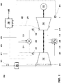
- a gas turbine 10 which comprises a compressor 12, a combustion chamber 20 and a turbine 14, and which is a central component.
- Compressor 12 and turbine 14 are disposed on a common shaft 16 which drives a generator 18.
- the compressor 12 draws air from the environment via an air inlet 28 and a filter 26, compresses it, and forwards the air thus compressed via a plenum to the combustion chamber 20.
- the air mass flow can be regulated via at least one adjustable row of guide vanes 24.
- Part of the compressed air is branched off at the compressor end as cooling air for cooling of life-critical hot-gas components. This high pressure cooling air is used as the combustion chamber cooling air 21 and as the high pressure turbine cooling air 29.
- cooling air can be cool cooled via a cooling air cooler 25 to a cooling air temperature T and be used as recooled cooling air 27 for cooling life-critical hot-gas components.
- the remaining air mass flow is used in the combustion chamber for combustion of a supplied fuel via a fuel supply 22 (liquid or gaseous).
- the resulting hot gas is released in the turbine 14 under work and then can For example, be used in a subsequent heat recovery steam generator for generating process steam or steam for a steam turbine.
- the measurement of the cooling air temperature T cool and the control of the cooling air cooler 25, which may be integrated into the gas turbine governor 30 are not shown.
- a controller 30 For the control of the gas turbine, a controller 30 is provided, which is shown in the figure as a simple block with few signal lines. In reality, however, it can be very complex and can be designed with many inputs / outputs for the different parts of the system.
- the signal line 46 connects the gas turbine controller 30 with the unit controller which controls the unit of the power plant including gas turbine, boiler and water-steam cycle.
- a data line 45 is located between the at least one adjustable vane row 24 and an input of the controller 30. Through this line 45, both the target position of the vanes sent to the actuating mechanism of the VIGV, as well as the measured actual position of the VIGV transmitted to the control.
- the turbine inlet temperature TIT can be ideally measured at the turbine inlet and transmitted via a data line 42 to the controller. In practice, this is not possible due to the high TIT in modern gas turbines, so that the TIT on the pressure ratio of the turbine 14 and the TAT is approached.
- the TAT is measured by a sensor 34 and transmitted via the data line 44 to the controller.
- the pressure be measured before and after the turbine 14.
- the measurement of the suction pressure 31 and the compressor outlet pressure 33, the measured values of which are transmitted to the controller 30 via the data lines 41 and 43, is often approximated to determine the pressure ratio.
- the determination of the TIT from the given measured variables as well as corrections for taking into account further parameters, such as the relative humidity or the VIGV position, are known to the person skilled in the art.
- FIG. 2 Various VIGV full load limits of a gas turbine and TIT full load limit 1 and TIT partial load limit 5 and the associated curve of the turbine inlet temperature TIT and the VIGV relative load P rel in the upper load range are shown. These are shown schematically with solid lines for standard design operation, with dotted lines for efficiency-optimized operation and with dotted lines for performance-optimized operation.
- the operating concept shifts in the upper load range (dotted line).
- the full load will reached full load limit 1 at the same TIT. Due to the lower mass flow, the full load capacity is smaller.
- the TAT not shown here is increased due to the reduced mass flow.
- both the component efficiencies of the gas turbine and thus the gas turbine efficiency and the efficiency of the downstream water steam cycle at the reduced mass flow or the increased exhaust gas temperature are improved, so that the overall efficiency of the power plant is improved. This improvement in efficiency could not be realized by simple load reduction with the standard design operating concept, since after this starting from full load initially the TIT would be reduced, resulting in a reduction in efficiency.
- the operating concept shifts in the upper load range (dot-dash line).
- the full load is reached at the same TIT full load limit 1. Due to the increased mass flow when the VIGV is opened further, the full load capacity increases.
- Fig. 3 the relative efficiency at full load ⁇ rel is shown as a function of the normalized full load power P BL with respect to the full load efficiency under standard design conditions.
- the full load P BL is set by varying the VIGV full load limit.
- the VIGV full-load limit is reduced compared to the standard design limit 2
- the efficiency initially increases because, as described in US Pat Fig. 2 explained, the efficiencies of the individual components at a lower mass flow initially improve. It is thus possible with the VIGV full load limit for efficiency-optimized operation 4 to achieve an improved efficiency compared to the standard design.
- the mass flow reduces the pressure ratio and thus the efficiency of the theoretical process.
- the main components are operated so far away from their design point that component efficiencies no longer increase but drop off again.
- the VIGV full load limit is increased compared to the standard design limit 2, the performance can be increased while accepting a lower efficiency.
- the VIGV can not be opened arbitrarily due to the surge limit of the compressor or the required safety distance to the surge limit or limit of other components.
- the safety margin with respect to the surge limit shall be determined taking into account manufacturing tolerances, possible compressor fouling and the network requirements with respect to underfrequency operation.
- variable VIGV full load limit allows the gas turbine to operate within a range of the Standard Design Limit 2, which is limited by the safety margin to the surge limit of the compressor or limits of other components and the optimum efficiency.
- Fig. 4 The limits and the progression of TIT and VIGV (solid lines) are shown for a life-optimized operating concept in the upper load range.
- the limits of the standard design operating concept in the upper load range and the corresponding course of TIT and VIGV over load are shown as a dotted line as a reference.
- a reduced TIT full-load limit 6 and a full-load limit 2 will be set at VIGV full-load limit 2 reduced TIT partial load limit 7 introduced. Due to the reduced TIT, a lower full load capacity is achieved at the same full load mass flow. The corner point at which the TIT partial load limit 7 is reached starting from full load is likewise shifted to a lower load in accordance with the reduced limits. Accordingly, the VIGV begins to close at lower loads. It may also be necessary to lower the TAT limit to increase life at low part load.
- the TIT and TAT Limits can not be reduced arbitrarily to increase their service life. If the limits are greatly reduced, combustion can become unstable and extinguishing pulsations and / or increased emissions occur. In addition to the gas turbine, the limits of the connected water and steam circuit including the boiler must also be taken into account. If the resultant TAT deviates too much from the design point, the efficiency of the water-steam circuit drops sharply, so that operation becomes unprofitable despite an increased service life.
- a reduction of the NOx emissions can be achieved by reducing at least the TIT full load limit 1. Furthermore, an increase in performance can be achieved by increasing the limit while reducing the service life.
- Fig. 5 The limits and the course of TIT, TAT and VIGV (solid lines) are shown in a CO optimized operating concept. In addition, the limits of the standard design operating concept and the corresponding course of TIT and VIGV over load are shown as a dotted line as a reference.
- premix burners optimized for low NOx emissions at full load temperature may experience increased CO at part load operation with reduced TIT Emissions come. This is usually no problem with the standard design concept.
- the TIT partial load limit not only has the TIT partial load limit been increased, but also the TAT partial load limit has been raised from the standard TAT partial load limit 9 to the TAT partial load limit for CO-optimized operation 11. Without this increase, the same TIT would be used in the low part load range as with the standard operating concept, and the same emissions would be expected accordingly. Depending on the design and requirements, it makes sense to raise only one of the two limits TIT partial load or TAT partial load for a CO optimized operating concept.
- the cooling air temperature T cool is limited, and the cooling capacity of the at least one cooling air cooler regulated so that the limit of the cooling air temperature T cool is not exceeded.
- the cooling air temperature T cool influences the lifetime of critical hot-gas components, but on the other hand it can influence the overall efficiency of the power plant, depending on the integration of the cooler in the overall power plant and the utilization of the heat extracted in the cooler.
- a power plant is usually optimized so that lowering the cooling air temperature T cool below the standard design limit results in a loss of efficiency. By accepting the loss of efficiency, however, it is possible, for example, to reduce the lifetime penalty of an increased TIT.
- the limit of the cooling air temperature T cool is thus another parameter for flexibility and optimization of the operating concept.
- the limits for TIT, TAT, cooling air temperature T cool or other limits of different operating concepts are not necessarily constant values. They can be controlled as a function of load, VIGV or other parameter depending on requirements.
- the operating concepts are also not limited to the examples shown. They can be combined or expanded in different ways. For example, a service life-optimized operating concept with reduced TIT full-load limit 6 and reduced TIT partial-load limit 7 can be combined with the various VIGV limits for performance-optimized 3 or efficiency-optimized 4 operation.
- the cornerstones in the Fig. 2 . 4 and 5 in which the control changes eg from VIGV control to TIT control, are not firmly bound to a relative load. They can shift depending on the ambient conditions, in particular the compressor inlet temperature and pressure and the state of the gas turbine. For example, each power plant ages, which leads to a reduction in performance, so that even with otherwise identical boundary conditions, the corner points can shift in the direction of lower load.
- multiple sets of limits belonging to different lifetime factors may be selected. These may, for example, allow the operator or operator to operate the plant with standard service life, with a lifetime increased by 30%, 50% or 100%, or, alternatively, with a service life reduced by 30% or 50%.
- the operator or operator may specify the desired life within a desired frame, and the TIT and / or TAT limits are adjusted in response to that target life.
- the flexible mode of operation allows operation optimized for efficiency and service life as well as the provision of a significant power reserve.
- a power plant is operated in normal operation, for example, only about 90% of its full load capacity. This has the consequence that it is typically operated at partial load with reduced efficiency compared to the design.
- the flexible adaptation of the operating concept according to the invention makes it possible for such a power plant not only to avoid the loss of efficiency due to partial load operation, but also to realize an improvement in the efficiency with the efficiency-optimized operating concept.
- the required power reserve can ideally be demonstrated by adjusting the TIT and VIGV limits.
- a so-called “spinning reserve” can also be sold.
- a “Spinning Reserve” is usually referred to the capacity, which delivered within 10 minutes in addition to the network can be delivered continuously for at least 2 hours. In such a network, it makes sense to operate the power plant with efficiency-optimized or life-optimized operating concept and sell the possible additional power, which can be realized by adjusting the limits, as a "spinning reserve".
- the invention is not limited to the illustrated operating concepts and their combinations. It is analogous to other operating concepts, such as. to an operating concept for gas turbines with sequential combustion or operating concepts without a partial load reduction of the TIT or concepts that provide additional gradings of different limits.
Description
Die vorliegende Erfindung bezieht sich auf das Gebiet der Kraftwerkstechnik und betrifft ein Verfahren zum optimierten Betrieb einer Gasturbine in einem Kraftwerk in Bezug auf Leistung, Wirkungsgrad, Emissionen und/ oder Lebensdauerverbrauch. Im Rahmen der Erfindung liegt auch ein Kraftwerk zur Durchführung des Verfahrens.The present invention relates to the field of power plant technology and relates to a method for optimized operation of a gas turbine in a power plant in terms of power, efficiency, emissions and / or lifetime consumption. Within the scope of the invention is also a power plant for carrying out the method.
Ein Verfahren zur Regelung einer Gasturbine, das dem Betreiber oder Operator den sicheren Betrieb eines Gasturbinenkraftwerkes erlaubt, wird gewöhnlich als Betriebskonzept oder Fahrkonzept bezeichnet. Die Erfindung bezieht sich auf die Optimierung des Lastbetriebs, d.h. des Teils eines Betriebskonzeptes, der den Betrieb, an dem die Gasturbine mit einem elektrischen Netz verbunden ist und an dies Leistung abgibt, regelt. In dem Betriebskonzept wird festgelegt, wie verschiedene Parameter der Gasturbine zum sicheren Betrieb der Gasturbine geregelt werden müssen. Das Betriebskonzept wird durch den Regler umgesetzt. Die Leistung einer Gasturbine kann beispielsweise durch Veränderung der mindestens einen Turbineneintrittstemperatur, des Verdichter-Eintrittsmassenstromes oder beider Parameter eingestellt werden. Zur Einstellung des Verdichter-Eintrittsmassenstroms kann beispielsweise die Eintrittsgeometrie des Verdichters über ein verstellbares Vorleitgitter verändert werden.A method of controlling a gas turbine that allows the operator or operator to safely operate a gas turbine power plant is commonly referred to as an operational concept or driving concept. The invention relates to the optimization of the load operation, ie the part of an operating concept, which regulates the operation, at which the gas turbine is connected to an electrical network and delivers to this power. In the operating concept it is determined how different parameters of the gas turbine have to be regulated for safe operation of the gas turbine. The operating concept is implemented by the controller. The power of a gas turbine can be adjusted for example by changing the at least one turbine inlet temperature, the compressor inlet mass flow or both parameters. For adjusting the compressor inlet mass flow, for example, the Entry geometry of the compressor can be changed via an adjustable Vorleitgitter.
Die Höhe der Turbineneintrittstemperatur bestimmt im wesentlichen den Lebensdauerverbrauch bzw. die Länge des Inspektionsintervalls der Gasturbine. Sie bestimmt darüber hinaus im wesentlichen die Abgasemissionen der Gasturbine.The height of the turbine inlet temperature essentially determines the lifetime consumption or the length of the inspection interval of the gas turbine. It also essentially determines the exhaust gas emissions of the gas turbine.
Die Leistung einer Gasturbine wird bei konstantem Eintrittsmassenstrom im wesentlichen durch die Höhe der Turbineneintrittstemperatur bestimmt. Die Gasturbinenaustrittstemperatur ist proportional zur Höhe der Turbineneintrittstemperatur und umgekehrt proportional zum Druckverhältnis der Gasturbine.The power of a gas turbine is determined at a constant inlet mass flow substantially by the height of the turbine inlet temperature. The gas turbine exit temperature is proportional to the height of the turbine inlet temperature and inversely proportional to the pressure ratio of the gas turbine.
Der Wirkungsgrad eines kombinierten Gas-Dampfturbinen-Kraftwerks, eines sogenannten Kombikraftwerks, ist proportional zur Höhe der Gasturbinenaustrittstemperatur und dem Gasturbinenwirkungsgrad. Daraus folgt, dass der Gesamtwirkungsgrad und die Leistung eines Kombi-Kraftwerks proportional zur Gasturbineneintrittstemperatur ist.The efficiency of a combined cycle power plant, a so-called combined cycle power plant, is proportional to the magnitude of the gas turbine exit temperature and gas turbine efficiency. It follows that the overall efficiency and power of a combined cycle power plant is proportional to the gas turbine inlet temperature.
Der Wirkungsgrad der Gasturbine wird im theoretischen Brayton Cycle bei konstanter Turbineneintrittstemperatur und konstanten Komponentenwirkungsgraden proportional zum Druckverhältnis. In der realen Maschine ist das Druckverhältnis bei konstanter Turbineneintrittstemperatur proportional zum Massenstrom. Real ändern sich jedoch die Komponentenwirkungsgrade als Funktion von Massenstrom und Temperatur. Insbesondere der Kompressorwirkungsgrad ist von dem Massenstrom, der durch die Vorleitreihenstellung geregelt wird, abhängig. Weiter sind beispielsweise Verluste von Eintritten und Austritten oder Diffusoren eine Funktion des Volumen- bzw. Massenstromes. Entsprechendes gilt für den Kessel, dessen Druckverlust für die ihn durchströmenden Heissgase sowie den angeschlossen Wasser- Dampf- Kreislauf. Die Auslegung der Komponenten auf einen Massenstrom hat zur Folge, dass der Wirkungsgrad einer realen Gasturbine und eines realen Gasturbinenkombikraftwerkes nicht proportional zum Druck oder Massenstrom ansteigt, sondern ein Maximum hat. Wird der Massenstrom und damit das Druckverhältnis über dies Maximum angehoben, so sinkt der Wirkungsgrad. Eine Leistungssteigerung des Kraftwerkes über den Betriebspunkt mit Wirkungsgradmaximum hinaus ist in der Regel möglich.The efficiency of the gas turbine is proportional to the pressure ratio in the theoretical Brayton cycle with constant turbine inlet temperature and constant component efficiencies. In the real machine, the pressure ratio at constant turbine inlet temperature is proportional to the mass flow. Real, however, the component efficiencies change as a function of mass flow and temperature. In particular, the compressor efficiency is dependent on the mass flow, which is controlled by the Vorleitreihenstellung. Further, for example, losses of inlets and outlets or diffusers are a function of the volume or mass flow. The same applies to the boiler, the pressure loss for the flowing through him hot gases and the connected water-steam cycle. The design of the components to a mass flow has the consequence that the efficiency of a real gas turbine and a real gas turbine combined cycle power plant does not increase in proportion to the pressure or mass flow, but has a maximum. If the mass flow and thus the pressure ratio is raised above this maximum, the efficiency drops. An increase in output of the power plant beyond the operating point with maximum efficiency is generally possible.
Moderne Gasturbinen werden im oberen Lastbereich, bei einer Lastabsenkung ausgehend von Volllast (oder Baseload) beispielsweise so geregelt, dass zunächst die Turbineneintrittstemperatur (oder Heissgastemperatur), die durch einen Limiter begrenzt ist, reduziert wird. Entsprechend wird der Limiter von Volllastwert auf den Teillastwert reduziert. Anschliessend wird der Ansaugmassenstrom durch eine Regelung des Anstellwinkels mindestens einer verstellbaren Leitschaufelreihe VIGV des Verdichters, der ihrerseits durch ein Limit begrenzt ist, reduziert. Während der Reduktion des Ansaugmassenstromes wird der Brennstoffmassenstrom reduziert, um die Turbineneintrittstemperatur unterhalb des jeweils anzuwendenden Limits zu regeln. Sobald die Turbinenaustrittstemperatur TAT, die bei konstanter Turbineneintrittstemperatur TIT umgekehrt proportional zu dem mit dem abnehmenden Massenstrom sinkenden Druckverhältnis steigt, den relevanten TAT- Limitwert erreicht hat, wird der Brennstoffmassenstrom reduziert, um die TAT unterhalb des Limits zu regeln. Die TIT fällt dann unter ihr Limit. Das Beispiel eines Betriebskonzeptes für eine moderne Gasturbine mit sequentieller Verbrennung ist in der
Zum Betrieb einer Gasturbine nach dem in der
Ein Beispiel für die Bestimmung der TIT ist in der
Der Erfindung liegt die Aufgabe zugrunde, ein Betriebskonzept genanntes Verfahren zur Regelung eines auf einer Gasturbine basierenden Kraftwerks zu schaffen, welches auch ohne Neuinbetriebnahme eine flexible Anpassung des Verfahrens an sich ändernde Optimierungsziele erlaubt.
Die erfindungsgemässe Lösung der Aufgabe wird dadurch bewerkstelligt, dass verschiedene Limite, die das Betriebskonzept einer Gasturbine bestimmen, wie z.B. Limite der Turbineneintrittstemperatur und/oder der Winkel mindestens einer Verdichtervorleitreihe, durch den Kraftwerksoperator während des Betriebes den Erfordernissen angepasst werden können.The invention has for its object to provide an operating concept called method for controlling a gas turbine based power plant, which allows a flexible adaptation of the method to changing optimization goals even without restarting.
The inventive solution of the problem is accomplished by different limits that determine the operating concept of a gas turbine, such as For example, limit the turbine inlet temperature and / or the angle of at least one Verdichtervorleitreihe, can be adjusted by the power plant operator during operation of the requirements.
Herkömmlich werden die Hauptregelparameter, wie Turbineneintrittstemperatur TIT, Turbinenaustrittstemperatur TAT und der Winkel mindestens einer Verdichtervorleitreihe VIGV innerhalb fester Limite geregelt. Zum Schutz gegen zu hohe Temperaturen oder Volumenströmen, deren Überschreiten schnell zu schweren Schäden an dem Kraftwerk führen würde, sind diese Parameter mit mehrfach redundanten Messungen geschützt. Dabei sind mit einem definierten Sicherheitsabstand zu den Limiten der Regelungen Schutzaktionen wie Schnellabschalten oder Trip der Gasturbine in der Regelung implementiert.Conventionally, the main control parameters, such as turbine inlet temperature TIT, turbine outlet temperature TAT and the angle of at least one compressor precompression series VIGV are regulated within fixed limits. To protect against excessively high temperatures or volume flows whose exceeding would quickly lead to severe damage to the power plant, these parameters are protected with multi-redundant measurements. Protective actions such as rapid shutdown or trip of the gas turbine are implemented in the regulation with a defined safety distance to the limits of the regulations.
Bei der Anpassung von schutzrelevanten Limiten, wie der TIT, TAT oder der VIGV, muss sichergestellt sein, dass die Schwellwerte, an denen Schutzaktionen ausgelöst werden, entsprechend den Änderungen der Limite mit angepasst werden oder so definiert sind, dass sie einen zuverlässigen Schutz im Rahmen der möglichen Variationen der Limitwerte sicherstellen.When adapting protection-relevant limits, such as the TIT, TAT or the VIGV, it must be ensured that the thresholds at which protection actions are triggered are adjusted in accordance with the changes to the limits or are defined in such a way that they provide reliable protection within the framework ensure the possible variations of the limit values.
Das erfindungsgemässe Verfahren gibt dem Kraftwerkbetreiber die Möglichkeit, die Stromgestehungskosten jederzeit gemäss den Anforderungen zu minimieren.The inventive method gives the power plant operator the ability to minimize the cost of electricity at any time according to the requirements.
Die Stromgestehungskosten hängen im wesentlichen von den durch den Betrieb eines Kraftwerks entstehenden Kosten und Erlösen ab. Kosten sind in erster Linie die vom Kraftwerk zu zahlenden Brennstoffkosten, deren Höhe durch den Nettowirkungsgrad des Kraftwerkes bestimmt wird, den Kosten für Wartung und Instandhaltung des Kraftwerkes, Personalkosten, gegebenenfalls Emissionsabgaben sowie Kapitalkosten, Lizenzkosten und Gebühren für Betriebsgenehmigungen. Erlöse erzielt das Kraftwerk durch den Verkauf der elektrischen Leistung, bei sogenannter "Co-Generation" durch Prozessdampf und Wärme sowie für die Bereitstellung von Leistungsreserven an das Netz.The cost of electricity depends essentially on the costs and revenues of operating a power plant. Costs are primarily the fuel costs to be paid by the power plant, the amount of which is determined by the net efficiency of the power plant, the cost of maintenance and repair of the power plant, personnel costs, any emissions levies and capital costs, license costs and operating license fees. The power station achieves sales through the sale of the electric power, in so-called "co-generation" by process steam and heat and for the provision of power reserves to the grid.
Das erfindungsgemässe flexible Gasturbinenbetriebskonzept ermöglicht eine Optimierung des Betriebes hinsichtlich Minimierung der Stromgestehungskosten. Hierbei kann während des Betriebs zwischen verschiedenen, das Betriebskonzept des Kraftwerkes bestimmenden, Limiten bei konstanter oder sich ändernder Leistungserzeugung variiert werden. Insbesondere werden die Volllast- und Teillastlimite für die mindestens eine TIT, die Volllast- und Teillastlimite für die mindestens eine TAT sowie das Limit der VIGV Position variiert. Diese Variation der Limite kann beispielsweise der Kraftwerksoperator durch die Auswahl verschiedener Betriebsweisen an der Leitwarte des Kraftwerkes oder der Gasturbine realisieren. Für eine bedienerfreundliche Regelung muss der Operator nicht einzelne Limite anpassen, sondern kann an der Leitwarte verschiedene Betriebsweisen anwählen und der Regler arbeitet dann automatisch mit dem entsprechenden Satz von Limiten. Dies kann z.B. ein wirkungsgradoptimierter Betrieb, ein Betrieb für maximale Leistung, ein Betrieb mit reduzierten NOx Emissionen, ein Betrieb mit reduzierten Teillast CO Emissionen, ein Betrieb mit verlängerten Wartungsintervallen oder eine Kombination von Optimierungszielen sein. Wege zur Realisierung dieser Betriebsweisen werden anhand der nachfolgenden Ausführungsbeispiele aufgezeigt.The flexible gas turbine operating concept according to the invention makes it possible to optimize the operation with regard to minimizing the cost of electricity generation. This can be varied during operation between different, the operating concept of the power plant defining limits with constant or changing power generation. In particular, the full load and part load limits for the at least one TIT, the full load and part load limits for the at least one TAT and the limit of the VIGV position are varied. For example, the power plant operator can realize this variation of the limits by selecting different modes of operation at the control station of the power plant or the gas turbine. For a user-friendly control, the operator does not need to adjust individual limits, but can select different modes of operation at the control room and the controller then automatically operates with the appropriate set of limits. This can e.g. efficiency-optimized operation, operation for maximum performance, operation with reduced NOx emissions, operation with reduced partial load CO emissions, operation with extended maintenance intervals, or a combination of optimization goals. Ways to implement these modes of operation will be shown with reference to the following embodiments.
Der Kraftwerksoperator kann über eine Eingabe an einem geeigneten Mensch-Maschine Interface, typischerweise der sogenannten Operator Station oder dem Kontrollrechner oder Regler des Kraftwerks, durchführen. Eine Eingabe über eine Leitwarte eines Verbundes von Kraftwerken oder von dem Netzbetreiber ist ebenfalls möglich. Die Optimierungsziele können auch von äussern Bedingungen abhängig definiert werden. Beispielsweise können die Optimierungsziele abhängig von der Jahreszeit vorgegeben sein. Beispielsweise kann es Vorteilhaft sein, das Kraftwerk im
Sommer leistungsoptimiert zu fahren, um den bei Gasturbinen typischen Leistungsrückgang bei hohen ambienten Temperaturen so weit wie möglich auszugleichen und im Winter wirkungsgradoptimiert zu fahren. Unter einem Operator, auch als Fahrer, Leiter oder Führer bezeichnet, hier sind die Personen zu verstehen, die den Betrieb des Kraftwerkes direkt oder indirekt steuern oder überwachen.The power plant operator can perform an input to a suitable man-machine interface, typically the so-called operator station or the control computer or controller of the power plant. An input via a control room of a network of power plants or by the network operator is also possible. The optimization goals can also be defined depending on external conditions. For example, the optimization goals can be predetermined depending on the season. For example, it may be advantageous to use the power plant
To optimize the performance of the summer in order to compensate as much as possible for the gas turbine's typical power decline at high ambient temperatures and to optimize efficiency in winter. Under an operator, also referred to as a driver, leader or leader, here are the persons who control or monitor the operation of the power plant directly or indirectly.
Alle erläuterten Vorteile sind nicht nur in den jeweils angegebenen Kombinationen, sondern auch in anderen Kombinationen, in Kombination mit der Regelung weiterer Parameter oder in Alleinstellung verwendbar, ohne den Rahmen der Erfindung zu verlassen.All the advantages explained are usable not only in the respective combinations indicated, but also in other combinations, in combination with the regulation of further parameters or in isolation, without departing from the scope of the invention.
Neben dem Verfahren ist eine Gasturbine zur Durchführung des Verfahrens Gegenstand der Erfindung. Je nach gewähltem Verfahren oder Kombination von Verfahren muss die Auslegung der Gasturbine angepasst werden, um die Durchführbarkeit des Verfahrens zu gewährleisten.In addition to the method, a gas turbine for carrying out the method is the subject of the invention. Depending on the chosen method or combination of procedures, the design of the gas turbine must be adapted to ensure the feasibility of the process.
Die Kühlluftdruckverhältnisse ändern sich bei Gasturbinen abhängig von den Kompressoreintrittbedingungen und dem Betriebszustand. Ausserdem sind sie von der VIGV- Stellung abhängig. Die Kühlluftdruckverhältnisse von vor dem Kompressorende aus dem Kompressor entnommener Kühlluft sinken dabei typischerweise mit Schliessen der VIGV. Um einen sicheren Betrieb zu gewährleisten, sind die Druckverhältnisse beispielsweise so eingestellt, dass sie für den Volllastbetrieb mit der zugehörigen TIT eine ausreichende Kühlung im gesamten ambienten Betriebsbereich gewährleisten. Ausserdem muss für Teillast gewährleistet sein, dass das mit schliessen der VIGV bei Teillast abnehmende Kühlluftdruckverhältnis noch für eine von Teillast TIT abhängige ausreichende Kühlung sorgt.The cooling air pressure conditions change in gas turbines depending on the compressor inlet conditions and the operating condition. In addition, they depend on the VIGV position. The cooling air pressure ratios of cooling air removed from the compressor before the end of the compressor typically drop when the VIGV is closed. To ensure safe operation, the pressure ratios are set, for example, so that they ensure sufficient cooling in the entire ambient operating range for full-load operation with the associated TIT. In addition, it must be ensured for partial load that the cooling air pressure ratio decreasing with partial closure of the VIGV still ensures adequate cooling dependent on partial load TIT.
In der Regel werden Gasturbinen mit einem Standard Betriebskonzept entsprechenden Kühlluftdruckverhältnissen ausgelegt. Bei der Auslegung wird ausserdem beispielsweise eine Druckmarge vorgesehen, um Fertigungstoleranzen und andere Unsicherheiten ausgleichen zu können. Während der Inbetriebnahme wird dann, beispielsweise über Blenden, das richtige Druckverhältnis eingestellt.As a rule, gas turbines are designed with a standard operating concept corresponding cooling air pressure ratios. In the interpretation, for example, a pressure margin is also provided to compensate for manufacturing tolerances and other uncertainties can. During commissioning, the correct pressure ratio is then set, for example via shutters.
Bei herkömmlichen Gasturbinen wird diese Auslegung und Einstellung für ein Standard Betriebskonzept durchgeführt. Die erfindungsgemässe Gasturbine zeichnet sich dadurch aus, dass sie für mindestens die in dem jeweiligen Kraftwerk geplanten Variationen der Limite und der sich daraus ergebenden Betriebskonzepte ausgelegt ist. Ausserdem sind die Druckverhältnisse bei Inbetriebnahme entsprechend der geplanten Variationen der Limite und der sich daraus ergebenden Betriebskonzepte, z.B. durch Blenden, eingestellt.In conventional gas turbines, this design and setting for a standard operating concept is performed. The gas turbine according to the invention is characterized in that it is designed for at least the variations of the limits planned in the respective power plant and the operating concepts resulting therefrom. Moreover, the pressure ratios at start-up are in accordance with the planned variations of the limits and the consequent operating concepts, e.g. through apertures, set.
Gemäss einer weiteren Ausgestaltung sind die Systeme des Kraftwerkes so ausgelegt, dass sie einen dem Betriebskonzept entsprechenden verlängerten Wartungsintervall zulassen.According to a further embodiment, the systems of the power plant are designed so that they allow a prolonged maintenance interval corresponding to the operating concept.
Um die Wahl von leistungsoptimierten Limiten zu erlauben, sind die elektrischen Systeme, d.h. auch Generatoren und Transformatoren so auszulegen, dass die maximale Kraftwerksleistung, die im Rahmen der spezifischen Limite erreichbar ist, an das Netz abgegeben werden kann. Entsprechend muss auch das Brennstoffsystem für den maximal möglichen Brennstoffmassenstrom ausgelegt werden.To allow the choice of power-optimized limits, the electrical systems, i. also to design generators and transformers so that the maximum power plant output achievable within the specific limits can be delivered to the grid. Accordingly, the fuel system must be designed for the maximum possible fuel mass flow.
Weiter sind in dem Regler und/ oder der zugehörigen Speichereinheit die verschiedenen Sätze von Limitwerten entsprechend der vorgesehenen Betriebskonzepte abgelegt, so dass zwischen den Limiten umgeschaltet werden kann.Furthermore, the various sets of limit values corresponding to the intended operating concepts are stored in the controller and / or the associated memory unit, so that it is possible to switch between the limits.
Bei einem Kombikraftwerk ist ausserdem der Wasser-Dampfkreislauf inklusive Kessel für alle möglichen Variation der TAT und des Abgasmassenstromes, die sich aus den verschieden für das Kraftwerk vorgesehen Limitkombination des Gasturbinebetriebskonzeptes ergeben, auszulegen.In a combined cycle power plant is also the water-steam cycle including boiler for all possible variation of the TAT and the exhaust gas mass flow, resulting from the different for the power plant intended limit combination of the gas turbine operating concept interpreted.
Weitere Vorteile, Merkmale und Einzelheiten der Erfindung ergeben sich aus der nachfolgenden Betrachtung bevorzugter Ausführungsbeispiele sowie anhand der Zeichnungen; diese zeigen schematisch in
- Fig. 1
- ein vereinfachtes Blockschaltbild für ein Kraftwerk mit einer Gasturbine;
- Fig. 2
- die verschiedenen VIGV Volllast- Limite einer Gasturbine und der zugehörige Verlauf der Turbineneintrittstemperatur über Last im oberen Lastbereich;
- Fig. 3
- den relativen Wirkungsgrad bei Volllast ηrel als Funktion der normierten Volllastleistung PBL bezogen auf den Volllastwirkungsgrad bei Standard Design Bedingungen, wobei die Leistung PBL durch Variation des VIGV Volllast Limits eingestellt wird;
- Fig. 4
- TIT Volllast und TIT Teillast Limite einer Gasturbine für Standard Design und lebensdaueroptimiertes Betriebskonzept und der zugehörige Verlauf der VIGV- Stellung und TIT über Last im oberen Lastbereich; und
- Fig. 5
- TIT- und TAT Teillast- Limite für CO- Emissionsoptimierten Betrieb im Vergleich zu den Limiten im lebensdaueroptimierten Betrieb sowie der zugehörige Verlauf der VIGV- Stellung und TIT über Last im oberen Lastbereich.
- Fig. 1
- a simplified block diagram for a power plant with a gas turbine;
- Fig. 2
- the various VIGV full load limits of a gas turbine and the associated curve of the turbine inlet temperature over load in the upper load range;
- Fig. 3
- the relative efficiency at full load η rel as a function of the normalized full load power P BL with respect to the full load efficiency under standard design conditions, setting the power P BL by varying the VIGV full load limit;
- Fig. 4
- TIT full load and TIT partial load Limitation of a gas turbine for standard design and life-optimized operating concept and the associated course of the VIGV position and TIT via load in the upper load range; and
- Fig. 5
- TIT and TAT partial load limits for CO- emission-optimized operation compared to the limits in life-optimized operation as well as the corresponding course of the VIGV position and TIT over load in the upper load range.
Bei einem in
Für die Regelung der Gasturbine ist ein Regler 30 vorgesehen, der in der Figur als einfacher Block mit wenigen Signalleitungen dargestellt ist. Er kann in der Realität jedoch sehr komplex und mit vielen Ein/ Ausgängen für die verschiedenen Anlagenteile ausgestaltet sein kann. Die Signalleitung 46 verbindet den Gasturbinenregler 30 mit dem Unit Regler der die Unit des Kraftwerks inklusive Gasturbine, Kessel und Wasser- Dampfkreislauf regelt.For the control of the gas turbine, a
In einem dem Regler 30 zugeordneten oder in den Regler 30 integrierten Datenspeicher sind verschiedene Sätze von Limitwerten, die die VIGV, TIT, TAT und Kühllufttemperatur Tcool für Teillast und Volllast begrenzen, abgelegt.In a data memory associated with the
Zur Regelung der Gasturbine 10 werden grundlegende Prozessgrössen herangezogen, und zwar insbesondere der Anstellwinkel VIGV der mindestens einen verstellbaren Leitschaufel 24 des Verdichters 12 und die Turbineneintrittstemperatur TIT am Eingang der Turbine 14. Zur Regelung der VIGV ist eine Datenleitung 45 zwischen der mindestens einen verstellbaren Leitschaufelreihe 24 und einem Eingang der Regelung 30 vorgesehen. Über diese Leitung 45 wird sowohl die Soll-Position der Leitschaufeln an den Stellmechanismus der VIGV geschickt, als auch die gemessene Ist-Position der VIGV and die Regelung übertragen. Die Turbineneingangstemperatur TIT kann idealisiert am Turbineneintritt gemessen werden und über eine Datenleitung 42 and den Regler übermittelt werden. Praktisch ist dies Aufgrund der hohen TIT bei modernen Gasturbinen nicht möglich, so dass die TIT über das Druckverhältnis der Turbine 14 sowie die TAT angenährt wird. Die TAT wird über einen Sensor 34 gemessen und über die Datenleitung 44 an den Regler übertragen. Zur Bestimmung des Turbinendruckverhältnisses kann der Druck vor und nach der Turbine 14 gemessen werden. In der Praxis wird zur Bestimmung des Druckverhältnisses oft vereinfachend die Messung des Ansaugdruckes 31 und des Verdichteraustrittsdruckes 33, deren Messwerte über die Datenleitungen 41 und 43 an den Regler 30 übermittelt werden angenährt. Die Bestimmung der TIT aus den angegebenen Messgrössen sowie Korrekturen zur Berücksichtigung weiterer Parameter, wie z.B. der relativen Luftfeuchtigkeit oder der VIGV Stellung, sind dem Fachmann bekannt.For controlling the gas turbine 10, basic process variables are used, in particular the angle of attack VIGV of the at least one
In
Der Einfluss der Limite auf das Betriebskonzept wird für eine Lastreduktion ausgehend von Volllast erläutert. Für Standard Design Betrieb (durchgezogene Linie), bei dem die VIGV am VIGV Volllastlimit für Standard Design Betrieb 2 und die TIT am Volllastlimit für Standard Design Betrieb 1 sind, wird zunächst die TIT über die Brennstoffmassenstrom geregelt reduziert bis bei hoher Teillast das TIT Teillastlimit für Standard Design Betrieb 5 erreicht wird. Die VIGV bleibt während dieser Lastabsenkung konstant offen am VIGV Volllastlimit für Standard Design Betrieb 2. Sobald das TIT Teillastlimit für Standard Design Betrieb 5 erreicht wird, wird die TIT konstant gehalten und die Last über die VIGV Position geregelt. Die TIT wird dabei über den Brennstoffmassenstrom konstant auf dem TIT Teillastlimit für Standard Design Betrieb 5 geregelt.The influence of the limits on the operating concept is explained for a load reduction from full load. For standard design operation (solid line) where the VIGV at the VIGV full load limit for
Wird das VIGV Volllastlimit zur Reduktion des maximalen Massenstroms auf das Limit für den wirkungsgradoptimierten Betrieb 4 verkleinert, verschiebt sich das Betriebskonzept im oberen Lastbereich (gepunktete Linie). Die Volllast wird bei dem selben TIT Volllastlimit 1 erreicht. Aufgrund des geringeren Massenstroms wird die Volllastleistung kleiner. Die hier nicht dargestellte TAT ist aufgrund des reduzierten Massenstroms erhöht. In dem dargestellten Beispiel sind sowohl die Komponentenwirkungsgrade der Gasturbine und damit der Gasturbinenwirkungsgrad als auch der Wirkungsgrad des nachgeschalteten Wasser- Dampfkreislaufes bei dem reduzierten Massenstrom bzw. der erhöhten Abgastemperatur verbessert, so das der Gesamtwirkungsgrad des Kraftwerkes verbessert wird. Diese Verbesserung im Wirkungsgrad liesse sich durch einfache Lastreduktion mit dem Standard Design Betriebskonzept nicht realisieren, da nach diesem ausgehend von Volllast zunächst die TIT reduziert würde, was eine Wirkungsgradreduktion mit sich bringt.If the VIGV full load limit for reducing the maximum mass flow is reduced to the limit for efficiency-optimized
Wird das VIGV Vollastlimit zur Erhöhung des maximalen Massenstroms auf das Limit für den leistungsoptimierten Betrieb 3 vergrössert, verschiebt sich das Betriebskonzept im oberen Lastbereich (strichpunktierte Linie). Die Volllast wird bei dem selben TIT Volllastlimit 1 erreicht. Aufgrund des erhöhten Massenstroms bei weiter geöffneter VIGV wird die Volllastleistung grösser.If the VIGV full load limit for increasing the maximum mass flow is increased to the limit for performance-optimized
In
Wird in dem gezeigten Beispiel das VIGV Volllast- Limit gegenüber dem Standard Design Limit 2 reduziert, so steigt zunächst der Wirkungsgrad, da sich, wie unter
Wird das VIGV Volllastlimit Limit weiter Reduziert, sinkt mit dem Massenstrom das Druckverhältnis und damit der Wirkungsgrad des theoretischen Prozesses. Ausserdem werden die Hauptkomponenten so weit entfernt von ihrem Designpunkt betrieben, dass die Komponentenwirkungsgrade nicht mehr ansteigen sonder auch wieder abfallen.If the VIGV full load limit is further reduced, the mass flow reduces the pressure ratio and thus the efficiency of the theoretical process. In addition, the main components are operated so far away from their design point that component efficiencies no longer increase but drop off again.
Wird in dem gezeigten Beispiel das VIGV Volllast- Limit gegenüber dem Standard Design Limit 2 erhöht, lässt sich die Leistung unter Inkaufnahme eines geringeren Wirkungsgrades erhöhen. Je weiter das VIGV Volllast- Limit vergrössert wird, desto steiler fällt der Wirkungsgrad, so dass die Möglichkeit das VIGV Volllast- Limit 3 zu erhöhen, begrenzt ist. Ausserdem kann die VIGV aufgrund der Pumpgrenze des Verdichters bzw. des erforderlichen Sicherheitsabstandes zur Pumpgrenze oder Limite anderer Komponenten nicht beliebig geöffnet werden. Der Sicherheitsabstand gegenüber der Pumpgrenze ist unter Berücksichtigung von Fertigungstoleranzen, möglicher Verdichterverschmutzung sowie der Netzanforderungen in Bezug auf Unterfrequenzbetrieb zu bestimmen.If in the example shown the VIGV full load limit is increased compared to the
Durch das vorgeschlagene variable VIGV Volllast- Limit kann die Gasturbine in einem Bereich um das Standard Design Limit 2, der durch die den Sicherheitsabstande zur Pumpgrenze des Verdichters oder Limite anderer Komponenten und das Wirkungsgradoptimum begrenzt ist, betrieben werden.The proposed variable VIGV full load limit allows the gas turbine to operate within a range of the
In
Zur Realisierung eines lebensdaueroptimierten Betriebskonzepts wird bei unverändertem VIGV Volllastlimit 2 ein reduziertes TIT Volllastlimit 6 und ein reduziertes TIT Teillastlimit 7 eingeführt. Aufgrund der reduzierten TIT wird bei gleichem Volllastmassenstrom eine tiefere Volllastleistung erreicht. Der Eckpunkt, bei dem ausgehend von Volllast das TIT Teillastlimit 7 erreicht wird, ist entsprechend der reduzierten Limits ebenfalls zu einer tieferen Last verschoben. Die VIGV fängt entsprechend auch bei tieferer Last zu schliessen an. Um die Lebensdauer bei tiefer Teillast entsprechend anzuheben, kann es ausserdem erforderlich, sein die TAT Limite abzusenken.In order to realize a service life-optimized operating concept, a reduced TIT full-
Die TIT und TAT Limite können zur Erhöhung der Lebensdauer nicht beliebig reduziert werden. Bei starker Reduktion der Limite kann die Verbrennung instabil werden und es zu Löschpulsationen und/ oder erhöhten Emissionen kommen. Neben der Gasturbine, sind auch die Limite des angeschlossenen Wasser- Dampfkreislaufes inklusive Kessel zu beachten. Bei zu stark vom Auslegungspunkt abweichender resultierender TAT fällt der Wirkungsgrad des Wasser- Dampfkreislaufes stark, so dass der Betrieb trotz erhöhter Lebensdauer unrentabel wird.The TIT and TAT Limits can not be reduced arbitrarily to increase their service life. If the limits are greatly reduced, combustion can become unstable and extinguishing pulsations and / or increased emissions occur. In addition to the gas turbine, the limits of the connected water and steam circuit including the boiler must also be taken into account. If the resultant TAT deviates too much from the design point, the efficiency of the water-steam circuit drops sharply, so that operation becomes unprofitable despite an increased service life.
Analog zur Lebensdauererhöhung kann eine Reduktion der NOx Emissionen durch Reduktion von mindestens dem TIT Volllastlimit 1 erreicht werden. Weiter kann eine Leistungserhöhung durch Erhöhen der Limite bei reduzierter Lebensdauer erreicht werden.Analogous to the service life increase, a reduction of the NOx emissions can be achieved by reducing at least the TIT
In
Je nach Design von Brennkammer und Brenner kann es bei Vormischverbrennern, die für niedrige NOx-Emissionen bei Volllasttemperatur optimiert sind, beim Teillastbetrieb mit reduzierter TIT zu erhöhten CO Emissionen kommen. Dies ist in der Regel bei dem Standard Designbetriebskonzept kein Problem. Für spezifische Anforderungen, wie z.B. sehr niedrige CO Emissionen im Teillastbetrieb, kann es aber Vorteilhaft sein, die Teillast TIT auf einem gegenüber dem Standard angehobenen Niveau zu halten. Dies wird bei hoher Teillast realisiert, indem ein gegenüber dem Standard erhöhtes TIT Teillastlimit für CO-optimierten Betrieb 8 benutzt wird.Depending on the design of the combustor and combustor, premix burners optimized for low NOx emissions at full load temperature may experience increased CO at part load operation with reduced TIT Emissions come. This is usually no problem with the standard design concept. For specific requirements, such as very low CO emissions in part-load operation, it may be advantageous to keep the partial load TIT at a higher level than the standard. This is realized at high part load by using a TIT partial load limit for CO optimized
Bei einer Lastreduktion ausgehend von Volllast, wird das erhöhte TIT Teillastlimits für CO-optimierten Betrieb 8 bei einer höheren Last als bei dem Standard- Betriebskonzept erreicht. Dies führt dazu, dass der Ansaugmassenstrom schon bei höherer Last durch Schliessen der VIGV reduziert wird.With a load reduction starting from full load, the increased TIT partial load limits for
Mit, durch Schliessen der VIGV, abnehmenden Massenstrom steigt bei konstanter Teillast- TIT die Abgastemperatur TAT. Sie wird im Standard Betriebskonzept durch das TAT Teillastlimit 9 begrenzt. Sobald die TAT das TAT Teillastlimit für Standard Design Betrieb 9 erreicht hat wird über den Brennstoffmassenstrom nicht die TIT sondern die TAT geregelt.With, by closing the VIGV, decreasing mass flow increases at constant partial load TIT the exhaust gas temperature TAT. It is limited in the standard operating concept by the TAT
In dem gezeigten Beispiel ist nicht nur das TIT Teillastlimit angehoben, sondern auch das TAT Teillastlimit vom standard TAT Teillastlimit 9 auf das TAT Teillastlimit für CO-optimierten Betrieb 11 angehoben. Ohne diese Anhebung würde im tiefen Teillastbereich mit der selben TIT gefahren, wie mit dem Standard Betriebskonzept und entsprechend wären auch die gleichen Emissionen zu erwarten. Je nach Design und Erfordernissen ist es sinnvoll nur eines der beiden Limite TIT Teillast oder TAT Teillast für ein CO optimiertes Betriebskonzept anzuheben.In the example shown, not only has the TIT partial load limit been increased, but also the TAT partial load limit has been raised from the standard TAT
Bei Gasturbinen mit Kühlluftkühler wird die Kühllufttemperatur Tcool limitiert, und die Kühlleistung des mindestens einen Kühlluftkühlers so geregelt, dass das Limit der Kühllufttemperatur Tcool nicht überschritten wird. Einerseits kann eine Veränderung der Kühllufttemperatur Tcool die Lebensdauer kritischer Heissgasteile beeinflussen, andererseits kann sie, je nach Integration des Kühlers in das Gesamtkraftwerk und Ausnutzung der im Kühler entzogenen Wärme, den Gesamtwirkungsgrad des Kraftwerkes beeinflussen. Dabei ist ein Kraftwerk meist so optimiert, dass eine Absenkung der Kühllufttemperatur Tcool unter das Standard Design Limit zu einer Wirkungsgradeinbusse führt. Unter Inkaufnahme der Wirkungsgradeinbusse kann aber beispielsweise die Lebensdauerpönale einer erhöhten TIT reduziert werden. Das Limit der Kühllufttemperatur Tcool ist somit ein weiterer Parameter zur Flexibilisierung und Optimierung des Betriebskonzeptes.In gas turbines with cooling air cooler , the cooling air temperature T cool is limited, and the cooling capacity of the at least one cooling air cooler regulated so that the limit of the cooling air temperature T cool is not exceeded. On the one hand, one can Changing the cooling air temperature T cool influences the lifetime of critical hot-gas components, but on the other hand it can influence the overall efficiency of the power plant, depending on the integration of the cooler in the overall power plant and the utilization of the heat extracted in the cooler. A power plant is usually optimized so that lowering the cooling air temperature T cool below the standard design limit results in a loss of efficiency. By accepting the loss of efficiency, however, it is possible, for example, to reduce the lifetime penalty of an increased TIT. The limit of the cooling air temperature T cool is thus another parameter for flexibility and optimization of the operating concept.
Die Limite für TIT, TAT, Kühllufttemperatur Tcool oder andere Limite der verschieden Betriebskonzepte sind nicht notwenig konstante Werte. Sie können je nach Anforderungen als Funktion der Last, der VIGV oder eines anderen Parameters geregelt sein. Die Betriebskonzepte sind ausserdem nicht auf die gezeigten Beispiele beschränkt. Sie können in verschiedener Art kombiniert oder erweitert werden. Beispielsweise kann ein lebensdaueroptimiertes Betriebskonzept mit reduziertem TIT Volllastlimit 6 und reduziertem TIT Teillastlimit 7 mit den verschieden VIGV Limits für leistungsoptimierten 3 oder wirkungsgradoptimierten 4 Betrieb kombiniert werden.The limits for TIT, TAT, cooling air temperature T cool or other limits of different operating concepts are not necessarily constant values. They can be controlled as a function of load, VIGV or other parameter depending on requirements. The operating concepts are also not limited to the examples shown. They can be combined or expanded in different ways. For example, a service life-optimized operating concept with reduced TIT full-
Die Eckpunkte in den
Neben einer Absenkung der TIT und/ oder TAT Limite zur Lebensdauerverlängerung ist es oft auch zweckmässig die Möglichkeit einer Erhöhung der Limite zu ermöglichen, damit eine Leistungssteigerung unter Inkaufnahme von Lebensdauerverbrauch ermöglicht wird.In addition to lowering the TIT and / or TAT limits to extend the lifespan, it is often practical to have the option of To increase the limit to enable a performance increase at the expense of lifetime consumption.
In einer Ausführung der Erfindung können mehrere Sätze von Limiten angewählt werden, die zu verschiedenen Lebensdauerfaktoren gehören. Diese können es dem Betreiber oder Operator beispielsweise ermöglichen das Kraftwerk mit Standard- Lebensdauer zu betreiben, mit einer um 30%, 50% oder 100% erhöhten Lebensdauer zu betreiben, oder alternativ mit einer um 30% oder 50% reduzierten Lebensdauer zu betreiben.In one embodiment of the invention, multiple sets of limits belonging to different lifetime factors may be selected. These may, for example, allow the operator or operator to operate the plant with standard service life, with a lifetime increased by 30%, 50% or 100%, or, alternatively, with a service life reduced by 30% or 50%.
In einer weiteren Ausführung der Erfindung kann der Betreiber oder Operator die gewünschte Lebensdauer innerhalb eines gewünschten Rahmens vorgeben und die TIT und/ oder TAT Limite werden in Abhängigkeit von dieser Ziellebensdauer angepasst.In another embodiment of the invention, the operator or operator may specify the desired life within a desired frame, and the TIT and / or TAT limits are adjusted in response to that target life.
Die flexible Betriebsweise erlaubt einen auf Wirkungsgrad und Lebensdauer optimierten Betrieb sowie die Bereitstellung einer signifikanten Leistungsreserve. Abhängig von dem Stromnetz, in das das Kraftwerk Leistung einspeisst, wird ein Kraftwerk im Normalbetrieb beispielsweise nur bei etwa 90% seiner Volllastleistung betrieben. Dies hat zur Folge, dass es bei Teillast typischerweise mit gegenüber der Auslegung reduziertem Wirkungsgrad betrieben wird. Die erfindungsgemässe flexible Anpassung des Betriebskonzeptes erlaubt es für ein derartiges Kraftwerk nicht nur die Wirkungsgradeinbusse durch Teillastbetrieb zu vermeiden, sondern mit dem wirkungsgradoptimierten Betriebskonzept noch eine Verbesserung des Wirkungsgrades zu realisieren. Die erforderliche Leistungsreserve kann idealerweise durch Anpassung der TIT und VIGV Limite demonstriert werden.The flexible mode of operation allows operation optimized for efficiency and service life as well as the provision of a significant power reserve. Depending on the power grid, in which the power plant feeds power, a power plant is operated in normal operation, for example, only about 90% of its full load capacity. This has the consequence that it is typically operated at partial load with reduced efficiency compared to the design. The flexible adaptation of the operating concept according to the invention makes it possible for such a power plant not only to avoid the loss of efficiency due to partial load operation, but also to realize an improvement in the efficiency with the efficiency-optimized operating concept. The required power reserve can ideally be demonstrated by adjusting the TIT and VIGV limits.
Je nach Stromnetz kann ausserdem eine sogenannte "Spinning Reserve" verkauft werden. Als "Spinning Reserve" ist in der Regel die Kapazität bezeichnet, die innerhalb von 10 Minuten zusätzlich an das Netz geliefert werden kann und für mindestens 2 Stunden kontinuierlich abgegeben werden kann. In einem solchen Netz bietet es sich an, das Kraftwerk mit wirkungsgradoptimiertem oder lebensdaueroptimiertem Betriebskonzept zu betreiben und die mögliche Zusatzleistung, die durch Anpassung der Limite realisiert werden kann, als "Spinning Reserve" zu verkaufen.Depending on the power grid, a so-called "spinning reserve" can also be sold. As a "Spinning Reserve" is usually referred to the capacity, which delivered within 10 minutes in addition to the network can be delivered continuously for at least 2 hours. In such a network, it makes sense to operate the power plant with efficiency-optimized or life-optimized operating concept and sell the possible additional power, which can be realized by adjusting the limits, as a "spinning reserve".
Die Erfindung ist nicht auf die dargestellten Betriebskonzepte und ihre Kombinationen beschränkt. Sie ist analog auf andere Betriebskonzepte übertragbar, wie z.B. auf ein Betriebskonzept für Gasturbinen mit sequentieller Verbrennung oder Betriebskonzepte ohne eine Teillastabsenkung der TIT oder Konzepte, die zusätzliche Stufungen der verschiedenen Limite vorsehen.The invention is not limited to the illustrated operating concepts and their combinations. It is analogous to other operating concepts, such as. to an operating concept for gas turbines with sequential combustion or operating concepts without a partial load reduction of the TIT or concepts that provide additional gradings of different limits.
- 11
- TIT Volllast Limit für Standard Design-BetriebTIT full load limit for standard design operation
- 22
- VIGV Volllast Limit für Standard Design-BetriebVIGV full load limit for standard design operation
- 33
- VIGV Volllast Limit für leistungsoptimierten BetriebVIGV full load limit for performance-optimized operation
- 44
- VIGV Volllast Limit für wirkungsgradoptimierten BetriebVIGV full load limit for efficiency-optimized operation
- 55
- TIT Teillast Limit für Standard Design-BetriebTIT Part load limit for standard design operation
- 66
- TIT Volllast Limite für lebensdaueroptimierten BetriebTIT full load limit for life-optimized operation
- 77
- TIT Teillast Limite für lebensdaueroptimierten BetriebTIT partial load limit for life-optimized operation
- 88th
- TIT Teillast Limite für CO-optimierten BetriebTIT Part load limit for CO-optimized operation
- 99
- TAT Teillastlimit für Limite für Standard Design-BetriebTAT partial load limit for limits for standard design operation
- 1010
- Gasturbinegas turbine
- 1111
- TAT Teillastlimit für Limite für CO-optimierten BetriebTAT partial load limit for limits for CO-optimized operation
- 1212
- Verdichtercompressor
- 1414
- Turbineturbine
- 1616
- Wellewave
- 1818
- Generatorgenerator
- 2020
- Brennkammercombustion chamber
- 2121
- BrennkammerkühlluftCombustion chamber cooling air
- 2222
- Brennstoffzufuhrfuel supply
- 2323
- Kühlluftcooling air
- 2424
- verstellbare Leitschaufelreiheadjustable guide blade row
- 2525
- KühlluftkühlerCooling air cooler
- 2626
- Filterfilter
- 2727
- Rückgekühlte KühlluftCooled cooling air
- 2828
- Lufteinlassair intake
- 2929
- Hochdruck- TurbinenkühlluftHigh pressure turbine cooling air
- 3030
- Reglerregulator
- 3131
- Messwertaufnehmer (Kompressoreintrittsbedingungen: Temperatur, Druck und Luftfeuchtigkeit)Transducers (compressor inlet conditions: temperature, pressure and humidity)
- 3232
- Messwertaufnehmer (Turbineneintrittstemperatur TIT)Sensor (turbine inlet temperature TIT)
- 3333
- Messwertaufnehmer (Kompressoraustrittsdruck)Measuring transducer (compressor outlet pressure)
- 3434
- Messwertaufnehmer (Turbinenaustrittstemperatur TAT)Measuring transducer (turbine outlet temperature TAT)
- 4141
- Signalleitung (Kompressoreintrittsbedingungen)Signal line (compressor entry conditions)
- 4242
- Signalleitung (Turbineneintrittstemperatur TIT)Signal line (turbine inlet temperature TIT)
- 4343
- Signalleitung (Kompressorenddruck)Signal line (compressor end pressure)
- 4444
- Signalleitung (Turbinenaustrittstemperatur TAT)Signal line (turbine outlet temperature TAT)
- 4545
- Signalleitung (VIGV Soll-Position und Ist-Position)Signal line (VIGV set position and actual position)
- 4646
- Signalleitung/ Signalaustausch zum Unit KontrollerSignal line / signal exchange to unit controller
- TITTIT
- TurbineneintrittstemperaturTurbine inlet temperature
- TATDID
- TurbinenaustrittstemperaturTurbine outlet temperature
- Tcool T cool
- KühllufttemperaturCooling air temperature
- VIGVVIGV
- Anstellwinkel der verstellbaren LeitschaufelreiheAngle of the adjustable guide blade row
- Prel P rel
- Relative Last bezogen auf die Volllast bei StandardRelative load related to full load at standard
- PBL P BL
- normierten Volllastleistungnormalized full load capacity
- ηrel η rel
- relative Wirkungsgrad bei Volllast ηrel relative efficiency at full load η rel
- BLBL
- Volllastfull load
- PLPL
- Teillastpartial load
Claims (15)
- Method for regulating a gas turbine (10) in a power plant, comprising at least one compressor (12) with an adjustable guide vane row (24), at least one combustion chamber (20) and at least one turbine (14), wherein at least one limit of the operating concept is varied by a power plant operator during operation in order to adapt to optimisation targets of the power plant in relation to power, efficiency, emissions and/or service life consumption, characterised in that at least one cooling air temperature limit of a back-cooled cooling air mass flow (27), which is branched off the compressor (12) for cooling hot gas parts of the turbine (14), is varied.
- Method according to claim 1, characterised in that the at least one limit varied during operation is a protection-relevant limit of the gas turbine.
- Method according to claim 1 or 2, characterised in that at least one full-load limit of the working angle (VIGV) of the at least one adjustable guide vane row (24) of the compressor (12) is varied.
- Method according to claim 3, characterised in that the full-load limit of the working angle (VIGV) of the at least one adjustable guide vane row (24) of the compressor (12) is varied between a maximum limit, defined by the pumping limit reduced by a safety interval, and a minimum limit at which the greatest full-load efficiency is achieved.
- Method according to any of claims 1 to 4, characterised in that at least one full-load limit of the turbine inlet temperature (TIT) and/or at least one part-load limit of the turbine inlet temperature (TIT) is varied.
- Method according to any of claims 1 to 5, characterised in that at least one part-load limit of the turbine outlet temperature (TAT) is varied.
- Method according to any of claims 1 to 6, characterised in that at least one full-load limit of the turbine inlet temperature (TIT) and/or a part-load limit of the turbine inlet temperature (TIT) and/or at least one part-load limit of the turbine outlet temperature (TAT) is reduced relative to the standard design limit in order to extend the service life.
- Method according to any of claims 1 to 6, characterised in that at least one part-load limit of the turbine inlet temperature (TIT) and/or at least one part-load limit of the turbine outlet temperature (TAT) is increased relative to the standard design limit in order to reduce the CO emissions.
- Method according to any of claims 1 to 8, characterised in that at least one limit for providing power reserves is varied relative to the network.
- Power plant configured to perform the method according to any of claims 1 to 10, comprising at least one gas turbine (10) containing at least one compressor (12) with at least one adjustable guide vane row (24), at least one combustion chamber (20) and at least one turbine (14) and at least one regulation system, wherein the power plant comprises a regulator (30) which regulates the various adjustable limits and comprises a man-machine interface for selection of an optimisation target, characterised in that the regulator (30) varies the cooling air temperature limit of the back-cooled cooling air mass flow (27) which is branched off the compressor (12) for cooling hot gas parts of the turbine (14).
- Power plant according to claim 10, characterised in that a minimum cooling air pressure ratio, dependent on the turbine inlet temperature (TIT), is guaranteed for the entire working range of the working angle (VIGV) of the at least one adjustable guide vane row (24) of the compressor (12).
- Power plant according to one of claims 10 or 11, characterised in that at least one boiler is connected downstream of the at least one gas turbine (10), and that this at least one boiler is configured for all exhaust gas mass flows and exhaust gas temperatures (TAT) which may occur due to variation of the operating limits.
- Power plant according to claim 12, characterised in that the at least one steam turbine is designed for converting into energy the maximum steam mass flow produced by the at least one boiler on variation of the operating limits of the gas turbine (10).
- Power plant according to any of claims 10 to 13, characterised in that the electrical systems are configured for the maximum power generated on variation of the operating limits of the gas turbine (10).
- Power plant according to any of claims 10 to 14, characterised in that the fuel systems are configured for the maximum fuel mass flow required on variation of the operating limits of the gas turbine (10).
Applications Claiming Priority (2)
| Application Number | Priority Date | Filing Date | Title |
|---|---|---|---|
| CH3212008 | 2008-03-05 | ||
| PCT/EP2009/051573 WO2009109446A1 (en) | 2008-03-05 | 2009-02-11 | Method for regulating a gas turbine in a power plant and power plant to carry out the method |
Publications (2)
| Publication Number | Publication Date |
|---|---|
| EP2260193A1 EP2260193A1 (en) | 2010-12-15 |
| EP2260193B1 true EP2260193B1 (en) | 2018-08-29 |
Family
ID=39756602
Family Applications (1)
| Application Number | Title | Priority Date | Filing Date |
|---|---|---|---|
| EP09717769.5A Active EP2260193B1 (en) | 2008-03-05 | 2009-02-11 | Method for regulating a gas turbine in a power plant and power plant to carry out the method |
Country Status (4)
| Country | Link |
|---|---|
| US (1) | US8826670B2 (en) |
| EP (1) | EP2260193B1 (en) |
| JP (1) | JP5490023B2 (en) |
| WO (1) | WO2009109446A1 (en) |
Cited By (1)
| Publication number | Priority date | Publication date | Assignee | Title |
|---|---|---|---|---|
| US11525375B2 (en) | 2020-04-09 | 2022-12-13 | General Electric Company | Modeling and control of gas cycle power plant operation with variant control profile |
Families Citing this family (39)
| Publication number | Priority date | Publication date | Assignee | Title |
|---|---|---|---|---|
| FR2942272B1 (en) * | 2009-02-16 | 2011-05-06 | Snecma | METHOD AND SYSTEM FOR CONTROLLING GAS TURBINE AND GAS TURBINE HAVING SUCH A SYSTEM |
| US8370044B2 (en) * | 2009-06-26 | 2013-02-05 | General Electric Company | NOX compliant peak for gas turbine |
| IT1396517B1 (en) * | 2009-11-27 | 2012-12-14 | Nuovo Pignone Spa | METHOD OF MODE CONTROL BASED ON EXHAUST TEMPERATURE FOR GAS TURBINE AND GAS TURBINE |
| TWI593878B (en) * | 2010-07-02 | 2017-08-01 | 艾克頌美孚上游研究公司 | Systems and methods for controlling combustion of a fuel |
| IT1403788B1 (en) * | 2010-12-29 | 2013-10-31 | Ansaldo Energia Spa | METHOD FOR CONTROLLING A COMBINED CYCLE PLANT IN "SINGLE-SHAFT" CONFIGURATION AND COMBINED CYCLE SYSTEM IN "SINGLE-SHAFT" CONFIGURATION |
| CH704381A1 (en) * | 2011-01-24 | 2012-07-31 | Alstom Technology Ltd | Method for operating a gas turbine power plant with flue gas recirculation and gas turbine power plant with exhaust gas recirculation. |
| EP2578839A1 (en) * | 2011-10-06 | 2013-04-10 | Alstom Technology Ltd | Method for the operation of a gas turbine with flue gas recirculation and corresponding apparatus |
| US9322333B2 (en) * | 2012-01-06 | 2016-04-26 | General Electric Company | System and method for determining a cooling flow parameter downstream from a gas turbine combustor |
| US9970360B2 (en) | 2012-03-05 | 2018-05-15 | Siemens Aktiengesellschaft | Gas turbine engine configured to shape power output |
| US9002530B2 (en) * | 2012-04-23 | 2015-04-07 | General Electric Company | Power plant operation enhancement |
| EP2600063A3 (en) * | 2013-02-19 | 2014-05-07 | Alstom Technology Ltd | Method of operating a gas turbine with staged and/or sequential combustion |
| DE102013202984A1 (en) * | 2013-02-22 | 2014-08-28 | Siemens Aktiengesellschaft | Method for operating a gas turbine below its rated power |
| GB201312974D0 (en) * | 2013-07-19 | 2013-09-04 | Siemens Ag | Turbine engine control system |
| EP2835516A1 (en) | 2013-08-08 | 2015-02-11 | Alstom Technology Ltd | Gas turbine with improved part load emissions behavior |
| US20150184549A1 (en) | 2013-12-31 | 2015-07-02 | General Electric Company | Methods and systems for enhancing control of power plant generating units |
| US9957843B2 (en) | 2013-12-31 | 2018-05-01 | General Electric Company | Methods and systems for enhancing control of power plant generating units |
| EP2907989A1 (en) | 2014-02-12 | 2015-08-19 | Siemens Aktiengesellschaft | Operation of a gas turbine plant with a compressor and a turbine |
| EP2907987A1 (en) * | 2014-02-12 | 2015-08-19 | Siemens Aktiengesellschaft | Operation of a gas turbine installation, in partial load operation |
| EP2907990A1 (en) * | 2014-02-18 | 2015-08-19 | Siemens Aktiengesellschaft | Method for operating a gas turbine installation, and the same |
| US9494086B2 (en) | 2014-02-28 | 2016-11-15 | General Electric Company | Systems and methods for improved combined cycle control |
| JP6335720B2 (en) | 2014-08-26 | 2018-05-30 | 三菱日立パワーシステムズ株式会社 | Control device, system, and control method |
| KR101913975B1 (en) * | 2014-09-02 | 2018-10-31 | 미츠비시 히타치 파워 시스템즈 가부시키가이샤 | Control device, system, and control method, and power control device, gas turbine, and power control method |
| US10961920B2 (en) | 2018-10-02 | 2021-03-30 | 8 Rivers Capital, Llc | Control systems and methods suitable for use with power production systems and methods |
| US11686258B2 (en) | 2014-11-12 | 2023-06-27 | 8 Rivers Capital, Llc | Control systems and methods suitable for use with power production systems and methods |
| US10626748B2 (en) | 2014-12-08 | 2020-04-21 | General Electric Company | System and method for predicting and managing life consumption of gas turbine parts |
| JP6364363B2 (en) * | 2015-02-23 | 2018-07-25 | 三菱日立パワーシステムズ株式会社 | Two-shaft gas turbine and control device and control method thereof |
| US10371064B2 (en) * | 2015-02-26 | 2019-08-06 | General Electric Company | Method and system to increase gas turbine engine durability |
| EP3199781B1 (en) * | 2016-01-27 | 2019-05-01 | Ansaldo Energia IP UK Limited | A gas turbine and a corresponding method for controlling a gas turbine operation with seleceted turbine outlet temperature sensors |
| MX2018010310A (en) * | 2016-02-26 | 2019-05-02 | 8 Rivers Capital Llc | Systems and methods for controlling a power plant. |
| EP3225812B1 (en) * | 2016-03-29 | 2019-02-27 | Mitsubishi Hitachi Power Systems, Ltd. | A two-shaft gas turbine, and the control method of opening degree of inlet guide vane of the gas turbine |
| US10280844B2 (en) * | 2016-11-17 | 2019-05-07 | General Electric Company | Control systems for controlling power systems based on fuel consumption and related program products |
| US10920676B2 (en) * | 2016-11-17 | 2021-02-16 | General Electric Company | Low partial load emission control for gas turbine system |
| US10452041B2 (en) * | 2017-03-31 | 2019-10-22 | General Electric Company | Gas turbine dispatch optimizer real-time command and operations |
| KR101929117B1 (en) * | 2017-04-24 | 2018-12-13 | 두산중공업 주식회사 | Apparatus and Method for controlling Gas Turbine |
| KR101971337B1 (en) * | 2017-04-24 | 2019-04-22 | 두산중공업 주식회사 | Gas Turbine System and Controlling Method thereof |
| US10815904B2 (en) * | 2019-03-06 | 2020-10-27 | General Electric Company | Prognostic health management control for adaptive operability recovery for turbine engines |
| US11149654B2 (en) * | 2020-03-04 | 2021-10-19 | General Electric Company | Systems, program products, and methods for adjusting operating limit (OL) threshold for compressors of gas turbine systems based on mass flow loss |
| CN113110641B (en) * | 2021-05-08 | 2022-04-26 | 杭州华电半山发电有限公司 | Automatic unit load control method based on exhaust gas temperature of combustion engine |
| EP4261401A1 (en) * | 2022-04-11 | 2023-10-18 | Siemens Energy Global GmbH & Co. KG | Operation of a gas turbine to lower load and mel |
Citations (1)
| Publication number | Priority date | Publication date | Assignee | Title |
|---|---|---|---|---|
| US20070031238A1 (en) * | 2005-08-03 | 2007-02-08 | Mitsubishi Heavy Industries, Ltd. | Inlet guide vane control device of gas turbine |
Family Cites Families (17)
| Publication number | Priority date | Publication date | Assignee | Title |
|---|---|---|---|---|
| DE2241363B2 (en) * | 1972-08-23 | 1975-01-09 | Motoren- Und Turbinen-Union Muenchen Gmbh, 8000 Muenchen | Control device for a gas turbine engine, in particular a motor vehicle |
| US4081956A (en) * | 1976-05-13 | 1978-04-04 | General Electric Company | Combined gas turbine and steam turbine power plant |
| DE4118062A1 (en) * | 1991-06-01 | 1992-12-03 | Asea Brown Boveri | COMBINED GAS / VAPOR POWER PLANT |
| DE4446610A1 (en) * | 1994-12-24 | 1996-06-27 | Abb Management Ag | Process for operating a gas turbine group |
| US6112513A (en) * | 1997-08-05 | 2000-09-05 | Lockheed Martin Corporation | Method and apparatus of asymmetric injection at the subsonic portion of a nozzle flow |
| JPH1193694A (en) * | 1997-09-18 | 1999-04-06 | Toshiba Corp | Gas turbine plant |
| US6164057A (en) * | 1999-03-16 | 2000-12-26 | General Electric Co. | Gas turbine generator having reserve capacity controller |
| US6364602B1 (en) * | 2000-01-06 | 2002-04-02 | General Electric Company | Method of air-flow measurement and active operating limit line management for compressor surge avoidance |
| JP3849071B2 (en) * | 2000-01-18 | 2006-11-22 | 株式会社日立製作所 | Operation method of gas turbine equipment |
| AU2002224786A1 (en) * | 2000-10-22 | 2002-04-29 | Westport Germany Gmbh | Internal combustion engine with injection of gaseous fuel |
| US6532433B2 (en) * | 2001-04-17 | 2003-03-11 | General Electric Company | Method and apparatus for continuous prediction, monitoring and control of compressor health via detection of precursors to rotating stall and surge |
| US6438484B1 (en) * | 2001-05-23 | 2002-08-20 | General Electric Company | Method and apparatus for detecting and compensating for compressor surge in a gas turbine using remote monitoring and diagnostics |
| EP1474595B1 (en) * | 2002-01-07 | 2007-03-14 | ALSTOM Technology Ltd | Method for operating a gas turbine group |
| JP3684208B2 (en) * | 2002-05-20 | 2005-08-17 | 株式会社東芝 | Gas turbine control device |
| JP2006515659A (en) * | 2003-01-17 | 2006-06-01 | カタリティカ エナジー システムズ, インコーポレイテッド | Dynamic control system and method for a multiple combustion chamber catalytic gas turbine engine |
| DE10308384A1 (en) * | 2003-02-27 | 2004-09-09 | Alstom Technology Ltd | Operating procedure for a gas turbine |
| EP1840354B1 (en) * | 2006-03-28 | 2017-11-29 | Ansaldo Energia IP UK Limited | Method for operating a gas turbine plant and gas turbine plant for carrying out the method |
-
2009
- 2009-02-11 EP EP09717769.5A patent/EP2260193B1/en active Active
- 2009-02-11 JP JP2010549072A patent/JP5490023B2/en not_active Expired - Fee Related
- 2009-02-11 WO PCT/EP2009/051573 patent/WO2009109446A1/en active Application Filing
-
2010
- 2010-09-03 US US12/875,705 patent/US8826670B2/en not_active Expired - Fee Related
Patent Citations (1)
| Publication number | Priority date | Publication date | Assignee | Title |
|---|---|---|---|---|
| US20070031238A1 (en) * | 2005-08-03 | 2007-02-08 | Mitsubishi Heavy Industries, Ltd. | Inlet guide vane control device of gas turbine |
Cited By (1)
| Publication number | Priority date | Publication date | Assignee | Title |
|---|---|---|---|---|
| US11525375B2 (en) | 2020-04-09 | 2022-12-13 | General Electric Company | Modeling and control of gas cycle power plant operation with variant control profile |
Also Published As
| Publication number | Publication date |
|---|---|
| WO2009109446A1 (en) | 2009-09-11 |
| US8826670B2 (en) | 2014-09-09 |
| EP2260193A1 (en) | 2010-12-15 |
| JP5490023B2 (en) | 2014-05-14 |
| US20110037276A1 (en) | 2011-02-17 |
| JP2011513635A (en) | 2011-04-28 |
Similar Documents
| Publication | Publication Date | Title |
|---|---|---|
| EP2260193B1 (en) | Method for regulating a gas turbine in a power plant and power plant to carry out the method | |
| EP2071157B1 (en) | Method for controlling a gas turbine in a power plant | |
| EP2562369B1 (en) | Method for operating a gas turbine plant and gas turbine plant for implementing the method | |
| EP2831394B1 (en) | Gas turbine with adjustable cooling air system | |
| EP1474595B1 (en) | Method for operating a gas turbine group | |
| DE102006008711B4 (en) | INTRODUCTION GUIDE BAR CONTROL DEVICE OF A GAS TURBINE | |
| DE112009000663B4 (en) | PROCEDURE FOR OPERATING A POWER PLANT | |
| DE10342777B4 (en) | An operation control apparatus and operation control method for a combined single-shaft power plant | |
| EP2122129B1 (en) | Power plant system and method for the operation thereof | |
| EP2038517A2 (en) | Method for operating a gas turbine and gas turbine for carrying out said method | |
| DE3915478A1 (en) | METHOD AND SYSTEM FOR OPERATING A COMBINED SYSTEM | |
| EP2118997A1 (en) | Method for operating a power plant | |
| JP2011513635A5 (en) | ||
| DE112015001394T5 (en) | Gas turbine combustion control device, combustion control method and program for it | |
| EP2479404A1 (en) | Control of the gas composition in a gas turbine power plant with exhaust gas recirculation | |
| DE102016113460A1 (en) | System and method for controlling a coolant supply to an exhaust gas | |
| EP2318718B1 (en) | Gas turbine | |
| DE112015000664T5 (en) | Gas turbine control apparatus, gas turbine, and gas turbine control method | |
| DE112015004014T5 (en) | Control device, system, control method, energy control device, gas turbine and energy control method | |
| EP2128406A1 (en) | Method for operating a gas turbine | |
| DE102015110044A1 (en) | Connected Gas Turbine Auxiliary Systems | |
| EP2616643A2 (en) | Method for regulating a short-term power increase of a steam tubine | |
| DE112013006847T5 (en) | Gas turbine generation system | |
| WO2015139949A1 (en) | Variable limit-value power control for gas turbines | |
| DE112017000478T5 (en) | GAS TURBINE COOLING SYSTEM, GAS TURBINE SYSTEM COMPRISING THE SAME AND CONTROL METHOD OF A GAS TURBINE COOLING SYSTEM |
Legal Events
| Date | Code | Title | Description |
|---|---|---|---|
| PUAI | Public reference made under article 153(3) epc to a published international application that has entered the european phase |
Free format text: ORIGINAL CODE: 0009012 |
|
| 17P | Request for examination filed |
Effective date: 20100908 |
|
| AK | Designated contracting states |
Kind code of ref document: A1 Designated state(s): AT BE BG CH CY CZ DE DK EE ES FI FR GB GR HR HU IE IS IT LI LT LU LV MC MK MT NL NO PL PT RO SE SI SK TR |
|
| AX | Request for extension of the european patent |
Extension state: AL BA RS |
|
| RIN1 | Information on inventor provided before grant (corrected) |
Inventor name: WIPPEL, BERNHARD Inventor name: DAXER, JOHANN JOSEF Inventor name: HOFFMANN, JUERGEN Inventor name: LIEDTKE, KLAUS-DIETER |
|
| DAX | Request for extension of the european patent (deleted) | ||
| RAP1 | Party data changed (applicant data changed or rights of an application transferred) |
Owner name: GENERAL ELECTRIC TECHNOLOGY GMBH |
|
| STAA | Information on the status of an ep patent application or granted ep patent |
Free format text: STATUS: EXAMINATION IS IN PROGRESS |
|
| 17Q | First examination report despatched |
Effective date: 20161104 |
|
| RAP1 | Party data changed (applicant data changed or rights of an application transferred) |
Owner name: ANSALDO ENERGIA IP UK LIMITED |
|
| GRAP | Despatch of communication of intention to grant a patent |
Free format text: ORIGINAL CODE: EPIDOSNIGR1 |
|
| STAA | Information on the status of an ep patent application or granted ep patent |
Free format text: STATUS: GRANT OF PATENT IS INTENDED |
|
| INTG | Intention to grant announced |
Effective date: 20180316 |
|
| GRAS | Grant fee paid |
Free format text: ORIGINAL CODE: EPIDOSNIGR3 |
|
| GRAA | (expected) grant |
Free format text: ORIGINAL CODE: 0009210 |
|
| STAA | Information on the status of an ep patent application or granted ep patent |
Free format text: STATUS: THE PATENT HAS BEEN GRANTED |
|
| AK | Designated contracting states |
Kind code of ref document: B1 Designated state(s): AT BE BG CH CY CZ DE DK EE ES FI FR GB GR HR HU IE IS IT LI LT LU LV MC MK MT NL NO PL PT RO SE SI SK TR |
|
| REG | Reference to a national code |
Ref country code: GB Ref legal event code: FG4D Free format text: NOT ENGLISH |
|
| REG | Reference to a national code |
Ref country code: CH Ref legal event code: EP |
|
| REG | Reference to a national code |
Ref country code: AT Ref legal event code: REF Ref document number: 1035405 Country of ref document: AT Kind code of ref document: T Effective date: 20180915 |
|
| REG | Reference to a national code |
Ref country code: IE Ref legal event code: FG4D Free format text: LANGUAGE OF EP DOCUMENT: GERMAN |
|
| REG | Reference to a national code |
Ref country code: DE Ref legal event code: R096 Ref document number: 502009015232 Country of ref document: DE |
|
| REG | Reference to a national code |
Ref country code: NL Ref legal event code: MP Effective date: 20180829 |
|
| REG | Reference to a national code |
Ref country code: LT Ref legal event code: MG4D |
|
| PG25 | Lapsed in a contracting state [announced via postgrant information from national office to epo] |
Ref country code: NO Free format text: LAPSE BECAUSE OF FAILURE TO SUBMIT A TRANSLATION OF THE DESCRIPTION OR TO PAY THE FEE WITHIN THE PRESCRIBED TIME-LIMIT Effective date: 20181129 Ref country code: IS Free format text: LAPSE BECAUSE OF FAILURE TO SUBMIT A TRANSLATION OF THE DESCRIPTION OR TO PAY THE FEE WITHIN THE PRESCRIBED TIME-LIMIT Effective date: 20181229 Ref country code: SE Free format text: LAPSE BECAUSE OF FAILURE TO SUBMIT A TRANSLATION OF THE DESCRIPTION OR TO PAY THE FEE WITHIN THE PRESCRIBED TIME-LIMIT Effective date: 20180829 Ref country code: FI Free format text: LAPSE BECAUSE OF FAILURE TO SUBMIT A TRANSLATION OF THE DESCRIPTION OR TO PAY THE FEE WITHIN THE PRESCRIBED TIME-LIMIT Effective date: 20180829 Ref country code: GR Free format text: LAPSE BECAUSE OF FAILURE TO SUBMIT A TRANSLATION OF THE DESCRIPTION OR TO PAY THE FEE WITHIN THE PRESCRIBED TIME-LIMIT Effective date: 20181130 Ref country code: BG Free format text: LAPSE BECAUSE OF FAILURE TO SUBMIT A TRANSLATION OF THE DESCRIPTION OR TO PAY THE FEE WITHIN THE PRESCRIBED TIME-LIMIT Effective date: 20181129 Ref country code: LT Free format text: LAPSE BECAUSE OF FAILURE TO SUBMIT A TRANSLATION OF THE DESCRIPTION OR TO PAY THE FEE WITHIN THE PRESCRIBED TIME-LIMIT Effective date: 20180829 Ref country code: NL Free format text: LAPSE BECAUSE OF FAILURE TO SUBMIT A TRANSLATION OF THE DESCRIPTION OR TO PAY THE FEE WITHIN THE PRESCRIBED TIME-LIMIT Effective date: 20180829 |
|
| PG25 | Lapsed in a contracting state [announced via postgrant information from national office to epo] |
Ref country code: ES Free format text: LAPSE BECAUSE OF FAILURE TO SUBMIT A TRANSLATION OF THE DESCRIPTION OR TO PAY THE FEE WITHIN THE PRESCRIBED TIME-LIMIT Effective date: 20180829 Ref country code: HR Free format text: LAPSE BECAUSE OF FAILURE TO SUBMIT A TRANSLATION OF THE DESCRIPTION OR TO PAY THE FEE WITHIN THE PRESCRIBED TIME-LIMIT Effective date: 20180829 Ref country code: LV Free format text: LAPSE BECAUSE OF FAILURE TO SUBMIT A TRANSLATION OF THE DESCRIPTION OR TO PAY THE FEE WITHIN THE PRESCRIBED TIME-LIMIT Effective date: 20180829 |
|
| PG25 | Lapsed in a contracting state [announced via postgrant information from national office to epo] |
Ref country code: EE Free format text: LAPSE BECAUSE OF FAILURE TO SUBMIT A TRANSLATION OF THE DESCRIPTION OR TO PAY THE FEE WITHIN THE PRESCRIBED TIME-LIMIT Effective date: 20180829 Ref country code: PL Free format text: LAPSE BECAUSE OF FAILURE TO SUBMIT A TRANSLATION OF THE DESCRIPTION OR TO PAY THE FEE WITHIN THE PRESCRIBED TIME-LIMIT Effective date: 20180829 Ref country code: RO Free format text: LAPSE BECAUSE OF FAILURE TO SUBMIT A TRANSLATION OF THE DESCRIPTION OR TO PAY THE FEE WITHIN THE PRESCRIBED TIME-LIMIT Effective date: 20180829 Ref country code: CZ Free format text: LAPSE BECAUSE OF FAILURE TO SUBMIT A TRANSLATION OF THE DESCRIPTION OR TO PAY THE FEE WITHIN THE PRESCRIBED TIME-LIMIT Effective date: 20180829 Ref country code: IT Free format text: LAPSE BECAUSE OF FAILURE TO SUBMIT A TRANSLATION OF THE DESCRIPTION OR TO PAY THE FEE WITHIN THE PRESCRIBED TIME-LIMIT Effective date: 20180829 |
|
| PG25 | Lapsed in a contracting state [announced via postgrant information from national office to epo] |
Ref country code: SK Free format text: LAPSE BECAUSE OF FAILURE TO SUBMIT A TRANSLATION OF THE DESCRIPTION OR TO PAY THE FEE WITHIN THE PRESCRIBED TIME-LIMIT Effective date: 20180829 Ref country code: DK Free format text: LAPSE BECAUSE OF FAILURE TO SUBMIT A TRANSLATION OF THE DESCRIPTION OR TO PAY THE FEE WITHIN THE PRESCRIBED TIME-LIMIT Effective date: 20180829 |
|
| REG | Reference to a national code |
Ref country code: DE Ref legal event code: R097 Ref document number: 502009015232 Country of ref document: DE |
|
| PLBE | No opposition filed within time limit |
Free format text: ORIGINAL CODE: 0009261 |
|
| STAA | Information on the status of an ep patent application or granted ep patent |
Free format text: STATUS: NO OPPOSITION FILED WITHIN TIME LIMIT |
|
| 26N | No opposition filed |
Effective date: 20190531 |
|
| PG25 | Lapsed in a contracting state [announced via postgrant information from national office to epo] |
Ref country code: SI Free format text: LAPSE BECAUSE OF FAILURE TO SUBMIT A TRANSLATION OF THE DESCRIPTION OR TO PAY THE FEE WITHIN THE PRESCRIBED TIME-LIMIT Effective date: 20180829 |
|
| REG | Reference to a national code |
Ref country code: CH Ref legal event code: PL |
|
| GBPC | Gb: european patent ceased through non-payment of renewal fee |
Effective date: 20190211 |
|
| PG25 | Lapsed in a contracting state [announced via postgrant information from national office to epo] |
Ref country code: LU Free format text: LAPSE BECAUSE OF NON-PAYMENT OF DUE FEES Effective date: 20190211 Ref country code: MC Free format text: LAPSE BECAUSE OF FAILURE TO SUBMIT A TRANSLATION OF THE DESCRIPTION OR TO PAY THE FEE WITHIN THE PRESCRIBED TIME-LIMIT Effective date: 20180829 |
|
| REG | Reference to a national code |
Ref country code: BE Ref legal event code: MM Effective date: 20190228 |
|
| REG | Reference to a national code |
Ref country code: IE Ref legal event code: MM4A |
|
| PG25 | Lapsed in a contracting state [announced via postgrant information from national office to epo] |
Ref country code: LI Free format text: LAPSE BECAUSE OF NON-PAYMENT OF DUE FEES Effective date: 20190228 Ref country code: CH Free format text: LAPSE BECAUSE OF NON-PAYMENT OF DUE FEES Effective date: 20190228 |
|
| PG25 | Lapsed in a contracting state [announced via postgrant information from national office to epo] |
Ref country code: IE Free format text: LAPSE BECAUSE OF NON-PAYMENT OF DUE FEES Effective date: 20190211 Ref country code: GB Free format text: LAPSE BECAUSE OF NON-PAYMENT OF DUE FEES Effective date: 20190211 |
|
| PG25 | Lapsed in a contracting state [announced via postgrant information from national office to epo] |
Ref country code: FR Free format text: LAPSE BECAUSE OF NON-PAYMENT OF DUE FEES Effective date: 20190228 Ref country code: BE Free format text: LAPSE BECAUSE OF NON-PAYMENT OF DUE FEES Effective date: 20190228 |
|
| PG25 | Lapsed in a contracting state [announced via postgrant information from national office to epo] |
Ref country code: TR Free format text: LAPSE BECAUSE OF FAILURE TO SUBMIT A TRANSLATION OF THE DESCRIPTION OR TO PAY THE FEE WITHIN THE PRESCRIBED TIME-LIMIT Effective date: 20180829 |
|
| REG | Reference to a national code |
Ref country code: AT Ref legal event code: MM01 Ref document number: 1035405 Country of ref document: AT Kind code of ref document: T Effective date: 20190211 |
|
| PG25 | Lapsed in a contracting state [announced via postgrant information from national office to epo] |
Ref country code: AT Free format text: LAPSE BECAUSE OF NON-PAYMENT OF DUE FEES Effective date: 20190211 |
|
| PG25 | Lapsed in a contracting state [announced via postgrant information from national office to epo] |
Ref country code: PT Free format text: LAPSE BECAUSE OF FAILURE TO SUBMIT A TRANSLATION OF THE DESCRIPTION OR TO PAY THE FEE WITHIN THE PRESCRIBED TIME-LIMIT Effective date: 20181229 Ref country code: MT Free format text: LAPSE BECAUSE OF FAILURE TO SUBMIT A TRANSLATION OF THE DESCRIPTION OR TO PAY THE FEE WITHIN THE PRESCRIBED TIME-LIMIT Effective date: 20180829 |
|
| PG25 | Lapsed in a contracting state [announced via postgrant information from national office to epo] |
Ref country code: CY Free format text: LAPSE BECAUSE OF FAILURE TO SUBMIT A TRANSLATION OF THE DESCRIPTION OR TO PAY THE FEE WITHIN THE PRESCRIBED TIME-LIMIT Effective date: 20180829 |
|
| PG25 | Lapsed in a contracting state [announced via postgrant information from national office to epo] |
Ref country code: HU Free format text: LAPSE BECAUSE OF FAILURE TO SUBMIT A TRANSLATION OF THE DESCRIPTION OR TO PAY THE FEE WITHIN THE PRESCRIBED TIME-LIMIT; INVALID AB INITIO Effective date: 20090211 |
|
| PG25 | Lapsed in a contracting state [announced via postgrant information from national office to epo] |
Ref country code: MK Free format text: LAPSE BECAUSE OF FAILURE TO SUBMIT A TRANSLATION OF THE DESCRIPTION OR TO PAY THE FEE WITHIN THE PRESCRIBED TIME-LIMIT Effective date: 20180829 |
|
| PGFP | Annual fee paid to national office [announced via postgrant information from national office to epo] |
Ref country code: DE Payment date: 20230525 Year of fee payment: 15 |