EP2014906A1 - Double-plenum inlet manifold and vehicle incorporating such a manifold - Google Patents
Double-plenum inlet manifold and vehicle incorporating such a manifold Download PDFInfo
- Publication number
- EP2014906A1 EP2014906A1 EP08160296A EP08160296A EP2014906A1 EP 2014906 A1 EP2014906 A1 EP 2014906A1 EP 08160296 A EP08160296 A EP 08160296A EP 08160296 A EP08160296 A EP 08160296A EP 2014906 A1 EP2014906 A1 EP 2014906A1
- Authority
- EP
- European Patent Office
- Prior art keywords
- plenums
- pipes
- portions
- manifold
- walls
- Prior art date
- Legal status (The legal status is an assumption and is not a legal conclusion. Google has not performed a legal analysis and makes no representation as to the accuracy of the status listed.)
- Granted
Links
- 230000000295 complement effect Effects 0.000 claims abstract description 14
- 239000007789 gas Substances 0.000 claims description 11
- 230000015572 biosynthetic process Effects 0.000 claims description 9
- 238000005755 formation reaction Methods 0.000 claims description 9
- 238000003466 welding Methods 0.000 claims description 4
- 238000002485 combustion reaction Methods 0.000 claims description 3
- 239000003779 heat-resistant material Substances 0.000 claims description 2
- 239000000463 material Substances 0.000 claims description 2
- 230000002093 peripheral effect Effects 0.000 claims description 2
- 239000012815 thermoplastic material Substances 0.000 claims description 2
- 238000011144 upstream manufacturing Methods 0.000 claims description 2
- 238000004519 manufacturing process Methods 0.000 description 2
- 230000006835 compression Effects 0.000 description 1
- 238000007906 compression Methods 0.000 description 1
- 238000010276 construction Methods 0.000 description 1
- 238000002347 injection Methods 0.000 description 1
- 239000007924 injection Substances 0.000 description 1
- 238000012986 modification Methods 0.000 description 1
- 230000004048 modification Effects 0.000 description 1
- 238000006467 substitution reaction Methods 0.000 description 1
Images


Classifications
-
- F—MECHANICAL ENGINEERING; LIGHTING; HEATING; WEAPONS; BLASTING
- F02—COMBUSTION ENGINES; HOT-GAS OR COMBUSTION-PRODUCT ENGINE PLANTS
- F02M—SUPPLYING COMBUSTION ENGINES IN GENERAL WITH COMBUSTIBLE MIXTURES OR CONSTITUENTS THEREOF
- F02M35/00—Combustion-air cleaners, air intakes, intake silencers, or induction systems specially adapted for, or arranged on, internal-combustion engines
- F02M35/10—Air intakes; Induction systems
- F02M35/104—Intake manifolds
- F02M35/112—Intake manifolds for engines with cylinders all in one line
-
- F—MECHANICAL ENGINEERING; LIGHTING; HEATING; WEAPONS; BLASTING
- F02—COMBUSTION ENGINES; HOT-GAS OR COMBUSTION-PRODUCT ENGINE PLANTS
- F02B—INTERNAL-COMBUSTION PISTON ENGINES; COMBUSTION ENGINES IN GENERAL
- F02B27/00—Use of kinetic or wave energy of charge in induction systems, or of combustion residues in exhaust systems, for improving quantity of charge or for increasing removal of combustion residues
- F02B27/02—Use of kinetic or wave energy of charge in induction systems, or of combustion residues in exhaust systems, for improving quantity of charge or for increasing removal of combustion residues the systems having variable, i.e. adjustable, cross-sectional areas, chambers of variable volume, or like variable means
- F02B27/0205—Use of kinetic or wave energy of charge in induction systems, or of combustion residues in exhaust systems, for improving quantity of charge or for increasing removal of combustion residues the systems having variable, i.e. adjustable, cross-sectional areas, chambers of variable volume, or like variable means characterised by the charging effect
- F02B27/021—Resonance charging
-
- F—MECHANICAL ENGINEERING; LIGHTING; HEATING; WEAPONS; BLASTING
- F02—COMBUSTION ENGINES; HOT-GAS OR COMBUSTION-PRODUCT ENGINE PLANTS
- F02B—INTERNAL-COMBUSTION PISTON ENGINES; COMBUSTION ENGINES IN GENERAL
- F02B27/00—Use of kinetic or wave energy of charge in induction systems, or of combustion residues in exhaust systems, for improving quantity of charge or for increasing removal of combustion residues
- F02B27/02—Use of kinetic or wave energy of charge in induction systems, or of combustion residues in exhaust systems, for improving quantity of charge or for increasing removal of combustion residues the systems having variable, i.e. adjustable, cross-sectional areas, chambers of variable volume, or like variable means
- F02B27/0226—Use of kinetic or wave energy of charge in induction systems, or of combustion residues in exhaust systems, for improving quantity of charge or for increasing removal of combustion residues the systems having variable, i.e. adjustable, cross-sectional areas, chambers of variable volume, or like variable means characterised by the means generating the charging effect
- F02B27/0247—Plenum chambers; Resonance chambers or resonance pipes
- F02B27/0252—Multiple plenum chambers or plenum chambers having inner separation walls, e.g. comprising valves for the same group of cylinders
-
- F—MECHANICAL ENGINEERING; LIGHTING; HEATING; WEAPONS; BLASTING
- F02—COMBUSTION ENGINES; HOT-GAS OR COMBUSTION-PRODUCT ENGINE PLANTS
- F02M—SUPPLYING COMBUSTION ENGINES IN GENERAL WITH COMBUSTIBLE MIXTURES OR CONSTITUENTS THEREOF
- F02M35/00—Combustion-air cleaners, air intakes, intake silencers, or induction systems specially adapted for, or arranged on, internal-combustion engines
- F02M35/10—Air intakes; Induction systems
- F02M35/10006—Air intakes; Induction systems characterised by the position of elements of the air intake system in direction of the air intake flow, i.e. between ambient air inlet and supply to the combustion chamber
- F02M35/10026—Plenum chambers
- F02M35/10045—Multiple plenum chambers; Plenum chambers having inner separation walls
-
- F—MECHANICAL ENGINEERING; LIGHTING; HEATING; WEAPONS; BLASTING
- F02—COMBUSTION ENGINES; HOT-GAS OR COMBUSTION-PRODUCT ENGINE PLANTS
- F02M—SUPPLYING COMBUSTION ENGINES IN GENERAL WITH COMBUSTIBLE MIXTURES OR CONSTITUENTS THEREOF
- F02M35/00—Combustion-air cleaners, air intakes, intake silencers, or induction systems specially adapted for, or arranged on, internal-combustion engines
- F02M35/10—Air intakes; Induction systems
- F02M35/10006—Air intakes; Induction systems characterised by the position of elements of the air intake system in direction of the air intake flow, i.e. between ambient air inlet and supply to the combustion chamber
- F02M35/10026—Plenum chambers
- F02M35/10052—Plenum chambers special shapes or arrangements of plenum chambers; Constructional details
-
- F—MECHANICAL ENGINEERING; LIGHTING; HEATING; WEAPONS; BLASTING
- F02—COMBUSTION ENGINES; HOT-GAS OR COMBUSTION-PRODUCT ENGINE PLANTS
- F02M—SUPPLYING COMBUSTION ENGINES IN GENERAL WITH COMBUSTIBLE MIXTURES OR CONSTITUENTS THEREOF
- F02M35/00—Combustion-air cleaners, air intakes, intake silencers, or induction systems specially adapted for, or arranged on, internal-combustion engines
- F02M35/10—Air intakes; Induction systems
- F02M35/10091—Air intakes; Induction systems characterised by details of intake ducts: shapes; connections; arrangements
- F02M35/10131—Ducts situated in more than one plane; Ducts of one plane crossing ducts of another plane
-
- F—MECHANICAL ENGINEERING; LIGHTING; HEATING; WEAPONS; BLASTING
- F02—COMBUSTION ENGINES; HOT-GAS OR COMBUSTION-PRODUCT ENGINE PLANTS
- F02M—SUPPLYING COMBUSTION ENGINES IN GENERAL WITH COMBUSTIBLE MIXTURES OR CONSTITUENTS THEREOF
- F02M35/00—Combustion-air cleaners, air intakes, intake silencers, or induction systems specially adapted for, or arranged on, internal-combustion engines
- F02M35/10—Air intakes; Induction systems
- F02M35/10091—Air intakes; Induction systems characterised by details of intake ducts: shapes; connections; arrangements
- F02M35/10144—Connections of intake ducts to each other or to another device
-
- F—MECHANICAL ENGINEERING; LIGHTING; HEATING; WEAPONS; BLASTING
- F02—COMBUSTION ENGINES; HOT-GAS OR COMBUSTION-PRODUCT ENGINE PLANTS
- F02M—SUPPLYING COMBUSTION ENGINES IN GENERAL WITH COMBUSTIBLE MIXTURES OR CONSTITUENTS THEREOF
- F02M35/00—Combustion-air cleaners, air intakes, intake silencers, or induction systems specially adapted for, or arranged on, internal-combustion engines
- F02M35/10—Air intakes; Induction systems
- F02M35/10209—Fluid connections to the air intake system; their arrangement of pipes, valves or the like
- F02M35/10222—Exhaust gas recirculation [EGR]; Positive crankcase ventilation [PCV]; Additional air admission, lubricant or fuel vapour admission
-
- F—MECHANICAL ENGINEERING; LIGHTING; HEATING; WEAPONS; BLASTING
- F02—COMBUSTION ENGINES; HOT-GAS OR COMBUSTION-PRODUCT ENGINE PLANTS
- F02M—SUPPLYING COMBUSTION ENGINES IN GENERAL WITH COMBUSTIBLE MIXTURES OR CONSTITUENTS THEREOF
- F02M35/00—Combustion-air cleaners, air intakes, intake silencers, or induction systems specially adapted for, or arranged on, internal-combustion engines
- F02M35/10—Air intakes; Induction systems
- F02M35/10314—Materials for intake systems
- F02M35/10321—Plastics; Composites; Rubbers
-
- F—MECHANICAL ENGINEERING; LIGHTING; HEATING; WEAPONS; BLASTING
- F02—COMBUSTION ENGINES; HOT-GAS OR COMBUSTION-PRODUCT ENGINE PLANTS
- F02M—SUPPLYING COMBUSTION ENGINES IN GENERAL WITH COMBUSTIBLE MIXTURES OR CONSTITUENTS THEREOF
- F02M35/00—Combustion-air cleaners, air intakes, intake silencers, or induction systems specially adapted for, or arranged on, internal-combustion engines
- F02M35/10—Air intakes; Induction systems
- F02M35/1034—Manufacturing and assembling intake systems
- F02M35/10354—Joining multiple sections together
- F02M35/1036—Joining multiple sections together by welding, bonding or the like
-
- F—MECHANICAL ENGINEERING; LIGHTING; HEATING; WEAPONS; BLASTING
- F02—COMBUSTION ENGINES; HOT-GAS OR COMBUSTION-PRODUCT ENGINE PLANTS
- F02B—INTERNAL-COMBUSTION PISTON ENGINES; COMBUSTION ENGINES IN GENERAL
- F02B17/00—Engines characterised by means for effecting stratification of charge in cylinders
-
- F—MECHANICAL ENGINEERING; LIGHTING; HEATING; WEAPONS; BLASTING
- F02—COMBUSTION ENGINES; HOT-GAS OR COMBUSTION-PRODUCT ENGINE PLANTS
- F02M—SUPPLYING COMBUSTION ENGINES IN GENERAL WITH COMBUSTIBLE MIXTURES OR CONSTITUENTS THEREOF
- F02M26/00—Engine-pertinent apparatus for adding exhaust gases to combustion-air, main fuel or fuel-air mixture, e.g. by exhaust gas recirculation [EGR] systems
- F02M26/12—Engine-pertinent apparatus for adding exhaust gases to combustion-air, main fuel or fuel-air mixture, e.g. by exhaust gas recirculation [EGR] systems characterised by means for attaching parts of an EGR system to each other or to engine parts
-
- F—MECHANICAL ENGINEERING; LIGHTING; HEATING; WEAPONS; BLASTING
- F02—COMBUSTION ENGINES; HOT-GAS OR COMBUSTION-PRODUCT ENGINE PLANTS
- F02M—SUPPLYING COMBUSTION ENGINES IN GENERAL WITH COMBUSTIBLE MIXTURES OR CONSTITUENTS THEREOF
- F02M26/00—Engine-pertinent apparatus for adding exhaust gases to combustion-air, main fuel or fuel-air mixture, e.g. by exhaust gas recirculation [EGR] systems
- F02M26/13—Arrangement or layout of EGR passages, e.g. in relation to specific engine parts or for incorporation of accessories
- F02M26/17—Arrangement or layout of EGR passages, e.g. in relation to specific engine parts or for incorporation of accessories in relation to the intake system
- F02M26/18—Thermal insulation or heat protection
-
- Y—GENERAL TAGGING OF NEW TECHNOLOGICAL DEVELOPMENTS; GENERAL TAGGING OF CROSS-SECTIONAL TECHNOLOGIES SPANNING OVER SEVERAL SECTIONS OF THE IPC; TECHNICAL SUBJECTS COVERED BY FORMER USPC CROSS-REFERENCE ART COLLECTIONS [XRACs] AND DIGESTS
- Y02—TECHNOLOGIES OR APPLICATIONS FOR MITIGATION OR ADAPTATION AGAINST CLIMATE CHANGE
- Y02T—CLIMATE CHANGE MITIGATION TECHNOLOGIES RELATED TO TRANSPORTATION
- Y02T10/00—Road transport of goods or passengers
- Y02T10/10—Internal combustion engine [ICE] based vehicles
- Y02T10/12—Improving ICE efficiencies
Definitions
- This invention relates to the field of equipment for vehicles with an internal combustion engine and more particularly to the air inlet systems of such vehicles.
- the invention concerns more specifically a double-plenum inlet manifold and a vehicle that incorporates such a manifold.
- Double-plenum or double-chamber manifolds or splitters are used chiefly in air inlet systems in which the EGR gases are recycled. They enable the engine cylinders to be supplied by two flows of gas, one based on fresh air and the other made up of the EGR gases.
- this type of manifold is at best formed by assembling at least three separate component parts.
- the object of the invention consists in proposing a double-plenum manifold of the above-described type which is formed by assembling only two parts, enabling its production cost to be considerably reduced (two moulds instead of three and just one assembly cycle as opposed to two) and increasing performance in terms of mechanical strength, seal and reliability of construction of the manifold obtained, particularly by simplifying and reducing the interface areas.
- Figures 1 , 2 , 9, 10 and 11 show a double-plenum or double-chamber inlet manifold or splitter 1, made up of a structural unit comprising two distinct coupled plenums 2 and 2' with a common wall 3, a separate inlet opening 4 and 4' for each of the two plenums and several distinct pipes 5 and 5' through each of the said plenums.
- Superimposed plenums 2 and 2' have substantially flattened general structures and form, with their respectively connected inlet openings and pipes, two independent circulation circuits running from the entrance at the inlet openings 4 and 4' to the outlet at the external openings 6 and 6' of the pipes, the said external or outlet openings of the pipes being grouped in pairs, with each pair having an opening 6 and 6' of each of the two types of pipes 5 and 5'.
- this manifold 1 comprises two one-piece parts 7 and 7' assembled together, in a gas-tight manner, at the continuous assembly areas, a first part 7 incorporating at least the two inlet openings 4 and 4' and first portions of the walls 3, 8, 8' of the two plenums 2 and 2', contiguous to the said openings 4 and 4' and the second part 7' incorporating the pipes 5 and 5' and second portions of the walls 3, 8, 8' of the two plenums 2 and 2', contiguous to the said pipes 5 and 5' and complementary to the above-mentioned first portions, the respective assembly interfaces 9, 10, 11, 9', 10', 11' of the two consecutive parts 7 and 7' being formed on mutually in-contact complementary edge configurations of the said two parts 7 and 7'.
- the invention enables the above-mentioned main object to be achieved.
- first portions of wall constitute major portions and the second portions of wall constitute minor portions, each of the parts 7 and 7' consisting in a one-piece moulded part.
- the first part 7 also incorporates at least some external portions 12 of the plate or flange and/or some peripheral eyelets 13 for fixing the manifold 1, located around the outlet openings 6, 6' of the pipes 5, 5', the second part 7' thus forming a cassette type insert clicking into the first part 7.
- the two parts 7 and 7' each comprise a thermoplastic material, of the same type or compatible with each other, and they are assembled together by welding, for example by vibration- or infrared-welding.
- the second part 7' basically incorporates wall portions 8, 8' of the plenums 2 and 2' by extending continually along or inside the pipes 5 and 5' and enclosing the said plenums 2 and 2' between these pipes 5 and 5' and a portion of the wall 3 common to both plenums 2 and 2'.
- the wall 3 and the main parts of the walls 8 and 8' of the two coupled plenums are advantageously seen in cross-sections along a plane PC perpendicular to the main assembly areas, are substantially arranged in three parallel planes, conferring upon the said plenums general flat structures and internal volumes with substantially rectangular cross-sections, the first portions of the said walls 3, 8, 8', incorporated in the first component part 7, having, in section along the said plane PC, a configuration in the shape of a 3 or two Cs superimposed, the middle branch of the 3 or the common branches of the two Cs corresponding to the second component part 7', having, in section along the said plane PC, a complementary configuration of opposite assembly areas and providing second wall portions 3, 8, 8' enclosing the volumes of the plenums 2 and 2' and continuously connecting thereto the pipes 5 and 5'.
- the two component parts 7 and 7' each have three main assembly interfaces 9, 10; 9', 10' extending linearly or in a flat strip forming, in cross-section, the three free ends of the 3 shaped configuration provided by the first part 7 and the complementary configuration provided by the second part 7', these three parallel linear assembly interfaces 9, 10; 9', 10' being connected in pairs together, at the two component parts 7 and 7', in order to form continuous combined assembly interfaces at each plenum 2; 2', corresponding to the edges of the two portions of the common wall 3 and the external walls 8 and 8' incorporated into the first and second parts 7 and 7' respectively.
- This triple assembly simultaneously creates a seal at the two portions of each plenum 2 and 2' and ensures that the connection obtained between these two plenums is extremely strong and rigid.
- the edges forming the interfaces 9 of the portions of the walls 8 and 8' of the plenums 2 and 2' forming an integral part of the first component part 7 preferably extend to form a rectangular-section sleeve structure 7" in which is received, by adjusted and preferably sealed click-fitting, the second component part 7' forming an insert, the latter part incorporating, in addition to the walls of the pipes 5 and 5' and the second contiguous portions of the walls 3, 8, 8' of the plenums 2 and 2' ending in the interfaces 9' and 10', also portions of filling, connecting and stiffening structural walls 16, constituting the body of the fixing plate 12 of the said manifold 1.
- the sleeve structure 7" may have, on both of its opposite sides and substantially parallel to the plane PC, hollow formations 11, notably in the form of outward deformations of the wall of the said sides, cooperating by interconnection of form with complementary formations 11' in the form of portions of opposing side walls of the second part 7', their mutual click-fitting ensuring the alignment of the interfaces 9, 10; 9', 10' mutually opposite the two parts 7 and 7', these respectively complementary formations 11 and 11' preferably having contact surfaces that are flat or at right-angles in the form of linear segments, inclined at mutually opposing inclinations, so as to constitute wedge-shaped or triangular formations 11 and 11' projecting inwards and outwards respectively, the points of which are adjacent to the edges with the assembly interfaces 10 and 10' of the two component parts 7 and 7' at the wall 3 common to both plenums 2 and 2
- the main assembly interfaces 9, 10, 9', 10' of the two component parts 7 and 7' are in the form of strip surfaces located in the same plane P.
- Compression seals 18, for example a pair of such seals, may be provided on the second part 7' that constitutes an insert, for example at a front side-offset area coming to rest against a complementary internal side-offset of the sleeve structure 7".
- the inlet opening 4' of the plenum 2' designed to receive the recycled exhaust gases or EGR gas is provided with an inset thermal protection piece 15, preferably a one-piece element 14 made of a heat-resistant material, notably of a heat-hardenable material, the said piece 15 comprising one tubular part 15 fitted into the inlet opening 6' concerned and one part in the form of a plate 15' for its external fixing, the said plate 15' also forming a thermal decoupling element.
- Such a piece 15 is notably described in the Applicant's French Patent Application No. 0755484 .
- an adjustment device for example a valve or throttle 17, connected to an actuator 17', is mounted over the inlet opening 4' of the plenum receiving the EGR gases, or over the end-piece leading to this opening 4', if necessary upstream of the thermal-protection piece 15.
- the invention also concerns a motor-vehicle with an internal combustion engine, characterised in that it comprises an inlet manifold 1 as described above.
Landscapes
- Engineering & Computer Science (AREA)
- Chemical & Material Sciences (AREA)
- Combustion & Propulsion (AREA)
- Mechanical Engineering (AREA)
- General Engineering & Computer Science (AREA)
- Physics & Mathematics (AREA)
- Geometry (AREA)
- Manufacturing & Machinery (AREA)
- Exhaust-Gas Circulating Devices (AREA)
- Heat-Exchange Devices With Radiators And Conduit Assemblies (AREA)
Abstract
Description
- This invention relates to the field of equipment for vehicles with an internal combustion engine and more particularly to the air inlet systems of such vehicles.
- The invention concerns more specifically a double-plenum inlet manifold and a vehicle that incorporates such a manifold.
- Double-plenum or double-chamber manifolds or splitters are used chiefly in air inlet systems in which the EGR gases are recycled. They enable the engine cylinders to be supplied by two flows of gas, one based on fresh air and the other made up of the EGR gases.
- These two flows of gas can be kept separate until their injection into the cylinder head. It is therefore necessary to provide two circulation circuits for the manifold that are independent of each other, from the inlet opening to the pipe outlets.
- This results in a complex structure, particularly in the case of a flattened formation of the manifold designed to reduce the amount of space occupied.
- Currently, this type of manifold is at best formed by assembling at least three separate component parts.
- The object of the invention consists in proposing a double-plenum manifold of the above-described type which is formed by assembling only two parts, enabling its production cost to be considerably reduced (two moulds instead of three and just one assembly cycle as opposed to two) and increasing performance in terms of mechanical strength, seal and reliability of construction of the manifold obtained, particularly by simplifying and reducing the interface areas.
- Further features and advantages of the invention will emerge from the following description of two variations of a preferred embodiment, given by way of non-limiting example and explained with reference to the accompanying drawings, in which:
-
Figure 1 is a side elevation, pipe-outlet side, of a manifold according to the invention; -
Figures 2A, 2B ,2C and 2D are cross-sections along A-A, B-B, C-C and D-D respectively of the object ofFigure 1 ; -
Figure 3 is a view similar to that ofFigure 1 , the second part having been removed (only the first part is shown); -
Figure 4 is a cross-section along A-A of the object ofFigure 3 ; -
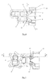
Figure 5 is a left-hand side elevation of the object shown inFigure 3 ; -
Figure 6 is a cross-section along B-B of the object shown inFigure 5 ; -
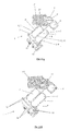
Figure 7 is a perspective view of the second part of the manifold shown inFigures 1 and2 ; -
Figure 8 is a side elevation of the second part shown inFigure 7 ; -
Figure 9 is a cross-section along PC and in perspective of the manifold shown inFigure 1 ; -
Figure 10 is a perspective view of a variation of the manifold shown inFigure 1 , the EGR gas inlet being equipped with an adjustment device, and -
Figures 11A and 11B are cross-sections along A-A (parallel to PC) of the manifold shown inFigure 10 , the adjustment device being in the open and closed position respectively. -
Figures 1 ,2 ,9, 10 and11 show a double-plenum or double-chamber inlet manifold orsplitter 1, made up of a structural unit comprising two distinct coupledplenums 2 and 2' with acommon wall 3, a separate inlet opening 4 and 4' for each of the two plenums and severaldistinct pipes 5 and 5' through each of the said plenums.Superimposed plenums 2 and 2' have substantially flattened general structures and form, with their respectively connected inlet openings and pipes, two independent circulation circuits running from the entrance at theinlet openings 4 and 4' to the outlet at theexternal openings 6 and 6' of the pipes, the said external or outlet openings of the pipes being grouped in pairs, with each pair having anopening 6 and 6' of each of the two types ofpipes 5 and 5'. - According to the invention, this
manifold 1 comprises two one-piece parts 7 and 7' assembled together, in a gas-tight manner, at the continuous assembly areas, afirst part 7 incorporating at least the twoinlet openings 4 and 4' and first portions of thewalls plenums 2 and 2', contiguous to the saidopenings 4 and 4' and the second part 7' incorporating thepipes 5 and 5' and second portions of thewalls plenums 2 and 2', contiguous to the saidpipes 5 and 5' and complementary to the above-mentioned first portions, therespective assembly interfaces consecutive parts 7 and 7' being formed on mutually in-contact complementary edge configurations of the said twoparts 7 and 7'. - Thanks to these different arrangements, the invention enables the above-mentioned main object to be achieved.
- Advantageously, the first portions of wall constitute major portions and the second portions of wall constitute minor portions, each of the
parts 7 and 7' consisting in a one-piece moulded part. - Preferably, the
first part 7 also incorporates at least someexternal portions 12 of the plate or flange and/or someperipheral eyelets 13 for fixing themanifold 1, located around theoutlet openings 6, 6' of thepipes 5, 5', the second part 7' thus forming a cassette type insert clicking into thefirst part 7. - According to an economically and productively practical embodiment, the two
parts 7 and 7' each comprise a thermoplastic material, of the same type or compatible with each other, and they are assembled together by welding, for example by vibration- or infrared-welding. - As shown in
Figures 2 ,7 ,9 and11 , the second part 7' basically incorporateswall portions 8, 8' of theplenums 2 and 2' by extending continually along or inside thepipes 5 and 5' and enclosing thesaid plenums 2 and 2' between thesepipes 5 and 5' and a portion of thewall 3 common to bothplenums 2 and 2'. - In order to create a structure that is simple, easy to manufacture and occupies little space (at least transversely), the
wall 3 and the main parts of thewalls 8 and 8' of the two coupled plenums are advantageously seen in cross-sections along a plane PC perpendicular to the main assembly areas, are substantially arranged in three parallel planes, conferring upon the said plenums general flat structures and internal volumes with substantially rectangular cross-sections, the first portions of thesaid walls first component part 7, having, in section along the said plane PC, a configuration in the shape of a 3 or two Cs superimposed, the middle branch of the 3 or the common branches of the two Cs corresponding to the second component part 7', having, in section along the said plane PC, a complementary configuration of opposite assembly areas and providingsecond wall portions plenums 2 and 2' and continuously connecting thereto thepipes 5 and 5'. - Preferably, the two
component parts 7 and 7' each have threemain assembly interfaces first part 7 and the complementary configuration provided by the second part 7', these three parallellinear assembly interfaces component parts 7 and 7', in order to form continuous combined assembly interfaces at eachplenum 2; 2', corresponding to the edges of the two portions of thecommon wall 3 and theexternal walls 8 and 8' incorporated into the first andsecond parts 7 and 7' respectively. This triple assembly simultaneously creates a seal at the two portions of eachplenum 2 and 2' and ensures that the connection obtained between these two plenums is extremely strong and rigid. - In order to provide a wedged assembly of the second part 7' into the first 7 and ensure that this second part 7' is secured laterally therein, the edges forming the
interfaces 9 of the portions of thewalls 8 and 8' of theplenums 2 and 2' forming an integral part of thefirst component part 7 preferably extend to form a rectangular-section sleeve structure 7" in which is received, by adjusted and preferably sealed click-fitting, the second component part 7' forming an insert, the latter part incorporating, in addition to the walls of thepipes 5 and 5' and the second contiguous portions of thewalls plenums 2 and 2' ending in the interfaces 9' and 10', also portions of filling, connecting and stiffeningstructural walls 16, constituting the body of thefixing plate 12 of thesaid manifold 1. - In order to facilitate assembly (self-centring), achieve an additional mechanical connection with wedging between the two parts and guarantee a precise relative positioning between the latter, the
sleeve structure 7" may have, on both of its opposite sides and substantially parallel to the plane PC,hollow formations 11, notably in the form of outward deformations of the wall of the said sides, cooperating by interconnection of form with complementary formations 11' in the form of portions of opposing side walls of the second part 7', their mutual click-fitting ensuring the alignment of theinterfaces parts 7 and 7', these respectivelycomplementary formations 11 and 11' preferably having contact surfaces that are flat or at right-angles in the form of linear segments, inclined at mutually opposing inclinations, so as to constitute wedge-shaped ortriangular formations 11 and 11' projecting inwards and outwards respectively, the points of which are adjacent to the edges with theassembly interfaces 10 and 10' of the twocomponent parts 7 and 7' at thewall 3 common to bothplenums 2 and 2' (Figures 4, 5 ,7 and 8 ). - According to a particular constructional characteristic of the invention, which also emerges from the accompanying drawings, all of the
outlet openings 6 and 6' of thepipes 5 and 5' connected to the twoplenums 2 and 2' are aligned on the same level, being arranged alternately and being grouped in pairs, and the second part 7' has a general parallelepiped shape, with a substantially rectangular external contour. - Furthermore, as shown in
Figures 2B ,2C ,9 ,11A and 11B , themain assembly interfaces component parts 7 and 7' are in the form of strip surfaces located in the same plane P. -
Compression seals 18, for example a pair of such seals, may be provided on the second part 7' that constitutes an insert, for example at a front side-offset area coming to rest against a complementary internal side-offset of thesleeve structure 7". - According to a possible advantageous development of the invention, referring to
Figure 9 of the accompanying drawings, the inlet opening 4' of the plenum 2' designed to receive the recycled exhaust gases or EGR gas is provided with an insetthermal protection piece 15, preferably a one-piece element 14 made of a heat-resistant material, notably of a heat-hardenable material, thesaid piece 15 comprising onetubular part 15 fitted into the inlet opening 6' concerned and one part in the form of a plate 15' for its external fixing, the said plate 15' also forming a thermal decoupling element. - Such a
piece 15 is notably described in the Applicant's French Patent Application No.0755484 - According to another possible advantageous development of the invention, shown in
Figures 10 and11 of the accompanying drawings, an adjustment device, for example a valve orthrottle 17, connected to an actuator 17', is mounted over the inlet opening 4' of the plenum receiving the EGR gases, or over the end-piece leading to this opening 4', if necessary upstream of the thermal-protection piece 15. - The invention also concerns a motor-vehicle with an internal combustion engine, characterised in that it comprises an
inlet manifold 1 as described above. - Clearly, the invention is not limited to the embodiments described and shown in the accompanying drawings. Modifications are possible, particularly from the point of view of the constitution of the various elements or by making equivalent technical substitutions, without departing from the scope of protection of the invention.
Claims (14)
- Double-plenum or double-chamber inlet manifold or splitter, made up of a structural unit comprising two distinct coupled plenums with a common wall, an inlet opening for each of the two plenums and several pipes through each of the said plenums, the said superimposed plenums having substantially flattened general structures and forming, with their respectively connected inlet openings and pipes, two independent circulation circuits running from the entrance at the inlet openings to the outlet at the external openings of the pipes, the said external or outlet openings of the pipes being grouped in pairs, with each pair having an opening of each of the two types of pipes, manifold (1) characterised in that it comprises two one-piece parts (7 and 7') assembled together, in a gas-tight manner, at the continuous assembly areas, a first part (7) incorporating at least the two inlet openings (4 and 4') and first portions of the walls (3, 8, 8') of the two plenums (2 and 2'), contiguous to the said openings (4 and 4') and the second part (7') incorporating the pipes (5 and 5') and second portions of the walls (3, 8, 8') of the two plenums (2 and 2'), contiguous to the said pipes (5 and 5') and complementary to the above-mentioned first portions, the respective assembly interfaces (9, 10, 11, 9', 10', 11') of the two consecutive parts (7 and 7') being formed on mutually in-contact complementary edge configurations of the said two parts (7 and 7').
- Manifold according to claim 1, characterised in that the first portions of wall constitute major portions and the second portions of wall constitute minor portions, each of the parts (7 and 7') consisting in a one-piece moulded part.
- Manifold according to claim 1 or 2, characterised in that the first part (7) also incorporates at least some external portions (12) of the plate or flange and/or some peripheral eyelets (13) for fixing the manifold (1), located around the outlet openings (6, 6') of the pipes (5, 5'), the second part (7') thus forming a cassette type insert clicking into the first part (7).
- Manifold according to any one of claims 1 to 3, characterised in that the two parts (7 and 7') each comprise a thermoplastic material, of the same type or compatible with each other, and in that they are assembled together by welding, for example by vibration- or infrared-welding.
- Manifold according to any one of claims 1 to 4, characterised in that the second part (7') basically incorporates wall portions (8, 8') of the plenums (2 and 2') by extending continually along or inside the pipes (5 and 5') and enclosing the said plenums (2 and 2') between these pipes (5 and 5') and a portion of the wall (3) common to both plenums (2 and 2').
- Manifold according to claim 5, characterised in that, seen in cross-section along a plane (PC) perpendicular to the main assembly areas, the wall (3) and the main parts of the walls (8 and 8') of the two coupled plenums (2 and 2') are substantially arranged in three parallel planes, conferring upon the said plenums general flat structures and internal volumes with substantially rectangular cross-sections, the first portions of the said walls (3, 8, 8'), incorporated in the first component part (7), having, in section along the plane (PC), a configuration in the shape of a 3 or two superimposed Cs, the middle branch of the 3 shaped configuration or the common branches of the two Cs corresponding to the second component part (7') having, in section along the same plane (PC), a complementary configuration of opposite assembly areas and providing second wall portions (3, 8, 8') enclosing the volumes of the plenums (2 and 2') and continuously connecting thereto the pipes (5 and 5').
- Manifold according to claims 5 and 6, characterised in that the two component parts (7 and 7') each have three main assembly interfaces (9, 10; 9', 10') extending linearly or in a flat strip forming, in cross-section, the three free ends of the 3 shaped configuration provided by the first part (7) and the complementary configuration provided by the second part (7'), these three parallel linear assembly interfaces (9, 10; 9', 10') being connected in pairs together, at the two component parts (7 and 7'), in order to form continuous combined assembly interfaces at each plenum (2; 2'), corresponding to the edges of the two portions of the common wall (3) and the external walls (8 and 8') incorporated into the first and second parts (7 and 7') respectively.
- Manifold according to claim 7, characterised in that the edges forming the interfaces (9) of the portions of the walls (8 and 8') of the plenums (2 and 2') forming an integral part of the first component part (7) extend to form a rectangular-section sleeve structure (7") in which is received, by adjusted and preferably sealed click-fitting, the second component part (7') forming an insert, the latter part incorporating, in addition to the walls of the pipes (5 and 5') and the second contiguous portions of the walls (3, 8, 8') of the plenums (2 and 2') ending in the interfaces (9' and 10'), also portions of filling, connecting and stiffening structural walls (16), constituting the body of the fixing plate (12) of the said manifold (1).
- Manifold according to claim 8, characterised in that the sleeve structure (7") has, on both of its opposite sides and substantially parallel to the plane (PC), hollow formations (11), notably in the form of outward deformations of the wall of the said sides, cooperating by interconnection of form with complementary formations (11') in the form of portions of opposing side walls of the second part (7'), their mutual click-fitting ensuring the alignment of the interfaces (9, 10; 9', 10') mutually opposite the two parts (7 and 7'), these respectively complementary formations (11 and 11') preferably having contact surfaces that are flat or at right-angles in the form of linear segments, inclined at mutually opposing inclinations, so as to constitute wedge-shaped or triangular formations (11 and 11') projecting inwards and outwards respectively, the points of which are adjacent to the edges with the assembly interfaces (10 and 10') of the two component parts (7 and 7') at the wall (3) common to both plenums (2 and 2').
- Manifold according to any one of claims 1 to 9, characterised in that all of the outlet openings (6 and 6') of the pipes (5 and 5') connected to the two plenums (2 and 2') are aligned on the same level, being arranged alternately and being grouped in pairs, and in that the second part (7') has a general parallelepiped shape, with a substantially rectangular external contour.
- Manifold according to any one of claims 1 to 10, characterised in that the main assembly interfaces (9, 10, 9', 10') of the two component parts (7 and 7') are in the form of strip surfaces located in the same plane (P).
- Manifold according to any one of claims 1 to 11, characterised in that the inlet opening (4') of the plenum (2') designed to receive the recycled exhaust gases or EGR gas is provided with an inset thermal protection piece (15), preferably a one-piece element (14) made of a heat-resistant material, notably of a heat-hardenable material, the said piece (15) comprising one tubular part (15) fitted into the inlet opening (6') concerned and one part in the form of a plate (15') for its external fixing, the said plate (15') also forming a thermal decoupling element.
- Manifold according to any one of claims 1 to 12, characterised in that an adjustment device, for example a valve or throttle (17), connected to an actuator (17'), is mounted over the inlet opening (4') of the plenum receiving the EGR gases, or over the end-piece leading to this opening (4'), if necessary upstream of the thermal-protection piece (15).
- Motor-vehicle with an internal combustion engine, characterised in that it comprises an inlet manifold (1) according to any of claims 1 to 13.
Applications Claiming Priority (1)
| Application Number | Priority Date | Filing Date | Title |
|---|---|---|---|
| FR0705112A FR2918715B1 (en) | 2007-07-13 | 2007-07-13 | DOUBLE PLENUM ADMISSION COLLECTOR AND VEHICLE INCORPORATING SUCH A MANIFOLD |
Publications (2)
| Publication Number | Publication Date |
|---|---|
| EP2014906A1 true EP2014906A1 (en) | 2009-01-14 |
| EP2014906B1 EP2014906B1 (en) | 2011-06-08 |
Family
ID=38996684
Family Applications (1)
| Application Number | Title | Priority Date | Filing Date |
|---|---|---|---|
| EP08160296A Not-in-force EP2014906B1 (en) | 2007-07-13 | 2008-07-11 | Double-plenum inlet manifold and vehicle incorporating such a manifold |
Country Status (4)
| Country | Link |
|---|---|
| US (1) | US8434447B2 (en) |
| EP (1) | EP2014906B1 (en) |
| JP (1) | JP2009115076A (en) |
| FR (1) | FR2918715B1 (en) |
Cited By (3)
| Publication number | Priority date | Publication date | Assignee | Title |
|---|---|---|---|---|
| FR2965306A1 (en) * | 2010-09-27 | 2012-03-30 | Valeo Systemes Thermiques | DEVICE FOR MIXING A RECIRCULATED INTAKE GAS FLOW AND A RECIRCULATED EXHAUST GAS FLOW COMPRISING RECIRCULATED EXHAUST GAS FLOW ISOLATION MEANS |
| AT520379A1 (en) * | 2017-12-22 | 2019-03-15 | Avl List Gmbh | Air intake system for a multi-cylinder internal combustion engine |
| WO2022152439A1 (en) * | 2021-01-18 | 2022-07-21 | Mercedes-Benz Group AG | Charge air distributor for an internal combustion engine, in particular of a motor vehicle |
Families Citing this family (1)
| Publication number | Priority date | Publication date | Assignee | Title |
|---|---|---|---|---|
| USD665821S1 (en) * | 2011-11-15 | 2012-08-21 | Rbmark, Inc. | Intake manifold having intake ports with consolidated shape |
Citations (7)
| Publication number | Priority date | Publication date | Assignee | Title |
|---|---|---|---|---|
| FR755484A (en) | 1933-04-20 | 1933-11-25 | cigarette case or other objects | |
| US4970994A (en) * | 1989-02-17 | 1990-11-20 | Nissan Motor Co., Ltd. | Intake manifold for V-type internal combustion engine |
| JPH09100755A (en) * | 1995-10-04 | 1997-04-15 | Inoac Corp | Intake manifold |
| US20020195076A1 (en) * | 2001-06-20 | 2002-12-26 | Toyota Jidosha Kabushiki Kaisha | Variable intake device for internal combustion engines and method for manufacturing the device |
| AT413862B (en) * | 2004-04-23 | 2006-06-15 | Avl List Gmbh | Automotive diesel engine intake manifold incorporates exhaust gas return pipe has two inlet collection voids |
| FR2879249A1 (en) * | 2004-12-09 | 2006-06-16 | Renault Sas | RECYCLED EXHAUST GAS SUPPLY AND STRATIFICATION DEVICE FOR INTERNAL COMBUSTION ENGINE, IN PARTICULAR FOR MOTOR VEHICLE, AND ASSOCIATED METHOD. |
| US20070028883A1 (en) * | 2005-07-11 | 2007-02-08 | Nissan Motor Co., Ltd. | Internal combustion engine intake device |
Family Cites Families (5)
| Publication number | Priority date | Publication date | Assignee | Title |
|---|---|---|---|---|
| FR2133287A5 (en) * | 1971-04-15 | 1972-11-24 | Semt | |
| US5138983A (en) * | 1990-08-07 | 1992-08-18 | Siemens Automotive L. P. | Intake manifold/fuel rail |
| US5713323A (en) * | 1996-10-04 | 1998-02-03 | Ford Motor Company | Integrated air/fuel induction system for an internal combustion engine |
| ITBO20030192A1 (en) * | 2003-04-04 | 2004-10-05 | Marchesini Group Spa | STATION FOR INTERFACING A CONVEYOR LINE |
| FR2875540B1 (en) * | 2004-09-20 | 2007-03-16 | Mark Iv Systemes Moteurs Sa | MULTIFUNCTIONAL MODULE, MOTOR VEHICLE COMPRISING SUCH A MODULE AND METHOD OF MANUFACTURING SUCH A MODULE |
-
2007
- 2007-07-13 FR FR0705112A patent/FR2918715B1/en not_active Expired - Fee Related
-
2008
- 2008-07-11 US US12/171,541 patent/US8434447B2/en not_active Expired - Fee Related
- 2008-07-11 EP EP08160296A patent/EP2014906B1/en not_active Not-in-force
- 2008-07-14 JP JP2008182787A patent/JP2009115076A/en active Pending
Patent Citations (7)
| Publication number | Priority date | Publication date | Assignee | Title |
|---|---|---|---|---|
| FR755484A (en) | 1933-04-20 | 1933-11-25 | cigarette case or other objects | |
| US4970994A (en) * | 1989-02-17 | 1990-11-20 | Nissan Motor Co., Ltd. | Intake manifold for V-type internal combustion engine |
| JPH09100755A (en) * | 1995-10-04 | 1997-04-15 | Inoac Corp | Intake manifold |
| US20020195076A1 (en) * | 2001-06-20 | 2002-12-26 | Toyota Jidosha Kabushiki Kaisha | Variable intake device for internal combustion engines and method for manufacturing the device |
| AT413862B (en) * | 2004-04-23 | 2006-06-15 | Avl List Gmbh | Automotive diesel engine intake manifold incorporates exhaust gas return pipe has two inlet collection voids |
| FR2879249A1 (en) * | 2004-12-09 | 2006-06-16 | Renault Sas | RECYCLED EXHAUST GAS SUPPLY AND STRATIFICATION DEVICE FOR INTERNAL COMBUSTION ENGINE, IN PARTICULAR FOR MOTOR VEHICLE, AND ASSOCIATED METHOD. |
| US20070028883A1 (en) * | 2005-07-11 | 2007-02-08 | Nissan Motor Co., Ltd. | Internal combustion engine intake device |
Cited By (5)
| Publication number | Priority date | Publication date | Assignee | Title |
|---|---|---|---|---|
| FR2965306A1 (en) * | 2010-09-27 | 2012-03-30 | Valeo Systemes Thermiques | DEVICE FOR MIXING A RECIRCULATED INTAKE GAS FLOW AND A RECIRCULATED EXHAUST GAS FLOW COMPRISING RECIRCULATED EXHAUST GAS FLOW ISOLATION MEANS |
| WO2012041563A1 (en) * | 2010-09-27 | 2012-04-05 | Valeo Systemes Thermiques | Device for mixing a stream of inlet gases and of recirculated exhaust gases comprising insulating means for the recirculated exhaust gases |
| US9822735B2 (en) | 2010-09-27 | 2017-11-21 | Valeo Systemes Thermiques | Device for mixing a stream of inlet gases and of recirculated exhaust gases comprising insulating means for the recirculated exhaust gases |
| AT520379A1 (en) * | 2017-12-22 | 2019-03-15 | Avl List Gmbh | Air intake system for a multi-cylinder internal combustion engine |
| WO2022152439A1 (en) * | 2021-01-18 | 2022-07-21 | Mercedes-Benz Group AG | Charge air distributor for an internal combustion engine, in particular of a motor vehicle |
Also Published As
| Publication number | Publication date |
|---|---|
| US8434447B2 (en) | 2013-05-07 |
| JP2009115076A (en) | 2009-05-28 |
| FR2918715B1 (en) | 2009-08-28 |
| US20090071430A1 (en) | 2009-03-19 |
| EP2014906B1 (en) | 2011-06-08 |
| FR2918715A1 (en) | 2009-01-16 |
Similar Documents
| Publication | Publication Date | Title |
|---|---|---|
| US9359980B2 (en) | Intake system | |
| US20120285423A1 (en) | Intake manifold having an integrated charge air cooler | |
| KR101639509B1 (en) | Heat exchanger having a reinforced collector | |
| EP2014906B1 (en) | Double-plenum inlet manifold and vehicle incorporating such a manifold | |
| CN102192040A (en) | Cooling water passage structure in cylinder head of internal combustion engine | |
| US10422307B2 (en) | Air intake manifold | |
| US7198040B2 (en) | Intake device of internal combustion engine | |
| CA2830698A1 (en) | Heat exchanger with resiliently mounted bracket | |
| EP1522714A2 (en) | Intake device for internal combustion engine | |
| US10174726B2 (en) | Intake manifold | |
| EP1422414A1 (en) | Intake manifold in two parts | |
| US20080141971A1 (en) | Cylinder head and exhaust system of a multi-cylinder engine | |
| US8800509B2 (en) | Scavenging passage structure for two-stroke engine | |
| US20150176922A1 (en) | Heat Exchanger Having A Reinforced Collector | |
| JP6350636B2 (en) | Intake device for multi-cylinder engine with intercooler | |
| US20150021004A1 (en) | EGR Cooler | |
| JP6399074B2 (en) | Engine intake system with intercooler | |
| CN101457707B (en) | Integrally formed engine exhaust manifold and cylinder head | |
| JP2005069060A (en) | Engine exhaust gas recirculation system | |
| JP2008208770A (en) | Intake manifold structure | |
| KR20120026757A (en) | Intake manifold having the heat protector | |
| JP2002364470A (en) | Intake manifold | |
| JP2018080658A (en) | Intake system for multi-cylinder engine with egr device and method for manufacturing the same | |
| KR102692102B1 (en) | Water-cooled intercooler | |
| JP6394680B2 (en) | Intake device for multi-cylinder engine with intercooler |
Legal Events
| Date | Code | Title | Description |
|---|---|---|---|
| PUAI | Public reference made under article 153(3) epc to a published international application that has entered the european phase |
Free format text: ORIGINAL CODE: 0009012 |
|
| AK | Designated contracting states |
Kind code of ref document: A1 Designated state(s): AT BE BG CH CY CZ DE DK EE ES FI FR GB GR HR HU IE IS IT LI LT LU LV MC MT NL NO PL PT RO SE SI SK TR |
|
| AX | Request for extension of the european patent |
Extension state: AL BA MK RS |
|
| RIN1 | Information on inventor provided before grant (corrected) |
Inventor name: MENIN, DENIS Inventor name: GERMAIN, LAURENT |
|
| 17P | Request for examination filed |
Effective date: 20090609 |
|
| 17Q | First examination report despatched |
Effective date: 20090715 |
|
| AKX | Designation fees paid |
Designated state(s): DE FR |
|
| GRAP | Despatch of communication of intention to grant a patent |
Free format text: ORIGINAL CODE: EPIDOSNIGR1 |
|
| GRAS | Grant fee paid |
Free format text: ORIGINAL CODE: EPIDOSNIGR3 |
|
| RAP1 | Party data changed (applicant data changed or rights of an application transferred) |
Owner name: MARK IV SYSTEMES MOTEURS (SAS) |
|
| GRAA | (expected) grant |
Free format text: ORIGINAL CODE: 0009210 |
|
| AK | Designated contracting states |
Kind code of ref document: B1 Designated state(s): DE FR |
|
| REG | Reference to a national code |
Ref country code: DE Ref legal event code: R096 Ref document number: 602008007397 Country of ref document: DE Effective date: 20110721 |
|
| PLBE | No opposition filed within time limit |
Free format text: ORIGINAL CODE: 0009261 |
|
| STAA | Information on the status of an ep patent application or granted ep patent |
Free format text: STATUS: NO OPPOSITION FILED WITHIN TIME LIMIT |
|
| 26N | No opposition filed |
Effective date: 20120309 |
|
| REG | Reference to a national code |
Ref country code: DE Ref legal event code: R097 Ref document number: 602008007397 Country of ref document: DE Effective date: 20120309 |
|
| PGFP | Annual fee paid to national office [announced via postgrant information from national office to epo] |
Ref country code: DE Payment date: 20120713 Year of fee payment: 5 |
|
| REG | Reference to a national code |
Ref country code: DE Ref legal event code: R119 Ref document number: 602008007397 Country of ref document: DE Effective date: 20140201 |
|
| PG25 | Lapsed in a contracting state [announced via postgrant information from national office to epo] |
Ref country code: DE Free format text: LAPSE BECAUSE OF NON-PAYMENT OF DUE FEES Effective date: 20140201 |
|
| REG | Reference to a national code |
Ref country code: FR Ref legal event code: PLFP Year of fee payment: 9 |
|
| REG | Reference to a national code |
Ref country code: FR Ref legal event code: PLFP Year of fee payment: 10 |
|
| REG | Reference to a national code |
Ref country code: FR Ref legal event code: PLFP Year of fee payment: 11 |
|
| PGFP | Annual fee paid to national office [announced via postgrant information from national office to epo] |
Ref country code: FR Payment date: 20230621 Year of fee payment: 16 |
|
| PG25 | Lapsed in a contracting state [announced via postgrant information from national office to epo] |
Ref country code: FR Free format text: LAPSE BECAUSE OF NON-PAYMENT OF DUE FEES Effective date: 20240731 |