EP2014529B1 - An engine start control device and method for a hybrid vehicle - Google Patents
An engine start control device and method for a hybrid vehicle Download PDFInfo
- Publication number
- EP2014529B1 EP2014529B1 EP08165041A EP08165041A EP2014529B1 EP 2014529 B1 EP2014529 B1 EP 2014529B1 EP 08165041 A EP08165041 A EP 08165041A EP 08165041 A EP08165041 A EP 08165041A EP 2014529 B1 EP2014529 B1 EP 2014529B1
- Authority
- EP
- European Patent Office
- Prior art keywords
- engine
- demand
- acceleration demand
- pressure
- control device
- Prior art date
- Legal status (The legal status is an assumption and is not a legal conclusion. Google has not performed a legal analysis and makes no representation as to the accuracy of the status listed.)
- Active
Links
- 238000000034 method Methods 0.000 title claims description 12
- 230000001133 acceleration Effects 0.000 claims description 37
- 239000000446 fuel Substances 0.000 claims description 26
- 238000010248 power generation Methods 0.000 claims description 26
- 238000002347 injection Methods 0.000 claims description 22
- 239000007924 injection Substances 0.000 claims description 22
- 230000006698 induction Effects 0.000 claims description 20
- 230000007423 decrease Effects 0.000 claims description 10
- 230000001172 regenerating effect Effects 0.000 description 25
- 230000007246 mechanism Effects 0.000 description 12
- 230000035939 shock Effects 0.000 description 9
- 230000009467 reduction Effects 0.000 description 7
- 238000010586 diagram Methods 0.000 description 6
- 230000004044 response Effects 0.000 description 4
- 230000005540 biological transmission Effects 0.000 description 2
- 239000003990 capacitor Substances 0.000 description 2
- 230000001360 synchronised effect Effects 0.000 description 2
- 101150028668 APO1 gene Proteins 0.000 description 1
- HBBGRARXTFLTSG-UHFFFAOYSA-N Lithium ion Chemical compound [Li+] HBBGRARXTFLTSG-UHFFFAOYSA-N 0.000 description 1
- PXHVJJICTQNCMI-UHFFFAOYSA-N Nickel Chemical compound [Ni] PXHVJJICTQNCMI-UHFFFAOYSA-N 0.000 description 1
- 239000002253 acid Substances 0.000 description 1
- 230000009471 action Effects 0.000 description 1
- 230000002411 adverse Effects 0.000 description 1
- 230000008859 change Effects 0.000 description 1
- 238000002485 combustion reaction Methods 0.000 description 1
- 230000003247 decreasing effect Effects 0.000 description 1
- 238000001514 detection method Methods 0.000 description 1
- 230000006866 deterioration Effects 0.000 description 1
- 229910001416 lithium ion Inorganic materials 0.000 description 1
- 239000000203 mixture Substances 0.000 description 1
- 229910000652 nickel hydride Inorganic materials 0.000 description 1
Images


Classifications
-
- B—PERFORMING OPERATIONS; TRANSPORTING
- B60—VEHICLES IN GENERAL
- B60K—ARRANGEMENT OR MOUNTING OF PROPULSION UNITS OR OF TRANSMISSIONS IN VEHICLES; ARRANGEMENT OR MOUNTING OF PLURAL DIVERSE PRIME-MOVERS IN VEHICLES; AUXILIARY DRIVES FOR VEHICLES; INSTRUMENTATION OR DASHBOARDS FOR VEHICLES; ARRANGEMENTS IN CONNECTION WITH COOLING, AIR INTAKE, GAS EXHAUST OR FUEL SUPPLY OF PROPULSION UNITS IN VEHICLES
- B60K6/00—Arrangement or mounting of plural diverse prime-movers for mutual or common propulsion, e.g. hybrid propulsion systems comprising electric motors and internal combustion engines ; Control systems therefor, i.e. systems controlling two or more prime movers, or controlling one of these prime movers and any of the transmission, drive or drive units Informative references: mechanical gearings with secondary electric drive F16H3/72; arrangements for handling mechanical energy structurally associated with the dynamo-electric machine H02K7/00; machines comprising structurally interrelated motor and generator parts H02K51/00; dynamo-electric machines not otherwise provided for in H02K see H02K99/00
- B60K6/20—Arrangement or mounting of plural diverse prime-movers for mutual or common propulsion, e.g. hybrid propulsion systems comprising electric motors and internal combustion engines ; Control systems therefor, i.e. systems controlling two or more prime movers, or controlling one of these prime movers and any of the transmission, drive or drive units Informative references: mechanical gearings with secondary electric drive F16H3/72; arrangements for handling mechanical energy structurally associated with the dynamo-electric machine H02K7/00; machines comprising structurally interrelated motor and generator parts H02K51/00; dynamo-electric machines not otherwise provided for in H02K see H02K99/00 the prime-movers consisting of electric motors and internal combustion engines, e.g. HEVs
- B60K6/22—Arrangement or mounting of plural diverse prime-movers for mutual or common propulsion, e.g. hybrid propulsion systems comprising electric motors and internal combustion engines ; Control systems therefor, i.e. systems controlling two or more prime movers, or controlling one of these prime movers and any of the transmission, drive or drive units Informative references: mechanical gearings with secondary electric drive F16H3/72; arrangements for handling mechanical energy structurally associated with the dynamo-electric machine H02K7/00; machines comprising structurally interrelated motor and generator parts H02K51/00; dynamo-electric machines not otherwise provided for in H02K see H02K99/00 the prime-movers consisting of electric motors and internal combustion engines, e.g. HEVs characterised by apparatus, components or means specially adapted for HEVs
- B60K6/36—Arrangement or mounting of plural diverse prime-movers for mutual or common propulsion, e.g. hybrid propulsion systems comprising electric motors and internal combustion engines ; Control systems therefor, i.e. systems controlling two or more prime movers, or controlling one of these prime movers and any of the transmission, drive or drive units Informative references: mechanical gearings with secondary electric drive F16H3/72; arrangements for handling mechanical energy structurally associated with the dynamo-electric machine H02K7/00; machines comprising structurally interrelated motor and generator parts H02K51/00; dynamo-electric machines not otherwise provided for in H02K see H02K99/00 the prime-movers consisting of electric motors and internal combustion engines, e.g. HEVs characterised by apparatus, components or means specially adapted for HEVs characterised by the transmission gearings
- B60K6/365—Arrangement or mounting of plural diverse prime-movers for mutual or common propulsion, e.g. hybrid propulsion systems comprising electric motors and internal combustion engines ; Control systems therefor, i.e. systems controlling two or more prime movers, or controlling one of these prime movers and any of the transmission, drive or drive units Informative references: mechanical gearings with secondary electric drive F16H3/72; arrangements for handling mechanical energy structurally associated with the dynamo-electric machine H02K7/00; machines comprising structurally interrelated motor and generator parts H02K51/00; dynamo-electric machines not otherwise provided for in H02K see H02K99/00 the prime-movers consisting of electric motors and internal combustion engines, e.g. HEVs characterised by apparatus, components or means specially adapted for HEVs characterised by the transmission gearings with the gears having orbital motion
-
- B—PERFORMING OPERATIONS; TRANSPORTING
- B60—VEHICLES IN GENERAL
- B60K—ARRANGEMENT OR MOUNTING OF PROPULSION UNITS OR OF TRANSMISSIONS IN VEHICLES; ARRANGEMENT OR MOUNTING OF PLURAL DIVERSE PRIME-MOVERS IN VEHICLES; AUXILIARY DRIVES FOR VEHICLES; INSTRUMENTATION OR DASHBOARDS FOR VEHICLES; ARRANGEMENTS IN CONNECTION WITH COOLING, AIR INTAKE, GAS EXHAUST OR FUEL SUPPLY OF PROPULSION UNITS IN VEHICLES
- B60K6/00—Arrangement or mounting of plural diverse prime-movers for mutual or common propulsion, e.g. hybrid propulsion systems comprising electric motors and internal combustion engines ; Control systems therefor, i.e. systems controlling two or more prime movers, or controlling one of these prime movers and any of the transmission, drive or drive units Informative references: mechanical gearings with secondary electric drive F16H3/72; arrangements for handling mechanical energy structurally associated with the dynamo-electric machine H02K7/00; machines comprising structurally interrelated motor and generator parts H02K51/00; dynamo-electric machines not otherwise provided for in H02K see H02K99/00
- B60K6/20—Arrangement or mounting of plural diverse prime-movers for mutual or common propulsion, e.g. hybrid propulsion systems comprising electric motors and internal combustion engines ; Control systems therefor, i.e. systems controlling two or more prime movers, or controlling one of these prime movers and any of the transmission, drive or drive units Informative references: mechanical gearings with secondary electric drive F16H3/72; arrangements for handling mechanical energy structurally associated with the dynamo-electric machine H02K7/00; machines comprising structurally interrelated motor and generator parts H02K51/00; dynamo-electric machines not otherwise provided for in H02K see H02K99/00 the prime-movers consisting of electric motors and internal combustion engines, e.g. HEVs
- B60K6/42—Arrangement or mounting of plural diverse prime-movers for mutual or common propulsion, e.g. hybrid propulsion systems comprising electric motors and internal combustion engines ; Control systems therefor, i.e. systems controlling two or more prime movers, or controlling one of these prime movers and any of the transmission, drive or drive units Informative references: mechanical gearings with secondary electric drive F16H3/72; arrangements for handling mechanical energy structurally associated with the dynamo-electric machine H02K7/00; machines comprising structurally interrelated motor and generator parts H02K51/00; dynamo-electric machines not otherwise provided for in H02K see H02K99/00 the prime-movers consisting of electric motors and internal combustion engines, e.g. HEVs characterised by the architecture of the hybrid electric vehicle
- B60K6/44—Series-parallel type
- B60K6/445—Differential gearing distribution type
-
- B—PERFORMING OPERATIONS; TRANSPORTING
- B60—VEHICLES IN GENERAL
- B60L—PROPULSION OF ELECTRICALLY-PROPELLED VEHICLES; SUPPLYING ELECTRIC POWER FOR AUXILIARY EQUIPMENT OF ELECTRICALLY-PROPELLED VEHICLES; ELECTRODYNAMIC BRAKE SYSTEMS FOR VEHICLES IN GENERAL; MAGNETIC SUSPENSION OR LEVITATION FOR VEHICLES; MONITORING OPERATING VARIABLES OF ELECTRICALLY-PROPELLED VEHICLES; ELECTRIC SAFETY DEVICES FOR ELECTRICALLY-PROPELLED VEHICLES
- B60L15/00—Methods, circuits, or devices for controlling the traction-motor speed of electrically-propelled vehicles
- B60L15/20—Methods, circuits, or devices for controlling the traction-motor speed of electrically-propelled vehicles for control of the vehicle or its driving motor to achieve a desired performance, e.g. speed, torque, programmed variation of speed
-
- B—PERFORMING OPERATIONS; TRANSPORTING
- B60—VEHICLES IN GENERAL
- B60L—PROPULSION OF ELECTRICALLY-PROPELLED VEHICLES; SUPPLYING ELECTRIC POWER FOR AUXILIARY EQUIPMENT OF ELECTRICALLY-PROPELLED VEHICLES; ELECTRODYNAMIC BRAKE SYSTEMS FOR VEHICLES IN GENERAL; MAGNETIC SUSPENSION OR LEVITATION FOR VEHICLES; MONITORING OPERATING VARIABLES OF ELECTRICALLY-PROPELLED VEHICLES; ELECTRIC SAFETY DEVICES FOR ELECTRICALLY-PROPELLED VEHICLES
- B60L50/00—Electric propulsion with power supplied within the vehicle
- B60L50/10—Electric propulsion with power supplied within the vehicle using propulsion power supplied by engine-driven generators, e.g. generators driven by combustion engines
- B60L50/16—Electric propulsion with power supplied within the vehicle using propulsion power supplied by engine-driven generators, e.g. generators driven by combustion engines with provision for separate direct mechanical propulsion
-
- B—PERFORMING OPERATIONS; TRANSPORTING
- B60—VEHICLES IN GENERAL
- B60W—CONJOINT CONTROL OF VEHICLE SUB-UNITS OF DIFFERENT TYPE OR DIFFERENT FUNCTION; CONTROL SYSTEMS SPECIALLY ADAPTED FOR HYBRID VEHICLES; ROAD VEHICLE DRIVE CONTROL SYSTEMS FOR PURPOSES NOT RELATED TO THE CONTROL OF A PARTICULAR SUB-UNIT
- B60W10/00—Conjoint control of vehicle sub-units of different type or different function
- B60W10/04—Conjoint control of vehicle sub-units of different type or different function including control of propulsion units
- B60W10/06—Conjoint control of vehicle sub-units of different type or different function including control of propulsion units including control of combustion engines
-
- B—PERFORMING OPERATIONS; TRANSPORTING
- B60—VEHICLES IN GENERAL
- B60K—ARRANGEMENT OR MOUNTING OF PROPULSION UNITS OR OF TRANSMISSIONS IN VEHICLES; ARRANGEMENT OR MOUNTING OF PLURAL DIVERSE PRIME-MOVERS IN VEHICLES; AUXILIARY DRIVES FOR VEHICLES; INSTRUMENTATION OR DASHBOARDS FOR VEHICLES; ARRANGEMENTS IN CONNECTION WITH COOLING, AIR INTAKE, GAS EXHAUST OR FUEL SUPPLY OF PROPULSION UNITS IN VEHICLES
- B60K1/00—Arrangement or mounting of electrical propulsion units
- B60K1/02—Arrangement or mounting of electrical propulsion units comprising more than one electric motor
-
- B—PERFORMING OPERATIONS; TRANSPORTING
- B60—VEHICLES IN GENERAL
- B60L—PROPULSION OF ELECTRICALLY-PROPELLED VEHICLES; SUPPLYING ELECTRIC POWER FOR AUXILIARY EQUIPMENT OF ELECTRICALLY-PROPELLED VEHICLES; ELECTRODYNAMIC BRAKE SYSTEMS FOR VEHICLES IN GENERAL; MAGNETIC SUSPENSION OR LEVITATION FOR VEHICLES; MONITORING OPERATING VARIABLES OF ELECTRICALLY-PROPELLED VEHICLES; ELECTRIC SAFETY DEVICES FOR ELECTRICALLY-PROPELLED VEHICLES
- B60L2240/00—Control parameters of input or output; Target parameters
- B60L2240/40—Drive Train control parameters
- B60L2240/42—Drive Train control parameters related to electric machines
- B60L2240/423—Torque
-
- B—PERFORMING OPERATIONS; TRANSPORTING
- B60—VEHICLES IN GENERAL
- B60L—PROPULSION OF ELECTRICALLY-PROPELLED VEHICLES; SUPPLYING ELECTRIC POWER FOR AUXILIARY EQUIPMENT OF ELECTRICALLY-PROPELLED VEHICLES; ELECTRODYNAMIC BRAKE SYSTEMS FOR VEHICLES IN GENERAL; MAGNETIC SUSPENSION OR LEVITATION FOR VEHICLES; MONITORING OPERATING VARIABLES OF ELECTRICALLY-PROPELLED VEHICLES; ELECTRIC SAFETY DEVICES FOR ELECTRICALLY-PROPELLED VEHICLES
- B60L2240/00—Control parameters of input or output; Target parameters
- B60L2240/40—Drive Train control parameters
- B60L2240/44—Drive Train control parameters related to combustion engines
- B60L2240/443—Torque
-
- B—PERFORMING OPERATIONS; TRANSPORTING
- B60—VEHICLES IN GENERAL
- B60L—PROPULSION OF ELECTRICALLY-PROPELLED VEHICLES; SUPPLYING ELECTRIC POWER FOR AUXILIARY EQUIPMENT OF ELECTRICALLY-PROPELLED VEHICLES; ELECTRODYNAMIC BRAKE SYSTEMS FOR VEHICLES IN GENERAL; MAGNETIC SUSPENSION OR LEVITATION FOR VEHICLES; MONITORING OPERATING VARIABLES OF ELECTRICALLY-PROPELLED VEHICLES; ELECTRIC SAFETY DEVICES FOR ELECTRICALLY-PROPELLED VEHICLES
- B60L2240/00—Control parameters of input or output; Target parameters
- B60L2240/80—Time limits
-
- B—PERFORMING OPERATIONS; TRANSPORTING
- B60—VEHICLES IN GENERAL
- B60L—PROPULSION OF ELECTRICALLY-PROPELLED VEHICLES; SUPPLYING ELECTRIC POWER FOR AUXILIARY EQUIPMENT OF ELECTRICALLY-PROPELLED VEHICLES; ELECTRODYNAMIC BRAKE SYSTEMS FOR VEHICLES IN GENERAL; MAGNETIC SUSPENSION OR LEVITATION FOR VEHICLES; MONITORING OPERATING VARIABLES OF ELECTRICALLY-PROPELLED VEHICLES; ELECTRIC SAFETY DEVICES FOR ELECTRICALLY-PROPELLED VEHICLES
- B60L2250/00—Driver interactions
- B60L2250/26—Driver interactions by pedal actuation
-
- B—PERFORMING OPERATIONS; TRANSPORTING
- B60—VEHICLES IN GENERAL
- B60L—PROPULSION OF ELECTRICALLY-PROPELLED VEHICLES; SUPPLYING ELECTRIC POWER FOR AUXILIARY EQUIPMENT OF ELECTRICALLY-PROPELLED VEHICLES; ELECTRODYNAMIC BRAKE SYSTEMS FOR VEHICLES IN GENERAL; MAGNETIC SUSPENSION OR LEVITATION FOR VEHICLES; MONITORING OPERATING VARIABLES OF ELECTRICALLY-PROPELLED VEHICLES; ELECTRIC SAFETY DEVICES FOR ELECTRICALLY-PROPELLED VEHICLES
- B60L2260/00—Operating Modes
- B60L2260/20—Drive modes; Transition between modes
- B60L2260/26—Transition between different drive modes
-
- B—PERFORMING OPERATIONS; TRANSPORTING
- B60—VEHICLES IN GENERAL
- B60L—PROPULSION OF ELECTRICALLY-PROPELLED VEHICLES; SUPPLYING ELECTRIC POWER FOR AUXILIARY EQUIPMENT OF ELECTRICALLY-PROPELLED VEHICLES; ELECTRODYNAMIC BRAKE SYSTEMS FOR VEHICLES IN GENERAL; MAGNETIC SUSPENSION OR LEVITATION FOR VEHICLES; MONITORING OPERATING VARIABLES OF ELECTRICALLY-PROPELLED VEHICLES; ELECTRIC SAFETY DEVICES FOR ELECTRICALLY-PROPELLED VEHICLES
- B60L2270/00—Problem solutions or means not otherwise provided for
- B60L2270/10—Emission reduction
- B60L2270/14—Emission reduction of noise
- B60L2270/145—Structure borne vibrations
-
- B—PERFORMING OPERATIONS; TRANSPORTING
- B60—VEHICLES IN GENERAL
- B60W—CONJOINT CONTROL OF VEHICLE SUB-UNITS OF DIFFERENT TYPE OR DIFFERENT FUNCTION; CONTROL SYSTEMS SPECIALLY ADAPTED FOR HYBRID VEHICLES; ROAD VEHICLE DRIVE CONTROL SYSTEMS FOR PURPOSES NOT RELATED TO THE CONTROL OF A PARTICULAR SUB-UNIT
- B60W2510/00—Input parameters relating to a particular sub-units
- B60W2510/06—Combustion engines, Gas turbines
- B60W2510/0671—Engine manifold pressure
-
- B—PERFORMING OPERATIONS; TRANSPORTING
- B60—VEHICLES IN GENERAL
- B60W—CONJOINT CONTROL OF VEHICLE SUB-UNITS OF DIFFERENT TYPE OR DIFFERENT FUNCTION; CONTROL SYSTEMS SPECIALLY ADAPTED FOR HYBRID VEHICLES; ROAD VEHICLE DRIVE CONTROL SYSTEMS FOR PURPOSES NOT RELATED TO THE CONTROL OF A PARTICULAR SUB-UNIT
- B60W2540/00—Input parameters relating to occupants
- B60W2540/10—Accelerator pedal position
-
- B—PERFORMING OPERATIONS; TRANSPORTING
- B60—VEHICLES IN GENERAL
- B60W—CONJOINT CONTROL OF VEHICLE SUB-UNITS OF DIFFERENT TYPE OR DIFFERENT FUNCTION; CONTROL SYSTEMS SPECIALLY ADAPTED FOR HYBRID VEHICLES; ROAD VEHICLE DRIVE CONTROL SYSTEMS FOR PURPOSES NOT RELATED TO THE CONTROL OF A PARTICULAR SUB-UNIT
- B60W2710/00—Output or target parameters relating to a particular sub-units
- B60W2710/06—Combustion engines, Gas turbines
- B60W2710/0605—Throttle position
-
- B—PERFORMING OPERATIONS; TRANSPORTING
- B60—VEHICLES IN GENERAL
- B60W—CONJOINT CONTROL OF VEHICLE SUB-UNITS OF DIFFERENT TYPE OR DIFFERENT FUNCTION; CONTROL SYSTEMS SPECIALLY ADAPTED FOR HYBRID VEHICLES; ROAD VEHICLE DRIVE CONTROL SYSTEMS FOR PURPOSES NOT RELATED TO THE CONTROL OF A PARTICULAR SUB-UNIT
- B60W2710/00—Output or target parameters relating to a particular sub-units
- B60W2710/06—Combustion engines, Gas turbines
- B60W2710/0616—Position of fuel or air injector
-
- Y—GENERAL TAGGING OF NEW TECHNOLOGICAL DEVELOPMENTS; GENERAL TAGGING OF CROSS-SECTIONAL TECHNOLOGIES SPANNING OVER SEVERAL SECTIONS OF THE IPC; TECHNICAL SUBJECTS COVERED BY FORMER USPC CROSS-REFERENCE ART COLLECTIONS [XRACs] AND DIGESTS
- Y02—TECHNOLOGIES OR APPLICATIONS FOR MITIGATION OR ADAPTATION AGAINST CLIMATE CHANGE
- Y02T—CLIMATE CHANGE MITIGATION TECHNOLOGIES RELATED TO TRANSPORTATION
- Y02T10/00—Road transport of goods or passengers
- Y02T10/10—Internal combustion engine [ICE] based vehicles
- Y02T10/40—Engine management systems
-
- Y—GENERAL TAGGING OF NEW TECHNOLOGICAL DEVELOPMENTS; GENERAL TAGGING OF CROSS-SECTIONAL TECHNOLOGIES SPANNING OVER SEVERAL SECTIONS OF THE IPC; TECHNICAL SUBJECTS COVERED BY FORMER USPC CROSS-REFERENCE ART COLLECTIONS [XRACs] AND DIGESTS
- Y02—TECHNOLOGIES OR APPLICATIONS FOR MITIGATION OR ADAPTATION AGAINST CLIMATE CHANGE
- Y02T—CLIMATE CHANGE MITIGATION TECHNOLOGIES RELATED TO TRANSPORTATION
- Y02T10/00—Road transport of goods or passengers
- Y02T10/60—Other road transportation technologies with climate change mitigation effect
- Y02T10/62—Hybrid vehicles
-
- Y—GENERAL TAGGING OF NEW TECHNOLOGICAL DEVELOPMENTS; GENERAL TAGGING OF CROSS-SECTIONAL TECHNOLOGIES SPANNING OVER SEVERAL SECTIONS OF THE IPC; TECHNICAL SUBJECTS COVERED BY FORMER USPC CROSS-REFERENCE ART COLLECTIONS [XRACs] AND DIGESTS
- Y02—TECHNOLOGIES OR APPLICATIONS FOR MITIGATION OR ADAPTATION AGAINST CLIMATE CHANGE
- Y02T—CLIMATE CHANGE MITIGATION TECHNOLOGIES RELATED TO TRANSPORTATION
- Y02T10/00—Road transport of goods or passengers
- Y02T10/60—Other road transportation technologies with climate change mitigation effect
- Y02T10/64—Electric machine technologies in electromobility
-
- Y—GENERAL TAGGING OF NEW TECHNOLOGICAL DEVELOPMENTS; GENERAL TAGGING OF CROSS-SECTIONAL TECHNOLOGIES SPANNING OVER SEVERAL SECTIONS OF THE IPC; TECHNICAL SUBJECTS COVERED BY FORMER USPC CROSS-REFERENCE ART COLLECTIONS [XRACs] AND DIGESTS
- Y02—TECHNOLOGIES OR APPLICATIONS FOR MITIGATION OR ADAPTATION AGAINST CLIMATE CHANGE
- Y02T—CLIMATE CHANGE MITIGATION TECHNOLOGIES RELATED TO TRANSPORTATION
- Y02T10/00—Road transport of goods or passengers
- Y02T10/60—Other road transportation technologies with climate change mitigation effect
- Y02T10/70—Energy storage systems for electromobility, e.g. batteries
-
- Y—GENERAL TAGGING OF NEW TECHNOLOGICAL DEVELOPMENTS; GENERAL TAGGING OF CROSS-SECTIONAL TECHNOLOGIES SPANNING OVER SEVERAL SECTIONS OF THE IPC; TECHNICAL SUBJECTS COVERED BY FORMER USPC CROSS-REFERENCE ART COLLECTIONS [XRACs] AND DIGESTS
- Y02—TECHNOLOGIES OR APPLICATIONS FOR MITIGATION OR ADAPTATION AGAINST CLIMATE CHANGE
- Y02T—CLIMATE CHANGE MITIGATION TECHNOLOGIES RELATED TO TRANSPORTATION
- Y02T10/00—Road transport of goods or passengers
- Y02T10/60—Other road transportation technologies with climate change mitigation effect
- Y02T10/7072—Electromobility specific charging systems or methods for batteries, ultracapacitors, supercapacitors or double-layer capacitors
-
- Y—GENERAL TAGGING OF NEW TECHNOLOGICAL DEVELOPMENTS; GENERAL TAGGING OF CROSS-SECTIONAL TECHNOLOGIES SPANNING OVER SEVERAL SECTIONS OF THE IPC; TECHNICAL SUBJECTS COVERED BY FORMER USPC CROSS-REFERENCE ART COLLECTIONS [XRACs] AND DIGESTS
- Y02—TECHNOLOGIES OR APPLICATIONS FOR MITIGATION OR ADAPTATION AGAINST CLIMATE CHANGE
- Y02T—CLIMATE CHANGE MITIGATION TECHNOLOGIES RELATED TO TRANSPORTATION
- Y02T10/00—Road transport of goods or passengers
- Y02T10/60—Other road transportation technologies with climate change mitigation effect
- Y02T10/72—Electric energy management in electromobility
-
- Y—GENERAL TAGGING OF NEW TECHNOLOGICAL DEVELOPMENTS; GENERAL TAGGING OF CROSS-SECTIONAL TECHNOLOGIES SPANNING OVER SEVERAL SECTIONS OF THE IPC; TECHNICAL SUBJECTS COVERED BY FORMER USPC CROSS-REFERENCE ART COLLECTIONS [XRACs] AND DIGESTS
- Y10—TECHNICAL SUBJECTS COVERED BY FORMER USPC
- Y10T—TECHNICAL SUBJECTS COVERED BY FORMER US CLASSIFICATION
- Y10T74/00—Machine element or mechanism
- Y10T74/20—Control lever and linkage systems
- Y10T74/20528—Foot operated
- Y10T74/2054—Signal
Description
- The present invention relates to an engine start control device and method for a hybrid vehicle which is equipped with a motor and an engine.
- A hybrid vehicle having both a motor and an engine is powered only by a motor when the vehicle is under a small load. When the load increases, the hybrid vehicle starts the engine to provide additional driving force. When the hybrid vehicle shifts from running only with a motor to using the engine as well, it is necessary to rapidly start the engine. If it takes a long time to start the engine, the driving force cannot be smoothly controlled, which deteriorates vehicle performance.
- Therefore, the time required to start the engine may be reduced by controlling the action timing of the induction system at the time the engine starts. However, when the engine start time is shortened as described above, the engine torque is applied immediately after the complete combustion of the engine start, which results in an engine start shock. The driver tends to feel the engine start shock, particularly when the vehicle is accelerated slowly.
-
US2002/0063002 discloses an apparatus and method relevant to the present invention, in line with the features of the preamble ofclaim 1. - In general, the present invention is directed to an engine start control device and method for a hybrid vehicle which may prevent the shock that the driver feels during slow acceleration and also provides good throttle response when rapid acceleration is required.
- In one aspect, the present invention is directed to an engine start control device for a hybrid vehicle as claimed in
claim 1 appended hereto. - In another aspect, the present invention is directed to a method as claimed in
claim 11 appended hereto. - The details of one or more embodiments of the invention are set forth in the accompanying drawings and the description below. Other features, objects, and advantages of the invention will be apparent from the description and drawings, and from the claims.
-
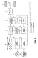
FIG. 1 is a schematic block diagram illustrating the structure of an embodiment of the engine start control device for a hybrid vehicle; -
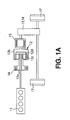
FIG. 1A is a schematic diagram illustrating the driveline of a hybrid vehicle; -
FIG. 1B is a plot showing the relationship between the components of a planetary gear mechanism; -
FIG. 1C is a plot showing the relationship between the components of a planetary gear mechanism; -
FIG. 2 is a main flowchart indicating the operation of the engine start control device for a hybrid vehicle; -
FIG. 3 is a flowchart of the target setting routine; -
FIG. 4 is a graph indicating target gate opening TV01 of the throttle valve versus the amount of pressure on the accelerator pedal; -
FIG. 5 is a graph indicating target delay time Ta for the fuel injection versus the amount of pressure on the accelerator pedal; -
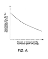
FIG. 6 is a graph indicating target delay time Tb for the fuel injection versus the rate of the pressure on the accelerator pedal; -
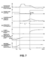
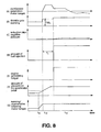
FIG. 7 is a time chart of the case where the amount of pressure on the accelerator pedal is small (AP0 ≤ AP01); and -
FIG. 8 is a time chart of the case where the amount of pressure on the accelerator pedal is large (AP0 > AP01). - The embodiments of the present invention will be described in detail below by referring to the drawings, but the present invention is not limited to this embodiment.
-
FIG. 1 is a block diagram illustrating an embodiment of the engine start control device for a hybrid vehicle. InFIG. 1 , the thick solid line indicates the route through which mechanical energy is transmitted, the dashed line indicates the electric power line, and the thin solid line indicates the control line. - Referring to
FIG. 1 , ahybrid vehicle 10 includes anengine 11, aplanetary gear mechanism 12, a running/regenerative braking motor 13, a start/power generation motor 14, areduction gear 15, adifferential arrangement 16,drive wheels 17, afirst inverter 21, asecond inverter 22, abattery 23, ahybrid controller 31 and anengine controller 32. - The running/
regenerative braking motor 13 is connected toengine 11 through theplanetary gear mechanism 12, which functions as a power divider. The running/regenerative braking motor 13 is used for driving (power running) and braking (regenerative braking) of the vehicle. The running/regenerative braking motor 13 is an alternator such as, for example, a three-phase synchronized motor and three-phase induction motor. - Referring to
FIG. 1A , theplanetary gear mechanism 12 includes asun gear 12a which is a first rotating element connected to start/power generation motor 14,ring gear 12b which is a third rotating element connected to drivingwheels 17 and a plurality ofpinion gears 12c which are engaged in the outer circumference ofsun gear 12a and the inner circumference ofring gear 12b, which are concentrically placed.Planetary gear mechanism 12 rotatably supports the plurality ofpinion gears 12c and hascarrier 12d which is a second rotating element connected toengine 11. - The running/
regenerative braking motor 13 is placed in the driving force transmitting path which is located amongring gear 12b,reduction gear 15 anddifferential arrangement 16. According to the present embodiment, running/regenerative braking motor 13 is serially connected to the input axes ofreduction gear 15 anddifferential arrangement 16. That is,ring gear 12b which is the gear element connected to running/regenerative braking motor 13 is connected to the driving force transmitting path connected to drivingwheels 17. When running/regenerative braking motor 13 and start/power generation motor 14 are driven to increase rotation, that is, when a positive torque is output during the positive rotation, or when a negative torque is outputted during the negative rotation, they function as motors and consume electric power from the battery through an inverter. Also, when running/regenerative braking motor 13 and start/power generation motor 14 are driven to decrease rotation, that is, when a negative torque is output during the positive rotation, or when a positive torque is outputted during the negative rotation, they function as power generating machines and charge the battery through an inverter. - The driving force needed to run the vehicle is mainly outputted by
engine 11 andmotor 13. Typically, in the idling area which does not have good engine efficiency, low-speed area and moderate to high speed and low loaded area, the vehicle is driven by motor where onlymotor 13 is the source for driving the vehicle. When the demanded driving force of the vehicle cannot be obtained only by the output ofengine 11, electric power is supplied from battery 24 to drivemotor 13 and the generated motor torque is added (assisted) to the engine torque. Motor 13 collects the speed reduction energy by conducting the regenerative driving when the speed of the vehicle is reduced and can charge the battery through an inverter or can be driven as a power generating machine when the vehicle is running by the engine. - Next, the operation of
planetary gear mechanism 12 will be described. When the number of the teeth ofring gear 12b is Zr, that ofsun gear 12a is Zs, the gear ratio ofring gear 12b andsun gear 12a is λ, λ = Zs/Zr. When the number of rotations ofring gear 12b is Nr, that ofsun gear 12a is Ns and that of carrier 16d is Nc, the relationship of these numbers and gear ratio λ is formula (1) below:
FIGS. 1B and 1C are collinear diagrams indicating the relationship among the numbers of rotations of each element ofplanetary gear mechanism 12. According to the collinear diagrams,sun gear 12a andring gear 12b which are the elements of both sides, are connected to start/power generation motor 14 and running/regenerative braking motor 13 respectively and carrier 16d which is the element of the inside, is connected toengine 11. Number of rotations Nr of the ring gear which corresponds to the number of rotations of the input ofdifferential arrangement 16, changes in accordance with the shift transmission ratio of the speed of the vehicle,reduction gear 15 anddifferential arrangement 16. In a situation wherein the shift transmission ratio ofreduction gear 15 anddifferential arrangement 16 is maintained at a minimum such as in the case where the vehicle is running at a high speed, the number of rotations Nr of the ring gear changes based on the speed of the vehicle. Therefore, as shown in the collinear diagram ofFIG.1B , by adjusting and controlling the number of rotations ofsun gear 12a (number of rotations of start/power generation motor 14), it is possible to change or control the number of rotations of carrier 16d, that is, the number of rotations of the engine, with a high degree of accuracy. When the two gears ofplanetary gear mechanism 12 are fixed, Nr = Ns = Nc and they are driven at a gear ratio of 1. Therefore, whenring gear 12b and carrier 16d are attached by lock-up clutch 28, three rotating elements 16a, 16b and 16d which constituteplanetary gear mechanism 12 are integrally rotated. - The start/
power generation motor 14 is connected toengine 11 through power theplanetary gear mechanism 12. The start/power generation motor 14cranks engine 11 when the engine is started. Furthermore, after the engine is started, start/power generation motor 14 generates electric power by using one part of the power ofengine 11 that is distributed by theplanetary gear mechanism 12. The start/power generation motor 14 is also an alternator such as, for example, a three-phase synchronized motor and three-phase induction motor. - When the vehicle is running at a low speed, it is powered by the running/
regenerative braking motor 13. When the pressure on the accelerator pedal is increased by the driver and the driving force demand is increased, theengine 11 is started by start/power generation motor 14 and the vehicle is powered by theengine 11 and running/regenerative braking motor 13. Then, by using a portion of the engine output, start/power generation motor 14 generates electric power. The driving force ofengine 11 and running/regenerative braking motor 13 is transmitted to drivingwheels 17 throughreduction gear 15 anddifferential arrangement 16. Thefirst inverter 21 electrically connects running/regenerative braking motor 13 tobattery 23. When the vehicle is running,first inverter 21 converts the direct current that is produced bybattery 23 into an alternate current and supplies this alternating current to running/regenerative braking motor 13. Furthermore, during breaking,first inverter 21 converts the regenerative alternate current of running/regenerative braking motor 13 into a direct current, which is then used to chargebattery 23. Here, when a direct current electric motor is used as running/regenerative braking motor 13, a DC/DC converter may be used as substitute for the inverter. Examples ofsuitable batteries 23 include various types of rechargeable batteries such as nickel hydride, lithium ion and lead acid, as well as a power capacitor such as an electric double layer capacitor. - The
second inverter 22 connects start/power generation motor 14 tobattery 23. When the vehicle is started,second inverter 22 converts the direct current produced bybattery 23 into an alternating current and supplies this alternating current to start/power generation motor 14. Furthermore, when the vehicle is running,second inverter 22 converts the alternating current generated by start/power generation motor 14 into a direct current which is then used to chargebattery 23. Again, if a direct current electric motor is used as start/power generation motor 14, a DC/DC converter may be used as substitute for the inverter. - The
hybrid controller 31 calculates the target driving force based on acceleration demand, which depends, for example, on the amount of pressure on the acceleration pedal. The acceleration demand is detected by anaccelerator position sensor 41.Hybrid controller 31 controls running/regenerative braking motor 13 and start/power generation motor 14 throughfirst inverter 21 andsecond inverter 22. Furthermore,hybrid controller 31 is connected toengine controller 32 by a CAN communication and controlsengine 11 throughengine controller 32. Moreover,hybrid controller 31 is connected to thebattery 23 by a control line. Also,hybrid controller 31 includes an SOC detecting means, which detects the state of charge (SOC) ofbattery 23. When the SOC is low,hybrid controller 31 initiates start/power generation motor 14 to startengine 11 andcharges battery 23 with electric power, which is generated by the driving force ofengine 11 at start/power generation motor 14. - The
engine controller 32 receives a signal fromhybrid controller 31 and controls the injection time and injected amount of fuel which is supplied toengine 11, as well as the amount that athrottle valve 11 a is opened. Thethrottle valve 11a, which is positioned within the induction system of theengine 11, may be opened or closed as necessary by thehybrid controller 31 to control the air flow rate and pressure within the induction system, as well as the flow of an air/fuel mixture into theengine 11. - When transitioning from running with the motor alone to running with the engine, if it takes time to start the engine, the driving force may not be smoothly controlled, which adversely affects driving performance. Therefore, it is preferable to shorten the time for starting the engine. However, when the engine is started, a shock may be generated, which the driver easily detects as a jolt or a jerking movement of the vehicle powertrain, particularly when the vehicle is accelerated slowly.
- When acceleration demand is small, i.e. when the pressure on the accelerator pedal exerted by the driver is small, the shock caused by the engine start may be decreased by injecting fuel when a pressure droop is detected inside the induction system. In addition, the
throttle valve 11 a may optionally be closed. Alternatively, the cranking time may be extended instead of, or in addition to, injecting fuel. By doing so, it may be possible to decrease the shock at the time the engine starts and smooth the acceleration. - As used herein the term pressure drop refers to a drop in the pressure over a given time interval of the gas flowing in the induction system of the engine of the vehicle.
- On the other hand, when acceleration demand is great, i.e. the pressure on the accelerator pedal exerted by the driver is large, if the same procedure is applied, the acceleration response may deteriorate. Under these conditions the
throttle valve 11 a is opened and the fuel is injected prior to the detection of a pressure drop inside the induction system by starting the fuel injection earlier. This procedure may prevent deterioration of the acceleration response. - The control logic of
engine controller 32 will be more practically described below by referring to the flowchart ofFIG. 2 .
FIG. 2 is a flowchart describing exemplary operation of the engine start device for a hybrid vehicle. In step S1, after receiving the engine start signal fromhybrid controller 31,engine controller 32 moves on to step S2 and subsequent steps. - In step S2,
engine controller 32 determines whether or not the vehicle was previously started by the engine (that is, whether or not this is the first time the vehicle has been started by the engine). If the vehicle was not previously started by the engine,engine controller 32 proceeds to step S3 and, if the vehicle was previously started by the engine, it proceeds to step S8. - In step S3,
engine controller 32 re-sets timer T. In step S4,engine controller 32 sets the target. The content of the target setting routine will be more practically described later. In step S5,engine controller 32 starts cranking by start/power generation motor 14 throughhybrid controller 31.
In step S6,engine controller 32 determines whether or not timer T exceeds target time T1 which is set by target setting routine S4. Before timer T exceeds target time T1,engine controller 32 moves on to step S7 and after timer T exceeds target time T1,engine controller 32 moves on to step S9.
In step S7,engine controller 32 sets the gate opening ofthrottle valve 11a to a position referred to herein as gate opening TV01, which is set by target setting routine S4. In step S8,engine controller 32 calculates timer T. In step S9,engine controller 32 starts fuel injection. In step S10,engine controller 32 resets the gate opening ofthrottle valve 11 a from TV01 to its normal position. -
FIG. 3 is a flow chart illustrating an exemplary target setting routine. The target setting routine ofFIG. 3 is described with reference toFIGS. 4-6 . In step S41,engine controller 32 sets target gate opening TV01 ofthrottle valve 11 a, which will be explained in more detail below based on the graph shown inFIG. 4 . -
FIG. 4 indicates target gate opening TV01 of the throttle valve versus acceleration demand - the amount of pressure on the accelerator pedal, and/or the output of the acceleration sensor and the like. When the amount of pressure on the accelerator pedal APO is the predetermined value APO1 or lower, the target gate opening TV01 of thethrottle valve 11 a is completely closed. In this manner, when the pressure on the accelerator pedal from the driver is small and the acceleration demand is small, thethrottle valve 11 a is completely closed. When acceleration demand is great, i.e., the pressure on the accelerator pedal from the driver is large, and the amount of pressure on the accelerator pedal exceeds the predetermined value AP01, target gate opening TV01 of thethrottle valve 11 a is set. The values inFIG. 4 are determined experimentally beforehand. - In step S42,
engine controller 32 sets target delay time Ta for the fuel injection based on the amount of pressure on the accelerator pedal. More practically, target delay time Ta is determined based on the graph shown inFIG. 5. FIG. 5 indicates target delay time Ta for the fuel injection versus the amount of pressure on the accelerator pedal, which is determined experimentally beforehand. As may be seen fromFIG. 5 , as the pressure on the accelerator pedal exerted by the driver increases, target delay time Ta decreases and as the pressure on the accelerator pedal exerted by the driver decreases, target delay time Ta increases. Especially when the amount of pressure on the accelerator pedal exerted by the driver is small, the required driving force may be small. In this case, for example, it is assumed that it is necessary to startengine 11 since the SOC ofbattery 23 is small. Therefore, target delay time Ta is extended to alleviate shock at the time of the engine start. - In step S43,
engine controller 32 may set target delay time Tb for the fuel injection based on the rate of the pressure on the accelerator pedal. More practically, target delay time Tb may be determined based on the graph shown inFigure 6. FIG. 6 indicates target delay time Tb for the fuel injection versus the rate of the pressure on the accelerator pedal, which is determined experimentally beforehand. As may be seen fromFIG. 6 , as the rate of the pressure on the accelerator pedal exerted by the driver increases, target delay time Tb decreases and as the rate of the pressure on the accelerator pedal exerted by the driver decreases, target delay time Tb increases. - In step S44,
engine controller 32 compares the size of target delay times Ta and Tb. When Ta ≤ Tb,engine controller 32 moves on to step S45 and sets Ta as target delay time T1. When Ta > Tb,engine controller 32 moves on to step S46 and sets Tb as target delay time T1. -
FIG. 7 is a time chart illustrating the case where the amount of pressure exerted by the driver on the accelerator pedal is small (AP0 ≤ AP01). Untiltime t 11, the amount of pressure on the accelerator pedal from the driver is small (Figure 7(F) ) and the vehicle runs only by running/regenerative braking motor 13 (Figure 7(E) and (G) ). - At
time t 11 when the amount of pressure on the accelerator pedal exerted by the driver increases (Figure 7(F) ), the torque of running/regenerative braking motor 13 increases (Figure 7(G) ). - At
time t 12 when the amount of pressure on the accelerator pedal exceeds standard value AP02 (Figure 7(F) ), the control shown in the flowchart ofFigure 2 is started (step S1 → S2 ofFigure 2 ). - After timer T is re-set (step S3 of
Figure 2 ), the target value is set (step S4 ofFigure 2 ). Here, the amount of pressure on the accelerator pedal AP0 is predetermined value AP01 or less and target gate opening TV01 of thethrottle valve 11 a is completely closed. Also, target delay time T1 is the smaller of target delay time Ta for the fuel injection, which is set based on the amount of pressure on the accelerator pedal, or target delay time Tb for the fuel injection, which is set based on the rate of the pressure on the accelerator pedal. - Next, cranking of
engine 11 is started by start/power generation motor 14 (Figure 7(A) and step S5 ofFigure 2 ) and the gate opening of thethrottle valve 11 a becomes TV01 (Figure 7(B) and step S7 ofFigure 2 ). - Then, at
time t 13 when timer T goes beyond target delay time T1 (Yes in step S6 ofFigure 2 ), the fuel injection is started (Figure 7(D) and step S9 ofFigure 2 ) and at the same time the gate opening ofthrottle valve 11 a is changed back from TV01 to the normal gate opening (Figure 7(B) and step S10 ofFigure 2 ). By doing so,engine 11 generates torque (Figure 7(E) ). In this way,throttle valve 11 a is completely closed and a pressure drop develops inside the induction system of the engine 11 (Figure 7(C) ). Therefore, it is possible to reduce the shock at the time of the engine start.FIG. 8 is a time chart indicating the case where the amount of pressure on the accelerator pedal is large (AP0 > AP01). Untiltime t 21, the amount of pressure on the accelerator pedal exerted by the driver is small (Figure 8(F) ), and the vehicle runs only by running/regenerative braking motor 13 (Figure 8(E) and (G) ). - At
time t 21 when the amount of pressure on the accelerator pedal exerted by the driver is increased (Figure 8(F) ), the torque of running/regenerative braking motor 13 is increased (Figure 8(G) ). Attime t 22 when the amount of pressure on the accelerator pedal exceeds standard value AP02 (Figure 8(F) ), the control logic shown in the flowchart ofFigure 2 is started (step S1 → S2 ofFigure 2 ). - After timer T is re-set (step S3 of
Figure 2 ), the target value is set (step S4 ofFigure 2 ). Here, amount of pressure on the accelerator pedal AP0 is larger than predetermined value AP01 and target gate opening TV01 is determined based onFigure 2 . Also, target delay time T1 is the smaller of target delay time Ta for the fuel injection, which is set based on the amount of pressure on the accelerator pedal, or target delay time Tb for the fuel injection, which is set based on the rate of the pressure on the accelerator pedal. - Next, cranking of
engine 11 is started by start/power generation motor 14 (Figure 8(A) and step S5 ofFigure 2 ) and the gate opening of thethrottle valve 11 a is set at TV01 (Figure 8(B) and step S7 ofFigure 2 ).
Then, attime t 23 when timer T goes beyond target delay time T1 (Yes in step S6 ofFigure 2 ), the fuel injection is started (Figure 8(D) and step S9 ofFigure 2 ) and at the same time the gate opening ofthrottle valve 11a is changed to the normal gate opening (Figure 8(B) and step S10 ofFigure 2 ). By doing so,engine 11 generates torque (Figure 8(E) ). In this way,throttle valve 11a has a gate opening of TV01 and the pressure drop is not developed inside the induction system (Figure 8(C) ). - Therefore,
engine 11 generates significant torque and it is possible to sufficiently increase speed. - The engine start control device for a hybrid vehicle that is described above prevents the shock that the driver feels when acceleration demand is small and the vehicle is accelerated slowly. In addition, the engine start control device makes it possible to accelerate the vehicle with a good throttle response when acceleration demand is great and the vehicle is rapidly accelerated.
Claims (15)
- An engine start control device for a hybrid vehicle equipped with an electric motor (13) and an engine (11) having an induction system and a throttle valve (11 a), comprising:a hybrid controller (31) arranged to perform an engine start determination to determine whether the engine (11) should be started while the electric motor (13) is running;an accelerator position sensor (41) arranged to detect an acceleration demand (APO) during the engine start determination;a start/power generation motor (14) arranged to crank the engine (11); andan engine controller (32) arranged to control fuel injection timing and amount in the engine (11);characterised in that:the hybrid controller (31) is arranged to determine that the engine (11) should be started when the acceleration demand (APO) is greater than a first predetermined demand (AP02); andthe engine controller (32) is arranged, when the acceleration demand (APO) is greater than the first predetermined demand (AP02) but less than or equal to a second predetermined demand (AP01):to control a pressure in the induction system based on the acceleration demand before starting the engine (11) by closing the throttle valve (11a) and cranking the engine (11) so as to generate a pressure drop in the induction system; andto start the engine (11) by starting fuel injection a predetermined time after the cranking starts.
- An engine start control device as claimed in claim 1, wherein the hybrid controller (31) is arranged to determine whether the engine should be started based on the acceleration demand (APO) of the driver.
- An engine start control device as claimed in claim 1, wherein the acceleration position sensor (41) is arranged to detect the acceleration demand (APO) of the driver based on an amount of pressure on an accelerator pedal.
- An engine start control device for a hybrid vehicle as claimed in any preceding claim, wherein the hybrid controller (31), which is equipped with a SOC detector to detect a state of battery charge, is additionally arranged to determine whether the engine (11) should be started based on the state of battery charge.
- An engine start control device for a hybrid vehicle as claimed in any preceding claim, wherein the start/power generation motor (14) is arranged to crank the engine (11) with a throttle valve opening based on the acceleration demand and wherein the engine controller (32) is arranged to start the engine when a pressure drop occurs in the engine (11).
- An engine start control device for a hybrid vehicle as claimed in claim 5, wherein the start/power generation motor (14) is arranged to control the induction system pressure drop so that as the acceleration demand decreases, the induction system pressure drop increases.
- An engine start control device for a hybrid vehicle as claimed in any preceding claim, wherein the engine controller (32) is arranged to close a throttle gate opening when the acceleration demand falls below the second predetermined value (AP01).
- An engine start control device for a hybrid vehicle as claimed in any preceding claim, wherein the engine controller (32) is arranged to make the throttle gate opening as wide as the acceleration demand is large when the acceleration demand is greater than the second predetermined value (AP02).
- An engine start control device for a hybrid vehicle as claimed in any preceding claim, wherein the engine controller (32) is arranged to extend the time from the start of the cranking to the start of the fuel injection as the acceleration demand decreases.
- An engine start control device for a hybrid vehicle as claimed in claim 1, wherein the time from the start of the cranking to the start of the fuel injection spent by said start/power generation motor (14) is the lesser of a first delay time calculated based on the amount of pressure on the accelerator pedal and a second delay time calculated based on the rate of the pressure on the accelerator pedal.
- A method for a hybrid vehicle comprising:determining whether an engine (11) should be started while a motor (13) is running, wherein the engine (11) comprises an induction system having a throttle valve (11 a); anddetecting an acceleration demand of a driver during an engine start determination;characterised by:determining that the engine (11) should be started when the acceleration demand is greater than a first predetermined demand (AP02); andwhen the acceleration demand is greater than the first predetermined demand (AP02) but below a second predetermined demand (AP01):controlling a pressure in the induction system based on the acceleration demand by closing the throttle valve (11 a) and cranking the engine (11) so as to generate a pressure drop in the induction system; andstarting the engine by starting fuel injection a predetermined time after cranking starts.
- A method as claimed in claim 11, comprising controlling the pressure in the induction system such that as the acceleration demand decreases, the induction system pressure drop increases.
- A method as claimed in claim 11 or claim 12, comprising opening the throttle valve as wide as the acceleration demand is large when the acceleration demand is greater than the predetermined demand (AP01).
- A method as claimed in any of claims 11 to 13, comprising extending the time from the start of cranking to the start of fuel injection as the acceleration demand decreases.
- A method as claimed in any of claims 11 to 14, wherein the time from the start of cranking to the start of fuel injection is the lesser of the first delay time calculated based on the amount of pressure on the accelerator pedal and the second delay time calculated based on the rate of the pressure on the accelerator pedal.
Applications Claiming Priority (2)
| Application Number | Priority Date | Filing Date | Title |
|---|---|---|---|
| JP2004319165A JP4315094B2 (en) | 2004-11-02 | 2004-11-02 | Hybrid vehicle engine start control device |
| EP05812636A EP1689604B1 (en) | 2004-11-02 | 2005-11-01 | An engine start control device and method for a hybrid vehicle |
Related Parent Applications (2)
| Application Number | Title | Priority Date | Filing Date |
|---|---|---|---|
| EP05812636.8 Division | 2005-11-01 | ||
| EP05812636A Division EP1689604B1 (en) | 2004-11-02 | 2005-11-01 | An engine start control device and method for a hybrid vehicle |
Publications (3)
| Publication Number | Publication Date |
|---|---|
| EP2014529A2 EP2014529A2 (en) | 2009-01-14 |
| EP2014529A3 EP2014529A3 (en) | 2009-08-26 |
| EP2014529B1 true EP2014529B1 (en) | 2011-06-01 |
Family
ID=35734012
Family Applications (2)
| Application Number | Title | Priority Date | Filing Date |
|---|---|---|---|
| EP08165041A Active EP2014529B1 (en) | 2004-11-02 | 2005-11-01 | An engine start control device and method for a hybrid vehicle |
| EP05812636A Active EP1689604B1 (en) | 2004-11-02 | 2005-11-01 | An engine start control device and method for a hybrid vehicle |
Family Applications After (1)
| Application Number | Title | Priority Date | Filing Date |
|---|---|---|---|
| EP05812636A Active EP1689604B1 (en) | 2004-11-02 | 2005-11-01 | An engine start control device and method for a hybrid vehicle |
Country Status (6)
| Country | Link |
|---|---|
| US (1) | US7578364B2 (en) |
| EP (2) | EP2014529B1 (en) |
| JP (1) | JP4315094B2 (en) |
| CN (1) | CN1950229B (en) |
| DE (1) | DE602005012791D1 (en) |
| WO (1) | WO2006048735A1 (en) |
Families Citing this family (30)
| Publication number | Priority date | Publication date | Assignee | Title |
|---|---|---|---|---|
| DE102006008642A1 (en) * | 2006-02-24 | 2007-08-30 | Robert Bosch Gmbh | Vehicle operating method involves applying negative drive train target torque by electric machine for realization of negative drive train target torque |
| JP4713408B2 (en) * | 2006-06-07 | 2011-06-29 | トヨタ自動車株式会社 | Vehicle control device |
| US7670258B2 (en) * | 2006-06-15 | 2010-03-02 | Toyota Jidosha Kabushiki Kaisha | Control device for vehicle drive apparatus |
| US8204659B2 (en) * | 2007-03-12 | 2012-06-19 | Nissan Motor Co., Ltd. | Engine start control system for hybrid vehicle |
| US7628728B2 (en) * | 2007-06-07 | 2009-12-08 | Ford Global Technologies, Llc | Launch control of a hybrid electric vehicle |
| FR2917694B1 (en) * | 2007-06-21 | 2009-08-21 | Renault Sas | METHOD FOR CONTROLLING RECOVERY BRAKING FOR A HYBRID VEHICLE AND / OR A FOUR DRIVE WHEEL AND ARRANGEMENT FOR A VEHICLE IMPLEMENTING THE METHOD |
| JP4854609B2 (en) * | 2007-07-04 | 2012-01-18 | トヨタ自動車株式会社 | Vehicle control device |
| GB2452246B (en) * | 2007-07-19 | 2012-01-11 | Ford Global Tech Llc | A micro-hybrid motor vehicle |
| US9109566B2 (en) * | 2007-07-20 | 2015-08-18 | William L. Aldrich, III | Method of smoothing non-driver-commanded restarts of a hybrid vehicle |
| JP5680279B2 (en) | 2008-03-06 | 2015-03-04 | 日産自動車株式会社 | Engine stop control device for hybrid vehicle |
| DE102008056972B4 (en) * | 2008-11-13 | 2019-06-06 | Bayerische Motoren Werke Aktiengesellschaft | Method for prematurely initiating a start of an internal combustion engine in a vehicle with hybrid drive |
| US9168825B2 (en) | 2009-05-15 | 2015-10-27 | Ford Global Technologies, Llc | Hybrid electric vehicle and method for controlling a powertrain therein |
| US8112208B2 (en) * | 2009-05-28 | 2012-02-07 | Ford Global Technologies, Llc | Engine speed reduction preparatory to an engine restart |
| DE102010039800A1 (en) * | 2010-08-26 | 2012-03-01 | Robert Bosch Gmbh | Method and device for detecting the autonomous running of an internal combustion engine |
| EP2639129B1 (en) | 2010-11-08 | 2019-10-09 | Toyota Jidosha Kabushiki Kaisha | Hybrid automobile |
| US9352739B2 (en) * | 2011-02-15 | 2016-05-31 | GM Global Technology Operations LLC | Method for operating a hybrid vehicle |
| CN102358162B (en) * | 2011-09-01 | 2013-12-18 | 甘联芳 | Hybrid oil-electricity energy-saving power device and control method thereof |
| WO2013035180A1 (en) * | 2011-09-08 | 2013-03-14 | トヨタ自動車株式会社 | Internal combustion engine control apparatus |
| CN102507189B (en) * | 2011-09-23 | 2014-04-02 | 奇瑞汽车股份有限公司 | Testing method and testing system of position of mixed power motor rotor |
| CN103184942A (en) * | 2011-12-27 | 2013-07-03 | 上海汽车集团股份有限公司 | Motor control system for petrol-electric hybrid vehicle |
| DE102013208008A1 (en) * | 2012-05-04 | 2013-11-07 | Ford Global Technologies, Llc | Method for stopping rotation of internal combustion engine of vehicle system, involves adjusting position of butterfly valve on basis command whether stator stands in engagement or not in engagement with internal combustion engine |
| US9802601B2 (en) | 2012-07-03 | 2017-10-31 | Ford Global Technologies, Llc | Vehicle and method for improving performance at low battery limits |
| KR101371465B1 (en) * | 2012-08-09 | 2014-03-10 | 기아자동차주식회사 | System for start control of hybrid electric vehicle and method thereof |
| JP2014136516A (en) * | 2013-01-17 | 2014-07-28 | Honda Motor Co Ltd | Vehicle control device |
| EP3974637A3 (en) * | 2013-05-30 | 2022-04-20 | NISSAN MOTOR Co., Ltd. | Starting control device for internal combustion engines and starting control method |
| JP2014237365A (en) * | 2013-06-07 | 2014-12-18 | トヨタ自動車株式会社 | Engine control unit of hybrid vehicle |
| JP6171917B2 (en) * | 2013-12-18 | 2017-08-02 | 株式会社デンソー | Engine starter |
| CN107662603A (en) * | 2016-07-29 | 2018-02-06 | 德州学院 | A kind of battery management system of mixed power electric car |
| FR3072630B1 (en) | 2017-10-24 | 2020-11-13 | Renault Sas | PROCESS FOR CHECKING THE STARTING TIME OF A THERMAL ENGINE |
| KR102546717B1 (en) * | 2021-12-21 | 2023-06-22 | 주식회사 현대케피코 | Method for controlling fuel injection of mild hybrid electric vehicle |
Family Cites Families (12)
| Publication number | Priority date | Publication date | Assignee | Title |
|---|---|---|---|---|
| JP3447937B2 (en) * | 1997-11-18 | 2003-09-16 | 本田技研工業株式会社 | Hybrid vehicle |
| JP3565042B2 (en) | 1998-09-22 | 2004-09-15 | 日産自動車株式会社 | Hybrid vehicle control device |
| JP3577971B2 (en) | 1998-10-16 | 2004-10-20 | 日産自動車株式会社 | Vehicle start control device |
| JP3560863B2 (en) * | 1999-07-30 | 2004-09-02 | 本田技研工業株式会社 | Hybrid vehicle control device |
| JP2001132507A (en) | 1999-11-04 | 2001-05-15 | Toyota Motor Corp | Control device for internal combustion engine and vehicle equipped with the device |
| JP2001280185A (en) | 2000-03-31 | 2001-10-10 | Toyota Motor Corp | Start control device for internal combustion engine and vehicle having it |
| JP3651772B2 (en) * | 2000-08-04 | 2005-05-25 | スズキ株式会社 | Control device for hybrid vehicle |
| US6755266B2 (en) | 2000-10-31 | 2004-06-29 | Volvo Car Corporation | Method and arrangement in a hybrid vehicle for initiating early engine operation during take-off conditions |
| JP3712684B2 (en) * | 2001-06-01 | 2005-11-02 | 本田技研工業株式会社 | Control device for hybrid vehicle |
| US6775601B2 (en) * | 2002-08-06 | 2004-08-10 | Delphi Technologies, Inc. | Method and control system for controlling propulsion in a hybrid vehicle |
| CN1215947C (en) * | 2002-12-09 | 2005-08-24 | 北京交通大学 | Multiple power assembly controller for parallel mixing power electric car |
| JP4581586B2 (en) * | 2004-09-17 | 2010-11-17 | トヨタ自動車株式会社 | INTERNAL COMBUSTION ENGINE SYSTEM, AUTOMOBILE MOUNTING THE SAME, AND INTERNAL COMBUSTION ENGINE STARTING METHOD |
-
2004
- 2004-11-02 JP JP2004319165A patent/JP4315094B2/en active Active
-
2005
- 2005-11-01 CN CN2005800147359A patent/CN1950229B/en active Active
- 2005-11-01 WO PCT/IB2005/003269 patent/WO2006048735A1/en active Application Filing
- 2005-11-01 EP EP08165041A patent/EP2014529B1/en active Active
- 2005-11-01 DE DE602005012791T patent/DE602005012791D1/en active Active
- 2005-11-01 US US10/572,986 patent/US7578364B2/en active Active
- 2005-11-01 EP EP05812636A patent/EP1689604B1/en active Active
Also Published As
| Publication number | Publication date |
|---|---|
| US20070284161A1 (en) | 2007-12-13 |
| EP1689604B1 (en) | 2009-02-18 |
| CN1950229B (en) | 2010-09-22 |
| US7578364B2 (en) | 2009-08-25 |
| JP2006132337A (en) | 2006-05-25 |
| WO2006048735A1 (en) | 2006-05-11 |
| EP1689604A1 (en) | 2006-08-16 |
| EP2014529A2 (en) | 2009-01-14 |
| EP2014529A3 (en) | 2009-08-26 |
| CN1950229A (en) | 2007-04-18 |
| DE602005012791D1 (en) | 2009-04-02 |
| JP4315094B2 (en) | 2009-08-19 |
Similar Documents
| Publication | Publication Date | Title |
|---|---|---|
| EP2014529B1 (en) | An engine start control device and method for a hybrid vehicle | |
| US7982435B2 (en) | Battery charging and discharging control apparatus | |
| EP2500223B1 (en) | Hybrid vehicle and method of control thereof | |
| EP2517938B1 (en) | Control device for a hybrid vehicle | |
| EP2058200A1 (en) | Vehicle and method of controlling the same | |
| EP3209514B1 (en) | Automobile including motor for running the automobile | |
| US10040442B2 (en) | Hybrid vehicle | |
| JP2019156007A (en) | Control device for hybrid vehicle | |
| JP6958329B2 (en) | Hybrid vehicle | |
| JP2017100524A (en) | Hybrid automobile | |
| EP3514034B1 (en) | Hybrid vehicle | |
| JP4263709B2 (en) | Power output apparatus, automobile equipped with the same, and control method of power output apparatus | |
| JP4311379B2 (en) | Power output apparatus, automobile equipped with the same, and control method of power output apparatus | |
| JP2005210841A (en) | Vehicle and method for controlling the same | |
| JP4066983B2 (en) | Power output apparatus, automobile equipped with the same, and control method of power output apparatus | |
| JP2016132263A (en) | Hybrid automobile | |
| JP4345738B2 (en) | Vehicle and control method thereof | |
| JP4291824B2 (en) | Power output apparatus, automobile equipped with the same, and control method of power output apparatus | |
| JP7115039B2 (en) | Motor torque controller for hybrid vehicle | |
| JP2007253798A (en) | Motive power output device, its control method, and vehicle | |
| US11529945B2 (en) | Hybrid vehicle and control method thereof | |
| JP4039409B2 (en) | Power output apparatus, automobile equipped with the same, and control method of power output apparatus | |
| JP7003686B2 (en) | Hybrid vehicle control device | |
| JP2012219795A (en) | Vehicle and control method of the same | |
| JP6996278B2 (en) | Hybrid vehicle |
Legal Events
| Date | Code | Title | Description |
|---|---|---|---|
| PUAI | Public reference made under article 153(3) epc to a published international application that has entered the european phase |
Free format text: ORIGINAL CODE: 0009012 |
|
| PUAI | Public reference made under article 153(3) epc to a published international application that has entered the european phase |
Free format text: ORIGINAL CODE: 0009012 |
|
| AC | Divisional application: reference to earlier application |
Ref document number: 1689604 Country of ref document: EP Kind code of ref document: P |
|
| AK | Designated contracting states |
Kind code of ref document: A2 Designated state(s): DE FR GB |
|
| PUAL | Search report despatched |
Free format text: ORIGINAL CODE: 0009013 |
|
| AK | Designated contracting states |
Kind code of ref document: A3 Designated state(s): DE FR GB |
|
| 17P | Request for examination filed |
Effective date: 20091002 |
|
| 17Q | First examination report despatched |
Effective date: 20091105 |
|
| AKX | Designation fees paid |
Designated state(s): DE FR GB |
|
| GRAP | Despatch of communication of intention to grant a patent |
Free format text: ORIGINAL CODE: EPIDOSNIGR1 |
|
| GRAS | Grant fee paid |
Free format text: ORIGINAL CODE: EPIDOSNIGR3 |
|
| GRAA | (expected) grant |
Free format text: ORIGINAL CODE: 0009210 |
|
| AC | Divisional application: reference to earlier application |
Ref document number: 1689604 Country of ref document: EP Kind code of ref document: P |
|
| AK | Designated contracting states |
Kind code of ref document: B1 Designated state(s): DE FR GB |
|
| REG | Reference to a national code |
Ref country code: GB Ref legal event code: FG4D |
|
| REG | Reference to a national code |
Ref country code: DE Ref legal event code: R096 Ref document number: 602005028362 Country of ref document: DE Effective date: 20110714 |
|
| PLBE | No opposition filed within time limit |
Free format text: ORIGINAL CODE: 0009261 |
|
| STAA | Information on the status of an ep patent application or granted ep patent |
Free format text: STATUS: NO OPPOSITION FILED WITHIN TIME LIMIT |
|
| 26N | No opposition filed |
Effective date: 20120302 |
|
| REG | Reference to a national code |
Ref country code: DE Ref legal event code: R097 Ref document number: 602005028362 Country of ref document: DE Effective date: 20120302 |
|
| REG | Reference to a national code |
Ref country code: FR Ref legal event code: PLFP Year of fee payment: 11 |
|
| REG | Reference to a national code |
Ref country code: FR Ref legal event code: PLFP Year of fee payment: 12 |
|
| REG | Reference to a national code |
Ref country code: FR Ref legal event code: PLFP Year of fee payment: 13 |
|
| REG | Reference to a national code |
Ref country code: FR Ref legal event code: PLFP Year of fee payment: 14 |
|
| PGFP | Annual fee paid to national office [announced via postgrant information from national office to epo] |
Ref country code: GB Payment date: 20231019 Year of fee payment: 19 |
|
| PGFP | Annual fee paid to national office [announced via postgrant information from national office to epo] |
Ref country code: FR Payment date: 20231020 Year of fee payment: 19 Ref country code: DE Payment date: 20231019 Year of fee payment: 19 |