EP2014472B1 - Waste liquid container and image forming apparatus - Google Patents
Waste liquid container and image forming apparatus Download PDFInfo
- Publication number
- EP2014472B1 EP2014472B1 EP08252330A EP08252330A EP2014472B1 EP 2014472 B1 EP2014472 B1 EP 2014472B1 EP 08252330 A EP08252330 A EP 08252330A EP 08252330 A EP08252330 A EP 08252330A EP 2014472 B1 EP2014472 B1 EP 2014472B1
- Authority
- EP
- European Patent Office
- Prior art keywords
- container
- waste liquid
- sensor
- image forming
- forming apparatus
- Prior art date
- Legal status (The legal status is an assumption and is not a legal conclusion. Google has not performed a legal analysis and makes no representation as to the accuracy of the status listed.)
- Expired - Fee Related
Links
Images


Classifications
-
- B—PERFORMING OPERATIONS; TRANSPORTING
- B41—PRINTING; LINING MACHINES; TYPEWRITERS; STAMPS
- B41J—TYPEWRITERS; SELECTIVE PRINTING MECHANISMS, i.e. MECHANISMS PRINTING OTHERWISE THAN FROM A FORME; CORRECTION OF TYPOGRAPHICAL ERRORS
- B41J2/00—Typewriters or selective printing mechanisms characterised by the printing or marking process for which they are designed
- B41J2/005—Typewriters or selective printing mechanisms characterised by the printing or marking process for which they are designed characterised by bringing liquid or particles selectively into contact with a printing material
- B41J2/01—Ink jet
- B41J2/17—Ink jet characterised by ink handling
- B41J2/1721—Collecting waste ink; Collectors therefor
- B41J2002/1728—Closed waste ink collector
-
- B—PERFORMING OPERATIONS; TRANSPORTING
- B41—PRINTING; LINING MACHINES; TYPEWRITERS; STAMPS
- B41J—TYPEWRITERS; SELECTIVE PRINTING MECHANISMS, i.e. MECHANISMS PRINTING OTHERWISE THAN FROM A FORME; CORRECTION OF TYPOGRAPHICAL ERRORS
- B41J2/00—Typewriters or selective printing mechanisms characterised by the printing or marking process for which they are designed
- B41J2/005—Typewriters or selective printing mechanisms characterised by the printing or marking process for which they are designed characterised by bringing liquid or particles selectively into contact with a printing material
- B41J2/01—Ink jet
- B41J2/17—Ink jet characterised by ink handling
- B41J2/1721—Collecting waste ink; Collectors therefor
- B41J2002/1742—Open waste ink collector, e.g. ink receiving from a print head above the collector during borderless printing
Definitions
- the present invention relates to a waste liquid container and an image forming apparatus.
- image forming apparatuses there are printers, facsimile machines, copiers, and multi-function machines.
- image forming apparatuses there are printers, facsimile machines, copiers, and multi-function machines.
- a liquid jet recording apparatus (e.g., inkjet recording apparatus).
- the liquid jet recording apparatus performs an image forming (also referred to as “recording”, "printing” and the like) operation by using a recording head that ejects droplets of recording liquid (ink droplets) to a medium (e.g., paper, OHP sheet, also referred to as "recording medium”) onto which the ejected liquid droplets can adhere.
- the liquid jet recording apparatus includes, for example, a serial type image forming apparatus that forms images by ejecting liquid droplets while moving the recording head in a main scanning direction or a line type image forming apparatus that forms images by ejecting liquid droplets without moving the recording head.
- the medium on which liquid is ejected from the image forming apparatus includes materials such as paper, string, fiber, fabric, leather, metal, plastic, glass, wood, and ceramic.
- image formation not only includes forming images that have a meaning (e.g., letters, shapes) on a medium but also includes forming images having no particular meaning (e.g., patterns).
- liquid not only includes recording liquid and ink, but also includes any liquid which can be used to form images.
- the term “liquid jetting apparatus” includes an apparatus that ejects liquid from a liquid jet head.
- the image forming apparatus including the liquid jetting apparatus may be provided with a maintenance/recovery mechanism for maintaining/recovering the performance of a recording head from which liquid (e.g., ink) is ejected.
- the maintenance/recovery mechanism seals a nozzle plane (plane of the recording head in which nozzles are formed) of the recording head with a cap member and connects the cap member to an absorbing pump having a pumping tube, and drives the absorbing pumping, to thereby forcibly discharge ink from the nozzles of the recording head.
- the maintenance/recovery mechanism performs blank ejection for ejecting ink droplets that do not contribute to image formation.
- waste liquid not contributing to image formation is discharged to a waste liquid container provided in the image forming apparatus for storing the waste liquid (also referred to as "waste liquid containing unit”, “waste liquid tank”, and “waste ink tank”).
- the image forming apparatus stops operations when the waste liquid container is full or nearly full.
- Patent Document 1 discloses a waste liquid container including a reservoir area for storing waste ink, an ink receiving area for receiving waste ink discharged from a pumping apparatus and guiding the waste ink to the reservoir area, a non-reservoir area situated next to the ink receiving area for removing the waste liquid, a first ink absorbing member provided in the ink receiving area for absorbing waste ink, and a second ink absorbing member provided in the reservoir area for absorbing waste ink.
- Patent Document 2 discloses a waste liquid container for containing waste liquid by separately containing accumulated matter and liquid matter included in the waste liquid.
- This container is provided with a notch part and a space into which the waste liquid is introduced.
- the accumulated matter is contained in the space, and the liquid matter is absorbed by an absorbing member.
- Patent Document 3 discloses a waste ink tank able to detect whether the waste ink tank is full.
- This waste ink tank has a waste ink inlet at one end of an upper wall of the waste ink tank and a detection window at the other end.
- a white sponge and an optical detection sensor are provided at a lower part of the detection window for detecting whether the optical reflectance of the sponge is equal to or less than a predetermined value as the color of the sponge changes to black as the waste ink is absorbed by the white sponge.
- the waste ink tank detects that the tank is full when hardly any light is incident on the optical sensor.
- Patent Document 4 discloses a waste ink collecting mechanism having a part for counting the number of times performing a maintenance operation. Accordingly, it is determined whether a tank is full by estimating the amount of waste ink based on the counted results and comparing the estimated amount with a predetermined amount.
- Patent Document 5 discloses an inkjet recording apparatus that determines whether a waste ink tank is full by estimating the total amount of waste ink discharged to the waste ink tank and comparing the estimated total amount with a reference value that is increased along with the passing of time.
- Patent Document 6 discloses an image forming apparatus including a waste liquid container configured to store accumulated ink in the vicinity of a waste liquid inlet and absorb liquid waste ink by providing an absorbing member at areas other than the vicinity of the waste liquid inlet.
- the image forming apparatus detects whether its tank is full by detecting the accumulated ink by calculating the number of times performing a maintenance operation and comparing the calculation results with a reference value.
- Patent Documents 2 and 6 are configured having a thin waste liquid containing space and a thick waste liquid containing space divided by a partitioning plate or an absorbing member, replacement of the container may be required when one of the spaces become full even if there is still room available for containing waste liquid in the other one of the spaces.
- pigment type ink has higher viscosity and loses fluidity (due to evaporation of its solvent) faster compared to a typical dye type ink. Therefore, in a case where the pigment type ink is discharged into the waste liquid container, the pigment type ink loses fluidity and accumulates in the vicinity of the inlet of the waste liquid container. In a case where there is such an accumulation of waste liquid, the waste ink tank disclosed in Patent Document 3 configured to determine whether its tank is full on the premise that the waste ink has fluidity may be unable to determine that its tank is full due to the accumulated waste liquid overflowing from its waste liquid inlet.
- JP 08-267781 A discloses a waste liquid container according to the preamble of claim 1 and shows a waste ink collection arrangement having a main tank and an overflow tank.
- the overflow tank is connected to the top of the main tank. Waste ink is supplied to the main tank and when that is full is forced by capillary action into the overflow tank.
- JP 2001310487 A discloses an arrangement for collection of waste ink in which waste ink is stored temporarily in a waste ink tank and is then transferred to a removably waste ink cartridge via a tube protecting into the temporary waste ink tank.
- JP 2007160,871 A discloses an arrangement for liquidfying waste liquid from ink mist that is sucked through a filter.
- JP 2003011,394 A discloses a waste ink reserving section divided into a fixed part and a movable part.
- the present invention may provide a waste liquid container according to claim 1 and an image forming apparatus according to claim 8 that substantially obviate one or more of the problems caused by the limitations and disadvantages of the related art.
- Fig.1 is a schematic view showing an overall configuration of an exemplary image forming apparatus 100.
- Fig. 2 is a right side view of the image forming apparatus 100 shown in Fig. 1 .
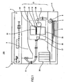
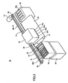
- Fig. 3 is a perspective view showing a recording portion 3 including a printing part (image forming part) 10 of the image forming apparatus 100.
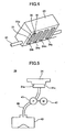
- Fig. 4 is a perspective view observed from a bottom side of a carriage 23 of the image forming apparatus 100.
- the image forming apparatus 100 is a copy machine.
- the image forming apparatus 100 has a main body 1 including an image reading portion 2 (e.g. scanner) for reading an image from a document, the recording portion 3 for forming an image on a recording medium (hereinafter referred to as "paper") P, and a sheet-feed cassette portion 4 for feeding the paper P to the recording portion 3.
- the papers P stored in the sheet-feed cassette portion 4 are separated and fed sheet-by-sheet by a sheet-feed roller 5 and a separating pad 6. Then, the paper P is conveyed to the printing part 10 via a conveying path 7. In the printing part 10, an image is recorded (formed) on the paper P.
- the paper P on which the image is formed is conveyed to a sheet-discharge path 8. Then, the paper P is discharged from the sheet-discharge path 8. Then, the discharged paper P is stacked on a sheet-stacking part 9.
- the printing part 10 includes a carriage 23 supported by a carriage guide (guiding rod) 21 and a guide stay (not shown) for moving in a main scanning direction.
- the carriage 23 is driven to move in the main scanning direction by a main scan motor 27 via a timing belt 30 spanning between a driving pulley 28 and a driven pulley 29.
- Liquid jet heads 24k, 24c, 24m, and 24y (also collectively referred to as “recording head 24") for ejecting inks corresponding to black (K), cyan (C), magenta (M), and yellow (Y) are mounted on the carriage 23.
- each liquid jet head 24 has plural liquid ejecting nozzles 31 arranged in two rows (nozzle rows) 32.
- the nozzle rows 32 are arranged in a direction orthogonal to the main scanning direction (moving direction of the carriage 23).
- the plane (nozzle plane) 31a of the liquid jet head 24 on which the nozzles 31 are formed faces downward. Furthermore, ink of a corresponding color is supplied to each recording head 24 from an ink cartridge 26.
- the recording head 24 may be, for example, a piezoelectric type recording head which uses a piezoelectric element (pressure generating part or actuating part) for ejecting ink droplets by changing the volume in an ink flow channel (stress generating chamber) by changing the shape of a vibration plate that forms the wall of the ink flow channel.
- the recording head 24 may be a thermal type recording head which uses a heat resistor for ejecting ink droplets by heating ink inside an ink flow channel and generating bubbles which create the pressure for ejecting the ink droplets.
- the recording head 24 may be an electrostatic type recording head 24 for ejecting ink droplets by arranging a vibration plate and an electrode facing each other and changing the volume in an ink flow channel by changing the shape of the vibration plate by generating an electrostatic force between the vibration plate and the electrode.
- an endless conveying belt 35 is provided below the carriage 23 for carrying the paper P thereon by using, for example, an electrostatic attracting force.
- the conveying belt 35 spans between a driving roller 36 and a driven roller 37. By rotating the conveying belt 35, the paper P is conveyed in a direction perpendicularly intersecting the main scanning direction.
- a maintenance/recovery mechanism (maintenance/recovery apparatus) 38 is provided in a non-printing area on one end of the moving direction of the carriage 23 as shown in Figs. 2 and 3 .
- the recovery mechanism is for maintaining and recovering the condition of the nozzles 31 of the recording head 24.
- the recovery mechanism 38 includes a blank ejection receiver 39 for receiving droplets (droplets not used for recording) in a non-printing area on the other end of the moving direction of the carriage 23.
- the maintenance/recovery mechanism 38 includes plural cap members 41 (in this example, an absorbing cap 41a and three moisture retention caps 42b) for capping (covering) each nozzle plane 31a of the recording head 24, a wiper blade (wiping member) 42 for wiping the nozzle plane 31a of the recording head 24, and a blank ejection receiver (first discharging part) 43.
- the absorbing cap 41a is connected to an absorbing pump (suction pump) 45 that uses a pumping tube. Thereby, waste ink can be discharged from the absorbing pump 45 to a waste ink container 40 situated below the absorbing pump 45 via a discharge tube (second discharging part) 46.
- a bottom part of the blank ejection receiver 43 is positioned facing the waste liquid container 40 for allowing unwanted waste liquid (ejected by blank-ejection) to be discharged (dropped) into the waste liquid container 40. Furthermore, four openings 39a are formed in the blank ejection receiver 39.
- a part in the maintenance/recovery mechanism 38 for performing a head absorption (head suction) operation (an operation of forcing ink to be discharged from the nozzles 31) is described with reference to Fig. 5 .
- the nozzle plane 31a of the recording head 24 is sealed with the absorbing cap 41 a and the absorbing pump 41a is rotated with an absorbing pump motor 47, to thereby create a vacuum (negative pressure) state in a space formed inside the recording head 24 by the nozzle plane 31a and the absorbing cap 41a.
- the negative pressure allows the ink inside the nozzles 31 to be suctioned and discharged from the nozzles 31.
- the discharged waste liquid is pumped by the absorbing pump 45 and discharged to the waste liquid container 40.
- a first example of the waste liquid container 40 includes a first container 101 having a single waste liquid inlet 104 into which the waste liquid is introduced and a second container 102 communicating with the first container 101.
- the first and second containers 101, 102 are detachably connected to each other by a communication path 103.
- the viscosity (liquidity) of the waste liquid introduced from the waste liquid inlet 104 differs depending on various conditions (e.g., type of output image, number of output pages, frequency of usage) or the environment where the image forming apparatus is installed.
- the waste liquid having high viscosity remains in the first container 101.
- the waste liquid having low viscosity is guided from the first container 101 to the second container 102 via the communication path 103.
- the waste liquid having low viscosity is stored in the second container 102.
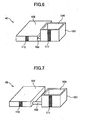
- a second example of the waste liquid container 40 has the communication path 103 shaped as a tube.
- the communication path 103 by forming the communication path 103 with a tube made of rubber material (e.g., silicone), the first and second containers 101, 102 can be positioned apart from each other.
- a tube made of rubber material e.g., silicone
- a third example of the waste liquid container 40 has the second container 102 formed with a long length in view of the high liquidity of the waste liquid having low viscosity.
- the second container 102 may be formed in other shapes matching the space inside the image forming apparatus 100.
- the second container 102 may be formed in a bag-like shape.
- the following fourth through sixth reference examples of the waste liquid container 40 have the second container 102 provided at a position lower than the first container 101.
- the first and second containers 101,102 are detachably connected to each other by a communication path 103.
- the waste liquid having low viscosity can quickly flow from the first container 101 into the second container 102.
- a fourth example of the waste liquid container 40 has a side bottom part of the first container 101 connected to a side upper part of the second container 102 via the communication path 103.
- a fifth example of the waste liquid container 40 has a bottom part of the first container 101 connected to a top part of the second container 102 via the communication path 103 by superposing a portion of the first container 101 on a portion of the second containers 102 via the communication path 103.
- a sixth example of the waste liquid container 40 has the communication path 103 shaped as a tube for connecting the first and second containers 101,102 that are positioned apart from each other.
- the following seventh and eighth examples of the waste liquid container 40 have the second container 102 provided immediately below the first container 101 and have the first and second containers 101, 102 detachably connected to each other by the communication path 103.
- waste liquid having high viscosity accumulateating waste liquid
- waste liquid having low viscosity is contained in the second container 102.
- the communication path 103 is located at a position deviating from the area where the waste liquid dropping from the waste liquid inlet 104 lands (landing area).
- waste liquid container 40 is described in further detail with reference to Fig. 14 .
- waste ink (waste liquid not contributing to image formation) 121 discharged from the blank ejection receiver 43 or the discharge tube 46 is introduced into the waste liquid inlet 104, solid waste matter 122 contained in the waste ink 121 accumulates inside the first container 101 and liquid waste matter 123 contained in the waste ink 121 flows into the second container 102 via the communication path 103.
- a first sensor (first detecting part) 111 including a capacitance type sensor (electric field sensor or sensor electrode) is provided on the sidewalls of the first container 101 and a second sensor (second detecting part) 112 also including a capacitance type sensor (electric field sensor or sensor electrode) is provided on the side walls of the second container 102.
- the first and second sensors 111, 112 have sensor electrodes provided on the entire side walls of the first and second containers 101,102 with respect to the height direction of the first and second containers 101, 102.
- Fig. 15 is a schematic diagram for describing a principle of a detecting operation performed by the capacitance type sensor of the first sensor 111.
- a pair of sensor electrodes 111a, 111b is provided in parallel at the oppositely facing outer sidewalls of the first container 101.
- the solid waste matter 122 contained in the waste ink 121 accumulates inside the first container 101.
- the capacitance between the sensor electrodes 111a and 111b is measured by applying an alternating current electric field V to the sensor electrodes 111a, 111b.
- a pair of sensor electrodes may be provided to oppositely facing outer sidewalls of the second container 102, and the capacitance between the pair of sensor electrodes can be measured. Accordingly, since the measured value of the capacitance directly corresponds to the amount of the liquid waste matter 123 (not solidified) in the second container 102, the height of the liquid waste matter 123 contained in the second container 102 can be detected by referring to the measured value.
- the pairs of sensor electrodes may be provided on the same sidewall. Even in a case where the pairs of sensor electrodes are provided to the same sidewall, an electric field, which covers the space inside the first container 101 or the second container 102, can be generated. Accordingly, the status of the waste matter 122, 123 in the inside space of the first and second containers 101, 102 can be detected.
- the first container 101 is determined to be full.
- the second sensor 112 detects that the fluid waste matter 112 in the second container 102 has reached a predetermined height, the second container is determined to be full.
- the waste liquid container 40 may be determined to be full.
- the waste liquid container 40 is configured having a first container provided with a single waste liquid inlet and a second container detachably connected in communication with respect to the first container, only the container detected to be full needs to be replaced. Thereby, the space of the waste liquid container 40 can be efficiently used.
- first and second detecting parts in the first and second containers, full containers can be detected separately. Thereby, each container can be replaced at a suitable timing.
- plural first sensors 111 are provided on the entire sidewall of the first container 101 while a wide second sensor 112 is provided on the sidewall of the second container 102.
- a wide second sensor 112 is provided on the sidewall of the second container 102.
- plural first sensors 111 are provided on the entire sidewall of the first container 101 while plural second sensors 112 are also provided on the entire sidewall of the second container 102. With this configuration, the shape of the waste matter of the entire waste liquid container 40 can be detected.
- plural first sensors 111 are provided on the entire four sidewalls of the first container 101 while plural second sensors 112 are provided on an the entire single sidewall of the second container 102.
- the three-dimensional shape and the peak of the solid waste matter 122 accumulated in the first container 101 can be detected.
- the waste liquid container 40 includes the capacitance type first sensor 111 and an optical sensor 113 acting as the second detecting part attached to a top wall of the second container 102.
- Figs. 20 and 21 are schematic diagrams for describing the optical sensor 113.
- the optical sensor 113 includes a reflection type photosensor 114, an absorbing member 116 for absorbing waste ink, and a case 115 for holding the photosensor 114 and the absorbing member 116.
- the absorbing member 116 is a material having a characteristic of easily absorbing liquid waste ink (e.g., felt, sponge) and having a color capable of sufficiently reflecting light (e.g., white).
- the photosensor 114 is attached to the case 115 so that a certain distance is kept from the absorbing member 116.
- the case 115 provides a sealed space between the absorbing member 116 and the photosensor 114 so that light or ink mist can be prevented from entering the space.
- ink mist can be prevented from adhering to a sensor surface of the photosensor 114. Thereby, erroneous detection by the photosensor 114 can be prevented. Furthermore, by sealing the space, only the light reflected from the absorbing member 116 is detected by the photosensor 114. Thereby, the photosensor 114 can satisfactorily determine whether waste ink is absorbed by the absorbing member 116.
- the photosensor 114 has claw parts which pressingly engage the upper opening part of the case 115 when the photosensor 114 is inserted in the upper opening part of the case 115. Thereby, the photosensor 114 can be attached to the case 115.
- the absorbing member 116 is fixed to an absorbing member holding part of the case 115 by using, for example, an adhesive agent.
- the absorbing member 116 is attached to the top wall of the second container 102 in a manner that the absorbing member 116 faces the inside of the second container 102 and absorbs the waste ink inside the second container 102.
- the liquid waste matter 123 is absorbed by the absorbing member 116 as its height inside the second container 102 increases, and the color of the absorbing member 116 changes as the liquid waste matter 123 is absorbed. Accordingly, the optical sensor 114 can detect whether the second container 102 is full.
- Fig. 22 is a block diagram of a portion related to controls performed by the main control part 201 for detecting a full waste liquid container 40 and changing a waste ink discharging position.
- the main control part 201 is for performing control of the entire image forming apparatus 100 including control for changing a waste liquid discharging position according to an embodiment of the present invention.
- the main control part 201 includes, for example, a CPU, a ROM, a RAM, an I/O device, and a rewritable non-volatile memory.
- the main control part 201 moves the carriage 23 in a desired direction for a prescribed amount by rotating the main scan motor 27 via a driving circuit 202.
- the main control part 201 drives the recording head 24 for ejecting liquid droplets (e.g., ink) via a driving circuit 203.
- the main control part 201 drives the absorbing pump 45 by rotating the absorbing pump motor 47 via a driving circuit 204.
- the main control part 201 also determines whether the first and second containers 101, 102 of the waste liquid container 40 are in a full state or a nearly-full (almost full container) by receiving detection signals indicative of the status of the waste liquid inside the waste liquid container 40 from the first and second sensors 111, 112 and comparing the detection results with a predetermined threshold(s). The main control part 201 also determines whether the waste liquid container 40 is mounted by receiving detection signals from a tank mount sensor 119.
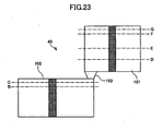
- thresholds that are set in correspondence with the first sensor 111 of the first container 101 and the second sensor 112 of the second container 102 are described with reference to Fig. 23 .
- One or more thresholds are set with respect to the shape (capacity) of the first container 101 of the waste liquid container 40 beforehand.
- the main control part 201 may control (limit) usage of the image forming apparatus 100 or change a position for discharging waste ink.
- thresholds D, E, F, G are set in correspondence with the height (position) of the solid waste matter 122 detected by the first sensor 111 (corresponding heights satisfying a relationship of D ⁇ E ⁇ F ⁇ G).
- thresholds B and C are set in correspondence with the height (position) of the liquid waste matter 123 detected by the second sensor 112 (corresponding heights satisfying a relationship of B ⁇ C).
- the settings of the thresholds are not limited to those of the above-described example.
- the operation determines whether the height of the solid waste matter 122 of the first container 101 detected by the first sensor 111 is equal to or greater than the threshold D (H1 ⁇ D) (S501). In a case where the height of the solid waste matter 122 has not reached the threshold D (No in S501), it is determined whether the height of the liquid waste matter 123 of the second container 102 detected by the second sensor 112 is equal to or greater than the threshold B (H2 ⁇ B) (S506) If the height of the liquid waste matter 123 is less than the threshold B, the operation returns to the beginning.
- the height of the solid waste matter 122 is equal to or greater than the threshold D (Yes in S501)
- the height H1 is less than the threshold E, that is, in a case where the height H1 is equal to or greater than the threshold D but less than the threshold E (D ⁇ H1 ⁇ E)
- the position for discharging waste ink into the first container 101 is changed to a predetermined first discharge position (variable position ⁇ ) (S601).
- the height H1 is equal to or greater than the threshold E
- the height H1 is less than the threshold F, that is, in a case where the height H1 is equal to or greater than the threshold E but less than the threshold F (E ⁇ H1 ⁇ F)
- the position for discharging waste ink into the first container 101 is changed to a predetermined second discharge position (variable position ⁇ ) (S602).
- the height H1 is equal to or greater than the threshold F
- the height H1 is less than the threshold G, that is, in a case where the height H1 is equal to or greater than the threshold F but less than the threshold G (F ⁇ H1 ⁇ G)
- a nearly-full container operation is performed.
- the nearly-full container operation includes, for example, a process for indicating that the first container 101 of the waste liquid container 40 is nearly full on a display of a control panel of the image forming apparatus 100 or reporting that the first container 101 of the waste liquid container 40 is nearly full to a printer driver of a host computer.
- the first container 101 is full (full container).
- a full-container operation includes, for example, a process of shutting down (stopping) operations of the image forming apparatus 100 along with a process for indicating that the first container 101 of the waste liquid container 40 should be replaced on a display of a control panel of the image forming apparatus 100 or reporting that the first container 101 of the waste liquid container 40 should be replaced to a printer driver of a host computer.
- the second container 102 is nearly full (nearly-full container).
- a nearly-full container operation is performed.
- the nearly-full container operation includes, for example, a process for indicating that the second container 102 of the waste liquid container 40 is nearly full on a display of a control panel of the image forming apparatus 100 or reporting that the second container 102 of the waste liquid container 40 is nearly full to a printer driver of a host computer.
- the height H2 is not less than the threshold C, that is, in a case where the height H2 is equal to or greater than the threshold C, it is determined that the second container 102 is full (full container).
- a full-container operation is performed.
- the full-container operation includes, for example, a process of shutting down (stopping) operations of the image forming apparatus 100 along with a process for indicating that the second container 102 of the waste liquid container 40 should be replaced on a display of a control panel of the image forming apparatus 100 or reporting that the second container 102 of the waste liquid container 40 should be replaced to a printer driver of a host computer.
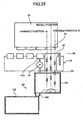
- the carriage 23 In a case of changing a blank ejection position according to a predetermined threshold, the carriage 23 is controlled to stop at a suitable position.
- the stopping position of the carriage 23 is controlled according to data of the waste liquid (waste ink) accumulated in the first container 101 of the waste liquid container 40. For example, the carriage 23 stops at a position where waste liquid is discharged (dropped) on an area where the height of the waste liquid is lowest.
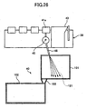
- a distal end of a discharging part of the discharge tube 46 is inclined toward the first container 101 of the waste liquid container 26.
- the rotational speed of the absorbing pump motor 47 that drives the absorbing pump 45 the discharge rate of the waste liquid 121 is changed, to thereby change the landing area (impact area) of the discharged waste liquid 121.
- waste liquid can be prevented from accumulating in a single area of the first container 101. Accordingly, the first container 101 of the waste liquid container 40 can be efficiently used.
- changing of the discharge position can be achieved with a simple configuration in which the discharge tube 46 is inclined (tilted) at a suitable angle.
- Fig. 27 is a schematic diagram showing a detachable attachment structure of the sensor electrode 111a of the first sensor 111 according to an embodiment of the present invention.
- the sensor electrode 111a included in the first sensor 111 is formed as a thin film.
- the sensor electrode 111a is formed of a conductive material such as aluminum, copper, nickel, or iron.
- the sensor electrode 111a may be fixed to the first container 101 by using an adhesive agent or double-faced tape, it is preferable to detachably attach the sensor electrode 11a to the first container 101 by providing claws 131 at the sidewall of the first container 101 and inserting the claws 131 into corresponding holes 130 formed in the sensor electrode 111a.
- the sensor electrode provided in the second sensor 112 may be configured in the same manner as the first sensor 111.
- the waste liquid container 40 and the sensors 111, 112 can contribute to recycling.
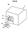
- Fig. 28 is a perspective view showing a detachable attachment structure of the waste liquid container 40.
- Fig. 29 is a schematic diagram showing a mounting (attaching) part of the waste liquid container 40.
- the waste liquid container 40 can be removed out from the main body 1 of the image forming apparatus 100 by removing an outer cover part provided at the back of the main body 1. As shown in Fig. 29 , a tank detection sensor 119 is provided to an attachment part 120 provided inside the main body 1 for detecting the presence of the waste liquid container 40.
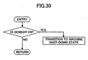
- the main control part 201 determines whether the tank detection sensor 119 is "on".
- the tank detection sensor 119 is "on" when the waste liquid container 40 is detached from the attachment part 120.
- the image forming apparatus 100 shifts to a shut-down state.
- the waste liquid container 40 (including the first container 101 or the second container 102) is detachable from the main body 1 of the image forming apparatus 100, the waste liquid container 40 can be re-attached after eliminating stored waste liquid or replaced with a new waste liquid container. This facilitates maintenance of the image forming apparatus 100. Furthermore, since the presence of the waste liquid container 40 can be detected, waste liquid can be prevented from being erroneously discharged in a state where the waste liquid container 40 is not attached to the image forming apparatus 100. Accordingly, the surrounding of the waste liquid container 40 can be prevented from being stained by waste liquid.
Description
- The present invention relates to a waste liquid container and an image forming apparatus.
- As for known image forming apparatuses, there are printers, facsimile machines, copiers, and multi-function machines. One example of such image forming apparatuses is a liquid jet recording apparatus.(e.g., inkjet recording apparatus). The liquid jet recording apparatus performs an image forming (also referred to as "recording", "printing" and the like) operation by using a recording head that ejects droplets of recording liquid (ink droplets) to a medium (e.g., paper, OHP sheet, also referred to as "recording medium") onto which the ejected liquid droplets can adhere. The liquid jet recording apparatus includes, for example, a serial type image forming apparatus that forms images by ejecting liquid droplets while moving the recording head in a main scanning direction or a line type image forming apparatus that forms images by ejecting liquid droplets without moving the recording head.
- It is to be noted that the medium on which liquid is ejected from the image forming apparatus includes materials such as paper, string, fiber, fabric, leather, metal, plastic, glass, wood, and ceramic. Furthermore, the term "image formation" not only includes forming images that have a meaning (e.g., letters, shapes) on a medium but also includes forming images having no particular meaning (e.g., patterns). Furthermore, the term "liquid" not only includes recording liquid and ink, but also includes any liquid which can be used to form images. Furthermore, the term "liquid jetting apparatus" includes an apparatus that ejects liquid from a liquid jet head.
- The image forming apparatus including the liquid jetting apparatus may be provided with a maintenance/recovery mechanism for maintaining/recovering the performance of a recording head from which liquid (e.g., ink) is ejected. The maintenance/recovery mechanism seals a nozzle plane (plane of the recording head in which nozzles are formed) of the recording head with a cap member and connects the cap member to an absorbing pump having a pumping tube, and drives the absorbing pumping, to thereby forcibly discharge ink from the nozzles of the recording head. Furthermore, the maintenance/recovery mechanism performs blank ejection for ejecting ink droplets that do not contribute to image formation.
- By operating the maintenance/recovery mechanism, waste liquid not contributing to image formation is discharged to a waste liquid container provided in the image forming apparatus for storing the waste liquid (also referred to as "waste liquid containing unit", "waste liquid tank", and "waste ink tank"). The image forming apparatus stops operations when the waste liquid container is full or nearly full.
- As a waste liquid container according to a related art example, Japanese Registered Patent No.
85143 Patent Document 1") discloses a waste liquid container including a reservoir area for storing waste ink, an ink receiving area for receiving waste ink discharged from a pumping apparatus and guiding the waste ink to the reservoir area, a non-reservoir area situated next to the ink receiving area for removing the waste liquid, a first ink absorbing member provided in the ink receiving area for absorbing waste ink, and a second ink absorbing member provided in the reservoir area for absorbing waste ink. - Japanese Laid-Open Patent Application No.
2006-137079 Patent Document 2") discloses a waste liquid container for containing waste liquid by separately containing accumulated matter and liquid matter included in the waste liquid. This container is provided with a notch part and a space into which the waste liquid is introduced. The accumulated matter is contained in the space, and the liquid matter is absorbed by an absorbing member. - Furthermore, Japanese Laid-Open Patent Application No.
2000-85143 Patent Document 3") discloses a waste ink tank able to detect whether the waste ink tank is full. This waste ink tank has a waste ink inlet at one end of an upper wall of the waste ink tank and a detection window at the other end. A white sponge and an optical detection sensor are provided at a lower part of the detection window for detecting whether the optical reflectance of the sponge is equal to or less than a predetermined value as the color of the sponge changes to black as the waste ink is absorbed by the white sponge. The waste ink tank detects that the tank is full when hardly any light is incident on the optical sensor. - Furthermore, Japanese Laid-Open Patent Application No.
2000-141704 Patent Document 4") discloses a waste ink collecting mechanism having a part for counting the number of times performing a maintenance operation. Accordingly, it is determined whether a tank is full by estimating the amount of waste ink based on the counted results and comparing the estimated amount with a predetermined amount. - Furthermore, Japanese Laid-Open Patent Application No.
2004-136550 Patent Document 5") discloses an inkjet recording apparatus that determines whether a waste ink tank is full by estimating the total amount of waste ink discharged to the waste ink tank and comparing the estimated total amount with a reference value that is increased along with the passing of time. - Furthermore, Japanese Laid-Open Patent Application No.
2006-159465 Patent Document 6") discloses an image forming apparatus including a waste liquid container configured to store accumulated ink in the vicinity of a waste liquid inlet and absorb liquid waste ink by providing an absorbing member at areas other than the vicinity of the waste liquid inlet. The image forming apparatus detects whether its tank is full by detecting the accumulated ink by calculating the number of times performing a maintenance operation and comparing the calculation results with a reference value. - Since the waste liquid containers disclosed in
Patent Documents - As described in
Patent Documents Patent Document 3 configured to determine whether its tank is full on the premise that the waste ink has fluidity may be unable to determine that its tank is full due to the accumulated waste liquid overflowing from its waste liquid inlet. - Furthermore, with the waste liquid containers disclosed in
Patent Documents 4 through 6, each of which determines whether its tank is full by estimating the amount of waste liquid by comparing it with a predetermined threshold, the precision of the determination largely differs depending on the precision of the calculating part (threshold value) since determination is made without measuring the actual amount of waste ink. Therefore, in a case where the criterion for the determination is assumed with a high safety margin, the tank may be determined as being full at an early stage even if there is still sufficient room available for containing the waste liquid. As a result, the waste container cannot be sufficiently used (short service life). On the other hand, overflow of the waste liquid may occur in a case where the criterion for the determination is assumed with a low safety margin or a case where the waste liquid tank is used under conditions (environment) different from the conditions assumed for obtaining the threshold value. -
JP 08-267781 A claim 1 and shows a waste ink collection arrangement having a main tank and an overflow tank. The overflow tank is connected to the top of the main tank. Waste ink is supplied to the main tank and when that is full is forced by capillary action into the overflow tank. -
JP 2001310487 A -
JP 2007160,871 A -
JP 2003011,394 A - The present invention may provide a waste liquid container according to
claim 1 and an image forming apparatus according toclaim 8 that substantially obviate one or more of the problems caused by the limitations and disadvantages of the related art. - In accordance with the invention, there is provided a waste liquid container and an image forming apparatus as defined in the appended claims.
- Other objects, features and advantages of the present invention will become more apparent from the following detailed description of exemplary embodiments when read in conjunction with the accompanying drawings, in which:
-
Fig. 1 is a schematic view showing an overall configuration of an exemplary image forming apparatus; -
Fig. 2 is a right side view of the image forming apparatus shown inFig. 1 ; -
Fig. 3 is a perspective view showing a recording portion including a printing part (image forming part) of an exemplary image forming apparatus; -
Fig. 4 is a perspective view observed from a bottom side of a carriage of an exemplary image forming apparatus; -
Fig. 5 is a schematic diagram for describing a head absorption (head suction) operation; -
Fig. 6 is a schematic diagram showing a first reference example of a waste liquid container; -
Fig. 7 is a schematic diagram showing a second reference example of a waste liquid container; -
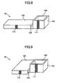
Fig. 8 is a schematic diagram showing a third reference example of a waste liquid container; -
Fig. 9 is a schematic diagram showing a fourth reference example of a waste liquid container; -
Fig. 10 is a schematic diagram showing a fifth reference example of a waste liquid container; -
Fig. 11 is a schematic diagram showing a sixth reference example of a waste liquid container; -
Fig. 12 is a schematic diagram showing a seventh reference example of a waste liquid container; -
Fig. 13 is a schematic diagram showing a eighth reference example of a waste liquid container; -
Fig. 14 is a schematic diagram for describing storing of waste liquid by a waste liquid container according to an embodiment of the present invention; -
Fig. 15 is a schematic diagram for describing a principle of a detecting operation performed by a capacitance type sensor of a first sensor according to an embodiment of the present invention; -
Fig. 16 is a schematic diagram showing a first example of a waste liquid container according to an embodiment of the present invention; -
Fig. 17 is a schematic diagram showing a second example of a waste liquid container according to an embodiment of the present invention; -
Fig. 18 is a schematic diagram showing a third example of a waste liquid container according to an embodiment of the present invention; -
Fig. 19 is a schematic diagram for describing an exemplary waste liquid container; -
Fig. 20 is a schematic view for describing an exemplary second detecting part; -
Fig. 21 is a disassembled schematic view for describing the exemplary second detecting part; -
Fig. 22 a block diagram showing a portion related to controls performed by an exemplary main control part for detecting a full waste liquid container and changing a waste ink discharging position; -
Fig. 23 is a schematic diagram for describing thresholds set for an exemplary waste liquid container; -
Fig. 24 is a flowchart for describing an examplary waste liquid discharge position changing operation; -
Fig. 25 is a schematic diagram for describing an example of a blank ejection position changing operation according to an embodiment of the present invention; -
Fig. 26 is a schematic diagram for describing another example of a blank ejection position changing operation according to an embodiment of the present invention; -
Fig. 27 is a schematic diagram showing a detachable attachment structure of a sensor electrode of an examplary first sensor; -
Fig. 28 is a perspective view showing a detachable attachment structure of an examplary waste liquid container; -
Fig. 29 is a schematic diagram showing a mounting (attaching) part of an examplary waste liquid container; -
Fig. 30 is a flowchart showing an examplary tank detecting operation. - An exemplary image forming apparatus is described with reference to
Figs.1 through 4 .Fig.1 is a schematic view showing an overall configuration of an exemplaryimage forming apparatus 100.Fig. 2 is a right side view of theimage forming apparatus 100 shown inFig. 1 .Fig. 3 is a perspective view showing arecording portion 3 including a printing part (image forming part) 10 of theimage forming apparatus 100.Fig. 4 is a perspective view observed from a bottom side of acarriage 23 of theimage forming apparatus 100. - The
image forming apparatus 100 is a copy machine. Theimage forming apparatus 100 has amain body 1 including an image reading portion 2 (e.g. scanner) for reading an image from a document, therecording portion 3 for forming an image on a recording medium (hereinafter referred to as "paper") P, and a sheet-feed cassette portion 4 for feeding the paper P to therecording portion 3. In theimage forming apparatus 100, the papers P stored in the sheet-feed cassette portion 4 are separated and fed sheet-by-sheet by a sheet-feed roller 5 and aseparating pad 6. Then, the paper P is conveyed to theprinting part 10 via a conveying path 7. In theprinting part 10, an image is recorded (formed) on the paper P. Then, the paper P on which the image is formed is conveyed to a sheet-discharge path 8. Then, the paper P is discharged from the sheet-discharge path 8. Then, the discharged paper P is stacked on a sheet-stackingpart 9. - As shown in
Fig. 3 , theprinting part 10 includes acarriage 23 supported by a carriage guide (guiding rod) 21 and a guide stay (not shown) for moving in a main scanning direction. Thecarriage 23 is driven to move in the main scanning direction by amain scan motor 27 via a timing belt 30 spanning between a drivingpulley 28 and a drivenpulley 29. - Liquid jet heads 24k, 24c, 24m, and 24y (also collectively referred to as "recording
head 24") for ejecting inks corresponding to black (K), cyan (C), magenta (M), and yellow (Y) are mounted on thecarriage 23. - As shown in
Fig. 4 , eachliquid jet head 24 has pluralliquid ejecting nozzles 31 arranged in two rows (nozzle rows) 32. Thenozzle rows 32 are arranged in a direction orthogonal to the main scanning direction (moving direction of the carriage 23). The plane (nozzle plane) 31a of theliquid jet head 24 on which thenozzles 31 are formed faces downward. Furthermore, ink of a corresponding color is supplied to eachrecording head 24 from anink cartridge 26. - The
recording head 24 may be, for example, a piezoelectric type recording head which uses a piezoelectric element (pressure generating part or actuating part) for ejecting ink droplets by changing the volume in an ink flow channel (stress generating chamber) by changing the shape of a vibration plate that forms the wall of the ink flow channel. Alternatively, therecording head 24 may be a thermal type recording head which uses a heat resistor for ejecting ink droplets by heating ink inside an ink flow channel and generating bubbles which create the pressure for ejecting the ink droplets. Alternatively, therecording head 24 may be an electrostatictype recording head 24 for ejecting ink droplets by arranging a vibration plate and an electrode facing each other and changing the volume in an ink flow channel by changing the shape of the vibration plate by generating an electrostatic force between the vibration plate and the electrode. - Furthermore, an endless conveying
belt 35 is provided below thecarriage 23 for carrying the paper P thereon by using, for example, an electrostatic attracting force. The conveyingbelt 35 spans between a drivingroller 36 and a drivenroller 37. By rotating the conveyingbelt 35, the paper P is conveyed in a direction perpendicularly intersecting the main scanning direction. - Furthermore, a maintenance/recovery mechanism (maintenance/recovery apparatus) 38 is provided in a non-printing area on one end of the moving direction of the
carriage 23 as shown inFigs. 2 and3 . The recovery mechanism is for maintaining and recovering the condition of thenozzles 31 of therecording head 24. Therecovery mechanism 38 includes ablank ejection receiver 39 for receiving droplets (droplets not used for recording) in a non-printing area on the other end of the moving direction of thecarriage 23. - The maintenance/
recovery mechanism 38 includes plural cap members 41 (in this example, an absorbingcap 41a and three moisture retention caps 42b) for capping (covering) eachnozzle plane 31a of therecording head 24, a wiper blade (wiping member) 42 for wiping thenozzle plane 31a of therecording head 24, and a blank ejection receiver (first discharging part) 43. The absorbingcap 41a is connected to an absorbing pump (suction pump) 45 that uses a pumping tube. Thereby, waste ink can be discharged from the absorbingpump 45 to awaste ink container 40 situated below the absorbingpump 45 via a discharge tube (second discharging part) 46. Furthermore, a bottom part of theblank ejection receiver 43 is positioned facing thewaste liquid container 40 for allowing unwanted waste liquid (ejected by blank-ejection) to be discharged (dropped) into thewaste liquid container 40. Furthermore, fouropenings 39a are formed in theblank ejection receiver 39. - Next, a part in the maintenance/
recovery mechanism 38 for performing a head absorption (head suction) operation (an operation of forcing ink to be discharged from the nozzles 31) is described with reference toFig. 5 . - At a certain timing or when the viscosity of the ink inside the
nozzles 31 of therecording head 24 increases to a level preventing ink droplets from being normally ejected, thenozzle plane 31a of therecording head 24 is sealed with the absorbingcap 41 a and the absorbingpump 41a is rotated with an absorbingpump motor 47, to thereby create a vacuum (negative pressure) state in a space formed inside therecording head 24 by thenozzle plane 31a and the absorbingcap 41a. The negative pressure allows the ink inside thenozzles 31 to be suctioned and discharged from thenozzles 31. The discharged waste liquid is pumped by the absorbingpump 45 and discharged to thewaste liquid container 40. - Next, the
waste liquid container 40 is described in detail with reference toFigs. 6 through 8 . - As shown in
Fig. 6 , a first example of thewaste liquid container 40 includes afirst container 101 having a singlewaste liquid inlet 104 into which the waste liquid is introduced and asecond container 102 communicating with thefirst container 101. The first andsecond containers communication path 103. - The viscosity (liquidity) of the waste liquid introduced from the
waste liquid inlet 104 differs depending on various conditions (e.g., type of output image, number of output pages, frequency of usage) or the environment where the image forming apparatus is installed. The waste liquid having high viscosity remains in thefirst container 101. By providing an inclination (not shown) at the bottom of thefirst container 101, the waste liquid having low viscosity is guided from thefirst container 101 to thesecond container 102 via thecommunication path 103. Thus, the waste liquid having low viscosity is stored in thesecond container 102. - As shown in
Fig. 7 , a second example of thewaste liquid container 40 has thecommunication path 103 shaped as a tube. For example, by forming thecommunication path 103 with a tube made of rubber material (e.g., silicone), the first andsecond containers - As shown in
Fig. 8 , a third example of thewaste liquid container 40 has thesecond container 102 formed with a long length in view of the high liquidity of the waste liquid having low viscosity. Thesecond container 102 may be formed in other shapes matching the space inside theimage forming apparatus 100. For example, thesecond container 102 may be formed in a bag-like shape. - Next, another type of
waste liquid container 40 is described in detail with reference toFigs. 9 through 11 . - As shown in
Figs. 9 through 11 , the following fourth through sixth reference examples of thewaste liquid container 40 have thesecond container 102 provided at a position lower than thefirst container 101. The first and second containers 101,102 are detachably connected to each other by acommunication path 103. By positioning thesecond container 102 lower than thefirst container 101, the waste liquid having low viscosity can quickly flow from thefirst container 101 into thesecond container 102. - As shown in
Fig. 9 , a fourth example of thewaste liquid container 40 has a side bottom part of thefirst container 101 connected to a side upper part of thesecond container 102 via thecommunication path 103. - As shown in
Fig. 10 , a fifth example of thewaste liquid container 40 has a bottom part of thefirst container 101 connected to a top part of thesecond container 102 via thecommunication path 103 by superposing a portion of thefirst container 101 on a portion of thesecond containers 102 via thecommunication path 103. - As shown in
Fig. 11 , a sixth example of thewaste liquid container 40 has thecommunication path 103 shaped as a tube for connecting the first and second containers 101,102 that are positioned apart from each other. - Next, a third type of
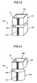
waste liquid container 40 is described in detail with reference toFigs. 12 and 13 . - As shown in
Figs. 12 and 13 , the following seventh and eighth examples of thewaste liquid container 40 have thesecond container 102 provided immediately below thefirst container 101 and have the first andsecond containers communication path 103. With this configuration of the seventh and eighth examples of thewaste liquid container 40, waste liquid having high viscosity (accumulating waste liquid) remains in thefirst container 101 and waste liquid having low viscosity is contained in thesecond container 102. In both examples of thewaste liquid container 40 of the third type, thecommunication path 103 is located at a position deviating from the area where the waste liquid dropping from thewaste liquid inlet 104 lands (landing area). - Next, the
waste liquid container 40 is described in further detail with reference toFig. 14 . In a case where waste ink (waste liquid not contributing to image formation) 121 discharged from theblank ejection receiver 43 or thedischarge tube 46 is introduced into thewaste liquid inlet 104,solid waste matter 122 contained in thewaste ink 121 accumulates inside thefirst container 101 andliquid waste matter 123 contained in thewaste ink 121 flows into thesecond container 102 via thecommunication path 103. - In the
waste liquid container 40 as described above, a first sensor (first detecting part) 111 including a capacitance type sensor (electric field sensor or sensor electrode) is provided on the sidewalls of thefirst container 101 and a second sensor (second detecting part) 112 also including a capacitance type sensor (electric field sensor or sensor electrode) is provided on the side walls of thesecond container 102. The first andsecond sensors second containers -
Fig. 15 is a schematic diagram for describing a principle of a detecting operation performed by the capacitance type sensor of thefirst sensor 111. A pair ofsensor electrodes first container 101. As described above, thesolid waste matter 122 contained in thewaste ink 121 accumulates inside thefirst container 101. With this accumulation, the capacitance between thesensor electrodes sensor electrodes sensor electrodes sensor electrode 111a and thesensor electrode 111b). Accordingly, since the measured value of the capacitance directly corresponds to the amount of thesolid waste matter 122 accumulated in thefirst container 101, the height of thesolid waste matter 122 accumulated in thefirst container 101 can be detected by referring to the measured value. - Likewise, a pair of sensor electrodes (not shown) may be provided to oppositely facing outer sidewalls of the
second container 102, and the capacitance between the pair of sensor electrodes can be measured. Accordingly, since the measured value of the capacitance directly corresponds to the amount of the liquid waste matter 123 (not solidified) in thesecond container 102, the height of theliquid waste matter 123 contained in thesecond container 102 can be detected by referring to the measured value. - Alternatively, instead of providing the pair of sensor electrodes of the first container or the pair of sensor electrodes of the second container to oppositely facing sidewalls, the pairs of sensor electrodes may be provided on the same sidewall. Even in a case where the pairs of sensor electrodes are provided to the same sidewall, an electric field, which covers the space inside the
first container 101 or thesecond container 102, can be generated. Accordingly, the status of thewaste matter second containers - Accordingly, when the
first sensor 111 detects that thesolid waste matter 122 in thefirst container 101 has reached a predetermined height, thefirst container 101 is determined to be full. Likewise, when thesecond sensor 112 detects that thefluid waste matter 112 in thesecond container 102 has reached a predetermined height, the second container is determined to be full. Upon detecting that either one of the first andsecond sensors waste liquid container 40 may be determined to be full. - Since the
waste liquid container 40 is configured having a first container provided with a single waste liquid inlet and a second container detachably connected in communication with respect to the first container, only the container detected to be full needs to be replaced. Thereby, the space of thewaste liquid container 40 can be efficiently used. - Furthermore, by providing the first and second detecting parts in the first and second containers, full containers can be detected separately. Thereby, each container can be replaced at a suitable timing.
- Next, the
waste liquid container 40 according to a first embodiment of the present invention is described in detail with reference toFigs. 16 through 18 . - As shown in
Fig. 16 , in a first example of thewaste liquid container 40 according to the first embodiment of the present invention, pluralfirst sensors 111 are provided on the entire sidewall of thefirst container 101 while a widesecond sensor 112 is provided on the sidewall of thesecond container 102. With this configuration, the shape and the position of the peak of thesolid waste matter 122 in thefirst container 101 can be detected. - As shown in
Fig. 17 , in a second example of thewaste liquid container 40 according to the first embodiment of the present invention, pluralfirst sensors 111 are provided on the entire sidewall of thefirst container 101 while pluralsecond sensors 112 are also provided on the entire sidewall of thesecond container 102. With this configuration, the shape of the waste matter of the entirewaste liquid container 40 can be detected. - As shown in
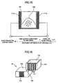
Fig. 18 , in a third example of thewaste liquid container 40 according to the first embodiment of the present invention, pluralfirst sensors 111 are provided on the entire four sidewalls of thefirst container 101 while pluralsecond sensors 112 are provided on an the entire single sidewall of thesecond container 102. With this configuration, the three-dimensional shape and the peak of thesolid waste matter 122 accumulated in thefirst container 101 can be detected. - Next, an exemplary waste
liquid container 40 is described in detail with reference toFig. 19 . Thewaste liquid container 40 includes the capacitance typefirst sensor 111 and anoptical sensor 113 acting as the second detecting part attached to a top wall of thesecond container 102. -
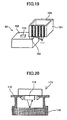
Figs. 20 and21 are schematic diagrams for describing theoptical sensor 113. Theoptical sensor 113 includes areflection type photosensor 114, an absorbingmember 116 for absorbing waste ink, and acase 115 for holding thephotosensor 114 and the absorbingmember 116. The absorbingmember 116 is a material having a characteristic of easily absorbing liquid waste ink (e.g., felt, sponge) and having a color capable of sufficiently reflecting light (e.g., white). Thephotosensor 114 is attached to thecase 115 so that a certain distance is kept from the absorbingmember 116. Thecase 115 provides a sealed space between the absorbingmember 116 and the photosensor 114 so that light or ink mist can be prevented from entering the space. By sealing the space between the absorbingmember 116 and thephotosensor 114, ink mist can be prevented from adhering to a sensor surface of thephotosensor 114. Thereby, erroneous detection by thephotosensor 114 can be prevented. Furthermore, by sealing the space, only the light reflected from the absorbingmember 116 is detected by thephotosensor 114. Thereby, thephotosensor 114 can satisfactorily determine whether waste ink is absorbed by the absorbingmember 116. - As shown in
Figs. 20 and21 , thephotosensor 114 has claw parts which pressingly engage the upper opening part of thecase 115 when thephotosensor 114 is inserted in the upper opening part of thecase 115. Thereby, thephotosensor 114 can be attached to thecase 115. The absorbingmember 116 is fixed to an absorbing member holding part of thecase 115 by using, for example, an adhesive agent. The absorbingmember 116 is attached to the top wall of thesecond container 102 in a manner that the absorbingmember 116 faces the inside of thesecond container 102 and absorbs the waste ink inside thesecond container 102. - Thereby, the
liquid waste matter 123 is absorbed by the absorbingmember 116 as its height inside thesecond container 102 increases, and the color of the absorbingmember 116 changes as theliquid waste matter 123 is absorbed. Accordingly, theoptical sensor 114 can detect whether thesecond container 102 is full. - Next, an example of a
main control part 201 of theimage forming apparatus 100 including the above-described wasteliquid container 40 is described with reference toFig. 22. Fig. 22 is a block diagram of a portion related to controls performed by themain control part 201 for detecting a fullwaste liquid container 40 and changing a waste ink discharging position. - The
main control part 201 is for performing control of the entireimage forming apparatus 100 including control for changing a waste liquid discharging position according to an embodiment of the present invention. Themain control part 201 includes, for example, a CPU, a ROM, a RAM, an I/O device, and a rewritable non-volatile memory. Themain control part 201 moves thecarriage 23 in a desired direction for a prescribed amount by rotating themain scan motor 27 via adriving circuit 202. Furthermore, themain control part 201 drives therecording head 24 for ejecting liquid droplets (e.g., ink) via adriving circuit 203. Furthermore, themain control part 201 drives the absorbingpump 45 by rotating the absorbingpump motor 47 via adriving circuit 204. - The
main control part 201 also determines whether the first andsecond containers waste liquid container 40 are in a full state or a nearly-full (almost full container) by receiving detection signals indicative of the status of the waste liquid inside thewaste liquid container 40 from the first andsecond sensors main control part 201 also determines whether thewaste liquid container 40 is mounted by receiving detection signals from atank mount sensor 119. - Next, thresholds that are set in correspondence with the
first sensor 111 of thefirst container 101 and thesecond sensor 112 of thesecond container 102 are described with reference toFig. 23 . - One or more thresholds are set with respect to the shape (capacity) of the
first container 101 of thewaste liquid container 40 beforehand. In a case where the waste liquid reaches any one of the thresholds, themain control part 201 may control (limit) usage of theimage forming apparatus 100 or change a position for discharging waste ink. For example, in order to detect the status of thefirst container 101, thresholds D, E, F, G are set in correspondence with the height (position) of thesolid waste matter 122 detected by the first sensor 111 (corresponding heights satisfying a relationship of D < E < F < G). Furthermore, in order to detect the status of thesecond container 102, thresholds B and C are set in correspondence with the height (position) of theliquid waste matter 123 detected by the second sensor 112 (corresponding heights satisfying a relationship of B < C). The settings of the thresholds are not limited to those of the above-described example. - Next, an exemplary full-container detecting operation and a waste liquid discharge position changing operation are described with reference to
Fig. 24 . - First, it is determined whether the height of the
solid waste matter 122 of thefirst container 101 detected by thefirst sensor 111 is equal to or greater than the threshold D (H1 ≧ D) (S501). In a case where the height of thesolid waste matter 122 has not reached the threshold D (No in S501), it is determined whether the height of theliquid waste matter 123 of thesecond container 102 detected by thesecond sensor 112 is equal to or greater than the threshold B (H2 ≧ B) (S506) If the height of theliquid waste matter 123 is less than the threshold B, the operation returns to the beginning. - On the other hand, in a case where the height of the
solid waste matter 122 is equal to or greater than the threshold D (Yes in S501), it is determined whether the height of thesolid waste matter 122 of thefirst container 101 detected by thefirst sensor 111 is equal to or greater than the threshold E (H1 ≧ E) (S502). In a case where the height H1 is less than the threshold E, that is, in a case where the height H1 is equal to or greater than the threshold D but less than the threshold E (D ≦ H1 < E), the position for discharging waste ink into thefirst container 101 is changed to a predetermined first discharge position (variable position α) (S601). - In a case where the height H1 is equal to or greater than the threshold E, it is determined whether the height of the
solid waste matter 122 of thefirst container 101 detected by thefirst sensor 111 is equal to or greater than the threshold F (H1 ≧ F) (S503). In a case where the height H1 is less than the threshold F, that is, in a case where the height H1 is equal to or greater than the threshold E but less than the threshold F (E ≦ H1 < F), the position for discharging waste ink into thefirst container 101 is changed to a predetermined second discharge position (variable position β) (S602). - In a case where the height H1 is equal to or greater than the threshold F, it is determined whether the height of the
solid waste matter 122 of thefirst container 101 detected by thefirst sensor 111 is less than the threshold G (H1 < G) (S504). In a case where the height H1 is less than the threshold G, that is, in a case where the height H1 is equal to or greater than the threshold F but less than the threshold G (F ≦ H1 < G), it is determined that thefirst container 101 is nearly full (nearly-full container). When thefirst container 101 is determined to be nearly full, a nearly-full container operation is performed. The nearly-full container operation includes, for example, a process for indicating that thefirst container 101 of thewaste liquid container 40 is nearly full on a display of a control panel of theimage forming apparatus 100 or reporting that thefirst container 101 of thewaste liquid container 40 is nearly full to a printer driver of a host computer. - On the other hand, in a case where the height H1 is not less than the threshold G, that is, in a case where the height H1 is equal to or greater than the threshold G, it is determined that the
first container 101 is full (full container). When thefirst container 101 is full, a full-container operation is performed. The full-container operation includes, for example, a process of shutting down (stopping) operations of theimage forming apparatus 100 along with a process for indicating that thefirst container 101 of thewaste liquid container 40 should be replaced on a display of a control panel of theimage forming apparatus 100 or reporting that thefirst container 101 of thewaste liquid container 40 should be replaced to a printer driver of a host computer. - Meanwhile, in a case where the height H2 of the
liquid waste matter 123 detected by thesecond sensor 112 is equal to or greater than the threshold B (H2 ≧ B) (Yes in S506), it is determined whether the height H2 is less than the threshold C (S507). In a case where the height H2 is less than the threshold C, that is, in a case where the height H2 is equal to or greater than the threshold B but less than the threshold C (B ≦ H2 < C), it is determined that thesecond container 102 is nearly full (nearly-full container). When thesecond container 102 is determined to be nearly full, a nearly-full container operation is performed. The nearly-full container operation includes, for example, a process for indicating that thesecond container 102 of thewaste liquid container 40 is nearly full on a display of a control panel of theimage forming apparatus 100 or reporting that thesecond container 102 of thewaste liquid container 40 is nearly full to a printer driver of a host computer. On the other hand, in a case where the height H2 is not less than the threshold C, that is, in a case where the height H2 is equal to or greater than the threshold C, it is determined that thesecond container 102 is full (full container). When thesecond container 102 is full, a full-container operation is performed. The full-container operation includes, for example, a process of shutting down (stopping) operations of theimage forming apparatus 100 along with a process for indicating that thesecond container 102 of thewaste liquid container 40 should be replaced on a display of a control panel of theimage forming apparatus 100 or reporting that thesecond container 102 of thewaste liquid container 40 should be replaced to a printer driver of a host computer. - Next, as one example of the waste liquid discharge position changing operation, a blank ejection position changing operation is described with reference to
Fig. 25 . - In a case of changing a blank ejection position according to a predetermined threshold, the
carriage 23 is controlled to stop at a suitable position. The stopping position of thecarriage 23 is controlled according to data of the waste liquid (waste ink) accumulated in thefirst container 101 of thewaste liquid container 40. For example, thecarriage 23 stops at a position where waste liquid is discharged (dropped) on an area where the height of the waste liquid is lowest. By preventing waste liquid from being discharged onto a single area in thefirst container 101, waste liquid can be prevented from accumulating in a single area of thefirst container 101. Accordingly, thefirst container 101 of thewaste liquid container 40 can be efficiently used. - As another example of the waste liquid discharge position changing operation, an operation of changing a discharge position of the discharge tube 46 (discharge tube position changing operation) is described with reference to
Fig. 26 . - In this example, a distal end of a discharging part of the
discharge tube 46 is inclined toward thefirst container 101 of thewaste liquid container 26. By changing the rotational speed of the absorbingpump motor 47 that drives the absorbingpump 45, the discharge rate of thewaste liquid 121 is changed, to thereby change the landing area (impact area) of the dischargedwaste liquid 121. By preventingwaste liquid 121 from being discharged onto a single area in thefirst container 101, waste liquid can be prevented from accumulating in a single area of thefirst container 101. Accordingly, thefirst container 101 of thewaste liquid container 40 can be efficiently used. In addition, changing of the discharge position can be achieved with a simple configuration in which thedischarge tube 46 is inclined (tilted) at a suitable angle. - Next, an exemplary waste
liquid container 40 is described in detail with reference toFig. 27. Fig. 27 is a schematic diagram showing a detachable attachment structure of thesensor electrode 111a of thefirst sensor 111 according to an embodiment of the present invention. - In this example, the
sensor electrode 111a included in thefirst sensor 111 is formed as a thin film. Thesensor electrode 111a is formed of a conductive material such as aluminum, copper, nickel, or iron. Although thesensor electrode 111a may be fixed to thefirst container 101 by using an adhesive agent or double-faced tape, it is preferable to detachably attach the sensor electrode 11a to thefirst container 101 by providingclaws 131 at the sidewall of thefirst container 101 and inserting theclaws 131 into correspondingholes 130 formed in thesensor electrode 111a. Although not shown inFig. 27 , the sensor electrode provided in thesecond sensor 112 may be configured in the same manner as thefirst sensor 111. - Since the
sensors waste liquid container 40, thewaste liquid container 40 and thesensors - Next, an exemplary
image forming apparatus 100 is described with reference toFigs. 28 and29 .Fig. 28 is a perspective view showing a detachable attachment structure of thewaste liquid container 40.Fig. 29 is a schematic diagram showing a mounting (attaching) part of thewaste liquid container 40. - The
waste liquid container 40 can be removed out from themain body 1 of theimage forming apparatus 100 by removing an outer cover part provided at the back of themain body 1. As shown inFig. 29 , atank detection sensor 119 is provided to anattachment part 120 provided inside themain body 1 for detecting the presence of thewaste liquid container 40. - As shown in
Fig. 30 , themain control part 201 determines whether thetank detection sensor 119 is "on". Thetank detection sensor 119 is "on" when thewaste liquid container 40 is detached from theattachment part 120. In a case where thewaste liquid container 40 is removed (i.e. detached from the attachment part 120), theimage forming apparatus 100 shifts to a shut-down state. - Since the waste liquid container 40 (including the
first container 101 or the second container 102) is detachable from themain body 1 of theimage forming apparatus 100, thewaste liquid container 40 can be re-attached after eliminating stored waste liquid or replaced with a new waste liquid container. This facilitates maintenance of theimage forming apparatus 100. Furthermore, since the presence of thewaste liquid container 40 can be detected, waste liquid can be prevented from being erroneously discharged in a state where thewaste liquid container 40 is not attached to theimage forming apparatus 100. Accordingly, the surrounding of thewaste liquid container 40 can be prevented from being stained by waste liquid. - Although the above-described embodiments of the present invention is described by using an exemplary configuration of a copy machine (apparatus having a copying function), the above-described embodiments of the present invention can also be applied to an apparatus having, for example, a printer function or a facsimile function.
- The present invention is not limited to the specifically disclosed embodiments, and variations and modifications may be made without departing from the scope of the present invention as claimed.
Claims (13)
- A waste liquid container for storing a waste liquid discharged from an image forming apparatus, the waste liquid container comprising:a first container (101) having a single waste liquid inlet (104) into which the waste liquid enters and including a first sensor for detecting the waste liquid inside the first container; anda second container (102) communicating (103) with the first container and including a second sensor for detecting the waste liquid inside the second container;wherein the first and the second containers are detachably attached to each other; characterised in that:the first sensor is configured to detect a height and a peak position of the waste liquid contained inside the first container and including a plurality of sensor electrodes (111) provided on the entire sidewall of the first container with respect to the height direction.
- A waste liquid container as claimed in claim 1, wherein the second container is positioned lower than the first container.
- A waste liquid container as claimed in claim 1 or 2, wherein the first sensor includes a pair of sensor electrodes provided at oppositely facing outer sidewalls of the first container, wherein the first sensor is configured to measure capacitance between the pair of sensor electrodes by applying an alternating current between the pair of sensor electrodes.
- A waste liquid container as claimed in claim 1 or 2, wherein the first sensor is configured to detect a shape and a peak position of the waste liquid in the first container by applying an alternating current between the plural sensor electrodes and measuring capacitance between the plural sensor electrodes.
- A waste liquid container in claim 1, 2, 3 or 4, wherein the first sensor is provided in a plurality of areas of the first container.
- A waste liquid container as claimed in claim 1, 2, 3, 4 or 5, wherein the second sensor (114) is configured to detect a height of the waste liquid contained in the second container.
- A waste liquid container as claimed in any one of the preceding claims, wherein the first and second containers are separately replaceable.
- An image forming apparatus comprising:an image forming part (24) for performing image formation;a discharging part (38) for discharging a waste liquid that does not contribute to image formation; anda waste liquid container according to any one of the preceding claims.
- An image forming apparatus as claimed in claim 8, further comprising:a control part for determining whether each of the first and the second containers is full according to detection results from the first and the second sensors respectively.
- An image forming apparatus as claimed in claim 9, wherein the discharging part is configured to change a position for discharging the waste liquid into the first container according to the detection result from the first sensor.
- An image forming apparatus as claimed in claim 9 or 10 further comprising another discharging part for performing blank ejection of the waste liquid,
wherein the discharging part is configured to change a position for discharging the waste liquid into the first container according to the detection result from the first sensor. - An image forming apparatus as claimed in claim 11, wherein the other discharging part is a discharging tube.
- An image forming apparatus as claimed in claim 12, wherein the discharge tube is inclined with respect to the waste liquid inlet.
Applications Claiming Priority (1)
| Application Number | Priority Date | Filing Date | Title |
|---|---|---|---|
| JP2007184044A JP5151285B2 (en) | 2007-07-13 | 2007-07-13 | Waste liquid container and image forming apparatus |
Publications (3)
| Publication Number | Publication Date |
|---|---|
| EP2014472A2 EP2014472A2 (en) | 2009-01-14 |
| EP2014472A3 EP2014472A3 (en) | 2009-07-29 |
| EP2014472B1 true EP2014472B1 (en) | 2011-09-14 |
Family
ID=39876237
Family Applications (1)
| Application Number | Title | Priority Date | Filing Date |
|---|---|---|---|
| EP08252330A Expired - Fee Related EP2014472B1 (en) | 2007-07-13 | 2008-07-08 | Waste liquid container and image forming apparatus |
Country Status (3)
| Country | Link |
|---|---|
| US (1) | US8899723B2 (en) |
| EP (1) | EP2014472B1 (en) |
| JP (1) | JP5151285B2 (en) |
Families Citing this family (15)
| Publication number | Priority date | Publication date | Assignee | Title |
|---|---|---|---|---|
| JP4985356B2 (en) * | 2007-11-29 | 2012-07-25 | ブラザー工業株式会社 | Liquid ejection device |
| US20100154706A1 (en) * | 2008-12-19 | 2010-06-24 | Canon Kabushiki Kaisha | Liquid applying apparatus |
| JP5824956B2 (en) | 2011-08-16 | 2015-12-02 | 株式会社リコー | Image forming apparatus |
| JP5929199B2 (en) | 2012-01-05 | 2016-06-01 | 株式会社リコー | Image forming apparatus |
| JP5927989B2 (en) | 2012-02-29 | 2016-06-01 | 株式会社リコー | Image forming apparatus |
| JP5948993B2 (en) * | 2012-03-14 | 2016-07-06 | セイコーエプソン株式会社 | Liquid ejector |
| KR102081249B1 (en) * | 2013-05-27 | 2020-02-26 | 삼성디스플레이 주식회사 | Monitoring apparatus and printing apparatus |
| US9555633B2 (en) | 2014-10-09 | 2017-01-31 | Ricoh Company, Ltd. | Replay unit for waste liquid container and image forming apparatus incorporating the relay unit |
| JP6707838B2 (en) * | 2015-10-30 | 2020-06-10 | ブラザー工業株式会社 | Liquid consumption device |
| JP6790423B2 (en) * | 2016-03-31 | 2020-11-25 | ブラザー工業株式会社 | Inkjet recording device |
| JP6852317B2 (en) | 2016-09-09 | 2021-03-31 | ブラザー工業株式会社 | Liquid recovery device and liquid consumption device equipped with this |
| JP6425701B2 (en) * | 2016-10-31 | 2018-11-21 | キヤノン株式会社 | Ink jet recording device |
| JP7139825B2 (en) * | 2018-09-21 | 2022-09-21 | 株式会社リコー | Device for receiving blank ejection, ejecting liquid, printing device |
| JP7280677B2 (en) * | 2018-09-27 | 2023-05-24 | 株式会社日立産機システム | Inkjet recording device |
| JP2022026973A (en) | 2020-07-31 | 2022-02-10 | 株式会社リコー | Liquid discharge device and liquid discharge method |
Family Cites Families (19)
| Publication number | Priority date | Publication date | Assignee | Title |
|---|---|---|---|---|
| JPH08197749A (en) * | 1995-01-31 | 1996-08-06 | Matsushita Electric Ind Co Ltd | Ink jet printer |
| JPH08267781A (en) * | 1995-03-31 | 1996-10-15 | Canon Inc | Ink jet recording device |
| JPH08290581A (en) * | 1995-04-25 | 1996-11-05 | Matsushita Graphic Commun Syst Inc | Ink supplying device and recorder using the same |
| US6312094B1 (en) * | 1997-07-30 | 2001-11-06 | Toshiba Tec Kabushiki Kaisha | Ink-jet printer |
| JP2000085143A (en) | 1998-09-10 | 2000-03-28 | Copyer Co Ltd | Waste ink collecting apparatus |
| JP2000141704A (en) | 1998-11-06 | 2000-05-23 | Fine Technol Kk | Waste ink recovering mechanism for ink jet printer |
| JP2001310487A (en) * | 2000-04-28 | 2001-11-06 | Ricoh Co Ltd | Apparatus for sustaining function of recording head and ink jet recorder comprising it |
| JP4614589B2 (en) * | 2001-07-04 | 2011-01-19 | 株式会社リコー | Inkjet recording device |
| JP2004130701A (en) * | 2002-10-11 | 2004-04-30 | Riso Kagaku Corp | Inkjet recorder and method of controlling the same |
| JP2004136550A (en) | 2002-10-17 | 2004-05-13 | Seiko Epson Corp | Ink jet recorder |
| JP4570865B2 (en) | 2003-12-15 | 2010-10-27 | 株式会社リコー | Head cleaning device and image forming apparatus |
| JP2005247476A (en) | 2004-03-03 | 2005-09-15 | Ricoh Co Ltd | Image formation device |
| JP2006007640A (en) * | 2004-06-28 | 2006-01-12 | Seiko Epson Corp | Printer, method of printing, and printing system |
| JP2006137079A (en) * | 2004-11-12 | 2006-06-01 | Ricoh Co Ltd | Waste liquid storage vessel and image forming apparatus |
| JP3933660B2 (en) | 2004-12-03 | 2007-06-20 | 株式会社リコー | Image forming apparatus |
| JP2006281508A (en) * | 2005-03-31 | 2006-10-19 | Canon Inc | Inkjet recording apparatus |
| JP2007076308A (en) * | 2005-09-16 | 2007-03-29 | Seiko Epson Corp | Waste liquid discharge device and liquid jet device |
| JP2007125812A (en) * | 2005-11-04 | 2007-05-24 | Canon Inc | Inkjet recorder and recovering method therefor |
| JP2007160871A (en) * | 2005-12-16 | 2007-06-28 | Canon Inc | Inkjet recording device |
-
2007
- 2007-07-13 JP JP2007184044A patent/JP5151285B2/en not_active Expired - Fee Related
-
2008
- 2008-07-08 EP EP08252330A patent/EP2014472B1/en not_active Expired - Fee Related
- 2008-07-09 US US12/170,147 patent/US8899723B2/en not_active Expired - Fee Related
Also Published As
| Publication number | Publication date |
|---|---|
| JP2009018529A (en) | 2009-01-29 |
| US8899723B2 (en) | 2014-12-02 |
| JP5151285B2 (en) | 2013-02-27 |
| EP2014472A2 (en) | 2009-01-14 |
| US20090015632A1 (en) | 2009-01-15 |
| EP2014472A3 (en) | 2009-07-29 |
Similar Documents
| Publication | Publication Date | Title |
|---|---|---|
| EP2014472B1 (en) | Waste liquid container and image forming apparatus | |
| KR100879145B1 (en) | Image forming apparatus | |
| EP0767067B1 (en) | Printer with detachable printhead | |
| US20090021548A1 (en) | Inkjet printing apparatus and method for performing maintenance on inkjet printing apparatus | |
| KR100781731B1 (en) | Image forming apparatus | |
| US8770689B2 (en) | Image forming apparatus including recording head for ejecting droplets | |
| US8894169B2 (en) | Image forming apparatus including recording head for ejecting liquid droplets | |
| EP2651648B1 (en) | Image forming apparatus | |
| US8777370B2 (en) | Image forming apparatus | |
| US8454122B2 (en) | Image forming apparatus | |
| US6296354B1 (en) | Ink container with plural ink chambers emptied sequentially, and recording apparatus having the same | |
| US8628168B2 (en) | Image forming apparatus and image forming method | |
| JP2010000671A (en) | Ink cartridge and image forming device | |
| JP4841217B2 (en) | Image forming apparatus | |
| US8727494B2 (en) | Droplet ejection device and image forming apparatus | |
| JP4919651B2 (en) | Image forming apparatus | |
| JP2008302501A (en) | Waste liquid storage vessel and image forming apparatus | |
| JP4860516B2 (en) | Waste liquid container and image forming apparatus | |
| JP2009101609A (en) | Image forming apparatus | |
| JP4993574B2 (en) | Image forming device, replacement waste liquid tank, waste liquid tank | |
| JP3248544B2 (en) | Ink jet recording device | |
| JP2006137079A (en) | Waste liquid storage vessel and image forming apparatus | |
| JP2006150872A (en) | Waste liquid storage container and image forming device | |
| JP2008221525A (en) | Liquid jetting device, image recording device, and method for controlling image recording device | |
| JP2005246697A (en) | Image forming apparatus |
Legal Events
| Date | Code | Title | Description |
|---|---|---|---|
| PUAI | Public reference made under article 153(3) epc to a published international application that has entered the european phase |
Free format text: ORIGINAL CODE: 0009012 |
|
| 17P | Request for examination filed |
Effective date: 20080708 |
|
| AK | Designated contracting states |
Kind code of ref document: A2 Designated state(s): AT BE BG CH CY CZ DE DK EE ES FI FR GB GR HR HU IE IS IT LI LT LU LV MC MT NL NO PL PT RO SE SI SK TR |
|
| AX | Request for extension of the european patent |
Extension state: AL BA MK RS |
|
| PUAL | Search report despatched |
Free format text: ORIGINAL CODE: 0009013 |
|
| AK | Designated contracting states |
Kind code of ref document: A3 Designated state(s): AT BE BG CH CY CZ DE DK EE ES FI FR GB GR HR HU IE IS IT LI LT LU LV MC MT NL NO PL PT RO SE SI SK TR |
|
| AX | Request for extension of the european patent |
Extension state: AL BA MK RS |
|
| AKX | Designation fees paid |
Designated state(s): DE ES FR GB IT |
|
| 17Q | First examination report despatched |
Effective date: 20100531 |
|
| GRAP | Despatch of communication of intention to grant a patent |
Free format text: ORIGINAL CODE: EPIDOSNIGR1 |
|
| GRAS | Grant fee paid |
Free format text: ORIGINAL CODE: EPIDOSNIGR3 |
|
| GRAA | (expected) grant |
Free format text: ORIGINAL CODE: 0009210 |
|
| AK | Designated contracting states |
Kind code of ref document: B1 Designated state(s): DE ES FR GB IT |
|
| REG | Reference to a national code |
Ref country code: GB Ref legal event code: FG4D |
|
| REG | Reference to a national code |
Ref country code: DE Ref legal event code: R096 Ref document number: 602008009760 Country of ref document: DE Effective date: 20111110 |
|
| PG25 | Lapsed in a contracting state [announced via postgrant information from national office to epo] |
Ref country code: IT Free format text: LAPSE BECAUSE OF FAILURE TO SUBMIT A TRANSLATION OF THE DESCRIPTION OR TO PAY THE FEE WITHIN THE PRESCRIBED TIME-LIMIT Effective date: 20110914 |
|
| PLBE | No opposition filed within time limit |
Free format text: ORIGINAL CODE: 0009261 |
|
| STAA | Information on the status of an ep patent application or granted ep patent |
Free format text: STATUS: NO OPPOSITION FILED WITHIN TIME LIMIT |
|
| 26N | No opposition filed |
Effective date: 20120615 |
|
| REG | Reference to a national code |
Ref country code: DE Ref legal event code: R097 Ref document number: 602008009760 Country of ref document: DE Effective date: 20120615 |
|
| PG25 | Lapsed in a contracting state [announced via postgrant information from national office to epo] |
Ref country code: ES Free format text: LAPSE BECAUSE OF FAILURE TO SUBMIT A TRANSLATION OF THE DESCRIPTION OR TO PAY THE FEE WITHIN THE PRESCRIBED TIME-LIMIT Effective date: 20111225 |
|
| REG | Reference to a national code |
Ref country code: FR Ref legal event code: PLFP Year of fee payment: 9 |
|
| PGFP | Annual fee paid to national office [announced via postgrant information from national office to epo] |
Ref country code: DE Payment date: 20160722 Year of fee payment: 9 Ref country code: GB Payment date: 20160721 Year of fee payment: 9 |
|
| PGFP | Annual fee paid to national office [announced via postgrant information from national office to epo] |
Ref country code: FR Payment date: 20160721 Year of fee payment: 9 |
|
| REG | Reference to a national code |
Ref country code: DE Ref legal event code: R119 Ref document number: 602008009760 Country of ref document: DE |
|
| GBPC | Gb: european patent ceased through non-payment of renewal fee |
Effective date: 20170708 |
|
| REG | Reference to a national code |
Ref country code: FR Ref legal event code: ST Effective date: 20180330 |
|
| PG25 | Lapsed in a contracting state [announced via postgrant information from national office to epo] |
Ref country code: DE Free format text: LAPSE BECAUSE OF NON-PAYMENT OF DUE FEES Effective date: 20180201 Ref country code: GB Free format text: LAPSE BECAUSE OF NON-PAYMENT OF DUE FEES Effective date: 20170708 |
|
| PG25 | Lapsed in a contracting state [announced via postgrant information from national office to epo] |
Ref country code: FR Free format text: LAPSE BECAUSE OF NON-PAYMENT OF DUE FEES Effective date: 20170731 |