EP2013985B1 - Vorrichtung und verfahren zum wechseln zwischen einbenutzer- und mehrbenutzer-mimo-betrieb in einem drahtlosen netzwerk - Google Patents
Vorrichtung und verfahren zum wechseln zwischen einbenutzer- und mehrbenutzer-mimo-betrieb in einem drahtlosen netzwerk Download PDFInfo
- Publication number
- EP2013985B1 EP2013985B1 EP07746246.3A EP07746246A EP2013985B1 EP 2013985 B1 EP2013985 B1 EP 2013985B1 EP 07746246 A EP07746246 A EP 07746246A EP 2013985 B1 EP2013985 B1 EP 2013985B1
- Authority
- EP
- European Patent Office
- Prior art keywords
- base station
- subscriber station
- subpacket
- data
- pilot
- Prior art date
- Legal status (The legal status is an assumption and is not a legal conclusion. Google has not performed a legal analysis and makes no representation as to the accuracy of the status listed.)
- Active
Links
Images


Classifications
-
- H—ELECTRICITY
- H04—ELECTRIC COMMUNICATION TECHNIQUE
- H04L—TRANSMISSION OF DIGITAL INFORMATION, e.g. TELEGRAPHIC COMMUNICATION
- H04L1/00—Arrangements for detecting or preventing errors in the information received
- H04L1/12—Arrangements for detecting or preventing errors in the information received by using return channel
- H04L1/16—Arrangements for detecting or preventing errors in the information received by using return channel in which the return channel carries supervisory signals, e.g. repetition request signals
- H04L1/1607—Details of the supervisory signal
- H04L1/1657—Implicit acknowledgement of correct or incorrect reception, e.g. with a moving window
-
- H—ELECTRICITY
- H04—ELECTRIC COMMUNICATION TECHNIQUE
- H04B—TRANSMISSION
- H04B7/00—Radio transmission systems, i.e. using radiation field
- H04B7/02—Diversity systems; Multi-antenna system, i.e. transmission or reception using multiple antennas
- H04B7/04—Diversity systems; Multi-antenna system, i.e. transmission or reception using multiple antennas using two or more spaced independent antennas
- H04B7/0413—MIMO systems
- H04B7/0417—Feedback systems
-
- H—ELECTRICITY
- H04—ELECTRIC COMMUNICATION TECHNIQUE
- H04B—TRANSMISSION
- H04B7/00—Radio transmission systems, i.e. using radiation field
- H04B7/02—Diversity systems; Multi-antenna system, i.e. transmission or reception using multiple antennas
- H04B7/04—Diversity systems; Multi-antenna system, i.e. transmission or reception using multiple antennas using two or more spaced independent antennas
- H04B7/0413—MIMO systems
- H04B7/0452—Multi-user MIMO systems
-
- H—ELECTRICITY
- H04—ELECTRIC COMMUNICATION TECHNIQUE
- H04B—TRANSMISSION
- H04B7/00—Radio transmission systems, i.e. using radiation field
- H04B7/02—Diversity systems; Multi-antenna system, i.e. transmission or reception using multiple antennas
- H04B7/04—Diversity systems; Multi-antenna system, i.e. transmission or reception using multiple antennas using two or more spaced independent antennas
- H04B7/06—Diversity systems; Multi-antenna system, i.e. transmission or reception using multiple antennas using two or more spaced independent antennas at the transmitting station
- H04B7/0613—Diversity systems; Multi-antenna system, i.e. transmission or reception using multiple antennas using two or more spaced independent antennas at the transmitting station using simultaneous transmission
- H04B7/0615—Diversity systems; Multi-antenna system, i.e. transmission or reception using multiple antennas using two or more spaced independent antennas at the transmitting station using simultaneous transmission of weighted versions of same signal
- H04B7/0619—Diversity systems; Multi-antenna system, i.e. transmission or reception using multiple antennas using two or more spaced independent antennas at the transmitting station using simultaneous transmission of weighted versions of same signal using feedback from receiving side
- H04B7/0621—Feedback content
- H04B7/0632—Channel quality parameters, e.g. channel quality indicator [CQI]
-
- H—ELECTRICITY
- H04—ELECTRIC COMMUNICATION TECHNIQUE
- H04L—TRANSMISSION OF DIGITAL INFORMATION, e.g. TELEGRAPHIC COMMUNICATION
- H04L1/00—Arrangements for detecting or preventing errors in the information received
- H04L1/0001—Systems modifying transmission characteristics according to link quality, e.g. power backoff
- H04L1/0015—Systems modifying transmission characteristics according to link quality, e.g. power backoff characterised by the adaptation strategy
-
- H—ELECTRICITY
- H04—ELECTRIC COMMUNICATION TECHNIQUE
- H04L—TRANSMISSION OF DIGITAL INFORMATION, e.g. TELEGRAPHIC COMMUNICATION
- H04L1/00—Arrangements for detecting or preventing errors in the information received
- H04L1/0001—Systems modifying transmission characteristics according to link quality, e.g. power backoff
- H04L1/0023—Systems modifying transmission characteristics according to link quality, e.g. power backoff characterised by the signalling
- H04L1/0028—Formatting
-
- H—ELECTRICITY
- H04—ELECTRIC COMMUNICATION TECHNIQUE
- H04L—TRANSMISSION OF DIGITAL INFORMATION, e.g. TELEGRAPHIC COMMUNICATION
- H04L1/00—Arrangements for detecting or preventing errors in the information received
- H04L1/02—Arrangements for detecting or preventing errors in the information received by diversity reception
- H04L1/06—Arrangements for detecting or preventing errors in the information received by diversity reception using space diversity
-
- H—ELECTRICITY
- H04—ELECTRIC COMMUNICATION TECHNIQUE
- H04L—TRANSMISSION OF DIGITAL INFORMATION, e.g. TELEGRAPHIC COMMUNICATION
- H04L1/00—Arrangements for detecting or preventing errors in the information received
- H04L1/12—Arrangements for detecting or preventing errors in the information received by using return channel
- H04L1/16—Arrangements for detecting or preventing errors in the information received by using return channel in which the return channel carries supervisory signals, e.g. repetition request signals
- H04L1/18—Automatic repetition systems, e.g. Van Duuren systems
- H04L1/1829—Arrangements specially adapted for the receiver end
- H04L1/1835—Buffer management
-
- H—ELECTRICITY
- H04—ELECTRIC COMMUNICATION TECHNIQUE
- H04L—TRANSMISSION OF DIGITAL INFORMATION, e.g. TELEGRAPHIC COMMUNICATION
- H04L1/00—Arrangements for detecting or preventing errors in the information received
- H04L1/12—Arrangements for detecting or preventing errors in the information received by using return channel
- H04L1/16—Arrangements for detecting or preventing errors in the information received by using return channel in which the return channel carries supervisory signals, e.g. repetition request signals
- H04L1/18—Automatic repetition systems, e.g. Van Duuren systems
- H04L1/1867—Arrangements specially adapted for the transmitter end
- H04L1/1887—Scheduling and prioritising arrangements
-
- H—ELECTRICITY
- H04—ELECTRIC COMMUNICATION TECHNIQUE
- H04B—TRANSMISSION
- H04B7/00—Radio transmission systems, i.e. using radiation field
- H04B7/02—Diversity systems; Multi-antenna system, i.e. transmission or reception using multiple antennas
- H04B7/04—Diversity systems; Multi-antenna system, i.e. transmission or reception using multiple antennas using two or more spaced independent antennas
- H04B7/06—Diversity systems; Multi-antenna system, i.e. transmission or reception using multiple antennas using two or more spaced independent antennas at the transmitting station
- H04B7/0686—Hybrid systems, i.e. switching and simultaneous transmission
- H04B7/0689—Hybrid systems, i.e. switching and simultaneous transmission using different transmission schemes, at least one of them being a diversity transmission scheme
-
- H—ELECTRICITY
- H04—ELECTRIC COMMUNICATION TECHNIQUE
- H04L—TRANSMISSION OF DIGITAL INFORMATION, e.g. TELEGRAPHIC COMMUNICATION
- H04L1/00—Arrangements for detecting or preventing errors in the information received
- H04L1/0001—Systems modifying transmission characteristics according to link quality, e.g. power backoff
- H04L1/0002—Systems modifying transmission characteristics according to link quality, e.g. power backoff by adapting the transmission rate
- H04L1/0003—Systems modifying transmission characteristics according to link quality, e.g. power backoff by adapting the transmission rate by switching between different modulation schemes
-
- H—ELECTRICITY
- H04—ELECTRIC COMMUNICATION TECHNIQUE
- H04L—TRANSMISSION OF DIGITAL INFORMATION, e.g. TELEGRAPHIC COMMUNICATION
- H04L1/00—Arrangements for detecting or preventing errors in the information received
- H04L1/0001—Systems modifying transmission characteristics according to link quality, e.g. power backoff
- H04L1/0009—Systems modifying transmission characteristics according to link quality, e.g. power backoff by adapting the channel coding
-
- H—ELECTRICITY
- H04—ELECTRIC COMMUNICATION TECHNIQUE
- H04L—TRANSMISSION OF DIGITAL INFORMATION, e.g. TELEGRAPHIC COMMUNICATION
- H04L1/00—Arrangements for detecting or preventing errors in the information received
- H04L1/0001—Systems modifying transmission characteristics according to link quality, e.g. power backoff
- H04L1/0023—Systems modifying transmission characteristics according to link quality, e.g. power backoff characterised by the signalling
- H04L1/0026—Transmission of channel quality indication
-
- H—ELECTRICITY
- H04—ELECTRIC COMMUNICATION TECHNIQUE
- H04L—TRANSMISSION OF DIGITAL INFORMATION, e.g. TELEGRAPHIC COMMUNICATION
- H04L1/00—Arrangements for detecting or preventing errors in the information received
- H04L1/12—Arrangements for detecting or preventing errors in the information received by using return channel
- H04L1/16—Arrangements for detecting or preventing errors in the information received by using return channel in which the return channel carries supervisory signals, e.g. repetition request signals
- H04L1/18—Automatic repetition systems, e.g. Van Duuren systems
- H04L1/1812—Hybrid protocols; Hybrid automatic repeat request [HARQ]
-
- H—ELECTRICITY
- H04—ELECTRIC COMMUNICATION TECHNIQUE
- H04W—WIRELESS COMMUNICATION NETWORKS
- H04W28/00—Network traffic management; Network resource management
- H04W28/16—Central resource management; Negotiation of resources or communication parameters, e.g. negotiating bandwidth or QoS [Quality of Service]
- H04W28/18—Negotiating wireless communication parameters
Definitions
- the present application relates generally to wireless communications and, more specifically, to an apparatus for dynamically switching between single-user and multi-user MIMO operation in a wireless network.
- MIMO communications are well-known techniques for improving the capacity and reliability of a wireless communication channel.
- a conventional 4x4 MIMO system transmits four different data streams separately from four transmit antennas of a base station. The four transmitted signals are received at the four receive antennas of a subscriber station.
- the subscriber station then performs some form of spatial signal processing on the received signals in order to recover the four data streams.
- the subscriber station or user device
- V-BLAST spatial signal processing technique
- Other variants of MIMO techniques may include some type of space-time coding across the transmit antennas (e.g., D-BLAST) or may include a beamforming technique, such as spatial division multiple access (SDMA).
- SDMA spatial division multiple access
- the base station adds a cyclic redundancy check (CRC) block to a single data block and then performs coding and modulation on the combined CRC and data blocks.
- the coded and modulated symbols are then demultiplexed for transmission over multiple antennas.
- the base station demultiplexes a data block into smaller data blocks and attaches individual CRC blocks to the smaller data blocks.
- the base station then performs separate coding and modulation operations on the smaller combined CRC and data.
- the smaller data and CRC blocks are then transmitted via separate MIMO antennas or beams.
- multi-code word transmission allows for more efficient post-decoding interference cancellation, because a CRC check can be performed on each of the code words before the code word is cancelled from the overall signal. In this way, only correctly received code words are cancelled, thereby avoiding any interference propagation in the cancellation process.
- Hybrid acknowledge request is a retransmission technique whereby the transmitter sends redundant coded information (e.g., parity bits in turbo coding) in small increments (or subpackets).
- the subpackets are generated at the transmitter by first performing channel coding on the information packet and then breaking the resulting coded bit stream into smaller units called subpackets. For example, an original data packet P and the corresponding parity bits may be broken into subpackets SP1, SP2, SP3, ..., SPn.
- the receiver tries to decode the information and recover the original data packet P after receiving the first subpacket SP1. In case of unsuccessful decoding, the receiver stores the SP1 and sends a NACK message to the transmitter.
- the transmitter After receiving the NACK message, the transmitter transmits the second subpacket SP2. After receiving the second subpacket, the receiver combines subpacket SP2 with the previously stored subpacket SP1 and jointly decodes subpackets SP1 and SP2 in order to recover original data packet P. At any point, if the information packet is successfully decoded (e.g., by a successful cyclic redundancy check (CRC) operation), the receiver sends an ACK message to the transmitter. After receiving an ACK message, the transmitter moves on to the transmission of a new information packet to the same or a different subscriber station (or user).
- CRC cyclic redundancy check
- CQI channel quality indicator
- a multi-user MIMO system requires that a large number of subscriber stations are present in the system, so that each subscriber station can be selected for transmission when it experiences the best channel quality. If the number of subscriber stations in the system is small, the system is less likely to find subscriber stations experiencing peak channel conditions. This degrades the performance of a multi-user MIMO scheme. In the presence of a small number of subscriber station, it is advantageous to schedule multiple MIMO streams to the same subscriber station using single-user MIMO transmission mode. The number of subscriber stations with traffic buffers that are not empty varies dynamically due to packet data traffic burst characteristics. It should be noted that, for single-user MIMO mode, multiple CQI feedback values are required, while in multi-user MIMO mode, a single CQI feedback value per subscriber station may suffice.
- a MIMO system operates either in single user (or single subscriber station) MIMO mode or in multi-user (multi-subscriber station) MIMO mode.
- System performance is better for the single-user MIMO case when the number of subscriber stations in the system is small.
- a multi-user MIMO system gives better performance in the presence of large number of subscriber stations.
- the number of subscriber stations having data to receive or to transmit in a system may vary dynamically due to the bursty nature of the traffic. Subscriber stations are not aware of the dynamic traffic situation in the base station and, therefore, cannot switch the mode of CQI feedback between single-user and multi-user CQI feedback. As a result, conventional MIMO schemes result in inefficient use of system capacity and resources.
- US 2004/136349 A1 refers to a MIMO system with multiple spatial multiplexing modes.
- a MIMO system supports multiple spatial multiplexing modes for improved performance and greater flexibility.
- These modes may include a single-user steered mode that transmits multiple data streams on orthogonal spatial channels to a single receiver, a single-user non-steered mode that transmits multiple data streams from multiple antennas to a single receiver without spatial processing at a transmitter, a multi-user steered mode that transmits multiple data streams simultaneously to multiple receivers with spatial processing at a transmitter, and a multi-user non-steered mode that transmits multiple data streams from multiple antennas (co-located or non co-located) without spatial processing at the transmitter(s) to receiver(s) having multiple antennas.
- a spatial multiplexing mode is selected for the user terminal set from among the multiple spatial multiplexing modes supported by the system.
- US 2002/177447 A1 refers to a method and apparatus for allocating uplink resources in a multiple-input multiple-output, MIMO, communication system.
- a number of sets of terminals is formed for possible data transmission, with each set including a unique combination of terminals and corresponds to a hypothesis to be evaluated. The performance of each hypothesis is evaluated and one of the evaluated hypotheses is selected based on the performance.
- the terminals in the selected hypothesis are scheduled for data transmission.
- a successive cancellation receiver processing scheme may be used to process the signals transmitted by the scheduled terminals.
- one or more orderings of the terminals in each set may be formed, with each terminal ordering corresponding to a sub-hypothesis to be evaluated. The performance of each sub-hypothesis is then evaluated and one of the sub-hypotheses is selected.
- a base station for use in a wireless network.
- the disclosed base station transmits in a downlink to a plurality of subscriber stations using a plurality of antennas according to a multiple input, multiple-output (MIMO) protocol.
- MIMO multiple input, multiple-output
- the base station during a first downlink subframe operates in single-user MIMO mode in which the base station transmits a first data subpacket to a first subscriber station using a first antenna and transmits a second data subpacket to the first subscriber station using a second antenna.
- the base station operates in multi-user MIMO mode in which the base station transmits a third data subpacket to the first subscriber station using the first antenna and transmits a fourth data subpacket to a second subscriber station using the second antenna.
- the first data subpacket is generated from a first original data packet and the second data subpacket is generated from a second original data packet different than the first original data packet.
- the third data subpacket is also generated from one of the first and second original data packets.
- a subscriber station capable of communicating with a base station of a wireless network, wherein the base station is capable of transmitting in a downlink using a plurality of antennas according to a multiple input, multiple-output (MIMO) protocol.
- MIMO multiple input, multiple-output
- the disclosed subscriber station receives a first data subpacket transmitted from a first antenna of the base station and receives a second data subpacket transmitted from a second antenna of the base station.
- the subscriber station receives a third data subpacket transmitted from the first antenna of the base station.
- FIGURES 1 through 11 discussed below, and the various embodiments used to describe the principles of the present disclosure in this patent document are by way of illustration only and should not be construed in any way to limit the scope of the disclosure. Those skilled in the art will understand that the principles of the present disclosure may be implemented in any suitably arranged wireless network.
- the present disclosure provides dynamic switching between single-user MIMO mode and multi-user MIMO mode.
- single-user MIMO mode multiple streams are transmitted to a single user (or subscriber station)
- multi-user MIMO mode multiple streams are transmitted to multiple users (subscriber stations).
- a subscriber station always reports a single CQI feedback value on the assumption that multi-user MIMO mode is in operation.
- the base station uses the best stream CQI feedback value reported by the subscriber station to select modulation and coding schemes for all the MIMO streams directed to that subscriber station. As this CQI value only applies to one stream, hybrid ARQ operation is used for recovery of the remaining streams.
- the subscriber station may try to decode the other streams nonetheless. If the subscriber station successfully decodes one or more other streams, the subscriber station may cancel the successfully decoded streams from the overall received signal to reduce the interference from the overall received signal. After interference cancellation, the subscriber station may again attempt to decode the streams that previously failed.
- the present disclosure is implemented in a wireless network in which multi-antenna base stations transmit to subscriber stations (i.e., user devices) according to an orthogonal frequency division multiplexing (OFDM) or orthogonal frequency division multiple access (OFDMA) protocol.
- the base station uses multiple-input, multiple-output (MIMO) antennas to implement spatial division multiplexing techniques.
- MIMO multiple-input, multiple-output
- the disclosed base station may transmit to the same subscriber station from multiple antennas using different subcarriers on each antenna, depending on the fading of the subcarriers from each antenna.
- the implementation of the present disclosure in an OFDMA network should not be construed so as to limit the scope of the present disclosure.
- the present disclosure may be implemented in, for example, a GSM network, a CDMA2000 network, or the like.
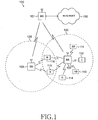
- FIGURE 1 illustrates exemplary orthogonal frequency division multiple access (OFDMA) wireless network 100, which dynamically switches between single-user and multi-user MIMO operation according to the principles of the present disclosure.
- wireless network 100 includes base station (BS) 101, base station (BS) 102, base station (BS) 103, and other similar base stations (not shown).
- Base station 101 is in communication with base station 102 and base station 103.
- Base station 101 is also in communication with Internet 130 or a similar IP-based network (not shown).
- Base station 102 provides wireless broadband access (via base station 101) to Internet 130 to a first plurality of subscriber stations within coverage area 120 of base station 102.
- the first plurality of subscriber stations includes subscriber station 111, which may be located in a small business (SB), subscriber station 112, which may be located in an enterprise (E), subscriber station 113, which may be located in a WiFi hotspot (HS), subscriber station 114, which may be located in a first residence (R), subscriber station 115, which may be located in a second residence (R), and subscriber station 116, which may be a mobile device (M), such as a cell phone, a wireless laptop, a wireless PDA, or the like.
- SB small business
- E enterprise
- HS WiFi hotspot
- R first residence
- subscriber station 116 which may be a mobile device (M), such as a cell phone, a wireless laptop, a wireless PDA, or
- Base station 103 provides wireless broadband access (via base station 101) to Internet 130 to a second plurality of subscriber stations within coverage area 125 of base station 103.
- the second plurality of subscriber stations includes subscriber station 115 and subscriber station 116.
- base stations 101-103 may communicate with each other and with subscriber stations 111-116 using OFDM or OFDMA techniques.
- Base station 101 may be in communication with either a greater number or a lesser number of base stations. Furthermore, while only six subscriber stations are depicted in FIGURE 1 , it is understood that wireless network 100 may provide wireless broadband access to additional subscriber stations. It is noted that subscriber station 115 and subscriber station 116 are located on the edges of both coverage area 120 and coverage area 125. Subscriber station 115 and subscriber station 116 each communicate with both base station 102 and base station 103 and may be said to be operating in handoff mode, as known to those of skill in the art.
- Subscriber stations 111-116 may access voice, data, video, video conferencing, and/or other broadband services via Internet 130.
- one or more of subscriber stations 111-116 may be associated with an access point (AP) of a WiFi WLAN.
- Subscriber station 116 may be any of a number of mobile devices, including a wireless-enabled laptop computer, personal data assistant, notebook, handheld device, or other wireless-enabled device.
- Subscriber stations 114 and 115 may be, for example, a wireless-enabled personal computer (PC), a laptop computer, a gateway, or another device.
- each one of base stations 101-103 uses multiple antennas to transmit data to each subscriber station in the downlink and to receive data from each subscriber stations in the uplink.
- each one of base stations 101-103 is capable of transmitting data to a selected subscriber station using one group of subcarriers (or subband) on a first antenna and a different group of subcarriers (or subband) on a second antenna.
- BS 102 may transmit downlink data to SS 116 from a first antenna (ANTI) using a first group of 64 subcarriers (i.e., Subband 1) and may simultaneously transmit downlink data to SS 116 from a second antenna (ANT2) using a second group of 64 subcarriers (i.e., Subband2).
- BS 102 may transmit downlink data to SS 115 from antenna ANT1 using Subband2 and may simultaneously transmit downlink data to SS 115 from antenna ANT2 using Subband1. Since the fading at the receiver from each antenna is independent of the other antennas, the allocation of subbands at each antenna is independent of the allocations of subbands at other antennas. Thus, the allocations of subbands are done on an antenna-by-antenna basis.
- FIGURE 2A is a high-level diagram of an orthogonal frequency division multiple access (OFDMA) transmit path.
- FIGURE 2B is a high-level diagram of an orthogonal frequency division multiple access (OFDMA) receive path.
- the OFDMA transmit path is implemented in base station (BS) 102 and the OFDMA receive path is implemented in subscriber station (SS) 116 for the purposes of illustration and explanation only.
- BS base station
- SS subscriber station
- a similar (though not identical) OFDMA receive path may also be implemented in BS 102 and a similar (though not identical) OFDMA transmit path may be implemented in SS 116.
- FIGURE 2A illustrates two transmit paths that may send data in multi-user mode to, for example, two subscriber stations (e.g., SS 116 and SS 115) via two transmit antennas, ANT1 and ANT2 (not shown), or that may send data in single-user mode to one subscriber station (e.g., SS 116) via two transmit antennas, ANT1 and ANT2.
- two subscriber stations e.g., SS 116 and SS 115
- ANT1 and ANT2 not shown
- ANT1 and ANT2 not shown
- a base station may use N transmit antennas to transmit data to M subscriber stations using selective allocation of different groups of subcarriers to different transmit antennas.
- the base station also may employ some form of precoding on the data streams before mapping of the data symbols to physical antennas, thus creating a set of beams or virtual antennas.
- the principles of the present disclosure in this case apply equally to the beams or virtual antennas as if they are physical antennas.
- a first transmit path is directed to antenna ANT1 (not shown) and a second transmit path is directed to antenna ANT2 (not shown).
- the first transmit path comprises add cyclic redundancy check (CRC) block 201a, channel coding and modulation block 205a, serial-to-parallel (S-to-P) block 210, IFFT block 215a, parallel-to-serial (P-to-S) block 220a, add cyclic prefix (CP) block 225a, and up-converter (UC) block 230a.
- CRC cyclic redundancy check
- S-to-P serial-to-parallel
- IFFT IFFT block 215a
- P-to-S parallel-to-serial
- CP cyclic prefix
- UC up-converter
- the second transmit path comprises add cyclic redundancy check (CRC) block 201b, channel coding and modulation block 205b, serial-to-parallel (S-to-P) block 210, IFFT block 215b, parallel-to-serial (P-to-S) block 220b, add cyclic prefix (CP) block 225b, up-converter (UC) block 230b.
- CRC cyclic redundancy check
- S-to-P serial-to-parallel
- P-to-S parallel-to-serial
- CP cyclic prefix
- UC up-converter
- Base station 102 further comprises main controller 240, which may be, for example, a microprocessor or a microcontroller.
- Main controller 240 controls the overall operation of BS 102, including switching BS 102 between single-user mode and multi-user mode according to the principles of the present disclosure.
- the receive path in subscriber station (SS) 116 (or 115) comprises down-converter (DC) 255, remove cyclic prefix block 260, serial-to-parallel (S-to-P) block 265, Size N Fast Fourier Transform (FFT) block 270, parallel-to-serial (P-to-S) block 275, channel decoding and demodulation block 280, and main controller 285.
- DC down-converter
- FFT Fast Fourier Transform
- P-to-S parallel-to-serial
- channel decoding and demodulation block 280 and main controller 285.
- Main controller 285 controls the overall operation of SS 116, including switching SS 116 between operating in a single-user network environment and operating in a multi-user network environment according to the principles of the present disclosure.
- FIGURES 2A and 2B may be implemented in software while other components may be implemented by configurable hardware or a mixture of software and configurable hardware.
- the FFT blocks and the IFFT blocks described in this disclosure document may be implemented as configurable software algorithms executed by a processor, where the value of Size N may be modified according to the implementation.
- add CRC block 201a receives a first block of data, Stream 1 Data, which may be transmitted to, for example, SS 116 via antennas ANT1 and ANT2 in single user mode, or to SS 116 or SS 115, or both, via antennas ANT1 and ANT2 in multi-user mode.
- Add CRC block 201a performs a cyclic redundancy check operation that adds a CRC value to the Stream 1 Data block.
- Channel coding and modulation block 205a receives input bits from add CRC block 201a and applies coding (e.g., turbo coding) and modulates (e.g., BPSK, QPSK, QAM, etc.) the input bits to produce a sequence of frequency-domain modulation symbols.
- Serial-to-parallel block 210 converts (i.e., de-multiplexes) the serial modulated symbols to parallel data to produce N parallel symbol streams where N is the IFFT/FFT size used in BS 102, SS 116, and SS 115.
- Size N IFFT block 215a performs an IFFT operation on the N parallel symbol streams to produce time-domain output signals.
- Parallel-to-serial block 220a converts (i.e., multiplexes) the parallel time-domain output symbols from Size N IFFT block 215a to produce a serial time-domain signal.
- Add cyclic prefix block 225a then inserts a cyclic prefix to the time-domain signal.
- up-converter 230a modulates (i.e., up-converts) the output of add cyclic prefix block 225a to RF frequency for transmission via antenna ANT1.
- Add CRC block 201b receives a first block of data, Stream2 Data, which may be transmitted to, for example, SS 116 via antennas ANT1 and ANT2 in single user mode, or to SS 116 or SS 115, or both, via antennas ANT1 and ANT2 in multi-user mode.
- Add CRC block 201b performs a cyclic redundancy check operation that adds a CRC value to the Stream2 Data block.
- Channel coding and modulation block 205b receives input bits from add CRC block 201b and applies coding (e.g., turbo coding) and modulates (e.g., BPSK, QPSK, QAM, etc.) the input bits to produce a sequence of frequency-domain modulation symbols.
- Serial-to-parallel block 210 converts (i.e., de-multiplexes) the serial modulated symbols to parallel data to produce N parallel symbol streams where N is the IFFT/FFT size used in BS 102, SS 116, and SS 115.
- Size N IFFT block 215b performs an IFFT operation on the N parallel symbol streams to produce time-domain output signals.
- Parallel-to-serial block 220b converts (i.e., multiplexes) the parallel time-domain output symbols from Size N IFFT block 215b to produce a serial time-domain signal.
- Add cyclic prefix block 225b then inserts a cyclic prefix to the time-domain signal.
- up-converter 230b modulates (i.e., up-converts) the output of add cyclic prefix block 225b to RF frequency for transmission via antenna ANT2.
- the transmitted RF signals from antennas ANT1 and ANT2 arrive at SS 116 after passing through the wireless channel and reverse operations to those at BS 102 are performed.
- Down-converter 255 down-converts the received signal to baseband frequency and remove cyclic prefix block 260 removes the cyclic prefix to produce the serial time-domain baseband signal.
- Serial-to-parallel block 265 converts the time-domain baseband signal to parallel time domain signals.
- Size N FFT block 270 then performs an FFT algorithm to produce N parallel frequency-domain signals.
- Parallel-to-serial block 275 converts the parallel frequency-domain signals to a sequence of modulated data symbols.
- Channel decoding and demodulation block 280 demodulates and then decodes the modulated symbols to recover the original input data stream.
- the transmit path and receive path components described herein and illustrated in FIGURES 2A and 2B are configurable devices that may be re-programmed and controlled by main controller 240 in BS 102 or main controller 285 in SS 116.
- main controller 240 is operable to configure modulation block 205 to adapt to different modulation techniques (e.g., BPSK, QPSK, QAM, etc.).
- main controller 285 is operable to similarly configure demodulation block 280.
- Main controllers 240 and 285 are also operable to modify the value of Size N.
- Main controllers 240 and 285 are operable to allocate uplink channel resources to subscriber stations 111-116 as described in U.S. Patent Application Serial No. 11/390,056 .
- each one of base stations 101-103 is capable of dynamically allocating uplink channel resources to subscriber stations 111-116 according to the number of subscriber stations that will be receiving downlink data transmissions and will be required therefore to send ACK or NACK messages (and associated pilot signals) back to a transmitting base station.
- the uplink channel resources may be independently and selectively allocated for each transmission, rather than being permanently dedicated to particular subscriber stations.
- FIGURE 3 illustrates the allocation of subcarriers in wireless network 100 according to one embodiment of the present disclosure.
- a total of 512 OFDM subcarriers (or tones) are divided into 8 groups (or subbands) of 64 contiguous subcarriers (SCs) each.
- the first subband, SB1 contains subcarriers SC1-SC64
- the second subband, SB2 contains subcarriers SC65-SC128, and so forth.
- the eighth (last) subband, SB8 contains subcarriers SC449-SC512.
- a given subscriber station may be allocated one or more of these subbands.
- a MIMO spatial multiplexing antenna array using OFDMA allocates the same subband on each transmit antenna to the same subscriber station.
- SS 116 is allocated subband SB1 on antenna ANT1
- SS 116 must also be allocated subband SB1 on antenna ANT2.
- the eight subbands, SB1-SB8, are allocated according to channel fading at the receiver for the case of two transmit antennas, ANT1 and ANT2, and two subscriber stations, SS 115 and SS 116.
- the received signals at SS 116 and SS 115 from each of the two transmit antennas experience frequency-selective fading due to multipath effects.
- the channel qualities from each of transmit antennas ATN1 and ANT2 at SS 115 and SS 116 are independent.
- the channel from base station (BS) 102 to each of SS 115 and SS 116 is also independent due to the different locations of SS 115 and SS 116 within a cell. Therefore, SS 115 or SS 116 experience independent fading from each of the two transmit antennas as shown in FIGURE 3 .
- Curve 330a represents a flat fading characteristic at antenna ANT1.
- Dotted-line curve 310a represents the frequency selective fading of the downlink signal from antenna ANT1 seen by the receiver of SS 116.
- Solid-line curve 320a represents the frequency selective fading of the downlink signal from antenna ANT1 seen by the receiver of SS 115.
- Curve 330b represents a flat fading characteristic at antenna ANT2.
- Dotted-line curve 310b represents the frequency selective fading of the downlink signal from antenna ANT2 seen by the receiver of SS 116.
- Solid-line curve 320b represents the frequency selective fading of the downlink signal from antenna ANT2 seen by the receiver of SS 115.
- a subscriber station is scheduled for transmission on a given subband on a given antenna if its channel quality on that particular subband for a particular antenna is better than all the other subscriber stations in the cell. It is also possible to take other QoS criteria into account when selecting subscriber stations for transmission.
- SS 116 is in a relative up-fade on antenna ANT1 compared to SS 115 on subbands SB1, SB2, SB6, SB7 and SB8.
- SS 115 is in a relative up-fade on antenna ANT1 compared to SS 116 on subbands SB3, SB4 and SB5.
- the relative fading at antenna ANT1 is used to determine subband allocation 350 for antenna ANT1 near the bottom of FIGURE 3 .
- SS 116 is in a relative up-fade on antenna ANT2 compared to SS 115 on subbands SB3, SB6, SB7 and SB8.
- SS 115 is in a relative up-fade on antenna ANT2 compared to SS 116 on subbands SB1, SB2, SB4 and SB5.
- the relative fading at antenna ANT2 is used to determine subband allocation 360 for antenna ANT2 near the bottom of FIGURE 3 .
- FIGURE 4 illustrates an alternate allocation of subcarriers in wireless network 100 according to one embodiment of the present disclosure.
- a given subscriber station has the best channel fading characteristics in a given subband on both transmit antennas, then only one transmit antenna is used to transmit to that subscriber station on that subband. On the other antenna, that subband is left empty.
- SS 116 had the best fading characteristics on both ANT1 and ANT2 in subbands SB6, SB7 and SB8. It is further noted that SS 115 had the best fading characteristics on both ANT1 and ANT2 in subbands SB4 and SB5.
- subband SB8 is left empty in subband allocation 450 for antenna ANT1 near the bottom of FIGURE 4 , and SS 116 receives in subband SB8 only from antenna ANT2.
- subbands SB4, SB5, and SB6 are left empty in subband allocation 460 for antenna ANT2 near the bottom of FIGURE 4 , and SS 116 receives in subbands SB6 and SB7 only from antenna ANT1 and SS 115 receives in subbands SB4 and SB5 only from antenna ANT1.
- the present disclosure provides a mechanism for dynamic switching between single-user and multi-user MIMO, whereby a user always reports a single CQI assuming multi-user MIMO operation.
- the base station uses the best stream CQI reported by the subscriber station to schedule the subscriber station and select modulation and coding schemes for all the MIMO streams. As this CQI value only applies to one stream, hybrid ARQ operation is used to recover the remaining streams.
- the subscriber station tries to decode other streams. If the subscriber station decodes one or more other streams, the subscriber station cancels the successfully decoded streams to reduce the interference in the overall received signal and then decodes again the streams that previously failed.
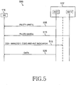
- FIGURE 5 depicts message flow diagram 500, which illustrates CQI feedback and scheduling in wireless network 100 according to one embodiment of the present disclosure.
- base station (BS) 102 transmits a first pilot signal, Pilot1, from antenna ANT1 (process step 505) and transmits a second pilot signal, Pilot2, from antenna ANT2 (process step 510).
- Subscriber station (SS) 116 receives the Pilot1 signal and calculates a first channel quality indicator value, CQI1, from the measured Pilot1 signal using, for example, a linear minimum mean square error (LMMSE) operation.
- SS 116 also receives the Pilot2 signal and calculates a second channel quality indicator value, CQI2, from the measured Pilot2 signal using, for example, a linear minimum mean square error (LMMSE) operation.
- LMMSE linear minimum mean square error
- SS 116 transmits to BS 102 the best CQI value and an antenna indicator value (ANT) that identifies which of the two antennas, ANT1 or ANT2, is associated with the best CQI value (process step 515).
- BS 102 may then schedule a downlink Data transmission for SS 116 on the identified (or selected) antenna using a modulation and coding scheme (MCS) that corresponds to the reported best CQI value (process step 520).
- MCS modulation and coding scheme
- the ANT indicator value indicated that antenna ANT1 was associated with the best reported CQI value.
- BS 102 transmits a Data block from antenna ANT1 to SS 102 using a modulation and coding scheme corresponding to the CQI1 value.
- another user e.g., SS 115
- SS 115 another user that reports a better CQI on the other antenna may be selected for transmission using the same resource (i.e., time-frequency slot) on the other antenna.
- FIGURE 6 depicts message flow diagram 600, which illustrates CQI feedback and scheduling in wireless network 100 according to another embodiment of the present disclosure.
- base station (BS) 102 transmits a first pilot signal, Pilot1, from antenna ANT1 (process step 605) and transmits a second pilot signal, Pilot2, from antenna ANT2 (process step 610).
- Subscriber station (SS) 116 receives the Pilot1 signal and calculates a first channel quality indicator value, CQI1, from the measured Pilot1 signal using, for example, a linear minimum mean square error (LMMSE) operation.
- SS 116 also receives the Pilot2 signal and calculates a second channel quality indicator value, CQI2, from the measured Pilot2 signal using, for example, a linear minimum mean square error (LMMSE) operation.
- LMMSE linear minimum mean square error
- SS 116 transmits to BS 102 the best CQI value and an antenna indicator value (ANT) that identifies which of the two antennas, ANT1 or ANT2, is associated with the best CQI value (process step 615).
- ANT antenna indicator value
- BS 102 may then schedule a downlink data transmission for SS 116 in a single-user MIMO mode, with signals transmitted to SS 116 from both the ANT1 antenna and the ANT2 antenna.
- BS 102 selects the same modulation and coding scheme (MCS) on both antennas (ANT1 and ANT2) based on the single CQI feedback value from process step 615.
- MCS modulation and coding scheme
- the selected modulation and coding scheme applies to the best antenna stream at that time, but is nonetheless used for both antennas.
- BS 102 transmits Data1 stream from antenna ANT1 (process step 620) using the MCS corresponding to antenna ANT2 and transmits Data2 stream from antenna ANT2 (process step 625) using the same MCS corresponding to antenna ANT2.
- SS 116 may cancel the first decoded stream in a single-user MIMO scenario which can actually improve the SINR for the stream that is decoded second.
- the second stream may be decodable even when the first stream fails. In that event, the second stream may be cancelled and the receiver (e.g., SS 116) may try to decode the stream that failed on the first attempt.
- FIGURE 7 depicts message flow diagram 700, which illustrates interference cancellation and a hybrid acknowledge request (ARQ) protocol for two multiple-input, multiple-output (MIMO) streams in wireless network 100 according to another embodiment of the present disclosure.
- ARQ hybrid acknowledge request
- MIMO multiple-input, multiple-output
- FIGURE 7 two downlink transmissions, Stream1 and Stream2, are transmitted to the same user (e.g., SS 116).
- SS 116 may perform, for example, an LMMSE operation to suppress the inter-stream interference.
- SS 116 tries to decode Stream1 (process step 705). If the Stream1 decoding is successful (Yes in process step 710), SS 116 cancels decoded Stream1 from the overall received signal (process step 715) and then tries to decode Stream2 (process step 720). If the Stream2 decoding is unsuccessful (No in process step 725), SS 116 sends BS 102 an ACK message for Stream1 and a NACK message for Stream2 (process step 730). If the Stream2 decoding is successful (Yes in process step 725), SS 116 sends BS 102 an ACK message for Stream1 and an ACK message for Stream2 (process step 735).
- SS 116 tries to decode Stream2 (process step 740). If the Stream2 decoding is unsuccessful (No in process step 745), SS 116 sends BS 102 a NACK message for Stream1 and a NACK message for Stream2 (process step 750). If the Stream2 decoding is successful (Yes in process step 745), SS 116 cancels decoded Stream2 from the overall received signal (process step 755) and then tries to decode Stream1 again (process step 760).
- SS 116 sends BS 102 a NACK message for Stream1 and an ACK message for Stream2 (process step 770). If the Stream1 decoding is successful (Yes in process step 765), SS 116 sends BS 102 an ACK message for Stream1 and an ACK message for Stream2 (process step 735).
- BS 102 transmits additional redundancy information using Hybrid ARQ protocol for both the streams. In case a NACK message for only one stream, BS 102 transmits the redundant information only for the failed stream.
- FIGURE 8 depicts message flow diagram 800, which illustrates interference cancellation and a hybrid ARQ protocol for two MIMO streams according to another embodiment of the present disclosure.
- FIGURE 8 is substantially identical to FIGURE 7 , except that a single ACK/NACK message is sent in process steps 830, 835, 850 and 870 as a result of the decoding attempt for both the streams. This is different than process steps 730, 735, 750 and 770, which use multiple ACK/NACK messages.
- an ACK signal is sent when both streams are successful (process step 835) and a NACK signal is sent when either one stream or both streams fail (process steps 830, 850 and 870).
- This approach reduces ACK/NACK feedback signaling overhead.
- BS 102 transmits redundant information using the hybrid ARQ protocol for both streams.
- BS 102 moves on to new packet transmissions to the same subscriber station or a different subscriber station.
- FIGURE 9 depicts message flow diagram 900, which illustrates single-user multi-code word MIMO hybrid ARQ operation according to another embodiment of the present disclosure.
- three data packets, A1, A2 and A3, are to be transmitted to SS 116, while two other data packets, B1 and B2, are to be transmitted to another subscriber station (e.g., SS 115).
- SS 115 subscriber station
- sixteen downlink subframes (SF1-SF16) are shown for each of two antennas (ANT1 and ANT 2).
- Antenna ANT1 transmits Stream1 and antenna ANT2 transmits Stream2.
- BS 102 transmits data subpacket A11 from data packet A1 to SS 116 in Stream1 and transmits data subpacket A21 from data packet A2 in Stream2.
- SS 116 successfully decodes original data packet A1 from data subpacket A11, but fails to decode original data packet A2 from subpacket A21.
- SS 116 transmits a hybrid ARQ acknowledgement message, ACK(1,0), back to BS 102.
- BS 102 transmits new data subpacket A31 from new data packet A3 to SS 116 in Stream2. Since data packet A2 was not successfully decoded in subframe SF1, BS 102 transmits in Stream1 a second data subpacket A22 associated with original data packet A2. Alternatively, BS 102 could transmit subpacket A22 on Stream2, while the new transmission of subpacket A31 occurs in Stream 1.
- SS 116 attempts to decode original data packet A2 by combining data subpackets A21 and A22 and attempts to decode original data packet A3 from subpacket A31.
- FIGURE 9 it is assumed that SS 116 again fails to decode original data packet A2 and also fails to decode original data packet A3.
- SS 116 transmits the hybrid ARQ message, ACK(0,0), to BS 102.
- BS 102 transmits new data subpacket B11 from new data packet B1 to SS 115 in Stream1 and transmits new data subpacket B21 from data packet B2 in Stream2.
- SS 115 successfully decodes original data packet B1 from data subpacket B11 and successfully decodes original data packet B2 from subpacket B21.
- SS 115 transmits a hybrid ARQ acknowledgement message, ACK(1,1), back to BS 102.
- BS 102 resumes Hybrid ARQ transmission to SS 116 of packets A2 and A3.
- BS 102 transmits to SS 116 data subpacket A32 from data packet A3 in Stream1 and transmits data subpacket A23 from data packet A2 in Stream2.
- SS 116 attempts to decode original data packet A2 by combining data subpackets A21, A22, and A23 and attempts to decode original data packet A3 by combining data subpackets A31 and A32.
- SS 116 transmits a hybrid ARQ acknowledgement message, ACK(1,1), back to BS 102.
- FIGURE 10 depicts message flow diagram 1000, which illustrates multi-user, multi-code word, MIMO hybrid ARQ operation according to another embodiment of the present disclosure.
- data subpackets may be sent to different subscriber stations on different MIMO streams.
- a receiving subscriber station provides hybrid ARQ feedback only for the data stream it receives.
- base station 102 attempts to transmit to SS 116 original data packets A1 and A2 and attempts to transmit to SS 115 original data packets B1 and B2.
- BS 102 transmits a first data subpacket A11 from original data packet A1 to SS 116 in Stream 1 and transmits a first data subpacket B11 from original data packet B1 to SS 115 in Stream2.
- SS 116 successfully decodes original data packet A1 from data subpacket A11, but fails to decode original data packet B1 from subpacket B11.
- SS 116 transmits an ACK message to BS 102 and SS 115 transmits a NACK message to BS 102.
- BS 102 transmits a first data subpacket A21 from original data packet A2 to SS 116 in Stream2 and transmits a second data subpacket B12 from original data packet B1 to SS 115 in Stream1.
- SS 116 fails to decode original data packet A2 from data subpacket A21 and fails to decode original data packet B1 from the combined subpackets B11 and B12.
- SS 116 transmits a NACK message to BS 102 and SS 115 also transmits a NACK message to BS 102.
- BS 102 transmits a second data subpacket A22 from original data packet A2 to SS 116 in Stream1 and transmits a third data subpacket B13 from original data packet B1 to SS 115 in Stream2.
- SS 116 fails to decode original data packet A2 from combined data subpackets A21 and A22, but successfully decodes original data packet B1 from the combined subpackets B11, B12 and B13.
- SS 116 transmits a NACK message to BS 102 and SS 115 transmits an ACK message to BS 102.
- BS 102 transmits a third data subpacket A23 from original data packet A2 to SS 116 in Stream1 and transmits a first data subpacket B21 from original data packet B2 to SS 115 in Stream2.
- SS 116 successfully decodes original data packet A2 from combined data subpackets A21, A22 and A23 and successfully decodes original data packet B2 from data subpacket B21.
- SS 116 transmits an ACK message to BS 102 and SS 115 transmits an ACK message to BS 102.
- FIGURE 11 depicts message flow diagram 1100, which illustrates switching between single-user, multi-code word, MIMO hybrid ARQ operation and multi-user, multi-code word, MIMO hybrid ARQ operation according to the principles of the present disclosure.
- base station 102 attempts to transmit to SS 116 original data packets A1 and A2 and attempts to transmit to SS 115 original data packets B1 and B2.
- BS 102 In the first subframe (SF1), BS 102 operates in multi-user MIMO mode and transmits to SS 116 in Stream1 and to SS 115 in Stream2. In the fifth subframe (SF5), BS 102 switches to single-user MIMO mode and transmits to SS 115 only using both Stream1 and Stream2. In the ninth subframe (SF9), BS 102 switches back to multi-user MIMO mode and transmits to SS 116 in Stream2 and to SS 115 in Stream1. In the thirteenth subframe (SF13), BS 102 again switches to single-user MIMO mode and transmits to SS 116 only using both Stream1 and Stream2.
- BS 102 transmits a first data subpacket A11 from original data packet A1 to SS 116 in Stream1 and transmits a first data subpacket B11 from original data packet B1 to SS 115 in Stream2.
- SS 116 fails to decode original data packet A1 from data subpacket A11 and SS 115 fails to decode original data packet B1 from subpacket B11.
- SS 116 transmits a NACK message to BS 102 and SS 115 transmits a NACK message to BS 102.
- BS 102 transmits a second data subpacket B12 from original data packet B1 to SS 115 in Stream1 and transmits a first data subpacket B21 from original data packet B2 to SS 115 in Stream2.
- SS 115 successfully decodes original data packet B1 from combined data subpackets B11 and B12, but fails to decode original data packet B2 from data subpacket B21.
- BS 102 transmits a second data subpacket A12 from original data packet A1 to SS 116 in Stream2 and transmits a second data subpacket B22 from original data packet B2 to SS 115 in Stream 1.
- SS 116 fails to decode original data packet A1 from combined data subpacket A11 and A12 and SS 115 successfully decodes original data packet B2 from combined data subpackets B21 and B22.
- SS 116 transmits a NACK message to BS 102 and SS 115 transmits an ACK message to BS 102.
- BS 102 transmits a third data subpacket A13 from original data packet A1 to SS 116 in Stream1 and transmits a first data subpacket A21 from original data packet A2 to SS 116 in Stream2.
- SS 116 successfully decodes original data packet A1 from combined data subpackets A11, A12 and A13 and successfully decodes original data packet A2 from data subpacket A21.
- the hybrid ARQ process for a pending packet continues from the point where it is preempted. For example, transmission of packet A1 (subpacket A12) to SS 116 is preempted in subframe SF5 and resumes in subframe SF9 after BS 102 serves SS 115 on both streams in subframe SF5.
- BS 102 base station
- ANT1 and ANT2 two antennas
- SS 116 and SS 115 subscriber stations
- MIMO multiple-input, multiple-output
Landscapes
- Engineering & Computer Science (AREA)
- Computer Networks & Wireless Communication (AREA)
- Signal Processing (AREA)
- Quality & Reliability (AREA)
- Mobile Radio Communication Systems (AREA)
Claims (15)
- Basisstation zum Senden in einem drahtlosen Netzwerk in einer Abwärtsstrecke bzw. einem Downlink an eine Vielzahl von Teilnehmerstationen (111, ..., 116) mittels einer Vielzahl von Piloten entsprechend einem Mehrfach-Eingabe, Mehrfach-Ausgabe (Multiple Input Multiple Output - MIMO) Protokoll,
wobei die Basisstation (101, 102, 103) zum Betrieb während eines ersten Downlink-Subframe in einem Einbenutzer-MIMO-Modus zum Senden eines ersten Datenteilpakets an eine erste Teilnehmerstation mittels eines ersten Piloten und Senden eines zweiten Datenteilpakets an die erste Teilnehmerstation mittels eines zweiten Piloten angeordnet ist und
wobei die Basisstation (101, 102, 103) des Weiteren zum Betrieb während eines zweiten Downlink-Subframe, das dem ersten Downlink-Subframe folgt, in einem Mehrbenutzer-MIMO-Modus zum Senden eines dritten Datenteilpakets an die erste Teilnehmerstation mittels des ersten Piloten und zum Senden eines vierten Datenteilpakets an eine zweite Teilnehmerstation mittels des zweiten Piloten angeordnet ist. - Basisstation nach Anspruch 1, die eine Einrichtung zum Erzeugen des ersten Datenteilpakets aus einem ersten originalen Datenpaket und des zweiten Datenteilpakets aus einem zweiten originalen Datenpaket umfasst, das sich vom ersten originalen Datenpaket unterscheidet, und wobei das dritte Datenteilpaket aus dem ersten oder dem zweiten originalen Datenpaket erzeugt wird.
- Basisstation nach Anspruch 1, wobei die Basisstation angepasst ist, um im Anschluss an den ersten Downlink-Subframe von der ersten Teilnehmerstation ein erstes Bestätigungssignal und ein zweites Bestätigungssignal zu empfangen, das anzeigt, ob das erste Datenteilpaket und das zweite Datenteilpaket ordnungsgemäß empfangen wurden.
- Basisstation nach Anspruch 3, wobei die Basisstation des Weiteren angepasst ist, um im Anschluss an den zweiten Downlink-Subframe von der ersten Teilnehmerstation ein drittes Bestätigungssignal zu empfangen, das anzeigt, ob das dritte Datenteilpaket ordnungsgemäß empfangen wurde, und von der zweiten Teilnehmerstation ein viertes Bestätigungssignal zu empfangen, das anzeigt, ob das vierte Datenteilpaket ordnungsgemäß empfangen wurde.
- Basisstation nach Anspruch 1, die des Weiteren eine Einrichtung zum Betrieb während eines dritten Downlink-Subframe, das dem zweiten Downlink-Subframe folgt, im Einbenutzer-MIMO-Modus zum Senden durch jede der Basisstationen eines fünften Datenteilpakets an die erste Teilnehmerstation mittels des ersten Piloten und zum Senden eines sechsten Datenteilpakets an die erste Teilnehmerstation mittels des zweiten Piloten umfasst.
- Basisstation nach Anspruch 5, die des Weiteren eine Einrichtung zum Erzeugen des ersten Datenteilpakets aus einem ersten originalen Datenpaket und zum Erzeugen des zweiten Datenteilpakets aus einem zweiten originalen Datenpaket, das sich vom ersten originalen Datenpaket unterscheidet, und zum Erzeugen des dritten Datenteilpakets aus einem ersten oder zweiten Datenteilpaket und zum Erzeugen des fünften Datenteilpakets aus einem ersten oder zweiten Datenteilpaket umfasst.
- Basisstation nach Anspruch 1, wobei die Basisstation angepasst ist, um ein Modulations- und Kodierschema zum Senden von den ersten und zweiten Piloten an die erste Teilnehmerstation während des Einbenutzer-MIMO-Modus auf der Basis eines Qualitätsindikatorwertes für den ersten Kanal CQI1, der dem ersten Piloten zugeordnet ist, und eines zweiten Qualitätsindikatorwertes für den zweiten Kanal CQI2 auszuwählen, der dem zweiten Piloten zugeordnet ist, wobei das ausgewählte Modulations-und Kodierschema dem besseren des CQI1 Wertes und des CQI2 Wertes entspricht.
- Verfahren zum Betreiben einer Vielzahl von Basisstationen (101, 102, 103) in einem drahtlosen Netzwerk, wobei die Vielzahl von Basisstationen fähig ist, um mit Teilnehmerstationen in einem Abdeckungsbereich des drahtlosen Netzwerks zu kommunizieren, das umfasst:Senden durch jede der Basisstationen (101, 102, 103) in einem Downlink an eine Vielzahl von Teilnehmerstationen (111, ..., 116) mittels einer Vielzahl von Piloten entsprechend einem Mehrfach-Eingabe, Mehrfach-Ausgabe MIMO Protokoll,Betreiben von jeder der Basisstationen (101, 102, 103) während eines ersten Downlink-Subframe in einem Einbenutzer-MIMO-Modus, wobei jede der Basisstationen ein erstes Datenteilpaket an eine erste Teilnehmerstation mittels eines ersten Piloten sendet und ein zweites Datenteilpaket an die erste Teilnehmerstation mittels eines zweiten Piloten sendet, undBetreiben von jeder der Basisstationen während eines zweiten Downlink-Subframe, das dem ersten Downlink-Subframe in einem Mehrbenutzer-MIMO-Modus folgt, wobei jede der Basisstationen ein drittes Datenteilpaket an die erste Teilnehmerstation mittels des ersten Piloten sendet und ein viertes Datenteilpaket an eine zweite Teilnehmerstation mittels des zweiten Piloten sendet.
- Verfahren nach Anspruch 8, das angepasst ist, um eine Vielzahl von Basisstationen entsprechend den Ansprüchen 1 bis 7 zu betreiben.
- Teilnehmerstation, die fähig ist, um mit einer Basisstation (101, 102, 103) eines drahtlosen Netzwerks zu kommunizieren, wobei die Basisstation fähig ist, um in einem Downlink mittels einer Vielzahl von Piloten entsprechend einem Mehrfach-Eingabe, Mehrfach-Ausgabe MIMO Protokoll zu senden,
wobei die Teilnehmerstation angeordnet ist, um während eines ersten Downlink-Subframe, in dem die Basisstation im Einbenutzer-MIMO-Modus arbeitet, ein erstes Datenteilpaket zu empfangen, das von einem ersten Piloten der Basisstation (101, 102, 103) gesendet wird, und ein zweites Datenteilpaket zu empfangen, das von einem zweiten Piloten der Basisstation (101, 102, 103) gesendet wird; und
wobei die Teilnehmerstation des Weiteren angeordnet ist, um während eines zweiten Downlink-Subframe, das dem ersten Downlink-Subframe folgt, in dem die Basisstation im Mehrbenutzer-MIMO-Modus arbeitet, ein drittes Datenteilpaket zu empfangen, das von dem ersten Piloten der Basisstation (101, 102, 103) gesendet wird. - Teilnehmerstation nach Anspruch 10, wobei das erste Datenteilpaket aus einem ersten originalen Datenpaket erzeugt wird und das zweite Datenteilpaket aus einem zweiten originalen Datenpaket erzeugt wird, das sich vom ersten originalen Datenpaket unterscheidet, und wobei das dritte Datenteilpaket aus dem ersten oder dem zweiten originalen Datenpaket erzeugt wird.
- Teilnehmerstation nach Anspruch 10, die eine Einrichtung zum Senden im Anschluss an den ersten Downlink-Subframe an die Basisstation eines ersten Bestätigungssignals und eines zweiten Bestätigungssignals umfasst, das anzeigt, ob das erste Datenteilpaket und das zweite Datenteilpaket ordnungsgemäß empfangen wurden.
- Teilnehmerstation nach Anspruch 12, die eine Einrichtung zum Senden im Anschluss an den ersten Downlink-Subframe an die Basisstation eines dritten Bestätigungssignals umfasst, das anzeigt, ob das dritte Datenteilpaket ordnungsgemäß empfangen wurde.
- Teilnehmerstation nach Anspruch 10, die eine Einrichtung zum Empfangen eines ersten Eingangssignals vom ersten Piloten und zum Bestimmen eines Qualitätsindikatorwertes für den ersten Kanal CQI1, der dem ersten Piloten zugeordnet ist, und zum Bestimmen eines Qualitätsindikatorwertes für den zweiten Kanal CQI2 umfasst, der dem zweiten Piloten zugeordnet ist.
- Teilnehmerstation nach Anspruch 14, die des Weiteren eine Einrichtung zum Bestimmen eines besseren des CQI1 Wertes und des CQI2 Wertes und zum Senden an die Basisstation des besseren des CQI1 Wertes und des CQI2 Wertes und eines Pilotindikatorwertes umfasst, der dem besseren des CQI1 Wertes und des CQI2 Wertes zugeordnet ist, wobei die Basisstation angepasst ist, um ein Modulations- und Kodierschema zum Senden von den ersten und zweiten Piloten an die Teilnehmerstation während des Einbenutzer-MIMO-Modus auf der Basis des besseren des CQI1 Wertes und des CQI2 Wertes auszuwählen.
Priority Applications (1)
| Application Number | Priority Date | Filing Date | Title |
|---|---|---|---|
| EP13195972.8A EP2706672B1 (de) | 2006-04-28 | 2007-04-27 | Datenübertragung mit ACK/NACK-Rückkopplung |
Applications Claiming Priority (3)
| Application Number | Priority Date | Filing Date | Title |
|---|---|---|---|
| US79574706P | 2006-04-28 | 2006-04-28 | |
| US11/738,074 US8331342B2 (en) | 2006-04-28 | 2007-04-20 | Apparatus and method for switching between single user and multi-user MIMO operation in a wireless network |
| PCT/KR2007/002089 WO2007126265A1 (en) | 2006-04-28 | 2007-04-27 | Apparatus and method for switching between single user and multi-user mimo operation in a wireless network |
Related Child Applications (2)
| Application Number | Title | Priority Date | Filing Date |
|---|---|---|---|
| EP13195972.8A Division-Into EP2706672B1 (de) | 2006-04-28 | 2007-04-27 | Datenübertragung mit ACK/NACK-Rückkopplung |
| EP13195972.8A Division EP2706672B1 (de) | 2006-04-28 | 2007-04-27 | Datenübertragung mit ACK/NACK-Rückkopplung |
Publications (3)
| Publication Number | Publication Date |
|---|---|
| EP2013985A1 EP2013985A1 (de) | 2009-01-14 |
| EP2013985A4 EP2013985A4 (de) | 2013-08-07 |
| EP2013985B1 true EP2013985B1 (de) | 2018-01-10 |
Family
ID=38648958
Family Applications (2)
| Application Number | Title | Priority Date | Filing Date |
|---|---|---|---|
| EP07746246.3A Active EP2013985B1 (de) | 2006-04-28 | 2007-04-27 | Vorrichtung und verfahren zum wechseln zwischen einbenutzer- und mehrbenutzer-mimo-betrieb in einem drahtlosen netzwerk |
| EP13195972.8A Active EP2706672B1 (de) | 2006-04-28 | 2007-04-27 | Datenübertragung mit ACK/NACK-Rückkopplung |
Family Applications After (1)
| Application Number | Title | Priority Date | Filing Date |
|---|---|---|---|
| EP13195972.8A Active EP2706672B1 (de) | 2006-04-28 | 2007-04-27 | Datenübertragung mit ACK/NACK-Rückkopplung |
Country Status (3)
| Country | Link |
|---|---|
| US (2) | US8331342B2 (de) |
| EP (2) | EP2013985B1 (de) |
| WO (1) | WO2007126265A1 (de) |
Families Citing this family (28)
| Publication number | Priority date | Publication date | Assignee | Title |
|---|---|---|---|---|
| US8724740B2 (en) * | 2005-03-11 | 2014-05-13 | Qualcomm Incorporated | Systems and methods for reducing uplink resources to provide channel performance feedback for adjustment of downlink MIMO channel data rates |
| US8995547B2 (en) * | 2005-03-11 | 2015-03-31 | Qualcomm Incorporated | Systems and methods for reducing uplink resources to provide channel performance feedback for adjustment of downlink MIMO channel data rates |
| KR100735373B1 (ko) * | 2006-02-06 | 2007-07-04 | 삼성전자주식회사 | 통신 시스템에서 데이터 전송 방법 및 시스템 |
| BRPI0714275A2 (pt) * | 2006-08-07 | 2013-04-16 | Interdigital Tech Corp | mÉtodo, aparelho e sistema de implementaÇço de méltiplas entradas e méltiplas saÍdas virtual de méltiplos usuÁrios. |
| RU2417527C2 (ru) * | 2006-09-06 | 2011-04-27 | Квэлкомм Инкорпорейтед | Перестановка кодовых слов и уменьшенная обратная связь для сгруппированных антенн |
| TR201907743T4 (tr) | 2006-10-31 | 2019-06-21 | Ericsson Telefon Ab L M | Telekomünikasyon sistemi ve böyle bir sistemde hata kontrolü. |
| KR20130093668A (ko) * | 2006-10-31 | 2013-08-22 | 인터디지탈 테크날러지 코포레이션 | 노드 b로의 피드백 정보 제공 |
| US7796987B2 (en) * | 2007-02-14 | 2010-09-14 | Research In Motion Limited | Apparatus, and associated method, for synchronizing a mobile station with a radio network |
| KR101352042B1 (ko) * | 2007-10-15 | 2014-01-15 | 삼성전자주식회사 | 다중 입출력 무선통신 시스템에서 다중 사용자 모드를 위한채널 정보 산출 장치 및 방법 |
| CN101431801B (zh) * | 2007-11-06 | 2011-05-11 | 中兴通讯股份有限公司 | 一种接收设备控制信息的传输方法 |
| US8194602B2 (en) * | 2008-03-19 | 2012-06-05 | Futurewei Technologies, Inc. | System and method for downlink control signal structure for multi-user MIMO |
| CN101674226B (zh) * | 2008-09-12 | 2012-07-04 | 华为技术有限公司 | 一种传输方式的选择方法、装置和系统 |
| US8731087B2 (en) * | 2009-06-30 | 2014-05-20 | Microsoft Corporation | Uplink MIMO transmission from mobile communications devices |
| US8311055B2 (en) * | 2009-12-08 | 2012-11-13 | Futurewei Technologies, Inc. | System and method for scheduling users on a wireless network |
| US9031599B2 (en) * | 2009-12-08 | 2015-05-12 | Futurewei Technologies, Inc. | System and method for power control |
| US8705340B2 (en) * | 2009-12-23 | 2014-04-22 | Intel Corporation | Packet-loss handling for downlink multi-user multiple-input and multiple-output wireless network |
| US8515474B2 (en) * | 2010-01-20 | 2013-08-20 | Futurewei Technologies, Inc. | System and method for scheduling users on a wireless network |
| KR101533793B1 (ko) * | 2010-09-28 | 2015-07-09 | 한국전자통신연구원 | 다중안테나 시스템에서 안테나 선택방법 및 장치 |
| SG191116A1 (en) * | 2010-12-22 | 2013-07-31 | Nokia Siemens Networks Oy | Allocation of resources |
| US9750030B2 (en) * | 2011-08-03 | 2017-08-29 | Qualcomm Incorporated | Enhanced downlink rate adaptation for LTE heterogeneous network base stations |
| US9917629B2 (en) | 2011-12-14 | 2018-03-13 | Qualcomm Incoroporated | Multi-hypothesis channel quality indicator feedback |
| WO2013109888A1 (en) | 2012-01-19 | 2013-07-25 | Futurewei Technologies, Inc. | Systems and method for uplink resource allocation |
| US8737252B2 (en) * | 2012-03-28 | 2014-05-27 | Qualcomm Incorporated | Method and apparatus for multicarrier coverage diversity |
| US10098095B2 (en) | 2012-05-25 | 2018-10-09 | Qualcomm Incorporated | Feedback to enhance rate prediction with bursty interference |
| CN106507380B (zh) * | 2015-09-07 | 2019-11-19 | 上海大唐移动通信设备有限公司 | 一种热点区域定位方法及装置 |
| WO2018017977A1 (en) | 2016-07-21 | 2018-01-25 | Interdigital Patent Holdings, Inc. | Multiple input multiple output (mimo) setup in millimeter wave (mmw) wlan systems |
| CN107743058B (zh) * | 2016-08-11 | 2022-03-01 | 中兴通讯股份有限公司 | 导频配置和信息反馈方法、装置及系统 |
| KR102454598B1 (ko) | 2017-02-02 | 2022-10-17 | 아이피엘에이 홀딩스 인크. | 스위핑된 다운링크 빔들에서 페이징 블록들의 전송을 위한 장치들 |
Family Cites Families (18)
| Publication number | Priority date | Publication date | Assignee | Title |
|---|---|---|---|---|
| US6128330A (en) * | 1998-11-24 | 2000-10-03 | Linex Technology, Inc. | Efficient shadow reduction antenna system for spread spectrum |
| JP4031707B2 (ja) | 2000-12-15 | 2008-01-09 | アダプティックス インコーポレイテッド | グループベースのサブキャリア割当による多重キャリア通信 |
| US7047016B2 (en) * | 2001-05-16 | 2006-05-16 | Qualcomm, Incorporated | Method and apparatus for allocating uplink resources in a multiple-input multiple-output (MIMO) communication system |
| US20030066004A1 (en) * | 2001-09-28 | 2003-04-03 | Rudrapatna Ashok N. | Harq techniques for multiple antenna systems |
| US20030125040A1 (en) * | 2001-11-06 | 2003-07-03 | Walton Jay R. | Multiple-access multiple-input multiple-output (MIMO) communication system |
| US8208364B2 (en) * | 2002-10-25 | 2012-06-26 | Qualcomm Incorporated | MIMO system with multiple spatial multiplexing modes |
| US7916803B2 (en) * | 2003-04-10 | 2011-03-29 | Qualcomm Incorporated | Modified preamble structure for IEEE 802.11a extensions to allow for coexistence and interoperability between 802.11a devices and higher data rate, MIMO or otherwise extended devices |
| US7706347B2 (en) * | 2003-05-15 | 2010-04-27 | Lg Electronics Inc. | Signal processing apparatus and method using multi-output mobile communication system |
| KR100557158B1 (ko) * | 2003-11-12 | 2006-03-03 | 삼성전자주식회사 | 직교 주파수 분할 다중 방식을 사용하는 이동통신시스템에서 부반송파 할당을 위한 장치 및 방법 |
| KR101163225B1 (ko) * | 2003-12-11 | 2012-07-05 | 엘지전자 주식회사 | 다중 안테나 시스템의 제어신호 전송방법 |
| EP1615366A1 (de) * | 2004-07-08 | 2006-01-11 | Motorola, Inc. | Verfahren und Vorrichtung zum übertragen und empfängen eines Datensymbolstroms |
| CN1797987B (zh) * | 2004-12-30 | 2011-02-16 | 都科摩(北京)通信技术研究中心有限公司 | 自适应调度的mimo通信系统及其自适应用户调度方法 |
| US8111763B2 (en) * | 2005-03-30 | 2012-02-07 | Rockstar Bidco, LP | Methods and systems for OFDM using code division multiplexing |
| PL2860900T3 (pl) * | 2005-05-23 | 2022-04-04 | Optis Wireless Technology, Llc | Protokół automatycznego żądania ponowienia (ARQ) mający wiele dopełniających mechanizmów sprzężenia zwrotnego |
| US20070147536A1 (en) * | 2005-12-27 | 2007-06-28 | Ezer Melzer | Wireless communication device employing interference-sensitive mode selection and associated methods |
| US20070165576A1 (en) * | 2005-12-29 | 2007-07-19 | Telefonaktiebolaget Lm Ericsson (Publ) | Mimo control channel with shared channelization codes |
| US20070160156A1 (en) * | 2006-01-09 | 2007-07-12 | Ezer Melzer | Wireless communication device employing interference-sensitive mode selection and associated methods |
| TWI431990B (zh) * | 2006-01-11 | 2014-03-21 | Interdigital Tech Corp | 以不等調變及編碼方法實施空時處理方法及裝置 |
-
2007
- 2007-04-20 US US11/738,074 patent/US8331342B2/en not_active Expired - Fee Related
- 2007-04-27 EP EP07746246.3A patent/EP2013985B1/de active Active
- 2007-04-27 EP EP13195972.8A patent/EP2706672B1/de active Active
- 2007-04-27 WO PCT/KR2007/002089 patent/WO2007126265A1/en not_active Ceased
-
2012
- 2012-12-11 US US13/711,361 patent/US9496988B2/en active Active
Non-Patent Citations (1)
| Title |
|---|
| None * |
Also Published As
| Publication number | Publication date |
|---|---|
| US9496988B2 (en) | 2016-11-15 |
| US20130107810A1 (en) | 2013-05-02 |
| EP2706672A1 (de) | 2014-03-12 |
| EP2706672B1 (de) | 2018-08-01 |
| US8331342B2 (en) | 2012-12-11 |
| EP2013985A4 (de) | 2013-08-07 |
| EP2013985A1 (de) | 2009-01-14 |
| WO2007126265A1 (en) | 2007-11-08 |
| US20070254652A1 (en) | 2007-11-01 |
Similar Documents
| Publication | Publication Date | Title |
|---|---|---|
| EP2013985B1 (de) | Vorrichtung und verfahren zum wechseln zwischen einbenutzer- und mehrbenutzer-mimo-betrieb in einem drahtlosen netzwerk | |
| US8077793B2 (en) | System and method for space-frequency rate control in a MIMO wireless communication network | |
| US8400950B2 (en) | Method of transmitting data in multiple antenna system | |
| KR101695023B1 (ko) | 다중 안테나 기술을 지원하는 무선 통신 시스템의 상향 링크에서 재전송 제어 방법 및 장치 | |
| CA2643519C (en) | Resource allocation to support single-user and multi-user mimo transmissions | |
| EP2183860B1 (de) | Verfahren zum übertragen von codewörtern in einem system mit mehreren eingängen und mehreren ausgängen | |
| US7876840B2 (en) | Wireless communication methods, systems, and signal structures | |
| RU2686849C2 (ru) | Способ передачи/приема и устройство для повторной mimo-передачи по восходящей линии связи в системе lte | |
| EP2165450B1 (de) | Verfahren und anordnung zur verbesserten funkbetriebsmittelzuteilung in einem mimo-system | |
| KR20090017389A (ko) | 다중안테나 시스템에서의 채널정보 전송방법 | |
| CA2677032C (en) | Apparatus and method for transmitting and receiving forward shared control channel in a mobile communication system | |
| KR100790365B1 (ko) | Mimo 시스템에서의 패킷 재전송 방법 |
Legal Events
| Date | Code | Title | Description |
|---|---|---|---|
| PUAI | Public reference made under article 153(3) epc to a published international application that has entered the european phase |
Free format text: ORIGINAL CODE: 0009012 |
|
| 17P | Request for examination filed |
Effective date: 20081028 |
|
| AK | Designated contracting states |
Kind code of ref document: A1 Designated state(s): AT BE BG CH CY CZ DE DK EE ES FI FR GB GR HU IE IS IT LI LT LU LV MC MT NL PL PT RO SE SI SK TR |
|
| AX | Request for extension of the european patent |
Extension state: AL BA HR MK RS |
|
| RBV | Designated contracting states (corrected) |
Designated state(s): DE FR GB |
|
| DAX | Request for extension of the european patent (deleted) | ||
| RAP1 | Party data changed (applicant data changed or rights of an application transferred) |
Owner name: SAMSUNG ELECTRONICS CO., LTD. |
|
| A4 | Supplementary search report drawn up and despatched |
Effective date: 20130704 |
|
| RIC1 | Information provided on ipc code assigned before grant |
Ipc: H04L 1/18 20060101ALN20130628BHEP Ipc: H04W 28/18 20090101ALN20130628BHEP Ipc: H04L 1/06 20060101ALN20130628BHEP Ipc: H04B 7/06 20060101ALN20130628BHEP Ipc: H04W 28/04 20090101ALN20130628BHEP Ipc: H04L 1/00 20060101ALI20130628BHEP Ipc: H04L 1/16 20060101ALN20130628BHEP Ipc: H04B 7/04 20060101AFI20130628BHEP |
|
| 17Q | First examination report despatched |
Effective date: 20130723 |
|
| GRAP | Despatch of communication of intention to grant a patent |
Free format text: ORIGINAL CODE: EPIDOSNIGR1 |
|
| INTG | Intention to grant announced |
Effective date: 20170630 |
|
| RIC1 | Information provided on ipc code assigned before grant |
Ipc: H04L 1/18 20060101ALN20170619BHEP Ipc: H04L 1/00 20060101ALI20170619BHEP Ipc: H04B 7/0452 20170101ALI20170619BHEP Ipc: H04L 1/06 20060101ALN20170619BHEP Ipc: H04W 28/18 20090101ALN20170619BHEP Ipc: H04B 7/04 20170101AFI20170619BHEP Ipc: H04L 1/16 20060101ALN20170619BHEP Ipc: H04W 28/04 20090101ALN20170619BHEP Ipc: H04B 7/06 20060101ALN20170619BHEP Ipc: H04B 7/0417 20170101ALI20170619BHEP |
|
| GRAS | Grant fee paid |
Free format text: ORIGINAL CODE: EPIDOSNIGR3 |
|
| GRAA | (expected) grant |
Free format text: ORIGINAL CODE: 0009210 |
|
| AK | Designated contracting states |
Kind code of ref document: B1 Designated state(s): DE FR GB |
|
| REG | Reference to a national code |
Ref country code: GB Ref legal event code: FG4D |
|
| REG | Reference to a national code |
Ref country code: DE Ref legal event code: R096 Ref document number: 602007053719 Country of ref document: DE |
|
| REG | Reference to a national code |
Ref country code: FR Ref legal event code: PLFP Year of fee payment: 12 |
|
| REG | Reference to a national code |
Ref country code: DE Ref legal event code: R097 Ref document number: 602007053719 Country of ref document: DE |
|
| PLBE | No opposition filed within time limit |
Free format text: ORIGINAL CODE: 0009261 |
|
| STAA | Information on the status of an ep patent application or granted ep patent |
Free format text: STATUS: NO OPPOSITION FILED WITHIN TIME LIMIT |
|
| 26N | No opposition filed |
Effective date: 20181011 |
|
| PGFP | Annual fee paid to national office [announced via postgrant information from national office to epo] |
Ref country code: GB Payment date: 20240320 Year of fee payment: 18 |
|
| PGFP | Annual fee paid to national office [announced via postgrant information from national office to epo] |
Ref country code: DE Payment date: 20240320 Year of fee payment: 18 |
|
| PGFP | Annual fee paid to national office [announced via postgrant information from national office to epo] |
Ref country code: FR Payment date: 20250321 Year of fee payment: 19 |
|
| REG | Reference to a national code |
Ref country code: DE Ref legal event code: R119 Ref document number: 602007053719 Country of ref document: DE |
|
| GBPC | Gb: european patent ceased through non-payment of renewal fee |
Effective date: 20250427 |
|
| PG25 | Lapsed in a contracting state [announced via postgrant information from national office to epo] |
Ref country code: DE Free format text: LAPSE BECAUSE OF NON-PAYMENT OF DUE FEES Effective date: 20251104 |
|
| PG25 | Lapsed in a contracting state [announced via postgrant information from national office to epo] |
Ref country code: GB Free format text: LAPSE BECAUSE OF NON-PAYMENT OF DUE FEES Effective date: 20250427 |