EP2013449B1 - Axial fan assembly with stator vane having both chordwise and spanwise camber - Google Patents
Axial fan assembly with stator vane having both chordwise and spanwise camber Download PDFInfo
- Publication number
- EP2013449B1 EP2013449B1 EP07755927.6A EP07755927A EP2013449B1 EP 2013449 B1 EP2013449 B1 EP 2013449B1 EP 07755927 A EP07755927 A EP 07755927A EP 2013449 B1 EP2013449 B1 EP 2013449B1
- Authority
- EP
- European Patent Office
- Prior art keywords
- camber
- fan assembly
- axial fan
- chordwise
- assembly according
- Prior art date
- Legal status (The legal status is an assumption and is not a legal conclusion. Google has not performed a legal analysis and makes no representation as to the accuracy of the status listed.)
- Not-in-force
Links
Images


Classifications
-
- F—MECHANICAL ENGINEERING; LIGHTING; HEATING; WEAPONS; BLASTING
- F04—POSITIVE - DISPLACEMENT MACHINES FOR LIQUIDS; PUMPS FOR LIQUIDS OR ELASTIC FLUIDS
- F04D—NON-POSITIVE-DISPLACEMENT PUMPS
- F04D29/00—Details, component parts, or accessories
- F04D29/66—Combating cavitation, whirls, noise, vibration or the like; Balancing
- F04D29/661—Combating cavitation, whirls, noise, vibration or the like; Balancing especially adapted for elastic fluid pumps
- F04D29/666—Combating cavitation, whirls, noise, vibration or the like; Balancing especially adapted for elastic fluid pumps by means of rotor construction or layout, e.g. unequal distribution of blades or vanes
-
- F—MECHANICAL ENGINEERING; LIGHTING; HEATING; WEAPONS; BLASTING
- F04—POSITIVE - DISPLACEMENT MACHINES FOR LIQUIDS; PUMPS FOR LIQUIDS OR ELASTIC FLUIDS
- F04D—NON-POSITIVE-DISPLACEMENT PUMPS
- F04D29/00—Details, component parts, or accessories
- F04D29/40—Casings; Connections of working fluid
- F04D29/52—Casings; Connections of working fluid for axial pumps
- F04D29/54—Fluid-guiding means, e.g. diffusers
- F04D29/541—Specially adapted for elastic fluid pumps
- F04D29/542—Bladed diffusers
- F04D29/544—Blade shapes
Definitions
- the invention concerns stator vanes which support a cooling fan motor, such as in an automotive application.
- the stator vanes have cambered airfoil cross sections and also have camber along their lengths, or spans.
- the invention refers to a fan assembly as defined in the preamble of Claim 1.
- a fan assembly is known e.g. from US 6 139 265 .
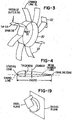
- Fig. 1 is a simplified cross-sectional schematic drawing of a cooling fan.
- Ring 3, also shown in Fig. 2 supports an array of radial stator vanes 6, shown in both Figures.
- Ring 3 is anchored to an external support (not shown).
- Stator vanes 6 in Fig. 1 support an inner ring 9, which is also shown in Fig. 2 .
- Inner ring 9 in Fig. 1 supports a motor, diagrammatically indicated as motor 12, which may be an electric or hydraulic motor.
- Motor 12 drives fan blades 15, which are supported by bearings 18.
- inner ring 9 acts as a perfectly rigid support for the motor 12. However, in practice, this ideal is not attained, and the motor 12 and the inner ring 9 can move in an axial or tangential fashion, which is not desired.
- a given fan system will possess certain natural or resonant frequencies. If an excitation occurs at these frequencies, as when the fan is attached to an automotive engine and the engine vibrates at such frequencies, the fan system will sympathetically vibrate at these frequencies. In general, such sympathetic vibration is not desired.
- a sympathetic vibration of the fan system can be the source of objectionable noise or vibration that can be noticed within the passenger compartment.
- An object of the invention is to provide an improved fan mounting system.
- a motor support is carried by an array of spiral arms, each arm being concave on its radially outer side.
- a motor vehicle may comprises a cooling fan rotatably driven by a motor, the cooling fan comprising a support which carries a motor which drives fan blades and stators coupled to the support, the stators being chordwise concave on a first side and are spanwise concave on a second side.
- an apparatus may comprise a base effective to support a fan motor, a plurality of supports extending from the base, the plurality of supports each redirecting exhaust of the fan and increasing natural frequency of the base-support combination in at least one mode of vibration, compared to a second base-support combination comprising a plurality of radial supports.
- Each of the plurality of stator vanes has at least two sides, both sides being preferably generally arcuate.
- Fig. 3 is a simplified rendition of one form of the invention, showing a motor mount ring 30, which is analogous in function to inner mounting ring 9 in Figs. 1 and 2 .
- stator vanes 33 are attached to the inner ring 9, and also to an outer ring, or individual support members shown as element 32, which is analogous in function to outer ring 3 in Figs. 1 and 2 .
- the stator vanes 33 are constructed with two types of camber.
- Camber generally is illustrated in Fig. 4 , which illustrates a cross-sectional view of an airfoil.
- the mean camber line is the line which is midway between the lower and upper surfaces, with the distance being measured perpendicular to the mean camber line.
- the forwardmost point of the airfoil is the leading edge, and the rearmost point is the trailing edge, as indicated.
- the straight line connecting the leading edge and the trailing edge is the chord line.
- the camber is the maximum distance between the mean camber line and the chord line, as indicated. This type of camber will be called chordwise camber because it is measured with respect to, or along, the chord of the airfoil.
- the vanes 33 are shown by wireframe representations of the mean camber lines of the vanes 33: the vanes 33 are illustrated as having no thickness, and the cross-sections of the vanes are not shown for ease of illustration. Nevertheless, it is understood that the vanes 33 are three-dimensional airfoils. Therefore, one feature of the stator vanes 33 is that they possess chordwise camber.
- a second feature is that the stator vanes 33 have spanwise camber. That is, a span line 58 is defined as the straight line running from the root 52 to the tip 55 of the stator vane 33. Spanwise camber is a distance, measured perpendicular to the span line 58, from the span line 58 to the camber line CL, shown in wire frame. Alternately, spanwise camber can be termed a distance from the span line 58 to the surface (not shown) of the stator vane 33.
- the concavity of the spanwise camber faces counter-clockwise.
- the spanwise concavity of the same blade at the 3 o'clock position is concave upward. That direction is counterclockwise from the vane 33.
- the vanes 33 in Fig. 3 are chordwise concave because they are concave along a chord. Also, the vanes 33 are spanwise concave, because they are concave along the span line 58.
- the pressure side (that is, the bottom side in Fig. 4 ) has a surface running from the leading edge to the trailing edge. That surface in Fig. 3 is concave, and the concavity is bounded by the leading and trailing edges.
- the vanes 33 in Fig. 3 collectively form an array of spiral arms, extending between the inner ring 30 and outer ring 32.
- the arms are concave on their radially outer, RO, sides, as indicated in the Figure.
- Fig. 20 illustrates a chordwise camber as viewed from a rear direction (i.e., as if airflow was coming directly toward the reader out of the page).
- the chordwise positive camber reference direction is the same direction as circumferential travel along the concave path starting at the trailing edge and ending at the leading edge. Notice that by this definition, the positive camber direction is clockwise.
- the direction of chordwise camber can be viewed from the downstream or pressure side, the positive camber reference direction is the same direction as a perpendicular vector V ( Fig. 21 ) starting from the chord line, going towards the mean line. In the illustrations being described, this definition leads to a positive camber direction that is counter-clockwise as illustrated in Fig. 21 .
- chordwise camber direction is by reference to the direction of fan rotation, rather than as a counter-clockwise or clockwise reference. Therefore, alternatively, the camber direction can be referred to as a chordwise positive camber direction that is counter to the direction of fan rotation if the chordwise camber reference direction is as viewed in Fig. 20 , or chordwise positive camber direction is the same as the direction of the rotation of the fan if the definition or reference of the chordwise is that which is referred to in Fig. 21 .
- the definition and reference for the chordwise camber as referred to in Fig. 21 will be used to describe various features of the invention.
- the term sweep or spanwise camber when viewed from a downstream or pressure side of the fan, the spanwise positive camber reference direction is the same direction as the radial travel along a concave path starting at an inner section (small radius) section and ending at a tip section (a large radius) connecting the same features on the inner and outer airfoil cross sections referred to below (that is, both leading edge, or both trailing edge, or both mid-chord locations).
- the spanwise camber direction reference can be linked to the direction of fan rotation.
- the positive spanwise camber direction is the same as the direction of the fan rotation if the reference is the reference or definition referred to in Fig. 22 above as viewed from the downstream side of the fan.
- the reference or definition is that which is shown in Fig. 23 , then a positive spanwise camber direction is counter to the direction of fan rotation.
- vanes 33 in Fig. 3 provides several desirable features. The features were demonstrated by finite element analyses undertaken of (1) radial, chordwise cambered vanes, which lack spanwise camber, such as vane 6 in Fig. 2 (camber is not shown), and (2) dual-cambered vanes of the type shown in Fig. 3 .
- a cyclic axial force was applied to inner ring 9, while outer ring 3 is held stationary.
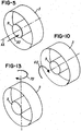
- Fig. 5 illustrates the force 50.
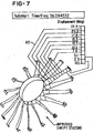
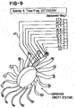
- Figs. 6 and 7 are exaggerated views of the deformation that occurs at the first resonant mode of the vanes 33. The contour magnitudes are not "real,” but give the relative deformation of different parts of the structure with respect to each other. Note also that Figs. 24 - 26 show reduction in out-of-plane and in-plane deformation and Von Mises stress with the dual cambered stators.
- the software used to perform the analysis produced a scale 55, which is displayed on a computer monitor as a multicolored spectrum.
- Fig. 5 is cyclic, and thus the deflection will be cyclic, that is, in-out-in-out.
- Fig. 6 illustrates the deflection occurring at the time of maximum deflection.
- Arrow A2 in Fig. 7 compared with arrow A1 in Fig. 6 , indicate that the deflection of the corresponding regions is smaller for the dual-cambered stators of Fig. 3 .
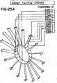
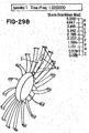
- FIG. 8 and 9 are exaggerated views of the deformation that occurs at higher resonant modes of the structures (mode 2 for the radial stators - Fig 8 , and mode 4 for the dual-cambered stators - Fig. 9 ). Note also that Figs. 27A-27B , 28A-28B and 29B-29B show reduction in out-of-plane and in-plane deformation and Von Mises stress with the dual-cambered stators 33. A comparison of arrow A5 in Fig.
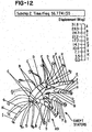
- Figs. 11 and 12 are exaggerated views of the deformation that occurs at higher resonant modes of the structures (mode 3 for the radial stators - Fig. 11 , and mode 2 for the dual-cambered stators - Fig. 12 ).
- Fig. 13 illustrates the gymbaling force 70. It applies a moment about an axis which is perpendicular to the axis AX of the fan in Fig. 5 .
- the drop in natural frequencies associated with the "gymbaling" (out of plane bending) modes with dual-cambered stators implies that these stators are relatively less stiff for these modes. Although there is a loss of stiffness, the out of plane bending modes typically occur at higher frequencies compared to the axial and torsional modes of radial stators, so these frequencies are not that much of a concern from a vehicle application point of view.
- Fig. 11 illustrates the simulation for the case of radial stators.
- Fig. 12 illustrates the case of dual-cambered stators, of the type shown in Fig. 3 .
- a comparison of arrow A7 in Fig. 11 with arrow A9 in Fig. 12 indicates, again, that deflection is less for the dual-cambered stators of Fig. 3 .
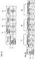
- Fig. 14 is a summary of simulation results.
- Line L1 refers to the situations of Figs. 6 and 7 .
- Line L2 in Fig. 14 refers to the situations of Figs. 8 and 9 .
- Column C1 refers to the radial stators, of Figs. 6 , 8 , and 10 .
- Column C2 refers to the dual-cambered stators of the type shown in Fig. 3 , in the simulations of Figs. 7 , 9 , and 12 .
- Column C3 refers to the change in natural frequency found, between the radial stators and the dual-cambered stators.
- Column C4 refers to the change in global stiffness in the two cases.
- in-phase refers to the fact that, in some deflections, all blades deform into approximately the same shape, as in Fig. 6 for example.
- Out-of-phase refers to the fact that all blades do not deform into the same shapes. For example, blades 80 and 83 in Fig. 11 deform into different shapes.
- Fig. 15 is a summary of results.
- Line L10 refers to axial loading of the type shown in Fig. 5 .
- Line L11 refers to an applied moment, of the type shown in Fig. 10 .
- Block B1 refers to the axial movement of the ring 9. However, this ring 9 does not form the "roots of the stators.” Typically, the "roots" of the stator are the portions that deflect less, which are the tips of the stators 33 at the outer ring (3). “Radial” refers to radial stators. “Swept” refers to the dual-camber stators of Fig. 3 . Block B2 refers to the circumferential movement of the ring 6, or roots of the stators, in the direction of the arrow shown in Fig. 10 . Block B3 refers to the changes in Von Mises Stresses.
- FIG. 16 illustrates one form of the invention.
- a heat exchanger 95 such as a cooling radiator, is present within a motor vehicle 100.
- a fan 110 is present, having dual-cambered stators 115, of the type discussed herein.
- Fig. 17 illustrates a specific embodiment of the stators, in cross-section.
- the tangent 145 to the camber line 135 at the leading edge LE is parallel to the mean incoming airstream 140, at one operating point of the system.
- the direction of the mean incoming airstream 140 will change, as the operating point (that is, engine speed) changes.
- the operating point selected at which parallelism is secured may be (1) the operating point which occurs most often in time, (2) the operating point at which the cooling system requires the maximum volume of cooling airflow, or (3) another desired point.
- the tangent 150 to the camber line 135 at the trailing edge TE is parallel to the axis of rotation AX.
- Fig. 18 is a view, viewed from the direction of arrow E in Fig. 16 .
- the vanes represented by camber lines 135, accept the incoming airstreams 140, which represent the exhaust of the fan 125 in Fig. 16 , and which have a component of motion in the tangential direction.
- Each adjacent pair of vanes cooperates to define an inlet channel, having a central axis CAX.
- the vanes are configured so that the central axis CAX of the inlet channel is parallel to the incoming airstreams 140.
- the vanes redirect the incoming airstreams to be parallel with the axis AX.
- axis of concavity can be defined. In Fig. 4 , such an axis would lie midway between the leading and trailing edges and extend perpendicularly into the paper. For example, if the bottom surface of the airfoil shown were parabolic in shape, concave downward, then the axis of concavity would be a line coincident with the focus of the parabolic surface.
Description
- The invention concerns stator vanes which support a cooling fan motor, such as in an automotive application. The stator vanes have cambered airfoil cross sections and also have camber along their lengths, or spans.
- In particular, the invention refers to a fan assembly as defined in the preamble of
Claim 1. Such a fan assembly is known e.g. fromUS 6 139 265 . -
Fig. 1 is a simplified cross-sectional schematic drawing of a cooling fan.Ring 3, also shown inFig. 2 , supports an array ofradial stator vanes 6, shown in both Figures.Ring 3 is anchored to an external support (not shown).Stator vanes 6 inFig. 1 support aninner ring 9, which is also shown inFig. 2 . It should be understood that the structure identified asring 9 does not have to take the form of a ring or a complete cylindrical 360°body of revolution.Inner ring 9 inFig. 1 supports a motor, diagrammatically indicated asmotor 12, which may be an electric or hydraulic motor.Motor 12drives fan blades 15, which are supported bybearings 18. - Ideally,
inner ring 9 acts as a perfectly rigid support for themotor 12. However, in practice, this ideal is not attained, and themotor 12 and theinner ring 9 can move in an axial or tangential fashion, which is not desired. - Further, a given fan system will possess certain natural or resonant frequencies. If an excitation occurs at these frequencies, as when the fan is attached to an automotive engine and the engine vibrates at such frequencies, the fan system will sympathetically vibrate at these frequencies. In general, such sympathetic vibration is not desired. A sympathetic vibration of the fan system can be the source of objectionable noise or vibration that can be noticed within the passenger compartment.
- Other fan systems of the prior art are disclosed in
US6139265A ,US5342167A ,US2154313A ,FR1499693A EP1312754A andDE4228879A1 . - An object of the invention is to provide an improved fan mounting system.
- The invention is defined in
Claim 1. Further characteristics are contained in the dependent claims. - In one form a motor support is carried by an array of spiral arms, each arm being concave on its radially outer side.
- A motor vehicle may comprises a cooling fan rotatably driven by a motor, the cooling fan comprising a support which carries a motor which drives fan blades and stators coupled to the support, the stators being chordwise concave on a first side and are spanwise concave on a second side.
- Thus an apparatus may comprise a base effective to support a fan motor, a plurality of supports extending from the base, the plurality of supports each redirecting exhaust of the fan and increasing natural frequency of the base-support combination in at least one mode of vibration, compared to a second base-support combination comprising a plurality of radial supports.
- Each of the plurality of stator vanes has at least two sides, both sides being preferably generally arcuate.
- While the form of apparatus herein described constitutes a preferred embodiment of this invention, it is to be understood that the invention is not limited to this precise form of apparatus, and that changes may be made therein without departing from the scope of the invention as defined in the appended claims.
-
-
Fig. 1 is a simplified cross-sectional schematic of a prior-art cooling fan; -
Fig. 2 is a perspective view ofrings Fig. 1 ; -
Fig. 3 is a simplified perspective view of one form of the invention; -
Fig. 4 illustrates conventional terminology used to describe airfoils in the prior art; -
Fig. 5 illustrates an axial force applied during finite element modeling; -
Figs. 6 - 7 illustrate exaggerated views of the deformation that occurs at the first resonant mode of the structures; -
Fig. 8 illustrates simulation results indicating the response of radial stators to the applied moment ofFig. 10 ; -
Fig. 9 illustrates simulation results indicating the response of dual-cambered stators of the type shown inFig. 3 , to the applied moment ofFig. 10 ; -
Fig. 10 illustrates a moment applied about the axis of rotation of the fan, applied during finite element modeling; -
Fig. 11 illustrates simulation results indicating the response of radial stators to the applied gymbaling force ofFig. 13 ; -
Fig. 12 illustrates simulation results indicating the response of dual-cambered stators of the type shown inFig. 3 , to the applied gymbaling force ofFig. 13 ; -
Fig. 13 illustrates a moment applied perpendicular to the axis of rotation of the fan, applied during finite element modeling; -
Figs. 14 and 15 are summaries of results of finite element analyses; -
Fig. 16 illustrates one form of the invention; -
Figs. 17 and 18 illustrate a specific embodiment; -
Fig. 19 illustrates reference directions in a cylindrical coordinate system; -
Figs. 20 - 23 illustrate various references or definitions for spanwise or chordwise camber direction; and -
Figs. 24A - 29B show reduction in out-of-plane and in-plane deformation and Von Mises stress with the dual-cambered stators. -
Fig. 3 is a simplified rendition of one form of the invention, showing a motor mount ring 30, which is analogous in function toinner mounting ring 9 inFigs. 1 and 2 . InFig. 3 ,stator vanes 33 are attached to theinner ring 9, and also to an outer ring, or individual support members shown aselement 32, which is analogous in function toouter ring 3 inFigs. 1 and 2 . - In
Fig. 3 , thestator vanes 33 are constructed with two types of camber. Camber generally is illustrated inFig. 4 , which illustrates a cross-sectional view of an airfoil. The mean camber line is the line which is midway between the lower and upper surfaces, with the distance being measured perpendicular to the mean camber line. The forwardmost point of the airfoil is the leading edge, and the rearmost point is the trailing edge, as indicated. - The straight line connecting the leading edge and the trailing edge is the chord line. The camber is the maximum distance between the mean camber line and the chord line, as indicated. This type of camber will be called chordwise camber because it is measured with respect to, or along, the chord of the airfoil.
- In
Fig. 3 , thevanes 33 are shown by wireframe representations of the mean camber lines of the vanes 33: thevanes 33 are illustrated as having no thickness, and the cross-sections of the vanes are not shown for ease of illustration. Nevertheless, it is understood that thevanes 33 are three-dimensional airfoils. Therefore, one feature of thestator vanes 33 is that they possess chordwise camber. - A second feature is that the
stator vanes 33 have spanwise camber. That is, aspan line 58 is defined as the straight line running from theroot 52 to thetip 55 of thestator vane 33. Spanwise camber is a distance, measured perpendicular to thespan line 58, from thespan line 58 to the camber line CL, shown in wire frame. Alternately, spanwise camber can be termed a distance from thespan line 58 to the surface (not shown) of thestator vane 33. - On the other hand, the concavity of the spanwise camber faces counter-clockwise. For example, the spanwise concavity of the same blade at the 3 o'clock position is concave upward. That direction is counterclockwise from the
vane 33. - From another perspective, the
vanes 33 inFig. 3 are chordwise concave because they are concave along a chord. Also, thevanes 33 are spanwise concave, because they are concave along thespan line 58. - From another perspective, in considering the
vanes 33 as airfoils, the pressure side (that is, the bottom side inFig. 4 ) has a surface running from the leading edge to the trailing edge. That surface inFig. 3 is concave, and the concavity is bounded by the leading and trailing edges. - From another perspective, the
vanes 33 inFig. 3 collectively form an array of spiral arms, extending between the inner ring 30 andouter ring 32. The arms are concave on their radially outer, RO, sides, as indicated in the Figure. - For ease of understanding, Applicants are including several illustrations in
Figs. 20 - 23 .Fig. 20 illustrates a chordwise camber as viewed from a rear direction (i.e., as if airflow was coming directly toward the reader out of the page). When viewed from the downstream or pressure side, the chordwise positive camber reference direction is the same direction as circumferential travel along the concave path starting at the trailing edge and ending at the leading edge. Notice that by this definition, the positive camber direction is clockwise. Alternatively, the direction of chordwise camber can be viewed from the downstream or pressure side, the positive camber reference direction is the same direction as a perpendicular vector V (Fig. 21 ) starting from the chord line, going towards the mean line. In the illustrations being described, this definition leads to a positive camber direction that is counter-clockwise as illustrated inFig. 21 . - Still another way to describe the chordwise camber direction is by reference to the direction of fan rotation, rather than as a counter-clockwise or clockwise reference. Therefore, alternatively, the camber direction can be referred to as a chordwise positive camber direction that is counter to the direction of fan rotation if the chordwise camber reference direction is as viewed in
Fig. 20 , or chordwise positive camber direction is the same as the direction of the rotation of the fan if the definition or reference of the chordwise is that which is referred to inFig. 21 . For ease of illustration and simplicity, the definition and reference for the chordwise camber as referred to inFig. 21 will be used to describe various features of the invention. - For ease of illustration, the term sweep or spanwise camber, when viewed from a downstream or pressure side of the fan, the spanwise positive camber reference direction is the same direction as the radial travel along a concave path starting at an inner section (small radius) section and ending at a tip section (a large radius) connecting the same features on the inner and outer airfoil cross sections referred to below (that is, both leading edge, or both trailing edge, or both mid-chord locations). Note that if this is the same direction as a perpendicular vector starting from a line connecting the same features on the inner and outer airflow cross-section (that is, both leading edge, or both trailing edge, or both mid-chord locations), going towards a concave path starting at the inner section (the smallest radius section) and ending at the tip section (the largest radius section). If this is the reference, then note that the positive camber direction is clockwise as illustrated in
Fig. 23 . - As with the positive chordwise camber, instead of describing the spanwise direction reference as clockwise or counter-clockwise, the spanwise camber direction reference can be linked to the direction of fan rotation. This leads to the alternative definitions which are that the positive spanwise camber direction is the same as the direction of the fan rotation if the reference is the reference or definition referred to in
Fig. 22 above as viewed from the downstream side of the fan. Alternatively, if the reference or definition is that which is shown inFig. 23 , then a positive spanwise camber direction is counter to the direction of fan rotation. - For ease of illustration, the reference of definition referred to in
Fig. 23 will be used in the following part of the description. - The particular structure of the
vanes 33 inFig. 3 provides several desirable features. The features were demonstrated by finite element analyses undertaken of (1) radial, chordwise cambered vanes, which lack spanwise camber, such asvane 6 inFig. 2 (camber is not shown), and (2) dual-cambered vanes of the type shown inFig. 3 . - In one analysis, a cyclic axial force was applied to
inner ring 9, whileouter ring 3 is held stationary.Fig. 5 illustrates theforce 50.Figs. 6 and7 are exaggerated views of the deformation that occurs at the first resonant mode of thevanes 33. The contour magnitudes are not "real," but give the relative deformation of different parts of the structure with respect to each other. Note also thatFigs. 24 - 26 show reduction in out-of-plane and in-plane deformation and Von Mises stress with the dual cambered stators. The software used to perform the analysis produced ascale 55, which is displayed on a computer monitor as a multicolored spectrum. Because the Figures are monochrome drawings, the colored spectrum will not be used, but arrows will connect colored cells in thescale 55 to the corresponding regions of the vanes. For example, arrow A1 indicates a relative deflection in the range of 21.5 to 24.1 units forregion 58. - It should be noted that the
force 50 inFig. 5 is cyclic, and thus the deflection will be cyclic, that is, in-out-in-out.Fig. 6 , and similar Figures, illustrates the deflection occurring at the time of maximum deflection. - Arrow A2 in
Fig. 7 , compared with arrow A1 inFig. 6 , indicate that the deflection of the corresponding regions is smaller for the dual-cambered stators ofFig. 3 . - In the simulations of
Figs. 8 and9 , a moment was applied to theinner ring 9, withouter ring 3 held stationary.Fig. 10 illustrates themoment 60 applied to theinner ring 9.Figs. 8 and9 are exaggerated views of the deformation that occurs at higher resonant modes of the structures (mode 2 for the radial stators -Fig 8 , andmode 4 for the dual-cambered stators -Fig. 9 ). Note also thatFigs. 27A-27B ,28A-28B and29B-29B show reduction in out-of-plane and in-plane deformation and Von Mises stress with the dual-camberedstators 33. A comparison of arrow A5 inFig. 9 with arrow A6 inFig. 8 indicates, again, that deflection is less for the dual-cambered stators ofFig. 3 .Figs. 11 and12 are exaggerated views of the deformation that occurs at higher resonant modes of the structures (mode 3 for the radial stators -Fig. 11 , andmode 2 for the dual-cambered stators -Fig. 12 ). -
Fig. 13 illustrates the gymbaling force 70. It applies a moment about an axis which is perpendicular to the axis AX of the fan inFig. 5 . The drop in natural frequencies associated with the "gymbaling" (out of plane bending) modes with dual-cambered stators implies that these stators are relatively less stiff for these modes. Although there is a loss of stiffness, the out of plane bending modes typically occur at higher frequencies compared to the axial and torsional modes of radial stators, so these frequencies are not that much of a concern from a vehicle application point of view. -
Fig. 11 illustrates the simulation for the case of radial stators.Fig. 12 illustrates the case of dual-cambered stators, of the type shown inFig. 3 . A comparison of arrow A7 inFig. 11 with arrow A9 inFig. 12 indicates, again, that deflection is less for the dual-cambered stators ofFig. 3 . -
Fig. 14 is a summary of simulation results. Line L1 refers to the situations ofFigs. 6 and7 . Line L2 inFig. 14 refers to the situations ofFigs. 8 and9 . - Column C1 refers to the radial stators, of
Figs. 6 ,8 , and10 . Column C2 refers to the dual-cambered stators of the type shown inFig. 3 , in the simulations ofFigs. 7 ,9 , and12 . Column C3 refers to the change in natural frequency found, between the radial stators and the dual-cambered stators. Column C4 refers to the change in global stiffness in the two cases. - In
Fig. 14 , the term "in-phase" refers to the fact that, in some deflections, all blades deform into approximately the same shape, as inFig. 6 for example. "Out-of-phase" refers to the fact that all blades do not deform into the same shapes. For example,blades Fig. 11 deform into different shapes. - Simulations were also done for static loading.
Fig. 15 is a summary of results. Line L10 refers to axial loading of the type shown inFig. 5 . Line L11 refers to an applied moment, of the type shown inFig. 10 . - Block B1 refers to the axial movement of the
ring 9. However, thisring 9 does not form the "roots of the stators." Typically, the "roots" of the stator are the portions that deflect less, which are the tips of thestators 33 at the outer ring (3). "Radial" refers to radial stators. "Swept" refers to the dual-camber stators ofFig. 3 . Block B2 refers to the circumferential movement of thering 6, or roots of the stators, in the direction of the arrow shown inFig. 10 . Block B3 refers to the changes in Von Mises Stresses. -
Fig. 16 illustrates one form of the invention. Aheat exchanger 95, such as a cooling radiator, is present within amotor vehicle 100. Afan 110 is present, having dual-cambered stators 115, of the type discussed herein. -
Fig. 17 illustrates a specific embodiment of the stators, in cross-section. The tangent 145 to thecamber line 135 at the leading edge LE is parallel to the meanincoming airstream 140, at one operating point of the system. The direction of the meanincoming airstream 140 will change, as the operating point (that is, engine speed) changes. The operating point selected at which parallelism is secured may be (1) the operating point which occurs most often in time, (2) the operating point at which the cooling system requires the maximum volume of cooling airflow, or (3) another desired point. - The tangent 150 to the
camber line 135 at the trailing edge TE is parallel to the axis of rotation AX. -
Fig. 18 is a view, viewed from the direction of arrow E inFig. 16 . The vanes, represented bycamber lines 135, accept theincoming airstreams 140, which represent the exhaust of thefan 125 inFig. 16 , and which have a component of motion in the tangential direction. - Each adjacent pair of vanes cooperates to define an inlet channel, having a central axis CAX. The vanes are configured so that the central axis CAX of the inlet channel is parallel to the
incoming airstreams 140. The vanes redirect the incoming airstreams to be parallel with the axis AX. - The term axis of concavity can be defined. In
Fig. 4 , such an axis would lie midway between the leading and trailing edges and extend perpendicularly into the paper. For example, if the bottom surface of the airfoil shown were parabolic in shape, concave downward, then the axis of concavity would be a line coincident with the focus of the parabolic surface. - Numerous substitutions and modifications can be undertaken without departing from the scope of the invention as defined in the following claims.
Claims (12)
- Axial fan assembly, comprising:a) a ring (30) which supports a fan motor (12) which drives fan blades (15), andb) stator vanes (33) which support the ring (30), and which re-direct exhaust of the fan blades (15), the stator vanes (33) havingwherein a positive chordwise camber direction is the direction of a perpendicular vector (V) starting from the chordline of the stator vane (33) and going toward the main line of said stator vane (33),i) a chordwise camber andii) a spanwise camber,
characterised in that a tangential component of the positive chordwise camber direction parallel to the plane of fan rotation is aligned with the direction of fan rotation. - Axial fan assembly according to claim 1, wherein the chordwise camber is concave in a clockwise direction.
- Axial fan assembly according to claim 1, wherein the spanwise camber is concave in a counter-clockwise direction.
- Axial fan assembly according to claim 1, wherein the tangential component of the positive spanwise camber direction is opposed to the component of the positive chordwise camber direction parallel to the plane of fan rotation.
- Axial fan assembly according to claim 1 wherein said fan is mounted in operative relationship to a radiator in a motor vehicle in which the fan is mounted, and used for cooling purposes.
- Axial fan assembly according to claim 1 wherein said stator vanes are chordwise concave on a first side and spanwise concave on a second side.
- Axial fan assembly according to any of preceding claims wherein the vanes (33) are non-radial including at root level.
- Axial fan assembly according to claim 1, wherein each side of each of said plurality of stator vanes (33) has an axis of concavity and the two axes are non-parallel.
- Axial fan assembly according to claim 8, wherein the two axes are perpendicular.
- Axial fan assembly according to claim 1, wherein each of said plurality of stator vanes (33) comprises a concave surface on its radially outside surface.
- Axial fan assembly as recited in claim 1 wherein each of said stator vanes (33) is swept in a predetermined direction that is the same as the direction of rotation of said fan.
- Axial fan assembly as recited in claim 1 wherein each of said plurality of stator vanes (33) comprises a longitudinal cross-section and a width-wise cross-section; said longitudinal cross-section defining a longitudinal radius of curvature that is larger than a width-wise radius of curvature of said width-wise cross section, said longitudinal radius of curvature being in a different direction than said width-wise radius of curvature.
Applications Claiming Priority (2)
| Application Number | Priority Date | Filing Date | Title |
|---|---|---|---|
| US11/380,791 US7832981B2 (en) | 2006-04-28 | 2006-04-28 | Stator vane having both chordwise and spanwise camber |
| PCT/US2007/009856 WO2007127169A1 (en) | 2006-04-28 | 2007-04-24 | Stator vane having both chordwise and spanwise camber |
Publications (2)
| Publication Number | Publication Date |
|---|---|
| EP2013449A1 EP2013449A1 (en) | 2009-01-14 |
| EP2013449B1 true EP2013449B1 (en) | 2018-01-17 |
Family
ID=38477051
Family Applications (1)
| Application Number | Title | Priority Date | Filing Date |
|---|---|---|---|
| EP07755927.6A Not-in-force EP2013449B1 (en) | 2006-04-28 | 2007-04-24 | Axial fan assembly with stator vane having both chordwise and spanwise camber |
Country Status (5)
| Country | Link |
|---|---|
| US (1) | US7832981B2 (en) |
| EP (1) | EP2013449B1 (en) |
| JP (1) | JP2009535556A (en) |
| CN (1) | CN101479443A (en) |
| WO (1) | WO2007127169A1 (en) |
Families Citing this family (12)
| Publication number | Priority date | Publication date | Assignee | Title |
|---|---|---|---|---|
| US8333559B2 (en) * | 2007-04-03 | 2012-12-18 | Carrier Corporation | Outlet guide vanes for axial flow fans |
| US9353765B2 (en) * | 2008-02-20 | 2016-05-31 | Trane International Inc. | Centrifugal compressor assembly and method |
| US8875822B2 (en) * | 2011-05-26 | 2014-11-04 | Chrysler Group Llc | Apparatus and method for pumping air for exhaust oxidation in an internal combustion engine |
| US20130189129A1 (en) * | 2012-01-23 | 2013-07-25 | Lasko Holdings, Inc. | Low Noise Air Movement Generator |
| US10107191B2 (en) | 2012-02-29 | 2018-10-23 | United Technologies Corporation | Geared gas turbine engine with reduced fan noise |
| US20130219922A1 (en) * | 2012-02-29 | 2013-08-29 | Jonathan Gilson | Geared gas turbine engine with reduced fan noise |
| US9716420B2 (en) | 2012-08-28 | 2017-07-25 | Regal Beloit America, Inc. | Fan and electric machine assembly and methods therefor |
| USD742469S1 (en) * | 2014-03-08 | 2015-11-03 | Timothy L. Gall | Annular arrow fletch |
| USD865117S1 (en) * | 2017-04-12 | 2019-10-29 | Security Devices International (Sdi) | Body for a projectile |
| CN108313249A (en) * | 2017-12-20 | 2018-07-24 | 中国船舶重工集团公司第七0研究所 | Pump-jet propulsor lightweight combined-stator conduit and its forming method |
| US11333171B2 (en) | 2018-11-27 | 2022-05-17 | Honeywell International Inc. | High performance wedge diffusers for compression systems |
| US10871170B2 (en) | 2018-11-27 | 2020-12-22 | Honeywell International Inc. | High performance wedge diffusers for compression systems |
Family Cites Families (17)
| Publication number | Priority date | Publication date | Assignee | Title |
|---|---|---|---|---|
| US2154313A (en) | 1938-04-01 | 1939-04-11 | Gen Electric | Directing vane |
| GB1116580A (en) | 1965-11-17 | 1968-06-06 | Bristol Siddeley Engines Ltd | Stator blade assemblies for axial-flow turbine engines |
| US4548548A (en) | 1984-05-23 | 1985-10-22 | Airflow Research And Manufacturing Corp. | Fan and housing |
| DE3609212A1 (en) * | 1986-03-19 | 1987-09-24 | Standard Elektrik Lorenz Ag | AXIAL FAN |
| DE3839009A1 (en) | 1988-11-18 | 1990-05-23 | Opel Adam Ag | COOLING DEVICE FOR AN INTERNAL COMBUSTION ENGINE OF A MOTOR VEHICLE |
| DE4105378A1 (en) | 1991-02-21 | 1992-08-27 | Bosch Gmbh Robert | Axial fan esp. for radiator of motor vehicle engine - avoids emission of siren noise by virtue of angle of struts constituting guide for air flow |
| DE4228879A1 (en) | 1992-08-29 | 1994-03-03 | Asea Brown Boveri | Turbine with axial flow |
| US5342167A (en) | 1992-10-09 | 1994-08-30 | Airflow Research And Manufacturing Corporation | Low noise fan |
| JP3232844B2 (en) | 1993-03-29 | 2001-11-26 | 株式会社デンソー | Blower |
| US5466120A (en) | 1993-03-30 | 1995-11-14 | Nippondenso Co., Ltd. | Blower with bent stays |
| US5577888A (en) | 1995-06-23 | 1996-11-26 | Siemens Electric Limited | High efficiency, low-noise, axial fan assembly |
| US6139265A (en) * | 1996-05-01 | 2000-10-31 | Valeo Thermique Moteur | Stator fan |
| JPH10205497A (en) * | 1996-11-21 | 1998-08-04 | Zexel Corp | Cooling air introducing/discharging device |
| US6045327A (en) * | 1998-05-04 | 2000-04-04 | Carrier Corporation | Axial flow fan assembly and one-piece housing for axial flow fan assembly |
| IT1304683B1 (en) | 1998-10-08 | 2001-03-28 | Gate Spa | AIR CONVEYOR FOR AN ELECTRIC FAN, ESPECIALLY FOR A MOTOR VEHICLE RADIATOR. |
| DE10041805B4 (en) | 2000-08-25 | 2008-06-26 | Conti Temic Microelectronic Gmbh | Cooling device with an air-flowed cooler |
| ITTO20011075A1 (en) | 2001-11-16 | 2003-05-16 | Fiatavio Spa | PALETTE ORGAN, IN PARTICULAR FOR AN AXIAL TURBINE OF AN AIRCRAFT ENGINE. |
-
2006
- 2006-04-28 US US11/380,791 patent/US7832981B2/en active Active
-
2007
- 2007-04-24 CN CNA2007800240747A patent/CN101479443A/en active Pending
- 2007-04-24 WO PCT/US2007/009856 patent/WO2007127169A1/en active Application Filing
- 2007-04-24 JP JP2009507748A patent/JP2009535556A/en active Pending
- 2007-04-24 EP EP07755927.6A patent/EP2013449B1/en not_active Not-in-force
Also Published As
| Publication number | Publication date |
|---|---|
| CN101479443A (en) | 2009-07-08 |
| US20070253808A1 (en) | 2007-11-01 |
| US7832981B2 (en) | 2010-11-16 |
| EP2013449A1 (en) | 2009-01-14 |
| JP2009535556A (en) | 2009-10-01 |
| WO2007127169A1 (en) | 2007-11-08 |
Similar Documents
| Publication | Publication Date | Title |
|---|---|---|
| EP2013449B1 (en) | Axial fan assembly with stator vane having both chordwise and spanwise camber | |
| US10865807B2 (en) | Mistuned fan | |
| JP3832987B2 (en) | Gas turbine engine fan blades | |
| US8801385B2 (en) | Vibration damper device for turbomachine blade attachments, associated turbomachine and associated engines | |
| US6042338A (en) | Detuned fan blade apparatus and method | |
| JP3968234B2 (en) | Row of flow guide elements for turbomachines | |
| US7654793B2 (en) | Fan shroud supports which increase resonant frequency | |
| EP2921648A1 (en) | Gas turbine blade comprising bended leading and trailing edges | |
| US5913661A (en) | Striated hybrid blade | |
| CA2856264C (en) | Blade for axial compressor rotor | |
| JP2002061600A (en) | Platform guide vane having corresponding shape | |
| JPS6232359B2 (en) | ||
| JP2001214893A (en) | Curved barrel aerofoil | |
| EP1510652A2 (en) | Methods and apparatus for reducing vibrations induced to compressor airfoils | |
| JP4216781B2 (en) | Side-flexible interblade platform for turbojet engine vane support | |
| JP6955021B2 (en) | Snubbed wings with improved flutter resistance | |
| ITUB20152313A1 (en) | IMPELLER WITHOUT DISCO FOR TURBOMACCHINA WITH IMPROVED STIFFNESS | |
| CN110612382B (en) | Shrouded blade with improved flutter resistance | |
| JPH0941902A (en) | Blade of rotary fluid machine |
Legal Events
| Date | Code | Title | Description |
|---|---|---|---|
| PUAI | Public reference made under article 153(3) epc to a published international application that has entered the european phase |
Free format text: ORIGINAL CODE: 0009012 |
|
| 17P | Request for examination filed |
Effective date: 20081013 |
|
| AK | Designated contracting states |
Kind code of ref document: A1 Designated state(s): AT BE BG CH CY CZ DE DK EE ES FI FR GB GR HU IE IS IT LI LT LU LV MC MT NL PL PT RO SE SI SK TR |
|
| AX | Request for extension of the european patent |
Extension state: AL BA HR MK RS |
|
| 17Q | First examination report despatched |
Effective date: 20090513 |
|
| DAX | Request for extension of the european patent (deleted) | ||
| GRAP | Despatch of communication of intention to grant a patent |
Free format text: ORIGINAL CODE: EPIDOSNIGR1 |
|
| INTG | Intention to grant announced |
Effective date: 20170519 |
|
| RIN1 | Information on inventor provided before grant (corrected) |
Inventor name: SAVAGE R., JOHN Inventor name: HASAN, ATIF |
|
| GRAS | Grant fee paid |
Free format text: ORIGINAL CODE: EPIDOSNIGR3 |
|
| GRAA | (expected) grant |
Free format text: ORIGINAL CODE: 0009210 |
|
| AK | Designated contracting states |
Kind code of ref document: B1 Designated state(s): AT BE BG CH CY CZ DE DK EE ES FI FR GB GR HU IE IS IT LI LT LU LV MC MT NL PL PT RO SE SI SK TR |
|
| REG | Reference to a national code |
Ref country code: GB Ref legal event code: FG4D |
|
| REG | Reference to a national code |
Ref country code: CH Ref legal event code: EP |
|
| REG | Reference to a national code |
Ref country code: IE Ref legal event code: FG4D |
|
| REG | Reference to a national code |
Ref country code: DE Ref legal event code: R096 Ref document number: 602007053760 Country of ref document: DE Ref country code: AT Ref legal event code: REF Ref document number: 964575 Country of ref document: AT Kind code of ref document: T Effective date: 20180215 |
|
| REG | Reference to a national code |
Ref country code: FR Ref legal event code: PLFP Year of fee payment: 12 |
|
| REG | Reference to a national code |
Ref country code: NL Ref legal event code: MP Effective date: 20180117 |
|
| REG | Reference to a national code |
Ref country code: LT Ref legal event code: MG4D |
|
| REG | Reference to a national code |
Ref country code: AT Ref legal event code: MK05 Ref document number: 964575 Country of ref document: AT Kind code of ref document: T Effective date: 20180117 |
|
| PG25 | Lapsed in a contracting state [announced via postgrant information from national office to epo] |
Ref country code: NL Free format text: LAPSE BECAUSE OF FAILURE TO SUBMIT A TRANSLATION OF THE DESCRIPTION OR TO PAY THE FEE WITHIN THE PRESCRIBED TIME-LIMIT Effective date: 20180117 |
|
| PG25 | Lapsed in a contracting state [announced via postgrant information from national office to epo] |
Ref country code: CY Free format text: LAPSE BECAUSE OF FAILURE TO SUBMIT A TRANSLATION OF THE DESCRIPTION OR TO PAY THE FEE WITHIN THE PRESCRIBED TIME-LIMIT Effective date: 20180117 Ref country code: LT Free format text: LAPSE BECAUSE OF FAILURE TO SUBMIT A TRANSLATION OF THE DESCRIPTION OR TO PAY THE FEE WITHIN THE PRESCRIBED TIME-LIMIT Effective date: 20180117 Ref country code: ES Free format text: LAPSE BECAUSE OF FAILURE TO SUBMIT A TRANSLATION OF THE DESCRIPTION OR TO PAY THE FEE WITHIN THE PRESCRIBED TIME-LIMIT Effective date: 20180117 Ref country code: FI Free format text: LAPSE BECAUSE OF FAILURE TO SUBMIT A TRANSLATION OF THE DESCRIPTION OR TO PAY THE FEE WITHIN THE PRESCRIBED TIME-LIMIT Effective date: 20180117 |
|
| PGFP | Annual fee paid to national office [announced via postgrant information from national office to epo] |
Ref country code: DE Payment date: 20180409 Year of fee payment: 12 |
|
| PG25 | Lapsed in a contracting state [announced via postgrant information from national office to epo] |
Ref country code: LV Free format text: LAPSE BECAUSE OF FAILURE TO SUBMIT A TRANSLATION OF THE DESCRIPTION OR TO PAY THE FEE WITHIN THE PRESCRIBED TIME-LIMIT Effective date: 20180117 Ref country code: AT Free format text: LAPSE BECAUSE OF FAILURE TO SUBMIT A TRANSLATION OF THE DESCRIPTION OR TO PAY THE FEE WITHIN THE PRESCRIBED TIME-LIMIT Effective date: 20180117 Ref country code: PL Free format text: LAPSE BECAUSE OF FAILURE TO SUBMIT A TRANSLATION OF THE DESCRIPTION OR TO PAY THE FEE WITHIN THE PRESCRIBED TIME-LIMIT Effective date: 20180117 Ref country code: BG Free format text: LAPSE BECAUSE OF FAILURE TO SUBMIT A TRANSLATION OF THE DESCRIPTION OR TO PAY THE FEE WITHIN THE PRESCRIBED TIME-LIMIT Effective date: 20180417 Ref country code: GR Free format text: LAPSE BECAUSE OF FAILURE TO SUBMIT A TRANSLATION OF THE DESCRIPTION OR TO PAY THE FEE WITHIN THE PRESCRIBED TIME-LIMIT Effective date: 20180418 Ref country code: IS Free format text: LAPSE BECAUSE OF FAILURE TO SUBMIT A TRANSLATION OF THE DESCRIPTION OR TO PAY THE FEE WITHIN THE PRESCRIBED TIME-LIMIT Effective date: 20180517 Ref country code: SE Free format text: LAPSE BECAUSE OF FAILURE TO SUBMIT A TRANSLATION OF THE DESCRIPTION OR TO PAY THE FEE WITHIN THE PRESCRIBED TIME-LIMIT Effective date: 20180117 |
|
| PGFP | Annual fee paid to national office [announced via postgrant information from national office to epo] |
Ref country code: FR Payment date: 20180426 Year of fee payment: 12 |
|
| REG | Reference to a national code |
Ref country code: DE Ref legal event code: R097 Ref document number: 602007053760 Country of ref document: DE |
|
| PG25 | Lapsed in a contracting state [announced via postgrant information from national office to epo] |
Ref country code: RO Free format text: LAPSE BECAUSE OF FAILURE TO SUBMIT A TRANSLATION OF THE DESCRIPTION OR TO PAY THE FEE WITHIN THE PRESCRIBED TIME-LIMIT Effective date: 20180117 Ref country code: IT Free format text: LAPSE BECAUSE OF FAILURE TO SUBMIT A TRANSLATION OF THE DESCRIPTION OR TO PAY THE FEE WITHIN THE PRESCRIBED TIME-LIMIT Effective date: 20180117 Ref country code: EE Free format text: LAPSE BECAUSE OF FAILURE TO SUBMIT A TRANSLATION OF THE DESCRIPTION OR TO PAY THE FEE WITHIN THE PRESCRIBED TIME-LIMIT Effective date: 20180117 |
|
| PLBE | No opposition filed within time limit |
Free format text: ORIGINAL CODE: 0009261 |
|
| STAA | Information on the status of an ep patent application or granted ep patent |
Free format text: STATUS: NO OPPOSITION FILED WITHIN TIME LIMIT |
|
| PG25 | Lapsed in a contracting state [announced via postgrant information from national office to epo] |
Ref country code: DK Free format text: LAPSE BECAUSE OF FAILURE TO SUBMIT A TRANSLATION OF THE DESCRIPTION OR TO PAY THE FEE WITHIN THE PRESCRIBED TIME-LIMIT Effective date: 20180117 Ref country code: CZ Free format text: LAPSE BECAUSE OF FAILURE TO SUBMIT A TRANSLATION OF THE DESCRIPTION OR TO PAY THE FEE WITHIN THE PRESCRIBED TIME-LIMIT Effective date: 20180117 Ref country code: SK Free format text: LAPSE BECAUSE OF FAILURE TO SUBMIT A TRANSLATION OF THE DESCRIPTION OR TO PAY THE FEE WITHIN THE PRESCRIBED TIME-LIMIT Effective date: 20180117 Ref country code: MC Free format text: LAPSE BECAUSE OF FAILURE TO SUBMIT A TRANSLATION OF THE DESCRIPTION OR TO PAY THE FEE WITHIN THE PRESCRIBED TIME-LIMIT Effective date: 20180117 |
|
| REG | Reference to a national code |
Ref country code: CH Ref legal event code: PL |
|
| REG | Reference to a national code |
Ref country code: BE Ref legal event code: MM Effective date: 20180430 |
|
| 26N | No opposition filed |
Effective date: 20181018 |
|
| GBPC | Gb: european patent ceased through non-payment of renewal fee |
Effective date: 20180424 |
|
| REG | Reference to a national code |
Ref country code: IE Ref legal event code: MM4A |
|
| PG25 | Lapsed in a contracting state [announced via postgrant information from national office to epo] |
Ref country code: LU Free format text: LAPSE BECAUSE OF NON-PAYMENT OF DUE FEES Effective date: 20180424 |
|
| PG25 | Lapsed in a contracting state [announced via postgrant information from national office to epo] |
Ref country code: CH Free format text: LAPSE BECAUSE OF NON-PAYMENT OF DUE FEES Effective date: 20180430 Ref country code: LI Free format text: LAPSE BECAUSE OF NON-PAYMENT OF DUE FEES Effective date: 20180430 Ref country code: BE Free format text: LAPSE BECAUSE OF NON-PAYMENT OF DUE FEES Effective date: 20180430 Ref country code: SI Free format text: LAPSE BECAUSE OF FAILURE TO SUBMIT A TRANSLATION OF THE DESCRIPTION OR TO PAY THE FEE WITHIN THE PRESCRIBED TIME-LIMIT Effective date: 20180117 Ref country code: GB Free format text: LAPSE BECAUSE OF NON-PAYMENT OF DUE FEES Effective date: 20180424 |
|
| PG25 | Lapsed in a contracting state [announced via postgrant information from national office to epo] |
Ref country code: IE Free format text: LAPSE BECAUSE OF NON-PAYMENT OF DUE FEES Effective date: 20180424 |
|
| REG | Reference to a national code |
Ref country code: DE Ref legal event code: R119 Ref document number: 602007053760 Country of ref document: DE |
|
| PG25 | Lapsed in a contracting state [announced via postgrant information from national office to epo] |
Ref country code: DE Free format text: LAPSE BECAUSE OF NON-PAYMENT OF DUE FEES Effective date: 20191101 Ref country code: MT Free format text: LAPSE BECAUSE OF NON-PAYMENT OF DUE FEES Effective date: 20180424 |
|
| PG25 | Lapsed in a contracting state [announced via postgrant information from national office to epo] |
Ref country code: TR Free format text: LAPSE BECAUSE OF FAILURE TO SUBMIT A TRANSLATION OF THE DESCRIPTION OR TO PAY THE FEE WITHIN THE PRESCRIBED TIME-LIMIT Effective date: 20180117 |
|
| PG25 | Lapsed in a contracting state [announced via postgrant information from national office to epo] |
Ref country code: PT Free format text: LAPSE BECAUSE OF FAILURE TO SUBMIT A TRANSLATION OF THE DESCRIPTION OR TO PAY THE FEE WITHIN THE PRESCRIBED TIME-LIMIT Effective date: 20180117 Ref country code: HU Free format text: LAPSE BECAUSE OF FAILURE TO SUBMIT A TRANSLATION OF THE DESCRIPTION OR TO PAY THE FEE WITHIN THE PRESCRIBED TIME-LIMIT; INVALID AB INITIO Effective date: 20070424 |
|
| PG25 | Lapsed in a contracting state [announced via postgrant information from national office to epo] |
Ref country code: FR Free format text: LAPSE BECAUSE OF NON-PAYMENT OF DUE FEES Effective date: 20190430 |