EP2013094B1 - Carton with vent openings - Google Patents
Carton with vent openings Download PDFInfo
- Publication number
- EP2013094B1 EP2013094B1 EP07794525A EP07794525A EP2013094B1 EP 2013094 B1 EP2013094 B1 EP 2013094B1 EP 07794525 A EP07794525 A EP 07794525A EP 07794525 A EP07794525 A EP 07794525A EP 2013094 B1 EP2013094 B1 EP 2013094B1
- Authority
- EP
- European Patent Office
- Prior art keywords
- panel
- end flap
- flap
- carton
- side panel
- Prior art date
- Legal status (The legal status is an assumption and is not a legal conclusion. Google has not performed a legal analysis and makes no representation as to the accuracy of the status listed.)
- Not-in-force
Links
Images


Classifications
-
- B—PERFORMING OPERATIONS; TRANSPORTING
- B65—CONVEYING; PACKING; STORING; HANDLING THIN OR FILAMENTARY MATERIAL
- B65D—CONTAINERS FOR STORAGE OR TRANSPORT OF ARTICLES OR MATERIALS, e.g. BAGS, BARRELS, BOTTLES, BOXES, CANS, CARTONS, CRATES, DRUMS, JARS, TANKS, HOPPERS, FORWARDING CONTAINERS; ACCESSORIES, CLOSURES, OR FITTINGS THEREFOR; PACKAGING ELEMENTS; PACKAGES
- B65D5/00—Rigid or semi-rigid containers of polygonal cross-section, e.g. boxes, cartons or trays, formed by folding or erecting one or more blanks made of paper
- B65D5/42—Details of containers or of foldable or erectable container blanks
- B65D5/4295—Ventilating arrangements, e.g. openings, space elements
-
- B—PERFORMING OPERATIONS; TRANSPORTING
- B65—CONVEYING; PACKING; STORING; HANDLING THIN OR FILAMENTARY MATERIAL
- B65D—CONTAINERS FOR STORAGE OR TRANSPORT OF ARTICLES OR MATERIALS, e.g. BAGS, BARRELS, BOTTLES, BOXES, CANS, CARTONS, CRATES, DRUMS, JARS, TANKS, HOPPERS, FORWARDING CONTAINERS; ACCESSORIES, CLOSURES, OR FITTINGS THEREFOR; PACKAGING ELEMENTS; PACKAGES
- B65D5/00—Rigid or semi-rigid containers of polygonal cross-section, e.g. boxes, cartons or trays, formed by folding or erecting one or more blanks made of paper
- B65D5/42—Details of containers or of foldable or erectable container blanks
- B65D5/54—Lines of weakness to facilitate opening of container or dividing it into separate parts by cutting or tearing
- B65D5/5445—Lines of weakness to facilitate opening of container or dividing it into separate parts by cutting or tearing for dividing a tubular body into separate parts
-
- B—PERFORMING OPERATIONS; TRANSPORTING
- B65—CONVEYING; PACKING; STORING; HANDLING THIN OR FILAMENTARY MATERIAL
- B65D—CONTAINERS FOR STORAGE OR TRANSPORT OF ARTICLES OR MATERIALS, e.g. BAGS, BARRELS, BOTTLES, BOXES, CANS, CARTONS, CRATES, DRUMS, JARS, TANKS, HOPPERS, FORWARDING CONTAINERS; ACCESSORIES, CLOSURES, OR FITTINGS THEREFOR; PACKAGING ELEMENTS; PACKAGES
- B65D2571/00—Bundles of articles held together by packaging elements for convenience of storage or transport, e.g. portable segregating carrier for plural receptacles such as beer cans, pop bottles; Bales of material
- B65D2571/00123—Bundling wrappers or trays
- B65D2571/00129—Wrapper locking means
- B65D2571/00135—Wrapper locking means integral with the wrapper
- B65D2571/00141—Wrapper locking means integral with the wrapper glued
-
- B—PERFORMING OPERATIONS; TRANSPORTING
- B65—CONVEYING; PACKING; STORING; HANDLING THIN OR FILAMENTARY MATERIAL
- B65D—CONTAINERS FOR STORAGE OR TRANSPORT OF ARTICLES OR MATERIALS, e.g. BAGS, BARRELS, BOTTLES, BOXES, CANS, CARTONS, CRATES, DRUMS, JARS, TANKS, HOPPERS, FORWARDING CONTAINERS; ACCESSORIES, CLOSURES, OR FITTINGS THEREFOR; PACKAGING ELEMENTS; PACKAGES
- B65D2571/00—Bundles of articles held together by packaging elements for convenience of storage or transport, e.g. portable segregating carrier for plural receptacles such as beer cans, pop bottles; Bales of material
- B65D2571/00123—Bundling wrappers or trays
- B65D2571/00555—Wrapper opening devices
- B65D2571/00561—Lines of weakness
- B65D2571/00574—Lines of weakness whereby contents can still be carried after the line has been torn
-
- B—PERFORMING OPERATIONS; TRANSPORTING
- B65—CONVEYING; PACKING; STORING; HANDLING THIN OR FILAMENTARY MATERIAL
- B65D—CONTAINERS FOR STORAGE OR TRANSPORT OF ARTICLES OR MATERIALS, e.g. BAGS, BARRELS, BOTTLES, BOXES, CANS, CARTONS, CRATES, DRUMS, JARS, TANKS, HOPPERS, FORWARDING CONTAINERS; ACCESSORIES, CLOSURES, OR FITTINGS THEREFOR; PACKAGING ELEMENTS; PACKAGES
- B65D2571/00—Bundles of articles held together by packaging elements for convenience of storage or transport, e.g. portable segregating carrier for plural receptacles such as beer cans, pop bottles; Bales of material
- B65D2571/00123—Bundling wrappers or trays
- B65D2571/00648—Elements used to form the wrapper
- B65D2571/00654—Blanks
- B65D2571/0066—Blanks formed from one single sheet
Definitions
- the present invention generally relates to a carrier or carton with features, such as ventilation apertures or openings.
- Cartons such as paperboard cartons used to hold, carry or dispense articles are well known. These cartons usually are formed or assembled by folding a paperboard carton blank that has been cut, perforated, and creased in selective areas to achieve desired features and characteristics. These features include tear lines, handles, opening features, dispensers and other attributes. Such opening features can be formed, for example, in the top panel, side panel(s), or other panel, or, alternatively, in an end or ends of the carton.
- end flaps are included on sides of some or all panels and are folded inwardly to close the ends of the carton and enclose articles, such as beverage containers, therewithin. These end flaps can contain opening or dispensing features or can include handles for carrying the carton.
- WO 2005/080218 A discloses a carton according to the preamble of claim 1 and a blank according to the preamble of claim 7.
- the present invention generally relates to a carton with ventilation features formed in a panel or end wall.
- These ventilation openings can be an opening or openings formed in, for example, one end of an enclosed carton, in both ends of an enclosed carton, overlapping from the end into a panel, overlapping through two or more adjacent panels, or be in only one panel.
- the vent openings can include a single opening formed in any end panel or panels, or multiple openings formed in any end or panels, or a combination of these.
- vent openings in general, provide apertures or openings that allow exchange of air between the interior and exterior of the carton to allow for the products within the carton to be “chilled,” “quick chilled,” “heated,” or, in general, to maintain and encourage a temperature exchange as opposed to a fully enclosed carton without the inclusion of such apertures.
- Such apertures can provide temperature exchange of an accelerated nature.
- vent openings can be any shape, such as oval, elliptical, circular, square, triangular, rectangular, quadrilateral, having arced portions, in star formation(s), or any design, trademarked or otherwise, any writing, trademarked or otherwise, or any other shape or design.
- the carton as detailed herein could enclose circular containers that house a yogurt product with the name of the manufacturer, for example, Dannon®, embossed or cut through the end flap that forms a part of an exiting end.
- the openings forming all or parts of the word Dannon® could be formed in either end, any end flap, or any panel.
- the opening can be formed along, between, and/or substantially adjacent the tear line that is used to form an opening in the container.
- the opening or aperture or letters opening can be in a side panel end flap to separate the tear line into a discontinuous or non-continuous tear line that is spaced apart by the aperture, hole, or opening.
- Oval or elliptical apertures are shown in the figures in first side panel end flaps at the exiting end, with one aperture shown along the tear line.
- the tear line extends from the first side panel end flap into and across the first side panel, into and across the top panel, into and across a second side panel, and continues into the second side panel's end flap.
- the tear line is shown as continuing on the other side of the aperture to a peripheral area of the first side panel end flap.
- the present invention can be combined with other carton features, such as opening features formed to dispense articles from the carton.
- the opening shown in the figures herein generally is formed in a top portion of the carton and can include a section of each side panel and a portion of an exiting end.
- the opening generally is formed by separating the tear line to form a remainder carton portion and detachable or hinged dispensing flap portion.
- the side panel end flap portions that remain after the opening is created can provide a retention feature for the enclosed carton to retain articles therein prior to dispensing.
- the dispensing flap is separated along a tear line to form an opening, typically through the initial use, of a finger flap, shown here in the figures in the top panel.
- the opening is created along the tear line in the top panel, the side panels, and in portions of the side panel end flaps.
- the top panel end flap generally is removed in its entirety when the opening is created by separation at the tear line.
- the bottom panel end flaps and the remainder portions of the side panel end flaps, which were not removed by creating of the opening, can remain to form parts or entireties of retention features that retain articles in the carton prior to intended dispensing.
- the present invention can be used, for example, in dispensing articles, which contain products such as food and beverages.
- These articles can include beverage containers such as cans, bottles, and PET containers, as well as other containers being cylindrical, rectangular, parallelepiped, or of any other shape, such as those used in packaging food stuffs.
- a carton blank such as a paperboard blank, which is cut to a specific shape, and creased, scored, cut, or perforated in specific areas is shown.
- the carton blank defines elongate panels between the creases or fold lines, and includes flaps at the respective ends of the panels.
- the carton blank is folded to form a sleeve when fully assembled, so that when the end flaps are closed, the assembled carton has a front or forward end, a rearward end, and a top wall, a bottom wall, front and rear walls, and first and second side walls.
- a paperboard carton sized and dimensioned to contain foodstuffs in cylindrical containers is disclosed.
- the carton of the embodiment illustrated in FIGS. 1-10 is sized to hold 15 articles in either a staggered or a nonstaggered configuration, although the blanks and cartons shown should not be limited to any specific size or dimension.
- blanks and cartons sized and shaped to hold articles of other configurations such as that shown in FIG. 11 which is sized to hold 24 articles, or other sizes such as those that could hold other numbers of articles, such as 6, 8, 10, 21, 30, or more, would work satisfactorily.
- Blanks and cartons that include various unique features, including opening features that provide easy access to the articles, tilt features that position the articles at the front end of the carton, handle features, etc. are also within the present scope
- the blanks and cartons are shown with an opening(s) that can be formed by non-oblique lines, i.e. lines that are shown as perpendicular to some panels and parallel to other panels, and oblique lines.
- the blanks and cartons should not be limited to any specific size, dimension, orientation of the opening features, or opening formed by the opening feature.
- blanks and cartons with an opening feature(s) formed with non-oblique and/or oblique lines that extend through opposing panels, such as from a top panel, through side panels, and that extend to the end panel would work satisfactorily.
- the blanks and cartons shown herein include an end wall configuration that provides an effective barrier to keep the bottles, cans, or articles from rolling out of the formed carton.
- the carton formed from the blank of FIG. 1 includes an opening feature at an exiting end and shows four elliptical apertures, two formed in each of two opposite side panel end flaps.
- the blanks and cartons should not be limited in any manner to the use of only one opening feature or the number of apertures shown in the side panel end flaps.
- the blanks and cartons should not be limited in any manner to the orientation or placement of the aperture or apertures in the side panel end flaps, as such could be in any side panel, top panel, bottom panel, end flap, or in any combination of these.
- the carton can be of various sizes depending upon the number, configuration, and size of containers or product to be stored, enclosed, or dispensed therewithin.
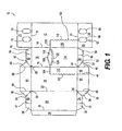
- FIG. 1 illustrates a blank that can be formed into a carton.
- the blank generally is formed into a carton by folding along crease or fold lines to form a carton sleeve with a bottom flap overlapping and adhering to another bottom flap, with a top flap overlapping and adhering to another top flap, or with an adhesive flap overlapping and adhering to a bottom panel, top panel, or side panel.
- the carton blank shown in FIG. 1 can be folded in this manner to form the carton shown in FIGS. 2-10 .
- a securing means such as an adhesive or compound generally is applied to secure the flaps together to form a sleeve.
- end flaps on both ends can be closed.
- the end flaps typically are also held together by glue or other means at the non-exiting end and the end flaps at the exiting end are secured to the top panel end flap with the side panel end flaps only at portions above the tear line.
- the side panel end flaps at the dispensing end also can be attached to the bottom panel end flap.
- FIG. 1 shows a blank 10 that includes a first side panel 12 connected to a top panel 16 by a fold line 14.
- Top panel 16 is connected to a second side panel 20 by a fold line 18.
- Second side panel 20 is connected to a bottom panel 24 by a fold line 22.
- Bottom panel 24 is connected to a securing flap 28 by a fold line 26.
- the securing flap 28 will receive glue and be folded upwardly to be connected to the first side panel 12 or will receive glue on an underside portion and overlap onto first side panel 12. In this manner, either the securing flap 28 or the first side panel 12 can receive the initial glue for securing the securing flap to the first side panel 12.
- end flaps are generally disposed. Specifically, bottom panel 24 is connected to bottom panel end flaps 30 and 34 along fold line 21, second side panel 20 is connected to second side panel end flaps 42 and 46 along fold line 21, top panel end flap 54 is connected to top panel 16 along fold line 21, and first side panel end flaps 60 and 64 are connected to first side panel 12 along fold line 21.
- first side panel end flap 74 is connected to first side panel 12 along fold line 71
- top panel end flaps 76 and 80 are connected to top panel 16 along fold line 71
- second side panel end flap 88 is connected to second side panel 20 along fold line 71
- bottom panel end flaps 96 and 98 are connected to bottom panel 24 along fold line 71.
- Bottom panel end flaps 30 and 34 are connected along a fold line 32.
- Bottom panel end flap 34 is connected to gusset panel 38 by fold line 36 and gusset panel 38 is connected to second side panel end flap 42 along fold line 40.
- Second side panel end flap 46 is connected to gusset panel 50 along fold line 48.
- Gusset panel 50 is connected to top panel end flap 54 along a fold line 52.
- Top panel end flap 54 is connected to top panel end flap 58 along a fold line 56.
- First side panel end flap 60 is connected to first side panel end flap 64 along a tear line 62.
- Top panel end flap 76 is connected to top panel end flap 80 along a fold line 78.
- Top panel end flap 80 is connected to gusset panel 84 along a fold line 82.
- Gusset panel 84 is connected to second side panel end flap 88 along a fold line 86.
- Second side panel end flap 88 is connected to gusset panel 92 along a fold line 90.
- Gusset panel 92 is connected to bottom panel 96 along a fold line 94.
- Bottom panel end flap 96 is connected to bottom panel end flap 98 along a fold line 97.
- Gusset panels 38, 50, 84, and 92 are generally engaged during the construction process and, along with the respective fold lines, enable inward folding of the respective end flaps to create closed ends, which generally occurs once product has been inserted into the sleeve formed from the blank 10.
- apertures 35, 55, 85, and 95 are formed in the gusset panels between respective fold lines to enable folding of the gusset panels to be easier.
- aperture 35 is created between bottom panel 24, bottom panel end flap 34, gusset panel 38, second side panel end flap 42, and second side panel 20.
- Aperture 55 is created between top panel 16, top panel end flap 54, gusset panel 50, second side panel end flap 46, and second side panel 20.
- Aperture 85 is created between top panel 16, top panel end flap 80, gusset panel 84, second side panel end flap 88, and second side panel 20.
- Aperture 95 is created between second side panel 20, second side panel end flap 88, gusset panel 92, bottom panel end flap 96, and bottom panel 24.
- the gusset panels 38, 50, 84, 92, and/or associated apertures 35, 55, 85, 95 may be omitted.
- a dispensing flap 100 can be created in portions of the blank and is shown being generally comprised of a continuous, or a series of substantially continuous, or a series of substantially aligned tear lines, perforations, cut lines, score lines, cut score lines, or any other type oftear line that will enable formation of an aperture in a fully constructed sleeve or carton.
- the dispensing flap 100 can be detached at or along such tear lines to create an opening, can act as a reclosable flap to be detached partially from and remain hingedly attached to the enclosed carton, or can be removed entirely from a remainder portion of the carton.
- dispensing flap 100 includes a tear line 44 between second side panel end flap 42 and second side panel end flap 46.
- the tear line at least partially defining dispensing flap 100 continues from tear line 44 across fold line 21 into second side panel 20 as tear line 102 and proceeds to a turn in second side panel 20 to continue as tear line 104 to and across fold line 18. As shown in FIG. 1 , the turn from tear line 102 to tear line 104 is shown in a general 90-degree orientation, but such tear lines and orientations should not be limited to such configuration.
- the tear line defining the dispensing flap 100 continues as tear line 106 in top panel 16, which is shown with an arcuate configuration that bulges in a convex manner in a direction or manner toward fold line 71 in top panel 16. Tear line 106 continues across top panel 16 to and across fold line 14 to continue along as tear line 108.
- the tear line defining the dispensing flap 100 then turns, in a like manner and shown in a like configuration, though not limited thereto, as tear line 110 in first side panel 12 to and across fold line 21 and into first side panel end flaps to "separate" first side panel end flap 60 from first side panel end flap 64 as tear line 62 that extends to a peripheral portion of the first side panel end flaps.
- the tear line 62 is separated by or at aperture 66 formed in portions of first side panel end flaps 60 and 64.
- Dispensing flap 100 can include portions or panels or subpanels within or along the blank as defined by tear lines 44, 102, 104, 106, 108, 110, and 62. Specifically, subpanel 112 is formed as part of second side panel 20, subpanel 114 is formed as part of top panel 16, and second subpanel 116 is formed as part of first side panel 12, second side panel end flap 46 is formed adjacent second side panel end flap 42 and first side panel end flap 60 is formed adjacent first side end panel 64.
- the dispensing flap 100 can be separated along the tear lines in any known manner, but detachment typically initially starts at finger flap 118, which is shown being formed adjacent, and with a peripheral portion thereof by, tear line 106, and being bounded at an opposite portion by fold lines 120 and 122.
- fold lines 120 and 122 are shown as substantially concentric arcs formed in blank 10 and ease initiation of the finger flap 118 once tear line 106 is separated in top panel 16 to initiate removal or separation of dispensing flap 100 from the carton.
- the blank 10 also includes apertures 66, 68, 70, 72, in first side panel end flaps 60, 64, and 74. These apertures, 66, 68, 70, and 72 are shown in elliptical configurations, but should not be limited in any manner to the size, number, orientation, or position of such apertures. Generally, aperture 66 is shown as separating portions of the tear line 62 from one another, portions of first side panel end flap 60, and portions of the first side panel end flap 64. Apertures 66 and 68 are shown in a generally parallel orientation. Apertures 70 and 72 are also shown in a generally parallel orientation and are formed in portions of first side panel end flap 74. In addition, blank 10 is shown with apertures 66 and 72 parallel to apertures 68 and 70 in reference to fold line 14.
- a user In order to create the opening with the dispensing flap 100, generally, a user will insert a finger or other object into the finger flap 118 or other opening starting feature.
- Alternative configurations of access opening and access opening starting features are contemplated and included herein.
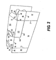
- FIG. 2 shows blank 10 of FIG. 1 being formed into a carton or sleeve.
- Second side panel 20 with corresponding side panel end flaps 42 and 88 are shown in FIG. 2 .
- FIG. 3 shows the other side of the formed carton or sleeve of FIG. 2 with the apertures 66 and 68 in side panel end flaps 60 and 64 and with apertures 70 and 72 in side panel end flap 74.
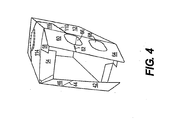
- FIG. 4 shows the exiting end being formed by closing the side panel end flaps.
- side panel end flaps 42 and 46 are closed inwardly with gusset panel 50 and top panel end flap 54 folding about fold line 52 with the cooperation of aperture 55, and gusset panel 38 and bottom panel end flap 34 folding about fold line 36 with the cooperation of aperture 35.
- These flaps and panels are folded inwardly until gusset panel 50 and top panel end flap 54, and gusset panel 38 bottom panel end flap 54 are adjacent.
- glue or another adhesive will be placed onto gusset panel 50 or top panel end flap 54 and onto gusset panel 38 or bottom panel end flap 54 to secure such together at closing of the exiting end.
- Top panel end flap 58 and bottom panel end flap 30 are folded toward one another before closing the exiting end. Sections of the end flaps can be adhered to respective other sections of the other end flaps to create retention features to retain the containers within an enclosed carton until dispensing is desired.
- FIG. 5 shows the enclosed carton with all flaps and panels on the exiting end closed.
- first side panel end flaps 60 and 64 are closed over second side panel end flaps 42 and 46, top panel end flaps 54 and 58, and bottom panel end flaps 30 and 34 to enclose fully the exiting end of the carton.
- the end flaps of the non-exiting end are closed in substantially the same manner as the end flaps of the exiting end, with gusset panels 84 and 92 and top end flaps 76 and 80 and bottom panel end flaps 96 and 98 being closable through interaction with the gussets.
- the non-exiting end can also include vent apertures 70 and 72 in end flap 74 to provide openings to exchange air from the interior of the carton to the exterior of the carton in a manner that is substantially similar to that provided by apertures 66 and 68 at the exiting end.
- the non-exiting end could be modified to be a second exiting end with a second opening area formed by a second dispensing flap, similar or dissimilar to the one formed in the non-exiting end. Such second exiting end could function in a manner similar to the exiting end as detailed hereinabove.
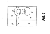
- FIG. 6 shows a front view of the carton of FIG. 5 at the exiting end looking through apertures 66 and 68 through the carton and through apertures 70 and 72 of the non-exiting end.
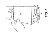
- FIG. 7 shows the finger flap 118 being activated in the top panel 16. The finger flap 118 is shown bounded by tear line 106 and fold lines 120 and 122.
- FIG. 8 shows the removable portion being detached along the tear lines in the top panel 16 and first and second side panels 12 and 20.
- FIG. 9 shows the dispensing flap 100 remaining hingedly attached to the carton at the exiting end.
- the dispensing flap could be hinged to reclose the dispensing flap to cover or reclose the carton.
- the dispensing flap 100 can be entirely removed from the remainder portion of the carton as shown in FIG. 10 by detachment along tear line 62 in first side panel end flaps 60 and 64 and along tear line 44 in second side panel end flaps 42 and 46.
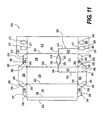
- FIG. 11 shows an alternate blank embodiment that can be formed into a carton.
- the blank generally is formed into a carton by folding along crease or fold lines to form a carton sleeve with a bottom flap overlapping and adhering to another bottom flap, with a top flap overlapping and adhering to another top flap, or with an adhesive flap overlapping and adhering to a bottom panel, top panel, or side panel.
- a securing means such as an adhesive or compound generally is applied to secure the flaps together to form a sleeve.
- the end flaps typically are also held together by glue or other means at the non-exiting end and the end flaps at the exiting end are secured to the top panel end flap with the side panel end flaps only at portions above the tear line.
- the side panel end flaps at the dispensing end also can be attached to the bottom panel end flap.
- FIG. 11 shows a blank 210 that includes a first side panel 212 connected to a top panel 216 by a fold line 214.
- Top panel 216 is connected to a second side panel 220 by a fold line 218.
- Second side panel 220 is connected to a bottom panel 224 by a fold line 222.
- Bottom panel 224 is connected to a securing flap 228 by a fold line 226.
- the securing flap 228 will receive glue and be folded upwardly to be connected to the first side panel 212 or will receive glue on an underside portion and overlap onto first side panel 212. In this manner, either the securing flap 228 or the first side panel 212 can receive the initial glue for securing the securing flap to the first side panel 212.
- end flaps are generally disposed. Specifically, bottom panel 224 is connected to bottom panel end flaps 230 and 234 along fold line 221, second side panel 220 is connected to second side panel end flaps 242 and 246 along fold line 221, top panel end flap 254 is connected to top panel 216 along fold line 221, and first side panel end flaps 260 and 264 are connected to first side panel 212 along fold line 221.
- first side panel end flap 274 is connected to first side panel 212 along fold line 271
- top panel end flaps 276 and 280 are connected to top panel 216 along fold line 271
- second side panel end flap 288 is connected to second side panel 220 along fold line 271
- bottom panel end flaps 296 and 298 are connected to bottom panel 224 along fold line 271.
- Bottom panel end flaps 230 and 234 are connected along a fold line 232.
- Bottom panel end flap 234 is connected to gusset panel 238 by fold line 236 and gusset panel 238 is connected to second side panel end flap 242 along fold line 240.
- Second side panel end flap 246 is connected to gusset panel 250 along fold line 248.
- Gusset panel 250 is connected to top panel end flap 254 along a fold line 252.
- Top panel end flap 254 is connected to top panel end flap 258 along a fold line 256.
- First side panel end flap 260 is connected to first side panel end flap 264 along a tear line 262.
- Top panel end flap 276 is connected to top panel end flap 280 along a fold line 278.
- Top panel end flap 280 is connected to gusset panel 284 along a fold line 282.
- Gusset panel 284 is connected to second side panel end flap 288 along a fold line 286.
- Second side panel end flap 288 is connected to gusset panel 292 along a fold line 290.
- Gusset panel 292 is connected to bottom panel 296 along a fold line 294.
- Bottom panel end flap 296 is connected to bottom panel end flap 298 along a fold line 297.
- Gusset panels 238, 250, 284, and 292 are generally engaged during the construction process and, along with the respective fold lines, enable inward folding of the respective end flaps to create closed ends, which generally occurs once product has been inserted into the sleeve formed from the blank 210.
- apertures 235, 255, 285, and 295 are formed in the gusset panels between respective fold lines to enable folding of the gusset panels to be easier.
- aperture 235 is created between bottom panel 224, bottom panel end flap 234, gusset panel 238, second side panel end flap 242, and second side panel 220.
- Aperture 255 is created between top panel 216, top panel end flap 254, gusset panel 250, second side panel end flap 246, and second side panel 220.
- Aperture 285 is created between top panel 216, top panel end flap 280, gusset panel 284, second side panel end flap 288, and second side panel 220.
- Aperture 295 is created between second side panel 220, second side panel end flap 288, gusset panel 292, bottom panel end flap 296, and bottom panel 224.
- the gusset panels 238, 250, 284, 292 and/or associated apertures 235, 255, 285, 295 may be omitted.
- a dispensing flap 300 can be created in portions of the blank and is shown being generally comprised of a continuous, or a series of substantial ly continuous, or a series of substantially aligned tear lines, perforations, cut lines, score lines, cut score lines, or any other type of tear line that will enable formation of an aperture in a fully constructed sleeve or carton.
- the dispensing flap 300 can be detached at or along such tear lines to create an opening, can act as a reclosable flap to be detached partially from and remain hingedly attached to the enclosed carton, or can be removed entirely from a remainder portion of the carton.
- Dispensing flap 300 includes a tear line 244 between second side panel end flap 242 and second side panel end flap 246.
- the tear line at least partially defining dispensing flap 300 continues from tear line 244 across fold line 22 into second side panel 220 as tear line 302 and proceeds to a turn in second side panel 220 to continue as tear line 304 to and across fold line 218.
- the turn from tear line 302 to tear line 304 is shown in a general 90-degree orientation, but such tear lines and orientations should not be limited to such configuration.
- the tear line defining the dispensing flap 300 continues as tear line 306 in top panel 216, which is shown with an arcuate configuration that bulges in a convex manner in a direction or manner toward fold line 271 in top panel 216. Tear line 306 continues across top panel 216 to and across fold line 214 to continue along as tear line 308.
- the tear line defining the dispensing flap 300 then turns, in a like manner and shown in a like configuration, though not limited thereto, as tear line 310 in first side panel 212 to and across fold line 221 and into first side panel end flaps to "separate" first side panel end flap 260 from first side panel end flap 264 as tear line 262 that extends to a peripheral portion of the first side panel end flaps.
- the tear line 262 is separated by or at aperture 266 formed in portions of first side panel end flaps 260 and 264.
- Dispensing flap 300 can include portions or panels or subpanels within or along the blank as defined by tear lines 244, 302, 304, 306, 308, 310, and 262. Specifically, subpanel 312 is formed as part of second side panel 220, subpanel 314 is formed as part of top panel 216, and second subpanel 316 is formed as part of first side panel 212, second side panel end flap 246 is formed adjacent second side panel end flap 242 and first side panel end flap 260 is formed adjacent first side end panel 264.
- the dispensing flap 300 can be separated along the tear lines in any known manner, but detachment typically initially starts at finger flap 318, which is shown being formed adjacent, and with a peripheral portion thereof by, tear line 306, and being bounded at an opposite portion by fold lines 320 and 322.
- fold lines 320 and 322 are shown as substantially concentric arcs formed in blank 210 and ease initiation of the finger flap 318 once tear line 306 is separated in top panel 216 to initiate removal or separation of dispensing flap 300 from the carton.
- the blank 210 also includes apertures 266, 268, 270, and 272 in first side panel end flaps 260, 264, and 274. These apertures 266, 268, 270, and 272 are shown in elliptical configurations, but should not be limited in any manner to the size, number, orientation, or position of such apertures.
- aperture 266 is shown as separating portions of tear line 262, portions of first side panel end flap 260, and portions of the first side panel end flap 264.
- Apertures 266 and 268 are shown in a generally parallel orientation.
- Apertures 270 and 272 are also shown in a generally parallel orientation and are formed in portions of first side panel end flap 274.
- blank 210 is shown with apertures 266 and 272 parallel to apertures 268 and 270 in reference to fold line 214.
- a user will insert a finger or other object into the finger flap 118 or other opening starting feature.
- Alternative configurations of access opening and access opening starting features are contemplated and included herein.
- FIGS. 1 and 11 are exemplary dimensions that may be altered, for example, to accommodate various container forms or types, diverse container types or sizes, diverse container types or sizes enclosed within a single carton (e.g. large and small, short and tall, containers in a single enclosed carton).
- the present blanks or cartons can be formed, for example, from coated paperboard and similar materials.
- the interior and/or exterior sides of the blanks or cartons can be coated with a clay coating.
- the clay coating may then be printed over with product, advertising, price coding, and other information or images.
- the blanks or cartons may then be coated with a varnish to protect any information printed on the blanks or cartons.
- the blanks or cartons may also be coated with, for example, a moisture barrier layer, on either or both sides of the blanks or cartons.
- the blanks or cartons may be constructed of paperboard of a caliper such that it is heavier and more rigid than ordinary paper.
- the blanks or cartons can also be constructed of other materials, such as cardboard, hard paper, or any other material having properties suitable for enabling the carrier package to function at least generally as described above.
- the blanks or cartons can also be laminated to, or coated with, one or more sheet-like materials at selected panels or panel sections.
- fold or tear lines detailed herein can be any substantially linear, although not necessarily straight, form of weakening, such as those that facilitate folding therealong. More specifically, but not for the purpose of narrowing scope thereof, fold and tear lines include: a score line, such as lines formed with a blunt scoring knife, or the like, which creates a crushed portion in the material along the desired line of weakness; a cut that extends partially into a material along the desired line of weakness, and/or a series of cuts that extend partially into and/or completely through the material along the desired line of weakness; and various combinations of these features. In situations where cutting is used to create a fold line, typically the cutting will not be overly extensive in a manner that might cause a reasonable user to consider incorrectly the fold line to be a tear line.
- the present blanks or cartons may be described as having one or panels adhered together by glue.
- glue is intended to encompass all manner of adhesives commonly used to secure carton panels in place.
Abstract
Description
- This application claims the benefit of
U.S. Provisional Application No. 60/797,508, filed May 4, 2006 - The present invention generally relates to a carrier or carton with features, such as ventilation apertures or openings.
- Cartons, such as paperboard cartons used to hold, carry or dispense articles are well known. These cartons usually are formed or assembled by folding a paperboard carton blank that has been cut, perforated, and creased in selective areas to achieve desired features and characteristics. These features include tear lines, handles, opening features, dispensers and other attributes. Such opening features can be formed, for example, in the top panel, side panel(s), or other panel, or, alternatively, in an end or ends of the carton.
- When fabricating a carrier or carton from the paperboard carton blank, opposite ends of the blank typically are attached to each other by glue or other adhesive, e.g. to form the bottom panel of the carrier. End flaps are included on sides of some or all panels and are folded inwardly to close the ends of the carton and enclose articles, such as beverage containers, therewithin. These end flaps can contain opening or dispensing features or can include handles for carrying the carton.
-
WO 2005/080218 A discloses a carton according to the preamble of claim 1 and a blank according to the preamble of claim 7. - The present invention generally relates to a carton with ventilation features formed in a panel or end wall. These ventilation openings can be an opening or openings formed in, for example, one end of an enclosed carton, in both ends of an enclosed carton, overlapping from the end into a panel, overlapping through two or more adjacent panels, or be in only one panel. The vent openings can include a single opening formed in any end panel or panels, or multiple openings formed in any end or panels, or a combination of these. The vent openings, in general, provide apertures or openings that allow exchange of air between the interior and exterior of the carton to allow for the products within the carton to be "chilled," "quick chilled," "heated," or, in general, to maintain and encourage a temperature exchange as opposed to a fully enclosed carton without the inclusion of such apertures. Such apertures can provide temperature exchange of an accelerated nature.
- These vent openings can be any shape, such as oval, elliptical, circular, square, triangular, rectangular, quadrilateral, having arced portions, in star formation(s), or any design, trademarked or otherwise, any writing, trademarked or otherwise, or any other shape or design. For example, the carton as detailed herein, could enclose circular containers that house a yogurt product with the name of the manufacturer, for example, Dannon®, embossed or cut through the end flap that forms a part of an exiting end. The openings forming all or parts of the word Dannon® could be formed in either end, any end flap, or any panel. As another example, if the carton as detailed herein was shaped in size to hold circular cans with a beverage contained therewithin, Coca Cola® could be embossed or cut through one of the end panel flaps. When the aperture of any size, or the design or lettering, such as for identifying the product manufacturer is included as an aperture in a panel or end flap, generally the opening can be formed along, between, and/or substantially adjacent the tear line that is used to form an opening in the container. The opening or aperture or letters opening can be in a side panel end flap to separate the tear line into a discontinuous or non-continuous tear line that is spaced apart by the aperture, hole, or opening. Oval or elliptical apertures are shown in the figures in first side panel end flaps at the exiting end, with one aperture shown along the tear line. The tear line extends from the first side panel end flap into and across the first side panel, into and across the top panel, into and across a second side panel, and continues into the second side panel's end flap. The tear line is shown as continuing on the other side of the aperture to a peripheral area of the first side panel end flap.
- The present invention can be combined with other carton features, such as opening features formed to dispense articles from the carton. The opening shown in the figures herein generally is formed in a top portion of the carton and can include a section of each side panel and a portion of an exiting end. The opening generally is formed by separating the tear line to form a remainder carton portion and detachable or hinged dispensing flap portion. The side panel end flap portions that remain after the opening is created can provide a retention feature for the enclosed carton to retain articles therein prior to dispensing.
- To dispense from the formed carton, the dispensing flap is separated along a tear line to form an opening, typically through the initial use, of a finger flap, shown here in the figures in the top panel. The opening is created along the tear line in the top panel, the side panels, and in portions of the side panel end flaps. The top panel end flap generally is removed in its entirety when the opening is created by separation at the tear line. The bottom panel end flaps and the remainder portions of the side panel end flaps, which were not removed by creating of the opening, can remain to form parts or entireties of retention features that retain articles in the carton prior to intended dispensing.
- The present invention can be used, for example, in dispensing articles, which contain products such as food and beverages. These articles can include beverage containers such as cans, bottles, and PET containers, as well as other containers being cylindrical, rectangular, parallelepiped, or of any other shape, such as those used in packaging food stuffs.
-
-
FIG. 1 is a plan view of a blank from which a carton can be formed in accordance with one embodiment. -
FIG. 2 shows the blank ofFIG. 1 formed into a sleeve. -
FIG. 3 shows the opposite view of the sleeve ofFIG. 2 and the apertures in the end flaps. -
FIG. 4 shows an exiting end with the gusset flaps being closed. -
FIG. 5 shows a perspective view of the closed exiting end of the carton. -
FIG. 6 shows a front view of the carton ofFIG. 5 with vent apertures in the exiting end and in the non-exiting end. -
FIG. 7 shows the finger flap being activated in the top panel. -
FIG. 8 shows the removable portion being detached along the tear line. -
FIG. 9 shows the removable portion remaining hingedly attached to the carton. -
FIG. 10 shows the removable portion entirely removed from the carton. -
FIG. 11 shows an alternate embodiment of a blank that can be formed into a carton. - For a more complete understanding, reference should be made to the following detailed description and accompanying drawings, wherein like reference numerals designate corresponding parts throughout the figures.
- Among other things, a carton blank, such as a paperboard blank, which is cut to a specific shape, and creased, scored, cut, or perforated in specific areas is shown. The carton blank defines elongate panels between the creases or fold lines, and includes flaps at the respective ends of the panels. The carton blank is folded to form a sleeve when fully assembled, so that when the end flaps are closed, the assembled carton has a front or forward end, a rearward end, and a top wall, a bottom wall, front and rear walls, and first and second side walls.
- For purposes of illustration, a paperboard carton sized and dimensioned to contain foodstuffs in cylindrical containers is disclosed. The carton of the embodiment illustrated in
FIGS. 1-10 is sized to hold 15 articles in either a staggered or a nonstaggered configuration, although the blanks and cartons shown should not be limited to any specific size or dimension. For example, blanks and cartons sized and shaped to hold articles of other configurations, such as that shown inFIG. 11 which is sized to hold 24 articles, or other sizes such as those that could hold other numbers of articles, such as 6, 8, 10, 21, 30, or more, would work satisfactorily. Blanks and cartons that include various unique features, including opening features that provide easy access to the articles, tilt features that position the articles at the front end of the carton, handle features, etc. are also within the present scope - Also for purposes of illustration, the blanks and cartons are shown with an opening(s) that can be formed by non-oblique lines, i.e. lines that are shown as perpendicular to some panels and parallel to other panels, and oblique lines. However, the blanks and cartons should not be limited to any specific size, dimension, orientation of the opening features, or opening formed by the opening feature. For example, blanks and cartons with an opening feature(s) formed with non-oblique and/or oblique lines that extend through opposing panels, such as from a top panel, through side panels, and that extend to the end panel would work satisfactorily. In addition, for purposes of illustration, the blanks and cartons shown herein include an end wall configuration that provides an effective barrier to keep the bottles, cans, or articles from rolling out of the formed carton.
- As shown in
FIGS. 2-10 , the carton formed from the blank ofFIG. 1 includes an opening feature at an exiting end and shows four elliptical apertures, two formed in each of two opposite side panel end flaps. However, one of ordinary skill in the art will understand that the blanks and cartons should not be limited in any manner to the use of only one opening feature or the number of apertures shown in the side panel end flaps. Additionally, the blanks and cartons should not be limited in any manner to the orientation or placement of the aperture or apertures in the side panel end flaps, as such could be in any side panel, top panel, bottom panel, end flap, or in any combination of these. One of ordinary skill in the art will also understand that the carton can be of various sizes depending upon the number, configuration, and size of containers or product to be stored, enclosed, or dispensed therewithin. -
FIG. 1 illustrates a blank that can be formed into a carton. The blank generally is formed into a carton by folding along crease or fold lines to form a carton sleeve with a bottom flap overlapping and adhering to another bottom flap, with a top flap overlapping and adhering to another top flap, or with an adhesive flap overlapping and adhering to a bottom panel, top panel, or side panel. The carton blank shown inFIG. 1 can be folded in this manner to form the carton shown inFIGS. 2-10 . A securing means, such as an adhesive or compound generally is applied to secure the flaps together to form a sleeve. Once the carton is formed into the sleeve, articles, such as bottles, cans, or the like can be placed into the sleeve and the end flaps on both ends can be closed. The end flaps typically are also held together by glue or other means at the non-exiting end and the end flaps at the exiting end are secured to the top panel end flap with the side panel end flaps only at portions above the tear line. The side panel end flaps at the dispensing end also can be attached to the bottom panel end flap. -
FIG. 1 shows a blank 10 that includes afirst side panel 12 connected to atop panel 16 by afold line 14.Top panel 16 is connected to asecond side panel 20 by afold line 18.Second side panel 20 is connected to abottom panel 24 by afold line 22.Bottom panel 24 is connected to a securingflap 28 by afold line 26. In one possible scenario, generally, the securingflap 28 will receive glue and be folded upwardly to be connected to thefirst side panel 12 or will receive glue on an underside portion and overlap ontofirst side panel 12. In this manner, either the securingflap 28 or thefirst side panel 12 can receive the initial glue for securing the securing flap to thefirst side panel 12. - Along peripheral portions of the
panels transverse fold lines bottom panel 24 is connected to bottom panel end flaps 30 and 34 alongfold line 21,second side panel 20 is connected to second side panel end flaps 42 and 46 alongfold line 21, toppanel end flap 54 is connected totop panel 16 alongfold line 21, and first side panel end flaps 60 and 64 are connected tofirst side panel 12 alongfold line 21. On the opposite side of the blank 10, first sidepanel end flap 74 is connected tofirst side panel 12 alongfold line 71, top panel end flaps 76 and 80 are connected totop panel 16 alongfold line 71, second sidepanel end flap 88 is connected tosecond side panel 20 alongfold line 71, and bottom panel end flaps 96 and 98 are connected tobottom panel 24 alongfold line 71. - Bottom panel end flaps 30 and 34 are connected along a
fold line 32. Bottompanel end flap 34 is connected togusset panel 38 byfold line 36 andgusset panel 38 is connected to second sidepanel end flap 42 alongfold line 40. Second sidepanel end flap 46 is connected togusset panel 50 alongfold line 48.Gusset panel 50 is connected to toppanel end flap 54 along afold line 52. Toppanel end flap 54 is connected to toppanel end flap 58 along afold line 56. First sidepanel end flap 60 is connected to first sidepanel end flap 64 along atear line 62. Toppanel end flap 76 is connected to toppanel end flap 80 along afold line 78. Toppanel end flap 80 is connected togusset panel 84 along afold line 82.Gusset panel 84 is connected to second sidepanel end flap 88 along afold line 86. Second sidepanel end flap 88 is connected togusset panel 92 along afold line 90.Gusset panel 92 is connected tobottom panel 96 along afold line 94. Bottompanel end flap 96 is connected to bottompanel end flap 98 along afold line 97. -
Gusset panels apertures aperture 35 is created betweenbottom panel 24, bottompanel end flap 34,gusset panel 38, second sidepanel end flap 42, andsecond side panel 20.Aperture 55 is created betweentop panel 16, toppanel end flap 54,gusset panel 50, second sidepanel end flap 46, andsecond side panel 20.Aperture 85 is created betweentop panel 16, toppanel end flap 80,gusset panel 84, second sidepanel end flap 88, andsecond side panel 20.Aperture 95 is created betweensecond side panel 20, second sidepanel end flap 88,gusset panel 92, bottompanel end flap 96, andbottom panel 24. Alternatively, thegusset panels apertures - A dispensing
flap 100 can be created in portions of the blank and is shown being generally comprised of a continuous, or a series of substantially continuous, or a series of substantially aligned tear lines, perforations, cut lines, score lines, cut score lines, or any other type oftear line that will enable formation of an aperture in a fully constructed sleeve or carton. Generally, the dispensingflap 100 can be detached at or along such tear lines to create an opening, can act as a reclosable flap to be detached partially from and remain hingedly attached to the enclosed carton, or can be removed entirely from a remainder portion of the carton. As shown inFIG. 1 , dispensingflap 100 includes atear line 44 between second sidepanel end flap 42 and second sidepanel end flap 46. The tear line at least partially defining dispensingflap 100 continues fromtear line 44 acrossfold line 21 intosecond side panel 20 astear line 102 and proceeds to a turn insecond side panel 20 to continue astear line 104 to and acrossfold line 18. As shown inFIG. 1 , the turn fromtear line 102 to tearline 104 is shown in a general 90-degree orientation, but such tear lines and orientations should not be limited to such configuration. The tear line defining the dispensingflap 100 continues astear line 106 intop panel 16, which is shown with an arcuate configuration that bulges in a convex manner in a direction or manner towardfold line 71 intop panel 16.Tear line 106 continues acrosstop panel 16 to and acrossfold line 14 to continue along astear line 108. The tear line defining the dispensingflap 100 then turns, in a like manner and shown in a like configuration, though not limited thereto, astear line 110 infirst side panel 12 to and acrossfold line 21 and into first side panel end flaps to "separate" first sidepanel end flap 60 from first sidepanel end flap 64 astear line 62 that extends to a peripheral portion of the first side panel end flaps. Generally, thetear line 62 is separated by or ataperture 66 formed in portions of first side panel end flaps 60 and 64. -
Dispensing flap 100 can include portions or panels or subpanels within or along the blank as defined bytear lines subpanel 112 is formed as part ofsecond side panel 20,subpanel 114 is formed as part oftop panel 16, andsecond subpanel 116 is formed as part offirst side panel 12, second sidepanel end flap 46 is formed adjacent second sidepanel end flap 42 and first sidepanel end flap 60 is formed adjacent firstside end panel 64. - The dispensing
flap 100 can be separated along the tear lines in any known manner, but detachment typically initially starts atfinger flap 118, which is shown being formed adjacent, and with a peripheral portion thereof by,tear line 106, and being bounded at an opposite portion byfold lines lines finger flap 118 oncetear line 106 is separated intop panel 16 to initiate removal or separation of dispensingflap 100 from the carton. - The blank 10 also includes
apertures aperture 66 is shown as separating portions of thetear line 62 from one another, portions of first sidepanel end flap 60, and portions of the first sidepanel end flap 64. Apertures 66 and 68 are shown in a generally parallel orientation. Apertures 70 and 72 are also shown in a generally parallel orientation and are formed in portions of first sidepanel end flap 74. In addition, blank 10 is shown withapertures apertures line 14. - In order to create the opening with the dispensing
flap 100, generally, a user will insert a finger or other object into thefinger flap 118 or other opening starting feature. Alternative configurations of access opening and access opening starting features are contemplated and included herein. -
FIG. 2 shows blank 10 ofFIG. 1 being formed into a carton or sleeve.Second side panel 20 with corresponding side panel end flaps 42 and 88 are shown inFIG. 2 .FIG. 3 shows the other side of the formed carton or sleeve ofFIG. 2 with theapertures apertures panel end flap 74. -
FIG. 4 shows the exiting end being formed by closing the side panel end flaps.
As shown inFIG. 4 , side panel end flaps 42 and 46 are closed inwardly withgusset panel 50 and toppanel end flap 54 folding aboutfold line 52 with the cooperation ofaperture 55, andgusset panel 38 and bottompanel end flap 34 folding aboutfold line 36 with the cooperation ofaperture 35. These flaps and panels are folded inwardly untilgusset panel 50 and toppanel end flap 54, andgusset panel 38 bottompanel end flap 54 are adjacent. Generally, during manufacture or prior to folding blank 10, glue or another adhesive will be placed ontogusset panel 50 or toppanel end flap 54 and ontogusset panel 38 or bottompanel end flap 54 to secure such together at closing of the exiting end. Toppanel end flap 58 and bottompanel end flap 30 are folded toward one another before closing the exiting end. Sections of the end flaps can be adhered to respective other sections of the other end flaps to create retention features to retain the containers within an enclosed carton until dispensing is desired. -
FIG. 5 shows the enclosed carton with all flaps and panels on the exiting end closed. Following the progression of end flap closing fromFIG. 4 , first side panel end flaps 60 and 64 are closed over second side panel end flaps 42 and 46, top panel end flaps 54 and 58, and bottom panel end flaps 30 and 34 to enclose fully the exiting end of the carton. The end flaps of the non-exiting end are closed in substantially the same manner as the end flaps of the exiting end, withgusset panels vent apertures end flap 74 to provide openings to exchange air from the interior of the carton to the exterior of the carton in a manner that is substantially similar to that provided byapertures -
FIG. 6 shows a front view of the carton ofFIG. 5 at the exiting end looking throughapertures apertures FIG. 7 shows thefinger flap 118 being activated in thetop panel 16. Thefinger flap 118 is shown bounded bytear line 106 and foldlines FIG. 8 shows the removable portion being detached along the tear lines in thetop panel 16 and first andsecond side panels -
FIG. 9 shows the dispensingflap 100 remaining hingedly attached to the carton at the exiting end. The dispensing flap could be hinged to reclose the dispensing flap to cover or reclose the carton. Alternatively, the dispensingflap 100 can be entirely removed from the remainder portion of the carton as shown inFIG. 10 by detachment alongtear line 62 in first side panel end flaps 60 and 64 and alongtear line 44 in second side panel end flaps 42 and 46. -
FIG. 11 shows an alternate blank embodiment that can be formed into a carton. The blank generally is formed into a carton by folding along crease or fold lines to form a carton sleeve with a bottom flap overlapping and adhering to another bottom flap, with a top flap overlapping and adhering to another top flap, or with an adhesive flap overlapping and adhering to a bottom panel, top panel, or side panel. A securing means, such as an adhesive or compound generally is applied to secure the flaps together to form a sleeve. Once the carton is formed into the sleeve, articles, such as bottles, cans, or the like can be placed into the sleeve and the end flaps on both ends can be closed. The end flaps typically are also held together by glue or other means at the non-exiting end and the end flaps at the exiting end are secured to the top panel end flap with the side panel end flaps only at portions above the tear line. The side panel end flaps at the dispensing end also can be attached to the bottom panel end flap. -
FIG. 11 shows a blank 210 that includes afirst side panel 212 connected to atop panel 216 by afold line 214.Top panel 216 is connected to asecond side panel 220 by afold line 218.Second side panel 220 is connected to abottom panel 224 by afold line 222.Bottom panel 224 is connected to a securingflap 228 by afold line 226. In one possible scenario, generally, the securingflap 228 will receive glue and be folded upwardly to be connected to thefirst side panel 212 or will receive glue on an underside portion and overlap ontofirst side panel 212. In this manner, either the securingflap 228 or thefirst side panel 212 can receive the initial glue for securing the securing flap to thefirst side panel 212. - Along peripheral portions of the
panels transverse fold lines bottom panel 224 is connected to bottom panel end flaps 230 and 234 alongfold line 221,second side panel 220 is connected to second side panel end flaps 242 and 246 alongfold line 221, toppanel end flap 254 is connected totop panel 216 alongfold line 221, and first side panel end flaps 260 and 264 are connected tofirst side panel 212 alongfold line 221. On the opposite side of the blank 210, first sidepanel end flap 274 is connected tofirst side panel 212 alongfold line 271, top panel end flaps 276 and 280 are connected totop panel 216 alongfold line 271, second sidepanel end flap 288 is connected tosecond side panel 220 alongfold line 271, and bottom panel end flaps 296 and 298 are connected tobottom panel 224 alongfold line 271. - Bottom panel end flaps 230 and 234 are connected along a
fold line 232. Bottompanel end flap 234 is connected togusset panel 238 byfold line 236 andgusset panel 238 is connected to second sidepanel end flap 242 alongfold line 240. Second sidepanel end flap 246 is connected togusset panel 250 alongfold line 248.Gusset panel 250 is connected to toppanel end flap 254 along afold line 252. Toppanel end flap 254 is connected to toppanel end flap 258 along afold line 256. First sidepanel end flap 260 is connected to first sidepanel end flap 264 along atear line 262. Toppanel end flap 276 is connected to toppanel end flap 280 along afold line 278. Toppanel end flap 280 is connected togusset panel 284 along afold line 282.Gusset panel 284 is connected to second sidepanel end flap 288 along afold line 286. Second sidepanel end flap 288 is connected togusset panel 292 along afold line 290.Gusset panel 292 is connected tobottom panel 296 along afold line 294. Bottompanel end flap 296 is connected to bottompanel end flap 298 along afold line 297. -
Gusset panels apertures aperture 235 is created betweenbottom panel 224, bottompanel end flap 234,gusset panel 238, second sidepanel end flap 242, andsecond side panel 220.Aperture 255 is created betweentop panel 216, toppanel end flap 254,gusset panel 250, second sidepanel end flap 246, andsecond side panel 220.Aperture 285 is created betweentop panel 216, toppanel end flap 280,gusset panel 284, second sidepanel end flap 288, andsecond side panel 220.Aperture 295 is created betweensecond side panel 220, second sidepanel end flap 288,gusset panel 292, bottompanel end flap 296, andbottom panel 224. Alternatively, thegusset panels apertures - A dispensing
flap 300 can be created in portions of the blank and is shown being generally comprised of a continuous, or a series of substantial ly continuous, or a series of substantially aligned tear lines, perforations, cut lines, score lines, cut score lines, or any other type of tear line that will enable formation of an aperture in a fully constructed sleeve or carton. Generally, the dispensingflap 300 can be detached at or along such tear lines to create an opening, can act as a reclosable flap to be detached partially from and remain hingedly attached to the enclosed carton, or can be removed entirely from a remainder portion of the carton.Dispensing flap 300 includes atear line 244 between second sidepanel end flap 242 and second sidepanel end flap 246. The tear line at least partially defining dispensingflap 300 continues fromtear line 244 acrossfold line 22 intosecond side panel 220 astear line 302 and proceeds to a turn insecond side panel 220 to continue astear line 304 to and acrossfold line 218. The turn fromtear line 302 to tearline 304 is shown in a general 90-degree orientation, but such tear lines and orientations should not be limited to such configuration. The tear line defining the dispensingflap 300 continues astear line 306 intop panel 216, which is shown with an arcuate configuration that bulges in a convex manner in a direction or manner towardfold line 271 intop panel 216.Tear line 306 continues acrosstop panel 216 to and acrossfold line 214 to continue along astear line 308. The tear line defining the dispensingflap 300 then turns, in a like manner and shown in a like configuration, though not limited thereto, astear line 310 infirst side panel 212 to and acrossfold line 221 and into first side panel end flaps to "separate" first sidepanel end flap 260 from first sidepanel end flap 264 astear line 262 that extends to a peripheral portion of the first side panel end flaps. Generally, thetear line 262 is separated by or ataperture 266 formed in portions of first side panel end flaps 260 and 264. -
Dispensing flap 300 can include portions or panels or subpanels within or along the blank as defined bytear lines subpanel 312 is formed as part ofsecond side panel 220,subpanel 314 is formed as part oftop panel 216, andsecond subpanel 316 is formed as part offirst side panel 212, second sidepanel end flap 246 is formed adjacent second sidepanel end flap 242 and first sidepanel end flap 260 is formed adjacent firstside end panel 264. - The dispensing
flap 300 can be separated along the tear lines in any known manner, but detachment typically initially starts atfinger flap 318, which is shown being formed adjacent, and with a peripheral portion thereof by,tear line 306, and being bounded at an opposite portion byfold lines lines finger flap 318 oncetear line 306 is separated intop panel 216 to initiate removal or separation of dispensingflap 300 from the carton. - The blank 210 also includes
apertures apertures aperture 266 is shown as separating portions oftear line 262, portions of first sidepanel end flap 260, and portions of the first sidepanel end flap 264.Apertures Apertures panel end flap 274. In addition, blank 210 is shown withapertures apertures line 214. - In order to create the opening with the dispensing
flap 300, generally, a user will insert a finger or other object into thefinger flap 118 or other opening starting feature. Alternative configurations of access opening and access opening starting features are contemplated and included herein. - According to common practice, the various features of the drawings discussed herein are not necessarily drawn to scale. Dimensions of various features and elements in the drawings may be expanded or reduced. The dimensions provided on
FIGS. 1 and11 are exemplary dimensions that may be altered, for example, to accommodate various container forms or types, diverse container types or sizes, diverse container types or sizes enclosed within a single carton (e.g. large and small, short and tall, containers in a single enclosed carton). - The present blanks or cartons can be formed, for example, from coated paperboard and similar materials. For example, the interior and/or exterior sides of the blanks or cartons can be coated with a clay coating. The clay coating may then be printed over with product, advertising, price coding, and other information or images. The blanks or cartons may then be coated with a varnish to protect any information printed on the blanks or cartons. The blanks or cartons may also be coated with, for example, a moisture barrier layer, on either or both sides of the blanks or cartons.
- Further, the blanks or cartons may be constructed of paperboard of a caliper such that it is heavier and more rigid than ordinary paper. The blanks or cartons can also be constructed of other materials, such as cardboard, hard paper, or any other material having properties suitable for enabling the carrier package to function at least generally as described above. The blanks or cartons can also be laminated to, or coated with, one or more sheet-like materials at selected panels or panel sections.
- The fold or tear lines detailed herein can be any substantially linear, although not necessarily straight, form of weakening, such as those that facilitate folding therealong. More specifically, but not for the purpose of narrowing scope thereof, fold and tear lines include: a score line, such as lines formed with a blunt scoring knife, or the like, which creates a crushed portion in the material along the desired line of weakness; a cut that extends partially into a material along the desired line of weakness, and/or a series of cuts that extend partially into and/or completely through the material along the desired line of weakness; and various combinations of these features. In situations where cutting is used to create a fold line, typically the cutting will not be overly extensive in a manner that might cause a reasonable user to consider incorrectly the fold line to be a tear line.
- The present blanks or cartons may be described as having one or panels adhered together by glue. The term "glue" is intended to encompass all manner of adhesives commonly used to secure carton panels in place.
- The blanks and cartons have been described in terms of configurations and methodologies considered by the inventors to be the best mode. The embodiments shown are presented as examples only and should not be construed as limiting the scope of the blanks or cartons. A wide variety of additions, deletions, and modifications to the illustrated and described embodiments might be made by those of skill in the art without departing from the scope herein, which is circumscribed only by the claims.
Claims (20)
- A carton comprising:a top panel (16), a bottom panel (24), a first side panel (12), and a second side panel (20);a first side panel end flap (60, 64) attached to a peripheral portion of the first side panel;a second side panel end flap (42, 46) attached to a peripheral portion of the second side panel;a series of tear line (5);characterized in that:the series of tear lines (62; 110; 108, 106, 104, 102, 44) is formed in said top panel (16), saidsecond side panel (20), said second side panel end flap (42, 46), said first side panel (12), and said first side panel end flap (60, 64);at least one aperture (66) is formed in said first side panel end flap;one of the tear lines (62; 110) extends to said at least one aperture (66), and then continues across said first side panel end flap to a peripheral portion of said first side panel end flap (60, 64).
- The carton of claim 1 including a finger flap (118) in the top panel (16).
- The carton of claim 2 wherein the finger flap (118) is disposed along the tear line (106) in the top panel.
- The carton of claim 1 wherein at least one second aperture (68) is formed in the first side panel end flap (60, 64), and the second aperture is spaced from
the tear line (62, 110). - The carton of claim 1 wherein the first side panel end flap (60, 64) and the second side panel end flap (42, 46) are at a first end of the carton, wherein the carton further comprises a third side panel end flap (74) at a second end of the first side panel (12) opposite the first side panel end flap and a fourth side panel end flap (88) at the second end of the second side panel (24) opposite the second side panel end flap.
- The carton of claim 5 further comprising at least one aperture (70, 72) formed in either the third side panel end flap (74) or the fourth side panel end flap (88).
- A blank comprising:a first panel (12) connected to a second panel (16) along a first fold line (14);the second panel connected to a third panel (20) along a second fold line (18);the third panel connected to a fourth panel (24) along a third fold line (22);a first transverse fold line (21) at a first peripheral edge of the first panel, the second panel, the third panel, and the fourth panel;a first panel end flap (60, 64) at the first peripheral edge of the first panel;a second panel end flap (42, 46) at the first peripheral edge of the third panel;a series of tear lines (62; 110, 108, 106, 104, 102, 44);characterized in that:the series of tear lines is formed in said first panel (12), said second panel (16), said third panel (20), said second panel end flap (42, 46), and said first panel end flap (60, 64);at least one aperture (66) is formed in the first panel end flap;
one of said tear lines extends to said at least one aperture and then continues across said firstpanel end flap to a peripheral portion, of said first panel end flap. - The blank of claim 7 further comprising:an adhesive panel (28) connected to the fourth panel (24) by a fourth fold line (26).
- The blank of claim 7 further comprising:an adhesive panel connected to the first panel (12) by a fourth fold line.
- The blank of claim 7 further comprising:a second transverse fold line (71) at a second peripheral edge of the first panel (12),the second panel (16), the third panel (20), and the fourth panel (24), the second peripheral edge disposed on an end of the blank opposite the first peripheral edge.
- The blank of claim 10 further comprising:a third panel end flap (74) at the second peripheral edge of the first panel (12);a fourth panel end flap (88) at the second peripheral edge of the third panel (20); andat least one aperture (70, 72) formed in either the third panel end flap or the fourth panel end flap.
- The blank of claim 7 further comprising:a dispensing flap (100) defined at least partially by said series of tear lines (62; 110, 108, 106, 104, 102, 44).
- The blank of claim 12 including a finger flap (118) positioned in the second panel (16).
- The blank of claim 13 wherein the finger flap (118) is disposed along the tear line (106) in the second panel (16).
- The blank of claim 14 wherein at least one second aperture (68) is formed in the first panel end flap (60, 64), and is spaced from the tear line (110, 62) in the first panel end flap.
- The blank of claim 7 wherein the first panel end flap (60, 64) and the second panel end flap (42, 46) are at a first end of the blank, wherein the blank further comprises a third panel end flap (74) at a second end of the first panel (12) opposite the first panel end flap and a fourth panel end flap (88) at the second end of the third panel (20) opposite the second panel end flap; and wherein the blank also includes at least one aperture (70, 72) formed in either the third panel end flap or the fourth panel end flap.
- A method of forming a carton, comprising:providing a blank which comprises a first panel (12) connected to a second panel (16) along a first fold line (14); the second panel connected to a third panel (20) along a second fold line (18); the third panel connected to a fourth panel (24) along a third fold line (22); a first transverse fold line (21) at a first peripheral edge of the first panel, the second panel, the third panel, and the fourth panel; a first panel end flap (60, 64) at the first peripheral edge of the first panel; a second panel end flap (42, 46) at the first peripheral edge of the third panel; a series of tear lines (62; 110, 108, 106, 104, 102, 44) formed in said first panel, said second panel, said third panel, said second panel end flap, and said first panel end flap; and at least one aperture (66) formed in the first panel end flap, wherein one of said tear lines extends to said at least one aperture and then continues across said first panel end flap to a peripheral portion;folding the blank to form the carton wherein the first panel (12) is a first side panel, the second panel (16) is a top panel, the third panel (20) is a second side panel, and the fourth panel (24) is a bottom panel;filling the carton with containers; andclosing the first panel end flap and the second panel end flap to at least partially enclose the containers in the carton, wherein the aperture exposes the containers in the carton to ventilation to allow exchange of air between outside the carton and inside the carton.
- The method of claim 17 wherein the blank further comprises a dispensing flap (100) defined at least partially by said series of tear lines,
the method further comprising:separating the dispensing flap (100) along the tear lines to form an opening in the carton. - The method of claim 18 wherein the blank further comprises a finger flap (118) disposed along the tear line (106) in the second panel (16).
- A method of exchanging air in an enclosed carton, comprising:providing a carton comprising a top panel (16), a bottom panel (24), a first side panel (12), and a second side panel (20); a first side panel end flap (60, 64) attached to a peripheral portion of the first side panel; a second side panel end flap (42, 46) attached to a peripheral portion of the second side panel; a series of tear lines (110, 108, 106, 104, 102, 62, 44) formed in the top panel, the first side panel, the first side panel end flap, the second side panel, and the second side panel end flap; at least one aperture (66) formed in the first side panel end flap wherein one of the tear lines extends to the at least one aperture and then continues across the first side panel end flap to a peripheral portion;allowing air exchange between inside the carton and outside the carton through the at least one aperture.
Applications Claiming Priority (2)
| Application Number | Priority Date | Filing Date | Title |
|---|---|---|---|
| US79750806P | 2006-05-04 | 2006-05-04 | |
| PCT/US2007/010773 WO2007130538A2 (en) | 2006-05-04 | 2007-05-03 | Carton with vent openings, blank and folding method |
Publications (2)
| Publication Number | Publication Date |
|---|---|
| EP2013094A2 EP2013094A2 (en) | 2009-01-14 |
| EP2013094B1 true EP2013094B1 (en) | 2010-09-15 |
Family
ID=38565869
Family Applications (1)
| Application Number | Title | Priority Date | Filing Date |
|---|---|---|---|
| EP07794525A Not-in-force EP2013094B1 (en) | 2006-05-04 | 2007-05-03 | Carton with vent openings |
Country Status (12)
| Country | Link |
|---|---|
| US (1) | US20070257096A1 (en) |
| EP (1) | EP2013094B1 (en) |
| JP (1) | JP5028478B2 (en) |
| CN (1) | CN101479156B (en) |
| AT (1) | ATE481328T1 (en) |
| AU (1) | AU2007248577B2 (en) |
| BR (1) | BRPI0709857A2 (en) |
| CA (1) | CA2650925C (en) |
| DE (1) | DE602007009212D1 (en) |
| MX (1) | MX2008013927A (en) |
| NZ (1) | NZ572394A (en) |
| WO (1) | WO2007130538A2 (en) |
Families Citing this family (9)
| Publication number | Priority date | Publication date | Assignee | Title |
|---|---|---|---|---|
| JP4625520B2 (en) * | 2005-03-14 | 2011-02-02 | グラフィック パッケージング インターナショナル インコーポレイテッド | Carton with dispenser section |
| US8485421B2 (en) * | 2009-03-23 | 2013-07-16 | Kraft Foods Group Brands Llc | Apparatus pertaining to a single-piece blank and a corresponding clamshell-style carton |
| US8998074B2 (en) * | 2012-02-09 | 2015-04-07 | Packaging Corporation Of America | Displayable shipping container |
| WO2014085845A1 (en) * | 2012-12-03 | 2014-06-12 | Visy R & D Pty. Ltd. | Produce box |
| US9169039B2 (en) | 2013-08-07 | 2015-10-27 | Packaging Corporation Of America | Displayable shipping container |
| US9706838B2 (en) * | 2015-03-06 | 2017-07-18 | Raymond R. Shaw | Authority controlled clothing locker for retaining and quickly exchanging inmate civilian and incarceration (jump suit) clothing such as prior to and following court appearances |
| US20160376055A1 (en) * | 2015-06-23 | 2016-12-29 | Cj Cheiljedang Corporation | Packing Box |
| US10440933B1 (en) * | 2017-01-31 | 2019-10-15 | Christina Saylor | Litter box enclosure |
| US11312531B1 (en) * | 2021-10-14 | 2022-04-26 | Rachman Ezell | Dual-action carton separation system and method of use |
Family Cites Families (26)
| Publication number | Priority date | Publication date | Assignee | Title |
|---|---|---|---|---|
| US2754047A (en) * | 1954-05-10 | 1956-07-10 | Olympia Brewing Company | Paperboard can carton |
| US3207380A (en) * | 1963-08-28 | 1965-09-21 | Waldorf Paper Prod Co | Dispenser cartons |
| US4058206A (en) * | 1976-07-19 | 1977-11-15 | Helmut E. W. Masch | Display carton and blank therefor |
| US4201291A (en) * | 1979-01-02 | 1980-05-06 | Robertson Paper Box Co., Inc. | Display carton |
| US4424901A (en) * | 1982-05-17 | 1984-01-10 | The Mead Corporation | Convertible article carrier |
| US4605128A (en) * | 1985-07-22 | 1986-08-12 | Scott Paper Company | Dispensing carrier box and blank |
| US4694955A (en) * | 1986-07-07 | 1987-09-22 | Rank Jr Kenneth A | Display carton |
| US5072876A (en) * | 1990-10-30 | 1991-12-17 | Riverwood International Corporation | Article carrier with side handles |
| US5263612A (en) * | 1992-05-07 | 1993-11-23 | Packaging Corporation Of America | Fibreboard container for fresh produce |
| US5642854A (en) * | 1996-05-09 | 1997-07-01 | Hatton; Roger C. | Corn container |
| CN2250910Y (en) * | 1996-09-02 | 1997-04-02 | 李书滨 | Anti-forging carton |
| US5881884A (en) * | 1997-03-13 | 1999-03-16 | Avery Dennison Corporation | Shipping and display carton and blank therefor |
| GB9725242D0 (en) * | 1997-11-28 | 1998-01-28 | Riverwood Int Corp | Paperboard carton with end wall handles |
| US6241083B1 (en) * | 2000-04-11 | 2001-06-05 | Riverwood International Corporation | Article carrier with end windows |
| US6409077B1 (en) * | 2000-05-09 | 2002-06-25 | Unilever Home & Personal Care Usa, Division Of Conopco, Inc. | Display carton |
| US6402021B1 (en) * | 2001-07-25 | 2002-06-11 | S. C. Johnson & Son, Inc. | Displayable shipping carton |
| US6929172B2 (en) * | 2002-06-21 | 2005-08-16 | Meadwestvaco Packaging Systems, Llc | Severable carton wall |
| US6974072B2 (en) * | 2003-02-22 | 2005-12-13 | Graphic Packaging International, Inc. | Paperboard carton with a new type of dispenser |
| US7147143B2 (en) * | 2003-08-01 | 2006-12-12 | Meadwestvaco Packaging Systems, Llc | Opening assist to dispensing carton |
| US7175066B2 (en) * | 2003-09-02 | 2007-02-13 | Frito-Lay North America, Inc. | Shipping and display carton |
| US7168558B2 (en) * | 2003-12-02 | 2007-01-30 | Graphic Packaging International, Inc. | Carton with an interlocking divider pad |
| GB0403470D0 (en) * | 2004-02-17 | 2004-03-24 | Meadwestvaco Packaging Systems | Carton for multiple articles |
| MX2007013746A (en) * | 2005-05-03 | 2008-01-24 | Graphic Packaging Int Inc | Carton with dispenser. |
| WO2006125110A2 (en) * | 2005-05-19 | 2006-11-23 | Meadwestvaco Packaging Systems Llc | Carton with detachable portion |
| US7546924B2 (en) * | 2005-06-30 | 2009-06-16 | Graphic Packaging International, Inc. | Display carton |
| CA2623943A1 (en) * | 2005-09-28 | 2007-04-05 | Garrett K. Schemmel | Carton with opening access feature |
-
2007
- 2007-05-03 BR BRPI0709857-0A patent/BRPI0709857A2/en not_active IP Right Cessation
- 2007-05-03 AU AU2007248577A patent/AU2007248577B2/en not_active Ceased
- 2007-05-03 AT AT07794525T patent/ATE481328T1/en not_active IP Right Cessation
- 2007-05-03 MX MX2008013927A patent/MX2008013927A/en active IP Right Grant
- 2007-05-03 CA CA2650925A patent/CA2650925C/en not_active Expired - Fee Related
- 2007-05-03 NZ NZ572394A patent/NZ572394A/en not_active IP Right Cessation
- 2007-05-03 US US11/743,736 patent/US20070257096A1/en not_active Abandoned
- 2007-05-03 EP EP07794525A patent/EP2013094B1/en not_active Not-in-force
- 2007-05-03 CN CN2007800237405A patent/CN101479156B/en not_active Expired - Fee Related
- 2007-05-03 DE DE602007009212T patent/DE602007009212D1/en active Active
- 2007-05-03 JP JP2009509722A patent/JP5028478B2/en not_active Expired - Fee Related
- 2007-05-03 WO PCT/US2007/010773 patent/WO2007130538A2/en active Application Filing
Also Published As
| Publication number | Publication date |
|---|---|
| ATE481328T1 (en) | 2010-10-15 |
| AU2007248577A1 (en) | 2007-11-15 |
| NZ572394A (en) | 2011-09-30 |
| EP2013094A2 (en) | 2009-01-14 |
| WO2007130538A3 (en) | 2008-01-24 |
| JP2009535273A (en) | 2009-10-01 |
| CA2650925C (en) | 2011-07-05 |
| MX2008013927A (en) | 2008-11-12 |
| AU2007248577B2 (en) | 2011-04-28 |
| CN101479156A (en) | 2009-07-08 |
| BRPI0709857A2 (en) | 2011-07-26 |
| WO2007130538A2 (en) | 2007-11-15 |
| JP5028478B2 (en) | 2012-09-19 |
| CA2650925A1 (en) | 2007-11-15 |
| DE602007009212D1 (en) | 2010-10-28 |
| US20070257096A1 (en) | 2007-11-08 |
| CN101479156B (en) | 2011-10-05 |
Similar Documents
| Publication | Publication Date | Title |
|---|---|---|
| US7703666B2 (en) | Carton with dispenser | |
| US7870994B2 (en) | Carton with dispenser | |
| EP2013094B1 (en) | Carton with vent openings | |
| EP2032461B1 (en) | Carton with dispenser | |
| US7699213B2 (en) | Carton having novel opening features | |
| US7992765B2 (en) | Carton with dispenser | |
| EP1937570B1 (en) | Carton with curved end and dispensing features | |
| EP2361200B1 (en) | Carrier for containers | |
| US20070017966A1 (en) | Carton with opening feature and blank | |
| US7918385B2 (en) | Carton with dispenser | |
| US7918384B2 (en) | Carton with dispenser | |
| US8479973B2 (en) | Carton with handle |
Legal Events
| Date | Code | Title | Description |
|---|---|---|---|
| PUAI | Public reference made under article 153(3) epc to a published international application that has entered the european phase |
Free format text: ORIGINAL CODE: 0009012 |
|
| 17P | Request for examination filed |
Effective date: 20081025 |
|
| AK | Designated contracting states |
Kind code of ref document: A2 Designated state(s): AT BE BG CH CY CZ DE DK EE ES FI FR GB GR HU IE IS IT LI LT LU LV MC MT NL PL PT RO SE SI SK TR |
|
| AX | Request for extension of the european patent |
Extension state: AL BA HR MK RS |
|
| RIN1 | Information on inventor provided before grant (corrected) |
Inventor name: COLTRI-JOHNSON, ANDREA |
|
| 17Q | First examination report despatched |
Effective date: 20090514 |
|
| DAX | Request for extension of the european patent (deleted) | ||
| GRAP | Despatch of communication of intention to grant a patent |
Free format text: ORIGINAL CODE: EPIDOSNIGR1 |
|
| GRAS | Grant fee paid |
Free format text: ORIGINAL CODE: EPIDOSNIGR3 |
|
| GRAA | (expected) grant |
Free format text: ORIGINAL CODE: 0009210 |
|
| AK | Designated contracting states |
Kind code of ref document: B1 Designated state(s): AT BE BG CH CY CZ DE DK EE ES FI FR GB GR HU IE IS IT LI LT LU LV MC MT NL PL PT RO SE SI SK TR |
|
| REG | Reference to a national code |
Ref country code: GB Ref legal event code: FG4D Ref country code: CH Ref legal event code: EP |
|
| REG | Reference to a national code |
Ref country code: IE Ref legal event code: FG4D |
|
| REF | Corresponds to: |
Ref document number: 602007009212 Country of ref document: DE Date of ref document: 20101028 Kind code of ref document: P |
|
| REG | Reference to a national code |
Ref country code: NL Ref legal event code: VDEP Effective date: 20100915 |
|
| PG25 | Lapsed in a contracting state [announced via postgrant information from national office to epo] |
Ref country code: AT Free format text: LAPSE BECAUSE OF FAILURE TO SUBMIT A TRANSLATION OF THE DESCRIPTION OR TO PAY THE FEE WITHIN THE PRESCRIBED TIME-LIMIT Effective date: 20100915 Ref country code: LT Free format text: LAPSE BECAUSE OF FAILURE TO SUBMIT A TRANSLATION OF THE DESCRIPTION OR TO PAY THE FEE WITHIN THE PRESCRIBED TIME-LIMIT Effective date: 20100915 Ref country code: FI Free format text: LAPSE BECAUSE OF FAILURE TO SUBMIT A TRANSLATION OF THE DESCRIPTION OR TO PAY THE FEE WITHIN THE PRESCRIBED TIME-LIMIT Effective date: 20100915 |
|
| LTIE | Lt: invalidation of european patent or patent extension |
Effective date: 20100915 |
|
| PG25 | Lapsed in a contracting state [announced via postgrant information from national office to epo] |
Ref country code: CY Free format text: LAPSE BECAUSE OF FAILURE TO SUBMIT A TRANSLATION OF THE DESCRIPTION OR TO PAY THE FEE WITHIN THE PRESCRIBED TIME-LIMIT Effective date: 20100915 Ref country code: PL Free format text: LAPSE BECAUSE OF FAILURE TO SUBMIT A TRANSLATION OF THE DESCRIPTION OR TO PAY THE FEE WITHIN THE PRESCRIBED TIME-LIMIT Effective date: 20100915 Ref country code: SI Free format text: LAPSE BECAUSE OF FAILURE TO SUBMIT A TRANSLATION OF THE DESCRIPTION OR TO PAY THE FEE WITHIN THE PRESCRIBED TIME-LIMIT Effective date: 20100915 |
|
| PG25 | Lapsed in a contracting state [announced via postgrant information from national office to epo] |
Ref country code: LV Free format text: LAPSE BECAUSE OF FAILURE TO SUBMIT A TRANSLATION OF THE DESCRIPTION OR TO PAY THE FEE WITHIN THE PRESCRIBED TIME-LIMIT Effective date: 20100915 Ref country code: SE Free format text: LAPSE BECAUSE OF FAILURE TO SUBMIT A TRANSLATION OF THE DESCRIPTION OR TO PAY THE FEE WITHIN THE PRESCRIBED TIME-LIMIT Effective date: 20100915 Ref country code: GR Free format text: LAPSE BECAUSE OF FAILURE TO SUBMIT A TRANSLATION OF THE DESCRIPTION OR TO PAY THE FEE WITHIN THE PRESCRIBED TIME-LIMIT Effective date: 20101216 |
|
| PG25 | Lapsed in a contracting state [announced via postgrant information from national office to epo] |
Ref country code: IT Free format text: LAPSE BECAUSE OF FAILURE TO SUBMIT A TRANSLATION OF THE DESCRIPTION OR TO PAY THE FEE WITHIN THE PRESCRIBED TIME-LIMIT Effective date: 20100915 Ref country code: RO Free format text: LAPSE BECAUSE OF FAILURE TO SUBMIT A TRANSLATION OF THE DESCRIPTION OR TO PAY THE FEE WITHIN THE PRESCRIBED TIME-LIMIT Effective date: 20100915 Ref country code: EE Free format text: LAPSE BECAUSE OF FAILURE TO SUBMIT A TRANSLATION OF THE DESCRIPTION OR TO PAY THE FEE WITHIN THE PRESCRIBED TIME-LIMIT Effective date: 20100915 Ref country code: SK Free format text: LAPSE BECAUSE OF FAILURE TO SUBMIT A TRANSLATION OF THE DESCRIPTION OR TO PAY THE FEE WITHIN THE PRESCRIBED TIME-LIMIT Effective date: 20100915 Ref country code: PT Free format text: LAPSE BECAUSE OF FAILURE TO SUBMIT A TRANSLATION OF THE DESCRIPTION OR TO PAY THE FEE WITHIN THE PRESCRIBED TIME-LIMIT Effective date: 20110117 Ref country code: CZ Free format text: LAPSE BECAUSE OF FAILURE TO SUBMIT A TRANSLATION OF THE DESCRIPTION OR TO PAY THE FEE WITHIN THE PRESCRIBED TIME-LIMIT Effective date: 20100915 Ref country code: NL Free format text: LAPSE BECAUSE OF FAILURE TO SUBMIT A TRANSLATION OF THE DESCRIPTION OR TO PAY THE FEE WITHIN THE PRESCRIBED TIME-LIMIT Effective date: 20100915 Ref country code: IS Free format text: LAPSE BECAUSE OF FAILURE TO SUBMIT A TRANSLATION OF THE DESCRIPTION OR TO PAY THE FEE WITHIN THE PRESCRIBED TIME-LIMIT Effective date: 20110115 |
|
| PG25 | Lapsed in a contracting state [announced via postgrant information from national office to epo] |
Ref country code: ES Free format text: LAPSE BECAUSE OF FAILURE TO SUBMIT A TRANSLATION OF THE DESCRIPTION OR TO PAY THE FEE WITHIN THE PRESCRIBED TIME-LIMIT Effective date: 20101226 |
|
| PLBE | No opposition filed within time limit |
Free format text: ORIGINAL CODE: 0009261 |
|
| STAA | Information on the status of an ep patent application or granted ep patent |
Free format text: STATUS: NO OPPOSITION FILED WITHIN TIME LIMIT |
|
| 26N | No opposition filed |
Effective date: 20110616 |
|
| PG25 | Lapsed in a contracting state [announced via postgrant information from national office to epo] |
Ref country code: DK Free format text: LAPSE BECAUSE OF FAILURE TO SUBMIT A TRANSLATION OF THE DESCRIPTION OR TO PAY THE FEE WITHIN THE PRESCRIBED TIME-LIMIT Effective date: 20100915 |
|
| REG | Reference to a national code |
Ref country code: DE Ref legal event code: R097 Ref document number: 602007009212 Country of ref document: DE Effective date: 20110616 |
|
| PG25 | Lapsed in a contracting state [announced via postgrant information from national office to epo] |
Ref country code: MT Free format text: LAPSE BECAUSE OF FAILURE TO SUBMIT A TRANSLATION OF THE DESCRIPTION OR TO PAY THE FEE WITHIN THE PRESCRIBED TIME-LIMIT Effective date: 20100915 Ref country code: MC Free format text: LAPSE BECAUSE OF NON-PAYMENT OF DUE FEES Effective date: 20110531 |
|
| REG | Reference to a national code |
Ref country code: CH Ref legal event code: PL |
|
| PG25 | Lapsed in a contracting state [announced via postgrant information from national office to epo] |
Ref country code: LI Free format text: LAPSE BECAUSE OF NON-PAYMENT OF DUE FEES Effective date: 20110531 Ref country code: CH Free format text: LAPSE BECAUSE OF NON-PAYMENT OF DUE FEES Effective date: 20110531 |
|
| REG | Reference to a national code |
Ref country code: IE Ref legal event code: MM4A |
|
| PG25 | Lapsed in a contracting state [announced via postgrant information from national office to epo] |
Ref country code: IE Free format text: LAPSE BECAUSE OF NON-PAYMENT OF DUE FEES Effective date: 20110503 |
|
| PG25 | Lapsed in a contracting state [announced via postgrant information from national office to epo] |
Ref country code: LU Free format text: LAPSE BECAUSE OF NON-PAYMENT OF DUE FEES Effective date: 20110503 |
|
| PGFP | Annual fee paid to national office [announced via postgrant information from national office to epo] |
Ref country code: DE Payment date: 20130530 Year of fee payment: 7 Ref country code: GB Payment date: 20130528 Year of fee payment: 7 |
|
| PGFP | Annual fee paid to national office [announced via postgrant information from national office to epo] |
Ref country code: BE Payment date: 20130530 Year of fee payment: 7 Ref country code: FR Payment date: 20130606 Year of fee payment: 7 |
|
| PG25 | Lapsed in a contracting state [announced via postgrant information from national office to epo] |
Ref country code: TR Free format text: LAPSE BECAUSE OF FAILURE TO SUBMIT A TRANSLATION OF THE DESCRIPTION OR TO PAY THE FEE WITHIN THE PRESCRIBED TIME-LIMIT Effective date: 20100915 Ref country code: BG Free format text: LAPSE BECAUSE OF FAILURE TO SUBMIT A TRANSLATION OF THE DESCRIPTION OR TO PAY THE FEE WITHIN THE PRESCRIBED TIME-LIMIT Effective date: 20101215 |
|
| PG25 | Lapsed in a contracting state [announced via postgrant information from national office to epo] |
Ref country code: HU Free format text: LAPSE BECAUSE OF FAILURE TO SUBMIT A TRANSLATION OF THE DESCRIPTION OR TO PAY THE FEE WITHIN THE PRESCRIBED TIME-LIMIT Effective date: 20100915 |
|
| REG | Reference to a national code |
Ref country code: DE Ref legal event code: R119 Ref document number: 602007009212 Country of ref document: DE |
|
| GBPC | Gb: european patent ceased through non-payment of renewal fee |
Effective date: 20140503 |
|
| REG | Reference to a national code |
Ref country code: FR Ref legal event code: ST Effective date: 20150130 |
|
| REG | Reference to a national code |
Ref country code: DE Ref legal event code: R119 Ref document number: 602007009212 Country of ref document: DE Effective date: 20141202 |
|
| PG25 | Lapsed in a contracting state [announced via postgrant information from national office to epo] |
Ref country code: DE Free format text: LAPSE BECAUSE OF NON-PAYMENT OF DUE FEES Effective date: 20141202 |
|
| PG25 | Lapsed in a contracting state [announced via postgrant information from national office to epo] |
Ref country code: GB Free format text: LAPSE BECAUSE OF NON-PAYMENT OF DUE FEES Effective date: 20140503 Ref country code: FR Free format text: LAPSE BECAUSE OF NON-PAYMENT OF DUE FEES Effective date: 20140602 |
|
| PG25 | Lapsed in a contracting state [announced via postgrant information from national office to epo] |
Ref country code: BE Free format text: LAPSE BECAUSE OF NON-PAYMENT OF DUE FEES Effective date: 20140531 |