EP2012894B1 - Dispositif jouet articulé qui marche - Google Patents
Dispositif jouet articulé qui marche Download PDFInfo
- Publication number
- EP2012894B1 EP2012894B1 EP07776825A EP07776825A EP2012894B1 EP 2012894 B1 EP2012894 B1 EP 2012894B1 EP 07776825 A EP07776825 A EP 07776825A EP 07776825 A EP07776825 A EP 07776825A EP 2012894 B1 EP2012894 B1 EP 2012894B1
- Authority
- EP
- European Patent Office
- Prior art keywords
- leg
- frame
- toy device
- crank
- movement
- Prior art date
- Legal status (The legal status is an assumption and is not a legal conclusion. Google has not performed a legal analysis and makes no representation as to the accuracy of the status listed.)
- Not-in-force
Links
Images


Classifications
-
- A—HUMAN NECESSITIES
- A63—SPORTS; GAMES; AMUSEMENTS
- A63H—TOYS, e.g. TOPS, DOLLS, HOOPS OR BUILDING BLOCKS
- A63H11/00—Self-movable toy figures
- A63H11/18—Figure toys which perform a realistic walking motion
- A63H11/20—Figure toys which perform a realistic walking motion with pairs of legs, e.g. horses
- A63H11/205—Figure toys which perform a realistic walking motion with pairs of legs, e.g. horses performing turtle-like motion
Definitions
- This invention generally relates to powered, motive toys and, in particular, to articulated walking toys.
- articulated walking toys are generally known, it is believed that an articulated toy with an alternate motive mechanism for providing a more anatomic-like walking movement would be desirable.
- US 4629440 discloses an articulated walking toy device according to the preamble of claim 1.
- the articulated walking toy device is configured for movement across a surface and comprises a frame and a plurality of leg assemblies movably coupled with the frame so as to at least partially support it for movement across the surface.
- Each leg assembly includes a leg member configured to rotate with respect to the frame about a joint, a tab extending from the joint generally away from the leg member, a crank operably connected with the tab for providing a composed movement of the leg members about their respective joints, and a drive mechanism operatively engaged with the plurality of leg assemblies so as to actuate each of the leg members of the plurality to rotate about the joint in a like, predetermined cycle of movement.
- Upon actuation of the drive mechanism at least some of the leg members of the plurality are out of phase other leg members of the plurality, thus producing an anatomic-like gait of the toy device on the surface.
- the present invention is an articulated walking toy device configured for movement across a surface.
- the toy device comprises a frame and a plurality of leg assemblies movably coupled with the frame so as to at least partially support the frame for movement across the surface.
- Each leg assembly includes a leg member configured to rotate with respect to the frame about a joint.
- the joint is formed by a pin passed through an hour glass shaped aperture to provide rotational movement of the leg member with respect to the frame about at least first and second axes of rotation intersecting in the joint.
- a drive mechanism is operatively engaged with the plurality of leg assemblies so as to actuate each of the leg members to rotate about the first and second axes in a like, predetermined, repeatable cycle of movement. At least some of the leg members are out of phase with other leg members to produce an anatomic-like gait of the toy device upon actuation of the drive mechanism.
- the present invention is an articulated device configured for walking movement across a surface.
- the device comprises a frame and a plurality of leg assemblies movably coupled with the frame so as to at least partially support the frame for movement across the surface.
- Each leg assembly includes a leg member configured to rotate with respect to the frame about a joint.
- a tab extends from the joint generally away from the leg member and includes a ramped surface with a slot therealong.
- a crank is operably connected with the tab to slide along the slot such that rotation of the crank causes the leg member to pivot about a first axis of rotation of the joint.
- the crank has a cam surface operably connected with the ramped surface such that rotation of the crank causes the cam surface of the crank to slide along the ramped surface of the tab and pivot the leg member about a second axis of rotation of the joint.
- a drive mechanism is drivingly engaged with each of the plurality of leg assemblies through the tab of each leg assembly so as to cause each of the leg members of the leg assemblies to move in the at least two different directions in a like, predetermined, repeatable cycle of movement of each leg member. Movement of at least some of the plurality of the leg members is unsynchronized with movement of others of the plurality of the leg members, such that the plurality of leg members produce an anatomic-like gait of the device across the surface.
- Fig. 1 is a top right front perspective view of an articulated toy device in accordance with a preferred embodiment of the present invention
- Fig. 2 is a top plan view of the toy device of Fig. 1 ;
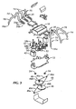
- Fig. 3 is an exploded perspective view the toy device of Fig. 1 having an outer housing and a projectile launcher removed;
- Fig. 4 is an enlarged cross-sectional view of the toy device of Fig. 1 taken generally along line 4-4 of Fig. 2 , the toy device having the outer housing and the projectile launcher removed;
- Fig. 5 is an enlarged cross-sectional view of the toy device of Fig. 1 taken generally along line 5-5 of Fig. 2 , the toy device having the outer housing and the projectile launcher removed;
- Fig. 6 is a partial view of the toy device of Fig. 1 having an alternative drive mechanism and projectile launcher control;
- Fig. 7 is a side elevational view of the toy device of Fig. 6 .
- FIGs. 1-6 preferred embodiments of an articulated walking toy device, indicated generally at 10, configured for movement across a surface (not shown) in accordance with the present invention.
- the toy device 10 includes a frame 12 and a plurality of leg assemblies 14 movably coupled with the frame 12 so as to at least partially support the frame 12 for movement across the surface, as will be described in more detail below.
- Each leg assembly 14 includes a leg member 16.
- the toy device 10 includes six leg members 16, three leg members 16 on each opposing lateral side of a body or frame 12, to mimic an insect-like creature.
- the leg members 16 are preferably curved in order for a distal end of the leg members 16a to support the frame 12 above the surface and to give the device 10 an animal-like appearance.
- the leg members 16, toward the front and rear of the device 10, are preferably curved or angled toward the front or rear of the device 10 respectively, but it is within the scope of the present invention that the leg members 16 are identically shaped or have any shape capable of performing the desired movement. It is also within the scope of the present invention that there be more or less than six leg members 16, provided the toy device 10 can still function to propel or support and propel the toy device 10, as described herein.
- the toy device 10 is intended to have a power source, such as one or more batteries 18 (see Figs. 4 and 5 ) disposed within a battery case 20, for instance, to power movement of the toy device 10. Furthermore, it is preferred that the toy device 10 have control electronics (not shown) within a control electronics housing (not shown) and be remotely controlled by a user using a generally conventional remote control device (not shown) spaced from the toy device 10. Additionally, it is intended that the toy device 10 includes a decorative outer housing 22, which is decorated in a manner that is visually pleasing to the user, for instance, giving the toy device 10 a robotic, bug-like, and/or monster-like appearance.
- the toy device 10 preferably includes a generally conventional, spring actuated projectile launcher 24 engaged to a top surface of the outer housing 22.
- the projectile launcher 24 preferably uses conventional means to allow a single dart 26 to be selectively fired by a user
- the toy device 10 further includes wing-like, preferably stationary, structures 28 positioned on either side of the projectile launcher 24 to mimic wings or wing covers of an insect. While this is preferred, it is within the scope of the present invention that the projectile launcher 24 be configured differently so as to operate in a different, generally conventional manner and/or to fire more than one dart 26. It is also contemplated that the wing-like structures 28 of the toy device 10 be eliminated or differently configured.
- the projectile launcher 24 could be eliminated or replaced with a different device to perform a different function, such as a flashlight to illuminate an area around the toy device, a crane-like member to allow the user to pick up and move objects during play, or a canister for expelling a web-like substance, for instance.
- the plurality of leg members 16 are preferably attached to the frame 12 in a manner to allow the leg members 16 to move generally in at least two rotational directions, and, specifically, to pivot back and forth with respect to the frame 12 and to allow distal ends 16a of the leg members 30 to be raised and lowered with respect to the surface on which the toy device 10 is supported.
- the leg members 16 are arranged on first and second sides 22a, 22b of the device 10.
- the leg members 16 are configured to rotate with respect to the frame 12 about a joint 30 having at least two degrees of freedom.
- the joint 30 is preferably formed by a pin 32 passed through an hour glass shaped aperture 34 to provide rotational movement of the leg member 16 with respect to the frame 12 about at least first and second axes of rotation 36, 38 intersecting in the joint 30.
- the pin 32 is preferably fixed to or stationary with respect to the frame 12 however it is within the scope of the present invention that the pin 32 be attached to the joint 30 and rotatably retained within the frame 12 or between the frame 12 and the battery case 20.
- the shape of the aperture 34 allows rotation of the leg members 16 back and forth through interaction of the pin 32 with a narrow portion of the aperture 34 and pivoting of the leg members 16 upward and downward through interaction of the pin 32 with angled-out portions of the aperture 34.
- the aperture 34 has a central aperture axis 36' coaxial with the axis of rotation 36 of or about the pin 32.
- the aperture 34 is preferably disposed in a plane parallel with the central aperture axis 36' but the aperture 34 may also have an hour glass shape such that the aperture is formed about an axis of symmetry take about the central aperture axis 36'.
- the joint 30 provides rotational movement of the leg members 16 with respect to the frame 12 about at least first and second axes of rotation 36, 38 intersecting in the joint 30.
- the first axis 36 is coaxial with the longitudinal axis of the pin 32 and the second axes of rotation extends generally perpendicular to the first axis 36 shown into the page in Fig. 4 .
- leg members 16 be movably engaged with the frame 12 in a different manner, such as with a rotating hinge, a conventional universal joint or a ball-in-socket configuration (not shown), for instance, provided the leg members 16 are generally capable of moving in the at least two rotational directions, as described above.
- first and second motors 40, 42 which each drive a separate drive trains or mechanism 44.
- the drive mechanisms 44 are essentially identical, with the first motor 40 driving a first drive mechanism 44a and the second motor 42 driving a second drive mechanism 44b on the first and second lateral sides 22a, 22b of the device 10 respectively. Because the drive mechanisms 44a, 44b are essentially identical, only the first drive mechanism 44a will be described in detail.
- the first motor 40 drives a pulley 46 including a first (smaller) pulley wheel 46a and a second (larger) pulley wheel 46b, which are rotatably engaged to one another with a belt 46c.
- An output shaft 40a of the first motor 40 is rotatably fixed with the first pulley wheel 46a, such that actuation of the first motor 40 drives the first pulley wheel 46a to rotation and, in turn, rotates the second pulley wheel 46b.
- a drive gear 48 is fixed to the second pulley wheel 46b so as to rotate therewith.
- Three cranks 50 are disposed in a line proximate first lateral side 22a of the frame 12.
- the cranks 50 are preferably comprised of leg gears 50a.
- the drive gear 48 is meshed with two adjacent leg gears 50a of the three leg gears 50a engaged with the frame 12 to rotate the two meshed leg gears 50a about respective pins 52.
- An idler gear 54 is disposed between the third leg gear 50a and the leg gear 50a adjacent thereto. In this way, each of the leg gears 50a is driven in the same rotational direction by the first motor 40. Rotation of the leg gears 50a causes movement of the leg members 16, as described below.
- the first motor 40 controls operation of the leg members 16 on the first lateral side 22a of the toy device 10
- the second motor 42 similarly controls operation of the leg members 16 on the second lateral side 22b of the toy device 10, thereby allowing turning of the toy device 10 by actuating one of the first and second motors 40, 42 slower or in a direction opposite to the actuation of the other of the first and second motors 40, 42.
- the above-described drive train configuration is preferred, it is within the scope of the present invention that other drive train configurations be used, provided the alternate drive train configuration functions to cause similar movement of the leg members 16 of the toy device 10.
- a single motor and a drive train having a generally convention throw-out gear could be used for the movement of all six leg members 16.
- all leg members 16 move together in one direction (i.e., a forward walking motion of the toy device), and, when the motor is driven in a second direction, the leg members 16 on one lateral side of the toy device are caused to move in one direction (i.e., a rearward walking motion of the toy device), while the leg members on the other lateral side of the toy device, through operation of the throw-out gear, are caused to either move in an opposite direction (i.e., a forward walking motion of the toy device) or to stop motion, thereby allowing the toy device to be turned.
- each leg member 16 or smaller groups of leg members 16 could each have a separate motor and drive train.
- each leg member 16 includes a tab 56 extending therefrom and disposed generally within the toy device 10 proximate the respective crank 50.
- the tab 56 includes a ramped surface 56a with a slot 56b therealong.
- the ramped surface 56a is preferably angled with respect to the frame 12 such that the proximal end of the tab 56 is closest to the frame 12 and becomes further spaced from the frame 12 moving toward the joint 31.
- the slot 56b accepts an eccentric post 58 extending from a top surface of the respective crank 50.
- Rotation of the crank 50 causes revolution of the post 58 and causes movement of the leg member 16 in a front and back motion, or a direction generally parallel to the frame 12, due to interaction of the slot 56b with the post 58. Because the post 58 is eccentric with respect to the crank 50, quick return back-and-forth motion of the leg member 16 is produced such that the leg member 16 moves slower in one rotational direction (i.e., rearward with respect to the toy device 10 when the toy device 10 moves in a forward direction) than the opposite rotational direction (i.e., forward with respect to the toy device 10 when the toy device 10 moves in a forward direction).
- the post 58 includes upper cam surface 58a and the crank 50 includes a cam surface 58b, which essentially sandwich and capture the tab 56 of the leg member 16 therebetween to constrain the leg member 16 and control up and down motion of the leg member 16 or otherwise pivot about the second axis of rotation 38 of the joint 30.
- up and down motion of the leg member 16, motion perpendicular to the frame 12 can be controlled by the profile of the tab 34. That is, due to interaction of the ramped surface 34b of the tab 34 with the cam surfaces 58a, 50a of the post 58 and the crank 50 respectively, the leg member 16 is caused to pivot upwardly and downwardly during rotation of the crank 50.
- the shape of the ramped surface 56a is preferably tailored to cause the leg member 16 to be rotated in a first direction around the first axis of rotation 36 of the joint 30 during the cycle of movement than the leg member 16 is rotated in an opposing direction around the first axis of rotation 36 of the joint 30 during a remainder of the cycle of movement. In this way, the leg member 16 is moved in a cyclical walking motion during actuation of the first motor 40.
- the cranks 50 are configured so that the eccentric posts 58 are offset from one another to cause an offset of the cyclical motion of each of the leg members 16 from one another so that when some of the leg members 16 are in the quick return phase of motion and is out of contact with the surface, others of the leg members 16 are in the slower phase of motion and in contact with the surface to ensure that the toy device 10 remains supported on the surface by at least some of the leg members 16 during motion of the toy device 10.
- This offset further causes the toy device 10 to mimic an anatomic gait in order to approximate ambulation of an actual six-legged creature, like an insect.
- the toy device of Figs. 1-5 may include an alternate driving mechanism 144.
- Numbers similar to those used in Figs. 1-5 but incremented by one hundred indicate similar elements as discussed above but included in embodiment 10'. A discussion of the similar features has been eliminated for convenience only and is not limiting.
- Driving of the leg members 116 is preferably accomplished using first and second motors 140, 142, which each drive a separate drive trains or mechanism 144.
- the drive mechanisms 144 are essentially identical, with the first motor 140 driving a first drive mechanism 144a and the second motor 142 driving a second drive mechanism (not shown) on the first and second lateral sides 122a, 122b of the device 10' respectively. Because the drive mechanisms 144a are essentially identical, only the first drive mechanism 144a will be described in detail.
- the first motor 140 drives a gear train 146 including a first gear 146a, a second gear 146b and a third gear 146c, which are rotatably attached to the frame 112.
- the first gear 146a is meshed with the second gear 146b.
- the second gear 146b and the third gear 146c are preferably identical combination spur gears, each having a smaller inner gear portion 145 and a larger outer gear portion 147 but mounted with an opposite orientation such that the smaller inner gear portion 145 meshes with the larger outer gear portion 147 on each second and third gear 146b, 146c, respectively.
- the third gear 146c is operably connected through the frame 112 to a drive gear 148.
- the third gear 146c and the drive gear 148 are preferably fixedly coupled together through a common axel (not shown).
- the drive gear 148 drives the cranks 150, leg gears 150a and the idler gears 154 to move the leg members 116 as was described above.
- the drive mechanisms 144 and the corresponding components may be oriented directly underneath the frame 112 such that the orientation of the drive mechanisms 144 and tabs (not shown) is inverse to the orientation of the drive mechanisms 44 described above.
- the toy device 10 may include a latching mechanism 160 to releasably engage a dart 126 in a projectile launcher 124.
- the latching mechanism 160 is spring biased from the projectile launcher 124 and includes two separately pivotably latch legs 160a and 160b.
- the latch legs 160a, 160b retain the dart 126 by engaging with a ridge 126a in the dart 126.
- First and second sector wheels 162a, 162b are rotatatably mounted on the top of the frame 112 and driven with the leg gear 150a positioned on the opposing side of the frame 112 such that the sector wheels 162a, 162b are driven in the same direction as the corresponding leg gears 150a.
- the sector wheels 162a, 162b have a circular flange 162c with an outer periphery notch 162d.
- a pair of levers 164 are pivotably mounted above each sector wheel 162. The levers 164 are positioned such that the extend through the notches 162d.
- the flanges 162c engage with the levers 164 to pivot the lever 164 in the direction of rotation.
- the sector wheels 162a, 162b rotate the corresponding levers 164 toward the latching mechanism 160 to pivot the latching mechanism 160 and releasing the latch legs 160a, 160b from the dart 126.
- both latch legs 160a, 160b must be released simultaneously in order to release the dart 126.
- the each drive mechanism 144 must be operated simultaneously in the same direction, again preferably corresponding to a reverse direction of the device 10'.
- each leg could be used to propel the toy device.
- Two legs also could be used to both support and propel the toy device.
- the distal, surface contacting end of each leg could be provided with a member or surface that resists rearward motion while permitting forward motion. This would permit each leg to be moved from a forward position to a rearward position as described above and brought back to a forward position without being raised from the support surface.
- each leg could be pivoted slightly downwardly at the end of its rearward movement to momentarily tilt the toy device away from that side before the leg is slightly raised from the surface and returned to a forward position.
- a chassis with support wheels or equivalents could be provided and the leg assemblies used only for propulsion.
- Four leg assemblies could be used to mimic four-legged creatures (e.g., mammals, amphibians, and reptiles) while eight leg assemblies can be used to mimic arachnids.
- the toy device can be factory preprogrammed to perform a predetermined movement or series of movements or configured to be selectively programmed by a user to create such predetermined movement(s).
- the toy device can be equipped with sensors, e.g., switches, proximity detectors, etc., that will control the toy device to turn away from or reverse itself automatically from whatever direction it was moving in if or when an obstacle is contacted or otherwise sensed.
Landscapes
- Toys (AREA)
Claims (11)
- Dispositif de jouet articulé qui marche (10) configuré pour se déplacer à travers une surface, le dispositif de jouet (10) comprenant :un châssis (12, 112)plusieurs ensembles de patte (14) reliés de manière mobile au châssis (12, 112) de manière à supporter au moins partiellement le châssis (12, 112) pour un déplacement à travers la surface, chaque ensemble de patte (14) comprenant un élément de patte (16) configuré pour tourner par rapport au châssis (12, 112) autour d'une articulation (30), une languette (56) s'étendant à partir de l'articulation (30) de manière générale en s'éloignant de l'élément de patte (16), une manivelle (50) reliée de manière opérationnelle à la languette (56) ; etun mécanisme d'entraînement (44, 144) en prise de manière opérationnelle avec les plusieurs ensembles de patte (14) de manière à actionner chacun des éléments de patte (16) parmi les plusieurs pour qu'il tourne autour de l'articulation (30) de manière analogue à un cycle de mouvement pouvant être répété, prédéterminé, au moins certains des éléments de patte (16) parmi les plusieurs étant déphasés par rapport à d'autres éléments de patte (16) des plusieurs pour produire comme une démarche anatomique du dispositif de jouet (10) sur la surface lors de l'actionnement du mécanisme d'entraînement (44, 144)caractérisé en ce quela languette (56) comprend une surface en rampe (56a) ayant une fente (56b) le long de celle-ci ; et en ce quela manivelle (50) est reliée de manière opérationnelle à la languette (56) pour coulisser le long de la fente (56b) de sorte qu'une rotation de la manivelle (50) amène l'élément de patte (16) à pivoter autour d'un premier axe de rotation (36) de l'articulation (30), la manivelle (50) ayant une surface de came (58b) reliée de manière opérationnelle à la surface en rampe (56a) de sorte qu'une rotation de la manivelle (50) amène la surface de came (58b) de la manivelle (50) à coulisser le long de la surface en rampe (56a) de la languette (56) et à faire pivoter l'élément de patte (16) autour d'un second axe de rotation (38) de l'articulation (30).
- Dispositif de jouet articulé qui marche selon la revendication 1, dans lequel l'articulation (30) est formée par un axe (32) passé à travers une ouverture en forme de sablier (34) pour fournir un mouvement de rotation de l'élément de patte (16) par rapport au châssis (12) autour des premier et second axes (36, 38) de rotation se recoupant dans l'articulation (30).
- Dispositif de jouet articulé qui marche selon la revendication 1, dans lequel une interaction de la manivelle (50) avec la fente (56b) provoque une rotation de l'élément de patte (16) dans une direction généralement parallèle à la surface supportant les plusieurs éléments de patte (16) et une interaction de la surface de came (58b) de la manivelle (50) avec la surface en rampe (56a) provoque une rotation de l'élément de patte (16) dans une direction généralement perpendiculaire à la surface supportant les plusieurs éléments de patte (16).
- Dispositif de jouet articulé qui marche selon la revendication 3 dans lequel la manivelle (50) est positionnée par rapport à la languette (56) et à l'articulation (30) de telle sorte que, pour chaque cycle de rotation de la manivelle (50), l'élément de patte relié (16) est mis en rotation plus vite dans une première direction autour du premier axe de rotation (36) de l'articulation (30) pendant le cycle de mouvement que l'élément de patte (16) n'est mis en rotation dans une direction opposée autour du premier axe de rotation (36) de l'articulation (30) pendant le reste du cycle de mouvement.
- Dispositif de jouet articulé qui marche selon la revendication 1 dans lequel le mécanisme d'entraînement (44) comprend :un premier moteur électrique (40) supporté par le châssis (12) ; etune roue de poulie (46) entraînée par le premier moteur électrique (40) et reliée de manière menante au moins aux ensembles de patte (14) disposés sur un premier côté latéral (22a) du dispositif.
- Dispositif de jouet articulé qui marche selon la revendication 5 dans lequel le mécanisme d'entraînement (44) comprend de plus :un second moteur électrique (42) supporté par le châssis (12) et relié de manière menante aux ensembles de patte (14) disposés sur un second côté latéral (22b) du dispositif opposé au premier côté latéral (22a) pour un mouvement des ensembles de patte (14) sur le second côté latéral (22b) indépendant du mouvement des ensembles de patte (14) du premier côté latéral (22a).
- Dispositif de jouet articulé qui marche selon la revendication 6 dans lequel la manivelle (50) de chaque ensemble de patte (14) est fournie par une roue dentée de patte (50a) montée pour tourner sur le châssis (12) et un montant (58) s'étendant transversalement par rapport à la roue dentée (50a) radialement espacé à partir d'un axe de rotation de la roue dentée de patte (50a), le montant (58) comprenant une surface de came (58a) reliée de manière opérationnelle à la surface en rampe (56a), chaque roue dentée de patte (50a) d'au moins les ensembles de patte (14) disposés sur le premier coté latéral du dispositif étant entraînée par la roue de poulie (46).
- Dispositif de jouet articulé qui marche selon la revendication 7 comprenant de plus une roue dentée d'entraînement (48) reliée de manière fixe à la roue de poulie (46) pour tourner avec la roue de poulie (46), la roue dentée d'entraînement (48) étant en prise de manière menante avec la roue dentée de patte (50a) d'un premier ensemble de patte (14) proximal par rapport à la poulie (46).
- Dispositif de jouet articulé qui marche selon la revendication 6, comprenant de plus une roue dentée de ralenti (54) entre chaque paire d'ensembles de patte adjacents (14) sur au moins le premier côté latéral (22a) du châssis (12) reliant de manière opérationnelle la paire d'ensembles de patte adjacents (14) pour un mouvement par mise en prise 90 simultanée avec la roue dentée de patte (50a) de chacun de la paire d'ensembles de patte adjacents (14), de sorte qu'un fonctionnement du premier moteur électrique (40) provoque une rotation de chaque roue dentée de patte (50a) de chacun des ensembles de patte (14) sur au moins le premier côté latéral (22a) du châssis (12) dans le même sens de rotation pour entraîner chacun des ensembles de patte (14) situés sur le premier côté latéral (22a) du châssis (12) dans les cycles de mouvement pouvant être répétés au même moment dans une même direction cyclique.
- Dispositif de jouet articulé qui marche selon la revendication 1, dans lequel le mécanisme d'entraînement (144) comprend :un premier moteur électrique (140) supporté par le châssis (112) relié de manière menante à une première roue de secteur (162a) ;un second moteur électrique (142) supporté par le châssis (112) relié de manière menante à une seconde roue de secteur (162b) ; etun mécanisme de verrouillage (160) relié de manière menante aux première et seconde roues de secteur (162a, 162b) et étant configuré pour libérer entièrement seulement lorsque le dispositif se déplace dans une de deux directions longitudinales.
- Dispositif de jouet articulé qui marche selon la revendication 1 comprenant de plus un lanceur de projectile actionné par ressort (24, 124) en prise sur une surface supérieure d'un boîtier extérieur (22).
Applications Claiming Priority (3)
| Application Number | Priority Date | Filing Date | Title |
|---|---|---|---|
| US79778106P | 2006-05-04 | 2006-05-04 | |
| US91571907P | 2007-05-03 | 2007-05-03 | |
| PCT/US2007/010991 WO2007130665A2 (fr) | 2006-05-04 | 2007-05-04 | Dispositif jouet articulé qui marche |
Publications (3)
| Publication Number | Publication Date |
|---|---|
| EP2012894A2 EP2012894A2 (fr) | 2009-01-14 |
| EP2012894A4 EP2012894A4 (fr) | 2011-10-19 |
| EP2012894B1 true EP2012894B1 (fr) | 2012-12-05 |
Family
ID=38668384
Family Applications (1)
| Application Number | Title | Priority Date | Filing Date |
|---|---|---|---|
| EP07776825A Not-in-force EP2012894B1 (fr) | 2006-05-04 | 2007-05-04 | Dispositif jouet articulé qui marche |
Country Status (4)
| Country | Link |
|---|---|
| EP (1) | EP2012894B1 (fr) |
| CA (1) | CA2651008C (fr) |
| MX (1) | MX2008014106A (fr) |
| WO (1) | WO2007130665A2 (fr) |
Families Citing this family (2)
| Publication number | Priority date | Publication date | Assignee | Title |
|---|---|---|---|---|
| CN102781529B (zh) * | 2010-01-06 | 2016-08-03 | M·兰德尔 | 用于产生步行运动的改进方法和设备 |
| DE102020007663A1 (de) | 2020-12-15 | 2022-06-15 | Edwin Wieschke | Spielzeugkäfer |
Family Cites Families (7)
| Publication number | Priority date | Publication date | Assignee | Title |
|---|---|---|---|---|
| US3331463A (en) * | 1964-12-14 | 1967-07-18 | Lyle L Kramer | Motor operated ambulatory vehicle |
| US4629440A (en) * | 1985-07-08 | 1986-12-16 | Mattel, Inc. | Animated toy |
| US4666419A (en) * | 1986-02-06 | 1987-05-19 | Coleco Industries, Inc. | Figure toy with gripping legs assembly |
| US5724954A (en) * | 1997-01-23 | 1998-03-10 | Hasbro, Inc. | Projectile launcher and cocking mechanism for same |
| DE10032640A1 (de) * | 2000-07-05 | 2002-01-17 | Jan Stein | Schreitroboter |
| US6527619B1 (en) * | 2001-10-31 | 2003-03-04 | Mattel, Inc. | Projectile firing toy vehicle |
| US6866557B2 (en) * | 2002-07-02 | 2005-03-15 | Mitch Randall | Apparatus and method for producing ambulatory motion |
-
2007
- 2007-05-04 MX MX2008014106A patent/MX2008014106A/es active IP Right Grant
- 2007-05-04 CA CA2651008A patent/CA2651008C/fr not_active Expired - Fee Related
- 2007-05-04 EP EP07776825A patent/EP2012894B1/fr not_active Not-in-force
- 2007-05-04 WO PCT/US2007/010991 patent/WO2007130665A2/fr not_active Ceased
Also Published As
| Publication number | Publication date |
|---|---|
| CA2651008A1 (fr) | 2007-11-15 |
| WO2007130665A2 (fr) | 2007-11-15 |
| WO2007130665A3 (fr) | 2008-11-13 |
| EP2012894A2 (fr) | 2009-01-14 |
| EP2012894A4 (fr) | 2011-10-19 |
| MX2008014106A (es) | 2008-11-14 |
| CA2651008C (fr) | 2012-07-03 |
Similar Documents
| Publication | Publication Date | Title |
|---|---|---|
| US7946902B2 (en) | Articulated walking toy | |
| US4629440A (en) | Animated toy | |
| CA1086943A (fr) | Robot articule (jouet) | |
| US3528193A (en) | Dismountable moving toy | |
| EP2012894B1 (fr) | Dispositif jouet articulé qui marche | |
| KR101267349B1 (ko) | 완구용 보행 로봇 | |
| CN214388884U (zh) | 一种动物玩具 | |
| US20060014470A1 (en) | Robot toy and drive device for toy | |
| US6165043A (en) | Four-legged walking toy with improved leg action | |
| JP2816671B2 (ja) | 歩走行機構及び該機構を備える歩走行ロボット | |
| EP1957174B1 (fr) | Jouet marcheur articule | |
| JPH076950Y2 (ja) | 戦闘人形 | |
| JPH0910442A (ja) | 形態変化玩具 | |
| JP3112670U (ja) | 玩具駆動モジュール | |
| KR900008770Y1 (ko) | 활동완구 | |
| JPH07289743A (ja) | 歩行動物玩具 | |
| KR20090007105U (ko) | 보행 완구 | |
| CN221933041U (zh) | 新型的旋转爬行玩具 | |
| CN214367579U (zh) | 运动切换联动机构和运动切换玩具 | |
| JPH0438878Y2 (fr) | ||
| JPH0223353Y2 (fr) | ||
| KR910004094Y1 (ko) | 완구의 입 개폐 장치 | |
| KR910000831Y1 (ko) | 동물 작동 완구 | |
| HK1121421B (en) | Articulated walking toy device | |
| SU184673A1 (ru) | Электромеханическая игрушка «штангист» |
Legal Events
| Date | Code | Title | Description |
|---|---|---|---|
| PUAI | Public reference made under article 153(3) epc to a published international application that has entered the european phase |
Free format text: ORIGINAL CODE: 0009012 |
|
| 17P | Request for examination filed |
Effective date: 20081112 |
|
| AK | Designated contracting states |
Kind code of ref document: A2 Designated state(s): AT BE BG CH CY CZ DE DK EE ES FI FR GB GR HU IE IS IT LI LT LU LV MC MT NL PL PT RO SE SI SK TR |
|
| AX | Request for extension of the european patent |
Extension state: AL BA HR MK RS |
|
| RIC1 | Information provided on ipc code assigned before grant |
Ipc: A63H 7/00 20060101AFI20090304BHEP |
|
| REG | Reference to a national code |
Ref country code: HK Ref legal event code: DE Ref document number: 1126999 Country of ref document: HK |
|
| DAX | Request for extension of the european patent (deleted) | ||
| A4 | Supplementary search report drawn up and despatched |
Effective date: 20110916 |
|
| RIC1 | Information provided on ipc code assigned before grant |
Ipc: A63H 11/20 20060101AFI20110912BHEP |
|
| REG | Reference to a national code |
Ref country code: DE Ref legal event code: R079 Ref document number: 602007027164 Country of ref document: DE Free format text: PREVIOUS MAIN CLASS: A63H0007020000 Ipc: A63H0011200000 |
|
| RIC1 | Information provided on ipc code assigned before grant |
Ipc: A63H 11/20 20060101AFI20120530BHEP |
|
| GRAP | Despatch of communication of intention to grant a patent |
Free format text: ORIGINAL CODE: EPIDOSNIGR1 |
|
| GRAS | Grant fee paid |
Free format text: ORIGINAL CODE: EPIDOSNIGR3 |
|
| GRAA | (expected) grant |
Free format text: ORIGINAL CODE: 0009210 |
|
| AK | Designated contracting states |
Kind code of ref document: B1 Designated state(s): AT BE BG CH CY CZ DE DK EE ES FI FR GB GR HU IE IS IT LI LT LU LV MC MT NL PL PT RO SE SI SK TR |
|
| REG | Reference to a national code |
Ref country code: GB Ref legal event code: FG4D |
|
| REG | Reference to a national code |
Ref country code: CH Ref legal event code: EP |
|
| REG | Reference to a national code |
Ref country code: AT Ref legal event code: REF Ref document number: 586938 Country of ref document: AT Kind code of ref document: T Effective date: 20121215 |
|
| REG | Reference to a national code |
Ref country code: IE Ref legal event code: FG4D |
|
| REG | Reference to a national code |
Ref country code: DE Ref legal event code: R096 Ref document number: 602007027164 Country of ref document: DE Effective date: 20130131 |
|
| REG | Reference to a national code |
Ref country code: AT Ref legal event code: MK05 Ref document number: 586938 Country of ref document: AT Kind code of ref document: T Effective date: 20121205 |
|
| PG25 | Lapsed in a contracting state [announced via postgrant information from national office to epo] |
Ref country code: SE Free format text: LAPSE BECAUSE OF FAILURE TO SUBMIT A TRANSLATION OF THE DESCRIPTION OR TO PAY THE FEE WITHIN THE PRESCRIBED TIME-LIMIT Effective date: 20121205 Ref country code: ES Free format text: LAPSE BECAUSE OF FAILURE TO SUBMIT A TRANSLATION OF THE DESCRIPTION OR TO PAY THE FEE WITHIN THE PRESCRIBED TIME-LIMIT Effective date: 20130316 Ref country code: FI Free format text: LAPSE BECAUSE OF FAILURE TO SUBMIT A TRANSLATION OF THE DESCRIPTION OR TO PAY THE FEE WITHIN THE PRESCRIBED TIME-LIMIT Effective date: 20121205 Ref country code: LT Free format text: LAPSE BECAUSE OF FAILURE TO SUBMIT A TRANSLATION OF THE DESCRIPTION OR TO PAY THE FEE WITHIN THE PRESCRIBED TIME-LIMIT Effective date: 20121205 |
|
| REG | Reference to a national code |
Ref country code: NL Ref legal event code: VDEP Effective date: 20121205 |
|
| REG | Reference to a national code |
Ref country code: LT Ref legal event code: MG4D |
|
| PG25 | Lapsed in a contracting state [announced via postgrant information from national office to epo] |
Ref country code: CY Free format text: LAPSE BECAUSE OF FAILURE TO SUBMIT A TRANSLATION OF THE DESCRIPTION OR TO PAY THE FEE WITHIN THE PRESCRIBED TIME-LIMIT Effective date: 20121205 Ref country code: GR Free format text: LAPSE BECAUSE OF FAILURE TO SUBMIT A TRANSLATION OF THE DESCRIPTION OR TO PAY THE FEE WITHIN THE PRESCRIBED TIME-LIMIT Effective date: 20130306 Ref country code: SI Free format text: LAPSE BECAUSE OF FAILURE TO SUBMIT A TRANSLATION OF THE DESCRIPTION OR TO PAY THE FEE WITHIN THE PRESCRIBED TIME-LIMIT Effective date: 20121205 Ref country code: PL Free format text: LAPSE BECAUSE OF FAILURE TO SUBMIT A TRANSLATION OF THE DESCRIPTION OR TO PAY THE FEE WITHIN THE PRESCRIBED TIME-LIMIT Effective date: 20121205 Ref country code: LV Free format text: LAPSE BECAUSE OF FAILURE TO SUBMIT A TRANSLATION OF THE DESCRIPTION OR TO PAY THE FEE WITHIN THE PRESCRIBED TIME-LIMIT Effective date: 20121205 |
|
| PG25 | Lapsed in a contracting state [announced via postgrant information from national office to epo] |
Ref country code: AT Free format text: LAPSE BECAUSE OF FAILURE TO SUBMIT A TRANSLATION OF THE DESCRIPTION OR TO PAY THE FEE WITHIN THE PRESCRIBED TIME-LIMIT Effective date: 20121205 |
|
| PG25 | Lapsed in a contracting state [announced via postgrant information from national office to epo] |
Ref country code: EE Free format text: LAPSE BECAUSE OF FAILURE TO SUBMIT A TRANSLATION OF THE DESCRIPTION OR TO PAY THE FEE WITHIN THE PRESCRIBED TIME-LIMIT Effective date: 20121205 Ref country code: SK Free format text: LAPSE BECAUSE OF FAILURE TO SUBMIT A TRANSLATION OF THE DESCRIPTION OR TO PAY THE FEE WITHIN THE PRESCRIBED TIME-LIMIT Effective date: 20121205 Ref country code: IS Free format text: LAPSE BECAUSE OF FAILURE TO SUBMIT A TRANSLATION OF THE DESCRIPTION OR TO PAY THE FEE WITHIN THE PRESCRIBED TIME-LIMIT Effective date: 20130405 Ref country code: BG Free format text: LAPSE BECAUSE OF FAILURE TO SUBMIT A TRANSLATION OF THE DESCRIPTION OR TO PAY THE FEE WITHIN THE PRESCRIBED TIME-LIMIT Effective date: 20130305 Ref country code: CZ Free format text: LAPSE BECAUSE OF FAILURE TO SUBMIT A TRANSLATION OF THE DESCRIPTION OR TO PAY THE FEE WITHIN THE PRESCRIBED TIME-LIMIT Effective date: 20121205 Ref country code: BE Free format text: LAPSE BECAUSE OF FAILURE TO SUBMIT A TRANSLATION OF THE DESCRIPTION OR TO PAY THE FEE WITHIN THE PRESCRIBED TIME-LIMIT Effective date: 20121205 |
|
| PG25 | Lapsed in a contracting state [announced via postgrant information from national office to epo] |
Ref country code: PT Free format text: LAPSE BECAUSE OF FAILURE TO SUBMIT A TRANSLATION OF THE DESCRIPTION OR TO PAY THE FEE WITHIN THE PRESCRIBED TIME-LIMIT Effective date: 20130405 Ref country code: RO Free format text: LAPSE BECAUSE OF FAILURE TO SUBMIT A TRANSLATION OF THE DESCRIPTION OR TO PAY THE FEE WITHIN THE PRESCRIBED TIME-LIMIT Effective date: 20121205 Ref country code: NL Free format text: LAPSE BECAUSE OF FAILURE TO SUBMIT A TRANSLATION OF THE DESCRIPTION OR TO PAY THE FEE WITHIN THE PRESCRIBED TIME-LIMIT Effective date: 20121205 |
|
| PLBE | No opposition filed within time limit |
Free format text: ORIGINAL CODE: 0009261 |
|
| STAA | Information on the status of an ep patent application or granted ep patent |
Free format text: STATUS: NO OPPOSITION FILED WITHIN TIME LIMIT |
|
| PG25 | Lapsed in a contracting state [announced via postgrant information from national office to epo] |
Ref country code: DK Free format text: LAPSE BECAUSE OF FAILURE TO SUBMIT A TRANSLATION OF THE DESCRIPTION OR TO PAY THE FEE WITHIN THE PRESCRIBED TIME-LIMIT Effective date: 20121205 |
|
| 26N | No opposition filed |
Effective date: 20130906 |
|
| PG25 | Lapsed in a contracting state [announced via postgrant information from national office to epo] |
Ref country code: IT Free format text: LAPSE BECAUSE OF FAILURE TO SUBMIT A TRANSLATION OF THE DESCRIPTION OR TO PAY THE FEE WITHIN THE PRESCRIBED TIME-LIMIT Effective date: 20121205 Ref country code: MC Free format text: LAPSE BECAUSE OF FAILURE TO SUBMIT A TRANSLATION OF THE DESCRIPTION OR TO PAY THE FEE WITHIN THE PRESCRIBED TIME-LIMIT Effective date: 20121205 |
|
| REG | Reference to a national code |
Ref country code: CH Ref legal event code: PL |
|
| REG | Reference to a national code |
Ref country code: DE Ref legal event code: R097 Ref document number: 602007027164 Country of ref document: DE Effective date: 20130906 |
|
| PG25 | Lapsed in a contracting state [announced via postgrant information from national office to epo] |
Ref country code: CH Free format text: LAPSE BECAUSE OF NON-PAYMENT OF DUE FEES Effective date: 20130531 Ref country code: LI Free format text: LAPSE BECAUSE OF NON-PAYMENT OF DUE FEES Effective date: 20130531 |
|
| REG | Reference to a national code |
Ref country code: IE Ref legal event code: MM4A |
|
| PG25 | Lapsed in a contracting state [announced via postgrant information from national office to epo] |
Ref country code: IE Free format text: LAPSE BECAUSE OF NON-PAYMENT OF DUE FEES Effective date: 20130504 |
|
| PGFP | Annual fee paid to national office [announced via postgrant information from national office to epo] |
Ref country code: GB Payment date: 20140527 Year of fee payment: 8 |
|
| PGFP | Annual fee paid to national office [announced via postgrant information from national office to epo] |
Ref country code: DE Payment date: 20140529 Year of fee payment: 8 Ref country code: FR Payment date: 20140519 Year of fee payment: 8 |
|
| PG25 | Lapsed in a contracting state [announced via postgrant information from national office to epo] |
Ref country code: MT Free format text: LAPSE BECAUSE OF FAILURE TO SUBMIT A TRANSLATION OF THE DESCRIPTION OR TO PAY THE FEE WITHIN THE PRESCRIBED TIME-LIMIT Effective date: 20121205 |
|
| REG | Reference to a national code |
Ref country code: DE Ref legal event code: R082 Ref document number: 602007027164 Country of ref document: DE Representative=s name: PATENTANWAELTE WEICKMANN & WEICKMANN, DE Ref country code: DE Ref legal event code: R082 Ref document number: 602007027164 Country of ref document: DE Representative=s name: WEICKMANN & WEICKMANN PATENTANWAELTE - RECHTSA, DE |
|
| PG25 | Lapsed in a contracting state [announced via postgrant information from national office to epo] |
Ref country code: TR Free format text: LAPSE BECAUSE OF FAILURE TO SUBMIT A TRANSLATION OF THE DESCRIPTION OR TO PAY THE FEE WITHIN THE PRESCRIBED TIME-LIMIT Effective date: 20121205 |
|
| PG25 | Lapsed in a contracting state [announced via postgrant information from national office to epo] |
Ref country code: HU Free format text: LAPSE BECAUSE OF FAILURE TO SUBMIT A TRANSLATION OF THE DESCRIPTION OR TO PAY THE FEE WITHIN THE PRESCRIBED TIME-LIMIT; INVALID AB INITIO Effective date: 20070504 Ref country code: LU Free format text: LAPSE BECAUSE OF NON-PAYMENT OF DUE FEES Effective date: 20130504 |
|
| REG | Reference to a national code |
Ref country code: HK Ref legal event code: WD Ref document number: 1126999 Country of ref document: HK |
|
| REG | Reference to a national code |
Ref country code: DE Ref legal event code: R119 Ref document number: 602007027164 Country of ref document: DE |
|
| GBPC | Gb: european patent ceased through non-payment of renewal fee |
Effective date: 20150504 |
|
| REG | Reference to a national code |
Ref country code: FR Ref legal event code: ST Effective date: 20160129 |
|
| PG25 | Lapsed in a contracting state [announced via postgrant information from national office to epo] |
Ref country code: DE Free format text: LAPSE BECAUSE OF NON-PAYMENT OF DUE FEES Effective date: 20151201 Ref country code: GB Free format text: LAPSE BECAUSE OF NON-PAYMENT OF DUE FEES Effective date: 20150504 |
|
| PG25 | Lapsed in a contracting state [announced via postgrant information from national office to epo] |
Ref country code: FR Free format text: LAPSE BECAUSE OF NON-PAYMENT OF DUE FEES Effective date: 20150601 |