EP2012488A1 - Receiver, method and corresponding computer program product for demodulating ALTBOC modulated signals - Google Patents
Receiver, method and corresponding computer program product for demodulating ALTBOC modulated signals Download PDFInfo
- Publication number
- EP2012488A1 EP2012488A1 EP20070425412 EP07425412A EP2012488A1 EP 2012488 A1 EP2012488 A1 EP 2012488A1 EP 20070425412 EP20070425412 EP 20070425412 EP 07425412 A EP07425412 A EP 07425412A EP 2012488 A1 EP2012488 A1 EP 2012488A1
- Authority
- EP
- European Patent Office
- Prior art keywords
- subcarrier
- signal
- signals
- altboc
- phase
- Prior art date
- Legal status (The legal status is an assumption and is not a legal conclusion. Google has not performed a legal analysis and makes no representation as to the accuracy of the status listed.)
- Granted
Links
Images


Classifications
-
- H—ELECTRICITY
- H04—ELECTRIC COMMUNICATION TECHNIQUE
- H04B—TRANSMISSION
- H04B1/00—Details of transmission systems, not covered by a single one of groups H04B3/00 - H04B13/00; Details of transmission systems not characterised by the medium used for transmission
- H04B1/69—Spread spectrum techniques
- H04B1/707—Spread spectrum techniques using direct sequence modulation
-
- G—PHYSICS
- G01—MEASURING; TESTING
- G01S—RADIO DIRECTION-FINDING; RADIO NAVIGATION; DETERMINING DISTANCE OR VELOCITY BY USE OF RADIO WAVES; LOCATING OR PRESENCE-DETECTING BY USE OF THE REFLECTION OR RERADIATION OF RADIO WAVES; ANALOGOUS ARRANGEMENTS USING OTHER WAVES
- G01S19/00—Satellite radio beacon positioning systems; Determining position, velocity or attitude using signals transmitted by such systems
- G01S19/01—Satellite radio beacon positioning systems transmitting time-stamped messages, e.g. GPS [Global Positioning System], GLONASS [Global Orbiting Navigation Satellite System] or GALILEO
- G01S19/13—Receivers
- G01S19/24—Acquisition or tracking or demodulation of signals transmitted by the system
- G01S19/29—Acquisition or tracking or demodulation of signals transmitted by the system carrier including Doppler, related
-
- G—PHYSICS
- G01—MEASURING; TESTING
- G01S—RADIO DIRECTION-FINDING; RADIO NAVIGATION; DETERMINING DISTANCE OR VELOCITY BY USE OF RADIO WAVES; LOCATING OR PRESENCE-DETECTING BY USE OF THE REFLECTION OR RERADIATION OF RADIO WAVES; ANALOGOUS ARRANGEMENTS USING OTHER WAVES
- G01S19/00—Satellite radio beacon positioning systems; Determining position, velocity or attitude using signals transmitted by such systems
- G01S19/01—Satellite radio beacon positioning systems transmitting time-stamped messages, e.g. GPS [Global Positioning System], GLONASS [Global Orbiting Navigation Satellite System] or GALILEO
- G01S19/13—Receivers
- G01S19/24—Acquisition or tracking or demodulation of signals transmitted by the system
- G01S19/30—Acquisition or tracking or demodulation of signals transmitted by the system code related
-
- H—ELECTRICITY
- H04—ELECTRIC COMMUNICATION TECHNIQUE
- H04B—TRANSMISSION
- H04B1/00—Details of transmission systems, not covered by a single one of groups H04B3/00 - H04B13/00; Details of transmission systems not characterised by the medium used for transmission
- H04B1/69—Spread spectrum techniques
- H04B1/707—Spread spectrum techniques using direct sequence modulation
- H04B1/7073—Synchronisation aspects
- H04B1/7085—Synchronisation aspects using a code tracking loop, e.g. a delay-locked loop
-
- H—ELECTRICITY
- H04—ELECTRIC COMMUNICATION TECHNIQUE
- H04L—TRANSMISSION OF DIGITAL INFORMATION, e.g. TELEGRAPHIC COMMUNICATION
- H04L27/00—Modulated-carrier systems
- H04L27/32—Carrier systems characterised by combinations of two or more of the types covered by groups H04L27/02, H04L27/10, H04L27/18 or H04L27/26
- H04L27/34—Amplitude- and phase-modulated carrier systems, e.g. quadrature-amplitude modulated carrier systems
- H04L27/36—Modulator circuits; Transmitter circuits
- H04L27/362—Modulation using more than one carrier, e.g. with quadrature carriers, separately amplitude modulated
- H04L27/363—Modulation using more than one carrier, e.g. with quadrature carriers, separately amplitude modulated using non - square modulating pulses, modulators specifically designed for this
-
- H—ELECTRICITY
- H04—ELECTRIC COMMUNICATION TECHNIQUE
- H04B—TRANSMISSION
- H04B2201/00—Indexing scheme relating to details of transmission systems not covered by a single group of H04B3/00 - H04B13/00
- H04B2201/69—Orthogonal indexing scheme relating to spread spectrum techniques in general
- H04B2201/707—Orthogonal indexing scheme relating to spread spectrum techniques in general relating to direct sequence modulation
- H04B2201/70715—Orthogonal indexing scheme relating to spread spectrum techniques in general relating to direct sequence modulation with application-specific features
Definitions
- the present invention relates to receivers of AltBOC (Alternated Binary Offset Carrier) modulated signals and to a method for demodulating AltBOC-modulated signals.
- AltBOC Alternated Binary Offset Carrier
- the present invention finds advantageous, but not exclusive, application in the field of global navigation satellite systems (GNSSs), to which the ensuing treatment will make explicit reference, without this implying any loss of generality.
- GNSSs global navigation satellite systems
- receivers used in global navigation satellite systems such as for example the global positioning system (GPS)
- GPS global positioning system
- the satellites forming part of the GPS constellation transmit signals using two carriers referred to as L1 and L2, wherein the carrier L1 has a frequency of 1575.42 MHz, whilst the carrier L2 has a frequency of 1227.60 MHz.
- Each carrier is modulated by at least one pseudorandom binary sequence (PRN), which consists in an apparently random sequence of ones and zeros that repeats periodically.
- PRN sequences are generally referred to with the term “code-chips”, whilst the transitions from one to zero and vice versa are generally referred to as “chip transitions”.
- PRN sequences are also referred to as "ranging codes”, since they enable estimation of the pseudoranges between receiver and satellite.
- Each GPS satellite uses a very precise PRN sequence of its own; for this reason, the GPS receiver can associate the signal received to the satellite that has emitted it by simply determining which PRN sequence is included in the signal.
- the GPS receiver calculates the difference between the instant in time in which the satellite has transmitted the signal, information contained in the signal itself, and the instant in time in which the receiver itself has received the signal. Basing on said temporal difference, the receiver calculates its own distance from the satellite, otherwise known as "pseudorange". Using the pseudoranges corresponding to at least four satellites, the receiver is able to calculate its own global position.
- the receiver synchronizes a PRN sequence generated locally with the PRN sequence present in the signal received. Said synchronization occurs by means of alignment of the code-chips present in each of the sequences. In this way, the GPS receiver determines the degree of temporal deviation of the locally generated PRN sequence with respect to the "GPS time", i.e., the time scale used by the satellite for generating its PRN sequence, and calculates the pseudorange.
- GPS time i.e., the time scale used by the satellite for generating its PRN sequence
- the operations of synchronization include the acquisition of the PRN sequence of the satellite and tracking thereof.
- the GPS receiver To acquire the PRN sequence, typically the GPS receiver makes a series of measurements of correlation at steps of half a code-chip; once the sequence has been acquired, the receiver tracks it.
- the receiver makes a series of "early-minus-late" measurements of correlation, namely, a series of measurements of the difference between (i) a measurement of correlation between a PRN sequence of the signal received and an anticipated version of the locally generated PRN sequence, and (ii) a measurement of correlation between the PRN sequence of the signal received and a delayed version of the locally generated PRN sequence.
- the GPS receiver uses the "early-minus-late" measurements in a delay-locked loop (DLL), which produces an error signal proportional to the misalignment between the local PRN sequence and the one received.
- DLL delay-locked loop
- Said error signal is used for controlling the generator of the local PRN sequence, which shifts the local PRN sequence in time so as to minimize the error signal coming from the DLL.
- the GPS receiver is also able to track the carrier used by the satellite for transmitting the PRN sequence and the navigation data.
- the GPS receiver uses a phase-locked loop (PLL).
- PLL phase-locked loop
- the carrier L1 is modulated by two PRN sequences referred to, respectively, as C/A code and P-code.
- the C/A code is a signal at 1.023 Mcps
- the P-code is a signal at 10.23 Mcps.
- the carrier L2 is modulated by just the P-code. Furthermore, both of the carriers (L1 and L2) are modulated also with the navigation message, transmitted at 50 bps with a BPSK modulation superimposed on the C/A and P codes: the navigation data are added with modulo-2 addition to the code-chips.
- a GPS receiver acquires the signal coming from a satellite using a locally generated copy of the C/A code, as well as a locally generated carrier L1.
- the receiver After acquisition, in the tracking step, the receiver synchronizes the local C/A code and the carrier L1 with the C/A code and the carrier L1 of the signal received from the satellite, using appropriate correlators in the DLL and in the PLL. The receiver can subsequently use the information corresponding to tracking of the C/A code for tracking of the P-code in L1 band and/or L2 band, since the temporal relations between said signals are known.
- Galileo The European Commission and the European Space Agency are developing a new GNSS, known as Galileo, which aims at enabling location of the users with a precision such as to guarantee different types of services.
- said services can be divided into:
- the Galileo system avails itself, not only of appropriate infrastructures on the ground, but also of a constellation of satellites, each of which emits appropriate signals characterized by pseudorandom sequences associated uniquely to the satellite itself, so that the receiver of the user can associate each signal received to the satellite that has emitted it, as occurs in GPS.
- the satellites of the Galileo system will transmit signals, modulating three separate carriers, referred to as E5, E6 and E2-L1-E1 (also known, for reasons of brevity, as L1).
- E5 the band used for the services of air radionavigation
- RNSS the band allocated for the services of satellite radionavigation
- SAR is the band assigned to the search-and-rescue service of the Galileo system.
- the satellites of the Galileo constellation transmit the signals in the E5a sub-band (central frequency equal to 1176.45 MHz) and in the E5b sub-band (central frequency equal to 1207.14 MHz) in the form of a composite signal s E5 (t) having a central frequency of 1191.795 MHz, using the modulation format generally known as "Alternative Binary Offset Carrier" (AltBOC).
- AltBOC Alternative Binary Offset Carrier
- the signal s E5 (t) as a function of four signals, namely e E5a-I (t), e E5a-Q (t), e E5b-I (t) and e E5b-Q (t).
- Two of these signals, e E5a-I (t) and e E5b-I (t) contain navigation data and spreading codes, whilst the other two signals, e E5a-Q (t) and e E5b-Q (t), are pilot channels that do not contain data.
- the subscripts I and Q designate two signals that are in quadrature with respect to one another, the meaning of which will be clarified in what follows.
- FIG. 2 Illustrated in Figure 2 is a block diagram representing the generation of the signal s E5 (t) according to the four signals e E5a-I (t), e E5a-Q (t), e E5b-I (t) and e E5b-Q (t), in which the latter are represented by means of the binary flows of the corresponding spreading codes, designated, respectively, by C E5a-I (t), C E5a-Q (t), C E5b-I (t) and C E5b-Q (t), and by means of the binary flows of the corresponding navigation data, designated, respectively, by D E5a-I (t) and D E5b-I (t).
- the data flows are distinguished into freely accessible navigation messages (Open Service, also referred to as F/NAV) and integrity messages (Safety of Life, also referred to as I/NAV).
- Open Service also referred to as F/NAV
- I/NAV integrity messages
- rect T ( t ) is a boxcar function, which is equal to 1 in the interval 0 ⁇ t ⁇ T and zero elsewhere.
- the signal e E5a-Q (t) is instead a pilot channel and consequently contains just the information associated to the ranging code C E5a-Q :
- the signals e E5a-I (t), e E5a-Q (t), e E5b-I (t) and e E5b-Q (t) are modulated together in just the signal s E5 (t) thanks to the Alternative Binary Offset Carrier (AltBOC) modulation.
- AltBOC Alternative Binary Offset Carrier
- the generation of said AltBOC-modulated signal in the E5 band (1164-1215 MHz) is described in the aforesaid manual Gal OS SIS ICD.
- the AltBOC-modulation format consists in a variant of the "Binary Offset Carrier" (BOC) format, which envisages modulation of the signal in the time domain by means of a square wave sign[sin(2 ⁇ f s t)], which causes a displacement of the spectrum of the signal in a higher band and in a corresponding lower band.
- BOC Binary Offset Carrier
- Said modulation format is generally known as BOC( f s , f c ), wherein f s is the frequency of the subcarrier (square wave), whilst f c is the chip frequency of the pseudorandom sequence (code-chip rate).
- said frequencies are normalized with respect to a reference frequency of 1.023 MHz; i.e., they are expressed as multiples of said reference frequency and designated, respectively, by m and n.
- the BOC-modulation format (15.345 MHz, 10.23 Mcps), for example, is usually expressed as BOC(15,10).
- s BOC x t ⁇ sign sin 2 ⁇ ⁇ ⁇ f s ⁇ t
- x(t) is a generic base-band signal of a BPSK (Binary Phase Shift Keying) type, which contains the data that are to be transmitted.
- the power spectral density S BOC (f) of the modulated signal can be expressed, neglecting the higher-order harmonics, as: s BOC ⁇ ⁇ ⁇ X ⁇ f - f s - ⁇ ⁇ X ⁇ f + f s wherein X(f) is the power spectral density of x(t).
- the signal e(t) is a signal BPSK-modulated with a pseudorandom sequence having a chip rate R C , and possibly also with navigation data having a symbol rate R D lower than the chip rate (R D ⁇ R C ) .
- the BOC-modulation format produces signals having a frequency spectrum divided into two adjacent side frequency bands. Said two side bands of the spectrum contain the same information. In this way, it is possible to transmit the navigation data multiplied by a pseudorandom sequence (PRN) on said two side bands.
- PRN pseudorandom sequence
- the spectra of the signals er(t) and er*(t) are each constituted by a main line, respectively, at frequency ⁇ f s , and by other lower harmonics spaced by 4 f s .
- an AltBOC(15,10) modulation is used, i.e., with square subcarrier at 15.345 MHz, formed by four BPSK signals with chip rate equal to 10.23 Mchip / s, of which two contain navigation data and two are pilot channels.
- the spectral occupation of the signal E5 is given in Figure 4 .
- the signals e E5a-I ( t ), e E5a-Q (t) , e E5b-I ( t) and e E5b-Q (t) are precisely the signals described in Eqs. (12-15) and are BPSK-modulated.
- the coefficients AS i and AP i are defined in Table 2 illustrated in Figure 12 .
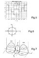
- a period of the functions sc E5-S (t) and SC E5-P (t) is given in Figure 5 , wherein the former is represented with a solid line, whilst the latter is represented with a dashed line.
- the signal sc E5-S ( t-T S,E5 /4) present in Eq. (16) will be designated in what follows by sc E ⁇ 5 - S off t .
- AltBOC modulation enables use of the E5 band as two separate side bands, which are known as E5a band (1164-1191.795 MHz) and E5b band (1191.795-1215 MHz).
- E5a band (1164-1191.795 MHz)
- E5b band 1191.795-1215 MHz.
- a single data channel equivalent to a BPSK-modulated signal
- a pilot channel i.e., another BPSK-modulated signal
- the AltBOC-modulation scheme can also be viewed as the combination of two separate QPSK (Quadrature Phase Shift Keying) modulations, centred, respectively, at the central frequencies of the E5a and E5b bands.
- QPSK Quadrature Phase Shift Keying
- Demodulating the navigation data contained in the signal received is consequently complicated by the fact that the two channels e E5a-I ( t ) and e E5b-I ( t ) are transmitted in different side bands.
- the patent application WO2006/027004 describes a method for demodulating AltBOC-modulated signals comprising at least two subcarriers each having an in-phase component and a quadrature component modulated by pseudorandom codes.
- the quadrature components are modulated by pilot signals which do not carry data, whilst the in-phase components are modulated by signals containing data.
- the demodulation method envisages conversion of the AltBOC-modulated signal at intermediate frequency, pass-band filtering of the converted signals, sampling of the filtered signals, generation of a phase of the carrier, rotation of the phase of the carrier of the sampled signals via said phase of the carrier, correlation of the sampled and rotated signals, and generation, for each subcarrier, of pseudorandom binary codes and a phase of the subcarrier, which are used for correlating the signals sampled and rotated.
- the receiver eliminates the complex signal from the signal received by multiplying the latter, the in-phase and quadrature components of which have been translated into base-band, by the complex signal generated locally.
- the receiver uses the results, which are correlated to the in-phase and quadrature components, for estimating the tracking error of the carrier phase.
- the error signal is then used for controlling in a known way a numeric-control oscillator, for correcting the phase of the locally generated carrier.
- the receiver also uses anticipated and delayed versions of the complex pilot signal generated locally in a DLL, and aligns the locally generated complex pilot signal with the complex pilot signal received, minimizing the corresponding error signal of the DLL.
- the receiver determines its pseudorange and the global position in a known way.
- the receiver moreover uses a distinct set of correlators to align locally generated versions of the PRN sequences in phase with the PRN sequences of the in-phase channel present in the signal received, thus recovering the transmitted data.
- the true AltBOC-modulated signal that will be used in the Galileo system differs from the signals Complex-LOC and Complex-BOC on account of the presence of additional terms, the so-called product signals defined in Eqs. (17-20), and on account of the different shape of the subcarriers sc E5-S ( t ) and sc E5-P ( t ), so that the performance obtained is not optimal.
- the technique proposed does not enable demodulating just one data channel, as it might be useful to do, for example, in situations in which the navigation data of the other data channel are not necessary.
- the aim of the present invention is to provide a receiver of AltBOC-modulated signals and a method for demodulating said signals that will enable the drawbacks of the known art to be overcome at least in part.
- the above aim is achieved by the present invention in so far as it relates to a receiver of AltBOC-modulated signals, to a method for demodulating AltBOC-modulated signals, and to a corresponding computer program product, as defined in the annexed claims.
- an AltBOC-modulated signal may be decomposed into four BPSK-modulated in-phase and quadrature signals around two distinct frequencies in two adjacent bands.
- the present invention enables extraction of the in-phase components e E5a-I (t) and e E5b-I (t) implementing a technique of frequency translation forming the subject of the present invention, which in what follows will be referred to for reasons of brevity as "Side-Band Translation" (SBT).
- SBT Segment-Band Translation
- the translation of the spectrum of the signal received is performed by multiplying the signal received by complex exponentials, whilst the selection of the in-phase signals e E5a-I (t) and e E5b-I (t) is performed by extracting only the real parts of the signals translated in frequency.
- the base-band translation of the spectrum of the signal received is performed by multiplying the signal received by real signals, and in particular local replicas of the signal sc E5-S (t) defined in Eq. (21), subcarrier of the AltBOC-modulated signal.
- the selection of the in-phase signals e E5a-I (t) and e E5b-I (t) is instead performed in a traditional way by extracting the real part of the translated signals.
- the in-phase signals e E5a-I (t) and e E5b-I (t) thus extracted are subjected to operations of despreading and BPSK demodulation performed according to the known art, thus recovering the navigation data.
- the present invention guarantees better performance in reception, greater resilience to interference, as well as a high flexibility of use.
- the SBT technique according to the present invention envisages making two separate translations in frequency, one for each side band of the spectrum of the AltBOC-modulated signal received and, subsequently, selection of the correct channels, namely, just the in-phase channels, containing the navigation data.
- Figure 8 shows a theoretical block diagram of the technique of extraction of the in-phase components e E5a-I ( t ) and e E5b-I ( t ) of the received AltBOC-modulated signal s E5 ( t ) according to the present invention.
- This operation of multiplication of the received signal by a subcarrier causes a base-band translation from the side bands of the spectrum of the received AltBOC-modulated signal.
- the two output signals s 1 ( t ) and s 2 ( t ) are then supplied at input to a first block for extracting the real part Re 1 and, respectively, a second block for extracting the real part Re 2 , which supply at output the in-phase components e E5a-I (t) and e E5b-I (t).
- the first exponential subcarrier is represented by the term sc E ⁇ 5 - S t - j ⁇ sc E ⁇ 5 - S off t , which implements an operation of frequency translation similar to the one performed by the complex exponential e -j ⁇ 2 ⁇ f sub t of Figure 8 , and, in the case of AltBOC(15,10) modulation, said translation is 15.345 MHz.
- This multiplication by a subcarrier causes a translation downwards of the frequency spectrum of the two channels in E5a band: the signals e E5a-I (t) and e E5a-Q (t) are translated from the base band to the left sub-band of the spectrum of the AltBOC-modulated E5 signal.
- the second exponential subcarrier is represented by the term sc E ⁇ 5 - S t + j ⁇ sc E ⁇ 5 - S off t , which implements an operation of frequency translation similar to the one performed by the complex exponential e +j ⁇ 2 ⁇ f sub t of Figure 8 .
- This multiplication by a subcarrier causes a translation in frequency of the two ???channels ???signals e E5b-I (t) and e E5b-Q (t) in the E5b band.
- Eqs. (30) and (33) define the operation of the SBT technique according to the present invention and enable a simple recovery of the in-phase components e E5a-I (t) and e E5b-I (t) .
- Figure 9 shows a block diagram of implementation of the SBT technique, in which the operations described by Eqs. (30) and (33) are implemented directly in the discrete-time domain, by means of multiplications and sums between samples of the signal received and waveforms of the locally generated subcarriers.
- FIG. 9 designated as a whole by 1 in Figure 9 is a block for extracting the in-phase components e E5a-I (t) and e E5b- I (t) of the AltBOC-modulated signal received s E5 (t) .
- the extractor block 1 comprises a frequency-translator stage 2 implementing the SBT technique according to the present invention, followed by an extractor stage 3 proper.
- the frequency-translator stage 2 comprises a first multiplier 4 and a second multiplier 5, which receive at input, respectively, the in-phase and quadrature components s E5I (t) and s E5Q (t) of the AltBOC-modulated signal received s E5 (t), which are recovered by the receiver in a known way and hence not described in detail.
- This operation of multiplication of the in-phase and quadrature components s E5I ( t ) and s E5Q ( t ) of the AltBOC-modulated signal received s E5 ( t ) by the two signals sc E5-S ( t ) and sc E ⁇ 5 - S off t causes a base-band translation from the side bands of the spectrum of the AltBOC-modulated signal received.
- the form and bandwidth of the filters must be optimized so as to achieve a compromise between the performance of the demodulation section and the reduction in the interference and the cross-correlation with the adjacent channels: in fact, an excessively narrow filtering reduces the performance of the demodulation section, worsening the properties of correlation of the two data channels, but an excessively wide filtering may prove disadvantageous in the presence of noise and interference.
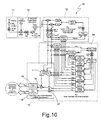
- Figure 10 represents a high-level block diagram of the architecture of a receiver of AltBOC-modulated signals implementing the SBT technique according to the present invention.
- the details of implementation regarding the operations of complex correlation and discrimination, in addition to possible optimizations of the architecture itself of the receiver, are not given herein, in so far as they belong to the known art.
- the receiver designated as a whole by 10, comprises a radiofrequency (RF) stage 11, an intermediate-frequency (IF) stage 12, a phase-locked loop (PLL) 13, a delay-locked loop (DLL) 14, and a demodulation stage 15, which in turn comprises the extractor block 1 of Figure 9 , two multipliers 16 and 17 designed to carry out despreading of the PRN sequences, and two BPSK demodulators 18 and 19 designed to demodulate the data.
- RF radiofrequency
- IF intermediate-frequency
- PLL phase-locked loop
- DLL delay-locked loop
Abstract
Description
- The present invention relates to receivers of AltBOC (Alternated Binary Offset Carrier) modulated signals and to a method for demodulating AltBOC-modulated signals.
- The present invention finds advantageous, but not exclusive, application in the field of global navigation satellite systems (GNSSs), to which the ensuing treatment will make explicit reference, without this implying any loss of generality.
- As is known, receivers used in global navigation satellite systems, such as for example the global positioning system (GPS), determine their global position basing on the signals received from satellites forming part of a GPS constellation or the like.
- For example, the satellites forming part of the GPS constellation transmit signals using two carriers referred to as L1 and L2, wherein the carrier L1 has a frequency of 1575.42 MHz, whilst the carrier L2 has a frequency of 1227.60 MHz.
- Each carrier is modulated by at least one pseudorandom binary sequence (PRN), which consists in an apparently random sequence of ones and zeros that repeats periodically. The ones and zeros present in the PRN sequence are generally referred to with the term "code-chips", whilst the transitions from one to zero and vice versa are generally referred to as "chip transitions". Technically, PRN sequences are also referred to as "ranging codes", since they enable estimation of the pseudoranges between receiver and satellite.
- Each GPS satellite uses a very precise PRN sequence of its own; for this reason, the GPS receiver can associate the signal received to the satellite that has emitted it by simply determining which PRN sequence is included in the signal.
- The GPS receiver calculates the difference between the instant in time in which the satellite has transmitted the signal, information contained in the signal itself, and the instant in time in which the receiver itself has received the signal. Basing on said temporal difference, the receiver calculates its own distance from the satellite, otherwise known as "pseudorange". Using the pseudoranges corresponding to at least four satellites, the receiver is able to calculate its own global position.
- To determine the temporal difference between the instant in time in which the satellite transmits the signal and the instant in which the receiver receives it, the receiver synchronizes a PRN sequence generated locally with the PRN sequence present in the signal received. Said synchronization occurs by means of alignment of the code-chips present in each of the sequences. In this way, the GPS receiver determines the degree of temporal deviation of the locally generated PRN sequence with respect to the "GPS time", i.e., the time scale used by the satellite for generating its PRN sequence, and calculates the pseudorange.
- The more precisely the GPS receiver aligns the locally generated PRN sequence with the PRN sequence present within the signal received, the more precisely the GPS receiver can determine the temporal deviation between said sequences, the pseudoranges and, consequently, its own global position.
- The operations of synchronization include the acquisition of the PRN sequence of the satellite and tracking thereof. To acquire the PRN sequence, typically the GPS receiver makes a series of measurements of correlation at steps of half a code-chip; once the sequence has been acquired, the receiver tracks it.
- In general, to carry out synchronization, the receiver makes a series of "early-minus-late" measurements of correlation, namely, a series of measurements of the difference between (i) a measurement of correlation between a PRN sequence of the signal received and an anticipated version of the locally generated PRN sequence, and (ii) a measurement of correlation between the PRN sequence of the signal received and a delayed version of the locally generated PRN sequence.
- Subsequently, the GPS receiver uses the "early-minus-late" measurements in a delay-locked loop (DLL), which produces an error signal proportional to the misalignment between the local PRN sequence and the one received. Said error signal is used for controlling the generator of the local PRN sequence, which shifts the local PRN sequence in time so as to minimize the error signal coming from the DLL.
- In addition to this, typically the GPS receiver is also able to track the carrier used by the satellite for transmitting the PRN sequence and the navigation data. To do this, the GPS receiver uses a phase-locked loop (PLL).
- In the specific case of GPS, the carrier L1 is modulated by two PRN sequences referred to, respectively, as C/A code and P-code. The C/A code is a signal at 1.023 Mcps, whilst the P-code is a signal at 10.23 Mcps.
- The carrier L2 is modulated by just the P-code. Furthermore, both of the carriers (L1 and L2) are modulated also with the navigation message, transmitted at 50 bps with a BPSK modulation superimposed on the C/A and P codes: the navigation data are added with modulo-2 addition to the code-chips.
- Generally, a GPS receiver acquires the signal coming from a satellite using a locally generated copy of the C/A code, as well as a locally generated carrier L1.
- After acquisition, in the tracking step, the receiver synchronizes the local C/A code and the carrier L1 with the C/A code and the carrier L1 of the signal received from the satellite, using appropriate correlators in the DLL and in the PLL. The receiver can subsequently use the information corresponding to tracking of the C/A code for tracking of the P-code in L1 band and/or L2 band, since the temporal relations between said signals are known.
- The European Commission and the European Space Agency are developing a new GNSS, known as Galileo, which aims at enabling location of the users with a precision such as to guarantee different types of services. In particular, said services can be divided into:
- free basic service, called Open Service (OS), for applications and services of general interest; unlike the GPS, said service will offer a higher quality and reliability;
- a commercial service (CS), aimed at development of added-value services and professional applications that will offer potentiated performance with respect to the basic service, especially in terms of guarantee of service;
- a "vital" service, known as Safety Of Life Service (SOL), which is able to provide guarantees as regards integrity of the Galileo system for applications concerning human life, such as air or marine navigation;
- a search-and-rescue service (SAR) aimed at improving the systems of assistance in the case of emergency search and rescue; and
- a government service, called Public Regulated Service (PRS), encrypted and resistant to blacking-out and interference, reserved to the needs of public institutions. The signals and codes corresponding to PRS are not available to the public.
- In order to guarantee the services referred to, characterized by different levels of precision required, the Galileo system avails itself, not only of appropriate infrastructures on the ground, but also of a constellation of satellites, each of which emits appropriate signals characterized by pseudorandom sequences associated uniquely to the satellite itself, so that the receiver of the user can associate each signal received to the satellite that has emitted it, as occurs in GPS.
- The satellites of the Galileo system will transmit signals, modulating three separate carriers, referred to as E5, E6 and E2-L1-E1 (also known, for reasons of brevity, as L1). The frequencies of said carriers, as well as the respective band occupations of the modulated signals are given in
Figure 1 , in which ARNS is the band used for the services of air radionavigation, RNSS is the band allocated for the services of satellite radionavigation, and SAR is the band assigned to the search-and-rescue service of the Galileo system. - As far as the signals transmitted in the bands E5, E6, L1 are concerned, there should be mentioned:
- the E1 signal: this is a freely accessible signal transmitted in the band L1 and comprising a data channel, i.e., a signal that contains within it also navigation data, referred to as E1-B, and a pilot channel, i.e., a signal that does not contain data, referred to as E1-C. The ranging codes of the E1 signal are not encrypted, and the navigation data are accessible to all users. The data flow E1-B also contains non-encrypted integrity messages and encrypted commercial data; the data rate of said E1 signal-B is 125 bps. The E1 signal supports OS, CS and SOL services;
- the E6 signal: this is a commercial signal transmitted in the E6 band; it includes a data channel referred to as E6-B and a pilot channel E6-C. Its ranging codes and data are encrypted. The data rate is 500 bps and enables transmission of commercial data for added-value services. The E6 signal is dedicated for CS services;
- the E5a signal: this is a signal freely accessible to users transmitted in the E5 band; it includes a data channel and a pilot channel. The ranging codes of the E5a signal are not encrypted, and the navigation data are accessible to all users. It transmits the basic data supporting navigation and timing, making use of a data rate of 25 bps, designed to guarantee a robust demodulation. The signal E5 supports OS services; and
- the E5b signal: this is a signal freely accessible to users transmitted in the E5 band; it includes a data channel and a pilot channel. The ranging codes of the E5b signal and the navigation data are accessible to all users. The data flow of the channel E5b contains non-encrypted integrity messages and encrypted commercial data. The data rate is 125 bps. The E5b signal supports OS, CS and SOL services.
- For greater detail regarding the use of the bands in the Galileo system, as well as for all the information regarding encoding of the signals used, the reader is referred to the publicly available manual "Galileo Open Service Signal In Space Interface Control Document", for reasons of brevity defined hereinafter as "Galileo OS SIS ICD", 2006, European Space Agency / Galileo Joint Undertaking, which can be consulted on the site:
http://www.galitleoic.org/la/files/Galileo%20OS%20SIS%20ICD%202 30506.pdf.
Exactly as in the case of GPS, the receiver receives the signal and calculates its own pseudoranges basing on the difference between the instant in time in which the satellite has transmitted the signal and the instant in time in which the receiver receives the signal. - As far as the E5 band in particular is concerned, the satellites of the Galileo constellation transmit the signals in the E5a sub-band (central frequency equal to 1176.45 MHz) and in the E5b sub-band (central frequency equal to 1207.14 MHz) in the form of a composite signal sE5(t) having a central frequency of 1191.795 MHz, using the modulation format generally known as "Alternative Binary Offset Carrier" (AltBOC). For a more detailed treatment of this format, reference may be made to the aforesaid manual Galileo OS SIS ICD.
- From the standpoint of the binary flow of the data, it is possible to imagine the signal sE5(t) as a function of four signals, namely eE5a-I(t), eE5a-Q(t), eE5b-I(t) and eE5b-Q(t). Two of these signals, eE5a-I(t) and eE5b-I(t), contain navigation data and spreading codes, whilst the other two signals, eE5a-Q(t) and eE5b-Q(t), are pilot channels that do not contain data. The subscripts I and Q designate two signals that are in quadrature with respect to one another, the meaning of which will be clarified in what follows.
- Illustrated in
Figure 2 is a block diagram representing the generation of the signal sE5(t) according to the four signals eE5a-I(t), eE5a-Q(t), eE5b-I(t) and eE5b-Q(t), in which the latter are represented by means of the binary flows of the corresponding spreading codes, designated, respectively, by CE5a-I(t), CE5a-Q (t), CE5b-I (t) and CE5b-Q (t), and by means of the binary flows of the corresponding navigation data, designated, respectively, by DE5a-I(t) and DE5b-I(t). InFigure 2 , moreover, the data flows are distinguished into freely accessible navigation messages (Open Service, also referred to as F/NAV) and integrity messages (Safety of Life, also referred to as I/NAV). - In greater detail, the signal eE5a-I(t) can be written as a combination of the navigation data DE5a-I with the ranging code CE5a-I :

wherein rect T (t) is a boxcar function, which is equal to 1 in theinterval 0<t<T and zero elsewhere. For the meaning of the symbols used in Eq. (1) and in the subsequent ones, see the table presented inFigure 11 . - The signal eE5a-Q (t) is instead a pilot channel and consequently contains just the information associated to the ranging code CE5a-Q:

- The signal eE5b-I(t) is given by the combination of the navigation data DE5b-I with the ranging code CE5b-I :

- Finally, the signal eE5b-Q(t) is a pilot channel, present in which is simply the ranging code CE5b-Q :

- The signals eE5a-I(t), eE5a-Q(t), eE5b-I(t) and eE5b-Q(t) are modulated together in just the signal sE5(t) thanks to the Alternative Binary Offset Carrier (AltBOC) modulation. The generation of said AltBOC-modulated signal in the E5 band (1164-1215 MHz) is described in the aforesaid manual Gal OS SIS ICD.
- The AltBOC-modulation format consists in a variant of the "Binary Offset Carrier" (BOC) format, which envisages modulation of the signal in the time domain by means of a square wave sign[sin(2πfst)], which causes a displacement of the spectrum of the signal in a higher band and in a corresponding lower band.
- Said modulation format is generally known as BOC(fs ,f c), wherein fs is the frequency of the subcarrier (square wave), whilst fc is the chip frequency of the pseudorandom sequence (code-chip rate). Generally, said frequencies are normalized with respect to a reference frequency of 1.023 MHz; i.e., they are expressed as multiples of said reference frequency and designated, respectively, by m and n. For this reason, the BOC-modulation format (15.345 MHz, 10.23 Mcps), for example, is usually expressed as BOC(15,10).
- It is possible to express the signal BOC(fs,fc ) in the form:

wherein x(t) is a generic base-band signal of a BPSK (Binary Phase Shift Keying) type, which contains the data that are to be transmitted. - The power spectral density SBOC(f) of the modulated signal can be expressed, neglecting the higher-order harmonics, as:

wherein X(f) is the power spectral density of x(t). - There is thus obtained to a good approximation the division on the spectrum into two components symmetrical with respect to a central frequency, as represented in
Figure 3 , in which a comparison is given between the spectra of the BOC and BPSK modulations. In particular, inFigure 3 represented with a solid line is the spectral occupation of the P-code, indicated with a dashed line is the spectral occupation of the C/A code, indicated with a dashed-and-dotted line is the spectral occupation of a BOC(2,2)-modulated signal, and finally indicated with a dotted line is the spectral occupation of a BOC(14,2)-modulated signal. - It should, moreover, be noted how as the ratio fs /fc (or, equivalently, m/n) increases, the distance between the main side increases and, at the same time, the power associated to the frequencies of the central band decreases.
- In the particular case of the Galileo system, the signal e(t) is a signal BPSK-modulated with a pseudorandom sequence having a chip rate RC, and possibly also with navigation data having a symbol rate RD lower than the chip rate (RD <RC) .
- The BOC-modulation format produces signals having a frequency spectrum divided into two adjacent side frequency bands. Said two side bands of the spectrum contain the same information. In this way, it is possible to transmit the navigation data multiplied by a pseudorandom sequence (PRN) on said two side bands.
- To demodulate a BOC-modulated signal, the spectrum of which is, as has been said, divided into two bands, it is possible, after prior locking by the DLL and the PLL of the receiver, to multiply the signal received by a local replica of the square-wave subcarrier sign[sin(2πfst)] appropriately synchronized. This operation causes a base-band translation of the two side bands of the frequency spectrum of the BOC-modulated signal. The signal thus produced can be demodulated as a simple signal of a BPSK type, recovering the navigation data contained therein, after prior despreading with the local PRN sequence.
- As compared to the BOC-modulation format, the AltBOC format envisages in its own band the presence of four distinct signals, on two different frequencies and transmitted in phase (I) and in quadrature (Q).
- The idea underlying the AltBOC-modulation format consists in modulating the base-band signal with a complex rectangular subcarrier, namely,

wherein

- In this way, the spectrum of the signal is not divided into two symmetrical components as in BOC modulation, but simply translated to higher frequencies. For this reason, the power spectral density of the signal SAltBOC(f) can be approximated, but for higher-order harmonics, as

- Since it is obviously possible to translate the signal also to lower frequencies, it is possible to use different signals, i.e., one containing different navigation codes and messages, for the two side lobes of the AltBOC-modulated signal.
- The AltBOC-modulated signal can be expressed then as

wherein x1 (t) and x 2(t) are two independent BPSK modulated signals. The spectra of the signals er(t) and er*(t) are each constituted by a main line, respectively, at frequency ±fs, and by other lower harmonics spaced by 4 fs.
The formula (9) can be rewritten as:
- In the specific case of the Galileo system, in the E5 band an AltBOC(15,10) modulation is used, i.e., with square subcarrier at 15.345 MHz, formed by four BPSK signals with chip rate equal to 10.23 Mchip/s, of which two contain navigation data and two are pilot channels. The spectral occupation of the signal E5 is given in
Figure 4 . - If the representation according to the notation of the base-band complex envelope of the signals x 1(t) and x 2(t), is considered, namely, x 1(t)=e 1(t)+j·e 2(t), x 2(t)=e 3(t)+j·e 4(t), substituting said signals x1 (t) and x2 (t) in Eq. (9) the base-band expression of the total signal is obtained:

- With reference to the particular case of the Galileo system, to
Figure 2 , and to what has been stated as regards the data flows modulated in the signal sE5 (t), the signals ei (t), i=1,2,3,4 represent, in order, the four components eE5b-I (t), eE5b-Q (t), eE5a-I (t) and eE5a-Q (t) described in Eqs. (1), (2), (3) and (4). - It is consequently possible to write


- For the meaning of the symbols used in Eqs. (12-15) the reader is once again referred to Table 1.
- The analytical expression of the AltBOC-modulated signal sE5(t) in the base-band complex envelope representation is given hereinafter, with the notation used in the aforesaid manual Gal OS SIS ICD:

- The signals eE5a-I (t), eE5a-Q(t), eE5b-I (t) and eE5b-Q(t) are precisely the signals described in Eqs. (12-15) and are BPSK-modulated. The signals
e E5a-I,e E5a-Q,e E5b-I,e E5b-Q are referred to as "product signals" and are defined as follows:


- Finally, the functions scE5-S(t) and scE5-P(t) are subcarrier functions, which are rectangular functions on four levels. They are defined by the following equations:


- The coefficients ASi and APi are defined in Table 2 illustrated in
Figure 12 . A period of the functions scE5-S(t) and SCE5-P(t) is given inFigure 5 , wherein the former is represented with a solid line, whilst the latter is represented with a dashed line. For simplicity of notation, it is anticipated here that the signal scE5-S (t-TS,E5 /4) present in Eq. (16) will be designated in what follows by
- It is possible to show that the base-band complex signal sE5(t) can be described as an 8-PSK-modulated signal:

- The corresponding states in the phase plane of said 8-PSK signal are given in
Figure 6 . - The relation between the 8 states in the phase plane and the 16 possible combinations of states of the quartet eE5a-I(t), eE5a-Q(t), eE5b-I(t) and eE5b-Q(t) also depend upon time. For this reason time is divided first into subintervals Ts,E5 of the subcarrier, then again into 8 equal subperiods. The index iTs of the subperiod is given by the following equation:

- The dependence of the states in the phase plane upon the input quartet and upon time is given in Table 3 presented in
Figure 13 . - In practice, as highlighted in
Figure 4 , it may be noted that AltBOC modulation enables use of the E5 band as two separate side bands, which are known as E5a band (1164-1191.795 MHz) and E5b band (1191.795-1215 MHz). In this way, a single data channel, equivalent to a BPSK-modulated signal, and a pilot channel, i.e., another BPSK-modulated signal, are transmitted in each side band. Consequently, the AltBOC-modulation scheme can also be viewed as the combination of two separate QPSK (Quadrature Phase Shift Keying) modulations, centred, respectively, at the central frequencies of the E5a and E5b bands. - Demodulating the navigation data contained in the signal received is consequently complicated by the fact that the two channels eE5a-I (t) and eE5b-I (t) are transmitted in different side bands.
- Architectures of receivers for reception and processing of AltBOC-modulated signals are, for example, described in the patent applications
WO2005/00611 WO2006/027004 , proposed in which are different methods of implementation of the operations of correlation necessary for coherent reception of the entire E5 band. - The patent application
WO2006/027004 describes a method for demodulating AltBOC-modulated signals comprising at least two subcarriers each having an in-phase component and a quadrature component modulated by pseudorandom codes. In particular, the quadrature components are modulated by pilot signals which do not carry data, whilst the in-phase components are modulated by signals containing data. The demodulation method envisages conversion of the AltBOC-modulated signal at intermediate frequency, pass-band filtering of the converted signals, sampling of the filtered signals, generation of a phase of the carrier, rotation of the phase of the carrier of the sampled signals via said phase of the carrier, correlation of the sampled and rotated signals, and generation, for each subcarrier, of pseudorandom binary codes and a phase of the subcarrier, which are used for correlating the signals sampled and rotated. - Another solution for demodulating the AltBOC-modulated signal is proposed in the patent application
W02005/006011 . In particular, this document describes a GNSS receiver, which tracks an AltBOC(15, 10)-modulated signal, or its E5a and E5b components, using a hardware that generates locally the complex signal, combining its real and imaginary components, which are generated separately. In order to track the pilot signals that do not carry data, which are transmitted on the quadrature channel of the AltBOC-modulated signal, the receiver activates generators of pseudorandom sequences, which supply replicas of the PRN sequences of the E5a and E5b signals, and square-wave generators, which supply the real part and the imaginary part of the complex signal generated locally. The receiver eliminates the complex signal from the signal received by multiplying the latter, the in-phase and quadrature components of which have been translated into base-band, by the complex signal generated locally. The receiver then uses the results, which are correlated to the in-phase and quadrature components, for estimating the tracking error of the carrier phase. The error signal is then used for controlling in a known way a numeric-control oscillator, for correcting the phase of the locally generated carrier. The receiver also uses anticipated and delayed versions of the complex pilot signal generated locally in a DLL, and aligns the locally generated complex pilot signal with the complex pilot signal received, minimizing the corresponding error signal of the DLL. Once the receiver is tracking the composite pilot signal, the receiver determines its pseudorange and the global position in a known way. The receiver moreover uses a distinct set of correlators to align locally generated versions of the PRN sequences in phase with the PRN sequences of the in-phase channel present in the signal received, thus recovering the transmitted data. - With reference to the patent application No.
WO2006/027004 , the present applicant has noted that it does not strictly tackle the problem of demodulation, since it is not concerned on recovery of the navigation data, but rather illustrates methods and devices for tracking the pilot channels. - With reference, instead, to the patent application No.
WO2005/006011 , the applicant has noted that it presents numerous critical aspects. In the first place, it requires a very complicated processing of the signals, since it envisages generation of complex signals; in addition, a further processing is required for decoding the navigation data. In the second place, the performance of the receiver is degraded by the correlation losses: the locally generated subcarriers differ from the ones used by the satellite Galileo, and this implies a degradation of the correlation. In particular, it requires the use of square-wave subcarriers and sinusoidal subcarriers referred to, respectively, as Complex-BOC and Complex-LOC, which are approximations of the AltBOC-modulated signal received. However, the true AltBOC-modulated signal that will be used in the Galileo system differs from the signals Complex-LOC and Complex-BOC on account of the presence of additional terms, the so-called product signals defined in Eqs. (17-20), and on account of the different shape of the subcarriers scE5-S (t) and scE5-P (t), so that the performance obtained is not optimal. - To these first considerations it is necessary to add the fact that the technique described is vulnerable, in so far as an error on one data channel, caused for example by an interference, can cause damage to the demodulation of the other channel, because the two data channels are demodulated jointly.
- Finally, the technique proposed does not enable demodulating just one data channel, as it might be useful to do, for example, in situations in which the navigation data of the other data channel are not necessary.
- The aim of the present invention is to provide a receiver of AltBOC-modulated signals and a method for demodulating said signals that will enable the drawbacks of the known art to be overcome at least in part.
- The above aim is achieved by the present invention in so far as it relates to a receiver of AltBOC-modulated signals, to a method for demodulating AltBOC-modulated signals, and to a corresponding computer program product, as defined in the annexed claims.
- Broadly speaking, the present invention stems from the realization that an AltBOC-modulated signal may be decomposed into four BPSK-modulated in-phase and quadrature signals around two distinct frequencies in two adjacent bands.
- In particular, with reference to the aforementioned signals eE5a-I(t), eE5a-Q(t), eE5b-I(t) and eE5b-Q(t) transmitted in the E5 band of the Galileo system, the present invention enables extraction of the in-phase components eE5a-I(t) and eE5b-I(t) implementing a technique of frequency translation forming the subject of the present invention, which in what follows will be referred to for reasons of brevity as "Side-Band Translation" (SBT).
- In greater detail, considering the spectral occupation of an AltBOC-modulated signal represented in
Figure 7 , in order to extract the signals eE5a-I(t) and eE5b-I(t), the spectrum of the signal received is translated (carrying out a frequency "shift") from the side bands to the base band via the aforesaid SBT technique, and subsequently the in-phase signals eE5a-I(t) and eE5b-I(t), which contain the navigation data, are selected. From a theoretical standpoint, the translation of the spectrum of the signal received is performed by multiplying the signal received by complex exponentials, whilst the selection of the in-phase signals eE5a-I(t) and eE5b-I(t) is performed by extracting only the real parts of the signals translated in frequency. - From a practical standpoint, the base-band translation of the spectrum of the signal received is performed by multiplying the signal received by real signals, and in particular local replicas of the signal scE5-S(t) defined in Eq. (21), subcarrier of the AltBOC-modulated signal. The selection of the in-phase signals eE5a-I(t) and eE5b-I(t) is instead performed in a traditional way by extracting the real part of the translated signals.
- The in-phase signals eE5a-I (t) and eE5b-I(t) thus extracted are subjected to operations of despreading and BPSK demodulation performed according to the known art, thus recovering the navigation data.
- Since it is based upon a simple processing of the signal, the present invention guarantees better performance in reception, greater resilience to interference, as well as a high flexibility of use.
- Advantages, objectives and characteristics of the present invention will become clearer from the ensuing detailed description with reference to the attached plates of drawings which represent some embodiments of the present invention; in the attached drawings, parts that are identical or correspond to the ones already illustrated are identified by the same reference numbers. In particular:
-
Figure 1 shows the spectral occupation of the bands used in the global navigation systems GPS and Galileo; -
Figure 2 shows modulated data flows in the AltBOC-modulated signal; -
Figure 3 shows a comparison between the spectral occupations of BOC-modulated signals and BPSK-modulated signals; -
Figure 4 shows the spectral occupation of the AltBOC-modulated signal present in the E5 band of the global navigation system Galileo; -
Figure 5 shows a period of the subcarriers SCE5-S(t) and SCE5-P(t) of the AltBOC-modulated signal; -
Figure 6 shows the states in the phase plane of the AltBOC-modulated signal viewed as an equivalent 8-PSK modulation; -
Figure 7 is a schematic representation of the spectral occupation of the AltBOC-modulated signal present in the E5 band; -
Figure 8 shows a theoretical block diagram of a technique for extraction of the in-phase components of the AltBOC-modulated signal according to the present invention; -
Figure 9 shows a block diagram implementing the technique of extraction of the in-phase components of the AltBOC-modulated signal according to the present invention; -
Figure 10 shows a high-level block diagram of the architecture of a receiver for Galileo AltBOC signals, based upon coherent reception and processing of the entire Galileo E5 band, which forms the subject of the present invention; and -
Figures 11 ,12 and 13 show tables that explain the symbology used in the ensuing treatment. - As mentioned previously, the SBT technique according to the present invention envisages making two separate translations in frequency, one for each side band of the spectrum of the AltBOC-modulated signal received and, subsequently, selection of the correct channels, namely, just the in-phase channels, containing the navigation data.
-
Figure 8 shows a theoretical block diagram of the technique of extraction of the in-phase components eE5a-I (t) and eE5b-I (t) of the received AltBOC-modulated signal sE5 (t) according to the present invention. - According to what is illustrated in
Figure 8 , the received signal sE5(t) is supplied at input to a first multiplier and a second multiplier M1 and M2, which receive moreover at input a first complex-exponential subcarrier e +j2πfsub t and, respectively, a second complex-exponential subcarrier e -j2πfsub t, wherein fsub is the frequency of the two subcarriers, and supply at output a first and output signal s 1(t)=s E5(t) ·e +j2πfsub t, respectively, a second output signal s2 (t)=s E5(t) ·e -j2πfsub t. This operation of multiplication of the received signal by a subcarrier causes a base-band translation from the side bands of the spectrum of the received AltBOC-modulated signal. - The two output signals s1 (t) and s2 (t) are then supplied at input to a first block for extracting the real part Re1 and, respectively, a second block for extracting the real part Re2, which supply at output the in-phase components eE5a-I(t) and eE5b-I(t).
- From an implementation standpoint, observing the AltBOC-modulated signal as given in Eq. (16), it is possible to simplify its expression, neglecting the product signals defined in Eqs. (17-20). The product signals can be neglected because in Eq. (16) they are multiplied by the subcarrier scE5-P(t), which has a smaller amplitude than scE5-S (t). Furthermore, said product signals do not contain useful information and are present in Eq. (16) only in order to render the signal scE5(t) a signal with constant envelope.
- By so doing, the following simplified expression is thus obtained:

- By observing Eq. (24) and the spectral occupation of the AltBOC-modulated signal given in
Figure 7 , it is possible to conclude that the four channels eE5a-I (t), eE5a-Q (t), eE5b-I (t and eE5b-Q (t) are transmitted in the two side sub-bands of the E5 band and that this result is obtained using the subcarrier scE5-S(t), which resembles a sampled cosine, as is illustrated inFigure 5 , and its delayed version scE5-S (t-TS,ES /4), hereinafter designated for simplicity as
- In greater detail, the first exponential subcarrier is represented by the term

Figure 8 , and, in the case of AltBOC(15,10) modulation, said translation is 15.345 MHz. This multiplication by a subcarrier causes a translation downwards of the frequency spectrum of the two channels in E5a band: the signals eE5a-I(t) and eE5a-Q(t) are translated from the base band to the left sub-band of the spectrum of the AltBOC-modulated E5 signal. - In an altogether analogous way, the second exponential subcarrier is represented by the term

Figure 8 . This multiplication by a subcarrier causes a translation in frequency of the two ???channels ???signals eE5b-I(t) and eE5b-Q(t) in the E5b band. - It is precisely these analogies between subcarriers and complex exponentials that enables identification of a practical implementation of the SBT technique. It must, in fact, perform operations of translation in frequency opposite with respect to the ones just described.
- From Eq. (24), which gives the simplified analytical expression of the AltBOC-modulated signal sE5(t), it is possible to decompose the signal received sE5(t) into its real part S E5 I (t) and its imaginary part SE5Q(t), as defined by the following equations:


- In order to recover the signal eE5a-I(t), it is sufficient to perform a frequency translation of the AltBOC-modulated signal sE5(t) received, so that it will be translated into base-band and recovery thereof will be possible by means of an operation of selection the in-phase component (real part), as highlighted by the following equations:


- In a way similar to what has been done for the channel eE5a-I (t), it is possible to recover the signal eE5b-I (t) by means of a downward translation in the frequency domain of the received AltBOC-modulated signal sE5 (t), via the following operations:


- Eqs. (30) and (33) define the operation of the SBT technique according to the present invention and enable a simple recovery of the in-phase components eE5a-I(t) and eE5b-I(t).
-
Figure 9 shows a block diagram of implementation of the SBT technique, in which the operations described by Eqs. (30) and (33) are implemented directly in the discrete-time domain, by means of multiplications and sums between samples of the signal received and waveforms of the locally generated subcarriers. - In particular, designated as a whole by 1 in
Figure 9 is a block for extracting the in-phase components eE5a-I(t) and e E5b-I (t) of the AltBOC-modulated signal received sE5(t). - The
extractor block 1 comprises a frequency-translator stage 2 implementing the SBT technique according to the present invention, followed by anextractor stage 3 proper. - The frequency-
translator stage 2 comprises afirst multiplier 4 and asecond multiplier 5, which receive at input, respectively, the in-phase and quadrature components sE5I(t) and sE5Q(t) of the AltBOC-modulated signal received sE5(t), which are recovered by the receiver in a known way and hence not described in detail. Themultipliers 


- The
extractor stage 3 comprises anadder 6 and asubtractor 7 both receiving at input the first and second intermediate signals S1 (t)=SE5I (t)·SCE5-S (t) and


- The
extractor stage 3 moreover comprises a first base-band low-pass (BB LP)filter 8 and a second base-band low-pass (BB LP) filter 9, which receive at input, respectively, the addition signal S(t) and the difference signal D(t) and supply at output, respectively, the in-phase components eE5a-I (t) and eE5b-I (t) of the AltBOC-modulated signal received sE5 (t). - The form and bandwidth of the filters must be optimized so as to achieve a compromise between the performance of the demodulation section and the reduction in the interference and the cross-correlation with the adjacent channels: in fact, an excessively narrow filtering reduces the performance of the demodulation section, worsening the properties of correlation of the two data channels, but an excessively wide filtering may prove disadvantageous in the presence of noise and interference.
- Once the in-phase components eE5a-I(t) and eE5b-I(t) of the AltBOC-modulated signal received sE5(t) have been extracted, it is hence possible to recover the navigation data from said signals by means of known operations, which are hence not described in detail, of despreading and BPSK demodulation on said in-phase components, as illustrated schematically in
Figure 10 . - In particular,
Figure 10 represents a high-level block diagram of the architecture of a receiver of AltBOC-modulated signals implementing the SBT technique according to the present invention. The details of implementation regarding the operations of complex correlation and discrimination, in addition to possible optimizations of the architecture itself of the receiver, are not given herein, in so far as they belong to the known art. - In particular, the receiver, designated as a whole by 10, comprises a radiofrequency (RF)
stage 11, an intermediate-frequency (IF)stage 12, a phase-locked loop (PLL) 13, a delay-locked loop (DLL) 14, and ademodulation stage 15, which in turn comprises theextractor block 1 ofFigure 9 , twomultipliers BPSK demodulators - The main differences between a receiver for AltBOC-modulated signals and a standard GPS receiver lie in the operations carried out by the various blocks:
- the phase-locked loop (PLL) 13 is used for coherent tracking of a central frequency of the E5 band (1191.795 MHz), separating the in-phase (I) and quadrature (Q) components of the signal received (components sE5I(t) and sE5Q(t), respectively);
- the delay-locked loop (DLL) 14 is used for recovering the synchronism of the PRN sequences and, subsequently, the synchronism of the data symbols. It may be noted that the four channels present in the E5 band are emitted by each Galileo satellite in a coherent way, i.e., without any relative temporal phase shifts or "chip-slip". The operation of the DLL is based upon tracking of the two pilot channels, eE5a-Q and eE5b-Q. This occurs by generating local replicas of the PRN sequences used for the pilot channels CE5a-I and CE5b-I, as well as local replicas of the subcarrier scE5-S and of its time-delayed version,

Figure 10 , purely by way of example, is the "Early-Late discriminator"; and - the
demodulation stage 15 recovers the navigation data from the two data channels eE5a-I and eE5b-I, exploiting the synchronism recovered by the DLL. In particular, it is necessary to carry out "despreading" with the local replicas of the PRN sequences used for the data channels CE5a-I and CE5b-I, in addition to extraction of the data from the signals thus obtained. - The demodulation section based upon the SBT technique is innovative with respect to the state of the art. The main characteristics can be summarized in the following points:
- the two channels eE5a-I(t) and eE5b-I(t) of the E5 band of the Galileo system are recovered starting from the idea of performing two frequency translations of the signal received;
- the frequency translations are made using real signals, obtained with local replicas of the waveforms scE5-S (t) and

- the two signals obtained via said operations of frequency translation can be filtered separately so as to reduce the interference and cross-correlations with adjacent channels; and
- the navigation data are recovered separately as two BPSK signals, by performing operations of despreading and demodulation.
- The aforementioned characteristics result in a series of practical advantages as compared to known demodulation techniques:
- a more simple processing of the signal, which results in a saving of hardware and software resources, since the navigation data are extracted directly from the outputs of the SBT, without any need for further calculations for decoding the data starting from their sum and difference;
- an increase in the performance of the receiver, by avoiding the correlation losses in the demodulation section; in fact, locally generated in the architecture of the receiver proposed (see
Figure 10 ) are the corrected waveforms of the subcarriers scE5-S (t) and
- a greater robustness of the demodulation section, since an error in one data bit of a channel, for example caused by a signal interfering on the E5a band does not affect correct demodulation of the other data channel, because said two data channels are translated in frequency and demodulated separately, thanks to the SBT;
- a better resilience to interference, because the two low-pass filters in the SBT enable reduction of out-of-band interfering signals and cross-correlations caused by PRN sequences of adjacent channels;
- a better flexibility for operation of the demodulation section. In fact, it is possible to demodulate temporarily just one data channel, switching off the demodulation on the other channel, saving power or reusing the hardware and software dedicated to the channel that it is not intended to demodulate. Said function is particularly useful in the case, for example, of conditions in which the navigation data of both of the channels are not necessary.
- The advantages listed as compared to technologies known in the state of the art render the invention forming the subject of the present application particularly suitable to uses in professional receivers for Galileo AltBOC signals, based upon coherent reception and processing of the entire Galileo E5 band.
Claims (15)
- A method for demodulating AltBOC-modulated signals, an AltBOC-modulated signal (sE5 (t)) comprising a first signal and a second signal (eE5a (t), eE5b (t)) each having an in-phase component (eE5a-I (t), eE5b-I (t)) and a quadrature component (eE5a-Q (t), eE5b-Q (t)); said AltBOC-modulated signal (sE5 (t)) being mathematically expressible as a summation in which one of the addenda is constituted by the product of a first term containing the in-phase and quadrature components (eE5a-I (t), eE5a-Q (t)) of the first signal (eE5a(t)) and of a second term containing a first subcarrier and a second subcarrier

 • extracting an in-phase component (sE5I(t)) and a quadrature component (sE5Q(t)) of the AltBOC-modulated signal (sE5(t)); and• extracting the in-phase components (eE5a-I(t), eE5b-I(t)) of said first and second signals (eE5a(t), eE5b(t)) starting from the in-phase component (sE5I(t)) and in quadrature component (sE5Q(t)) of the AltBOC-modulated signal (sE5(t));said method being characterized in that extraction of the in-phase components (eE5a-I (t), eE5b-I (t)) of said first and second signals (eE5a (t), eE5b (t)) is performed using said first subcarrier and said second subcarrier
- The method according to Claim 1, in which extracting the in-phase components (eE5a-I (t), eE5b-I(t) of said first and second signals (eE5a(t), eE5b(t)) comprises:- multiplying said in-phase component (sE5I(t)) and quadrature component (sE5Q(t)) of the AltBOC-modulated signal (sE5(t)), respectively, by said first subcarrier and said second subcarrier

- The method according to Claim 1 or Claim 2, in which said second subcarrier

- The method according to Claim 3, in which the delay between said first subcarrier and said second subcarrier

- The method according to any one of Claims 2 to 4, in which extracting the in-phase components (eE5a-I (t), eE5b-I (t)) of said first and second signals (eE5a (t), eE5b (t)) moreover comprises:- adding said first and second intermediate signals, obtaining an addition signal;- subtracting said first and second intermediate signals, obtaining a difference signal;- filtering said addition and difference signals, thus obtaining the in-phase components (eE5a-I(t), eE5b-I(t)) of said first and second signals (eE5a(t), eE5b(t)).
- The method according to Claim 5, in which said addition and difference signals are filtered by means of base-band lowpass filters.
- The method according to Claim 3 or Claim 4, in which said first and second subcarriers


wherein- scE5-S (t) is said first subcarrier;- - AS |i|
8 is a multiplicative coefficient;- TS,E5 is the period of said first subcarrier and said second subcarrier; and- rect is a boxcar function with period TS,E5/8. - A receiver (10) of AltBOC-modulated signals, an AltBOC-modulated signal (SE5(t)) comprising a first signal (eE5a (t)) and a second signal (eE5b(t)) each having an in-phase component (eE5a-I(t), eE5b-I(t)) and a quadrature component (eE5a-Q(t), eE5b-Q(t)); said AltBOC-modulated signal (SE5 (t)) being mathematically expressible as a summation in which one of the addenda is constituted by the product of a first term containing the in-phase and quadrature components (eE5a-I (t), eE5a-Q (t)) of the first signal (eE5a(t)) and of a second term containing a first subcarrier and a second subcarrier


said receiver (10) comprising:- first extraction means (13), configured for receiving said AltBOC-modulated signal (sE5 (t)) and extracting an in-phase component (sE5I(t)) and a quadrature component (sE5Q(t)) of said AltBOC-modulated signal (sE5(t)); and- second extraction means (1), configured for receiving said in-phase component (s E5I(t)) and said quadrature component (sE5Q(t)) of the AltBOC-modulated signal (sE5(t)) and extracting the in-phase components (eE5a-I(t), eE5b-I(t)) of said first and second signals (eE5a(t), eE5b(t)) starting from the in-phase component (sE5I(t)) and quadrature component (sE5Q(t)) of the AltBOC-modulated signal (sE5(t));said receiver being characterized in that said second extraction means (1) are moreover configured for receiving said first and second subcarriers

- The receiver according to Claim 8, in which said second subcarrier

- The receiver according to Claim 9, in which the delay between said first subcarrier and said second subcarrier

- The receiver according to any one of Claims 8 to 10, in which said first subcarrier and said second subcarrier (scE5-S (t),


wherein- scE5-S (t) is said first subcarrier;- - AS|i|
8 is a multiplicative coefficient;- TS,E5 is the period of said first subcarrier and said second subcarrier; and- rect is a boxcar function with period TS,E5 /8. - The receiver according to any one of Claims 8 to 10, in which said second extraction means (1) comprise:- multiplier means (4, 5), configured for multiplying said in-phase component (sE5I (t)) and quadrature component (sE5Q (t)) of the AltBOC-modulated signal (sE5(t)) by said first and, respectively, said second subcarrier

- The receiver Claim 12, in which said second extraction means (1) moreover comprise:- adder means (6), configured for adding said first and second intermediate signals, obtaining an addition signal;- subtractor means (7), configured for subtracting said first and second intermediate signals, obtaining a difference signal; and- filtering means (8, 9), configured for filtering said addition and difference signals, thus recovering said in-phase components (eE5a-I(t), eE5b-I(t)) of said first and second signals (eE5a(t), eE5b(t)).
- The receiver according to Claim 13, in which said filtering means comprise base-band lowpass filters (8, 9).
- A computer program product that can be loaded into a receiver (10) for AltBOC-modulated signals and designed for implementing, when run, the demodulation method according to any one of Claims 1 to 7.
Priority Applications (4)
| Application Number | Priority Date | Filing Date | Title |
|---|---|---|---|
| AT07425412T ATE424683T1 (en) | 2007-07-05 | 2007-07-05 | RECEIVER, METHOD AND COMPUTER PROGRAM PRODUCT FOR DEMODULATION OF ALTBOC MODULATED SIGNALS |
| ES07425412T ES2321240T3 (en) | 2007-07-05 | 2007-07-05 | RECEIVER, METHOD AND PRODUCT OF CORRESPONDING INFORMATIC PROGRAM, TO DEMODULATE SIGNS WITH ALTBOC MODULATION. |
| EP20070425412 EP2012488B1 (en) | 2007-07-05 | 2007-07-05 | Receiver, method and corresponding computer program product for demodulating ALTBOC modulated signals |
| DE200760000644 DE602007000644D1 (en) | 2007-07-05 | 2007-07-05 | Receiver, method and computer program product for demodulating ALTBOC modulated signals |
Applications Claiming Priority (1)
| Application Number | Priority Date | Filing Date | Title |
|---|---|---|---|
| EP20070425412 EP2012488B1 (en) | 2007-07-05 | 2007-07-05 | Receiver, method and corresponding computer program product for demodulating ALTBOC modulated signals |
Publications (2)
| Publication Number | Publication Date |
|---|---|
| EP2012488A1 true EP2012488A1 (en) | 2009-01-07 |
| EP2012488B1 EP2012488B1 (en) | 2009-03-04 |
Family
ID=38621017
Family Applications (1)
| Application Number | Title | Priority Date | Filing Date |
|---|---|---|---|
| EP20070425412 Active EP2012488B1 (en) | 2007-07-05 | 2007-07-05 | Receiver, method and corresponding computer program product for demodulating ALTBOC modulated signals |
Country Status (4)
| Country | Link |
|---|---|
| EP (1) | EP2012488B1 (en) |
| AT (1) | ATE424683T1 (en) |
| DE (1) | DE602007000644D1 (en) |
| ES (1) | ES2321240T3 (en) |
Cited By (9)
| Publication number | Priority date | Publication date | Assignee | Title |
|---|---|---|---|---|
| WO2010102331A1 (en) * | 2009-03-11 | 2010-09-16 | Newsouth Innovations Pty Limited | Processing complex-modulated signal involving spreading code and subcarrier in ranging system |
| CN102209056A (en) * | 2011-04-15 | 2011-10-05 | 华中科技大学 | Navigation signal modulation method |
| WO2013097214A1 (en) * | 2011-12-31 | 2013-07-04 | 中兴通讯股份有限公司 | Method and system for implementing common-frequency full-duplex communications |
| DE102008007678B4 (en) * | 2007-10-18 | 2014-12-04 | Mediatek Inc. | Correlation device and method for different modulated signals |
| US20150200708A1 (en) * | 2014-01-10 | 2015-07-16 | Deere & Company | Method and receiver for receiving a composite signal |
| WO2016063239A1 (en) | 2014-10-24 | 2016-04-28 | Deimos Engenharia Sa | High- precision gnss receiver module for modular mobile device |
| JP2017527786A (en) * | 2014-07-09 | 2017-09-21 | キネテイツク・リミテツド | Interference mitigation for receivers |
| CN111796307A (en) * | 2020-06-04 | 2020-10-20 | 重庆邮电大学 | Secondary spectrum based pseudo code period blind estimation of AltBOC signal |
| EP3901667A1 (en) * | 2020-04-22 | 2021-10-27 | Trimble Inc. | Gnss receiver adapted to produce, use, and communicate software-generated satellite signal data |
Families Citing this family (1)
| Publication number | Priority date | Publication date | Assignee | Title |
|---|---|---|---|---|
| DE102009022729B4 (en) | 2009-05-26 | 2017-07-06 | Deutsches Zentrum für Luft- und Raumfahrt e.V. | Method and receiver for receiving and processing AltBOC-modulated satellite navigation signals |
Citations (1)
| Publication number | Priority date | Publication date | Assignee | Title |
|---|---|---|---|---|
| WO2006027004A1 (en) * | 2004-09-07 | 2006-03-16 | European Space Agency | A method and device for demodulating galileo alternate binary offset carrier (altboc) signals |
-
2007
- 2007-07-05 AT AT07425412T patent/ATE424683T1/en not_active IP Right Cessation
- 2007-07-05 DE DE200760000644 patent/DE602007000644D1/en active Active
- 2007-07-05 ES ES07425412T patent/ES2321240T3/en active Active
- 2007-07-05 EP EP20070425412 patent/EP2012488B1/en active Active
Patent Citations (1)
| Publication number | Priority date | Publication date | Assignee | Title |
|---|---|---|---|---|
| WO2006027004A1 (en) * | 2004-09-07 | 2006-03-16 | European Space Agency | A method and device for demodulating galileo alternate binary offset carrier (altboc) signals |
Cited By (16)
| Publication number | Priority date | Publication date | Assignee | Title |
|---|---|---|---|---|
| DE102008007678B4 (en) * | 2007-10-18 | 2014-12-04 | Mediatek Inc. | Correlation device and method for different modulated signals |
| WO2010102331A1 (en) * | 2009-03-11 | 2010-09-16 | Newsouth Innovations Pty Limited | Processing complex-modulated signal involving spreading code and subcarrier in ranging system |
| CN102209056A (en) * | 2011-04-15 | 2011-10-05 | 华中科技大学 | Navigation signal modulation method |
| WO2012139458A1 (en) * | 2011-04-15 | 2012-10-18 | 华中科技大学 | Method for modulating navigation signal |
| WO2013097214A1 (en) * | 2011-12-31 | 2013-07-04 | 中兴通讯股份有限公司 | Method and system for implementing common-frequency full-duplex communications |
| US9197478B2 (en) | 2014-01-10 | 2015-11-24 | Deere & Company | Method and receiver for receiving a composite signal |
| US9184973B2 (en) | 2014-01-10 | 2015-11-10 | Deere & Company | Method and receiver for receiving a binary offset carrier composite signal |
| US9191061B2 (en) * | 2014-01-10 | 2015-11-17 | Deere & Company | Method and receiver for receiving a composite signal |
| US20150200708A1 (en) * | 2014-01-10 | 2015-07-16 | Deere & Company | Method and receiver for receiving a composite signal |
| US9379765B2 (en) | 2014-01-10 | 2016-06-28 | Deere & Company | Method and receiver for receiving a binary offset carrier composite signal |
| JP2017527786A (en) * | 2014-07-09 | 2017-09-21 | キネテイツク・リミテツド | Interference mitigation for receivers |
| US10677927B2 (en) | 2014-07-09 | 2020-06-09 | Qinetiq Limited | Interference mitigation for a receiver |
| WO2016063239A1 (en) | 2014-10-24 | 2016-04-28 | Deimos Engenharia Sa | High- precision gnss receiver module for modular mobile device |
| EP3901667A1 (en) * | 2020-04-22 | 2021-10-27 | Trimble Inc. | Gnss receiver adapted to produce, use, and communicate software-generated satellite signal data |
| US11409005B2 (en) | 2020-04-22 | 2022-08-09 | Trimble Inc. | GNSS receiver adapted to produce, use, and communicate software-generated satellite signal data |
| CN111796307A (en) * | 2020-06-04 | 2020-10-20 | 重庆邮电大学 | Secondary spectrum based pseudo code period blind estimation of AltBOC signal |
Also Published As
| Publication number | Publication date |
|---|---|
| ATE424683T1 (en) | 2009-03-15 |
| EP2012488B1 (en) | 2009-03-04 |
| DE602007000644D1 (en) | 2009-04-16 |
| ES2321240T3 (en) | 2009-06-03 |
Similar Documents
| Publication | Publication Date | Title |
|---|---|---|
| EP2012488B1 (en) | Receiver, method and corresponding computer program product for demodulating ALTBOC modulated signals | |
| JP4611199B2 (en) | Hardware architecture for processing Galileo alternating binary offset carrier (AltBOC) signals | |
| US7486717B2 (en) | Method and device for demodulating Galileo alternate binary offset carrier (Alt-BOC) signals | |
| US7885317B2 (en) | AltBoc receiver | |
| US6282231B1 (en) | Strong signal cancellation to enhance processing of weak spread spectrum signal | |
| US7555033B2 (en) | Binary offset carrier M-code envelope detector | |
| US20170285174A1 (en) | Receiver and Receiving Method for Navigation Signals | |
| EP3803463B1 (en) | Radio receiver | |
| US9270323B2 (en) | Wireless communication synchronization system | |
| US8094697B2 (en) | Method and device for the demodulation of satellite radio navigation signals | |
| CN117214925A (en) | Broadband composite navigation signal tracking method | |
| US8144752B2 (en) | Method and device for receiving a BOC modulation radio-navigation signal | |
| CN109581436B (en) | Adjacent frequency point navigation signal combined receiver and receiving method | |
| Borio | Squaring and cross-correlation codeless tracking: analysis and generalisation | |
| CN117214926A (en) | Broadband composite navigation signal tracking method | |
| Paonni et al. | On the design of a GNSS acquisition aiding signal | |
| Gao et al. | Exploring the ultra-high-precision ranging potential of BDS B1 signal | |
| Borio et al. | Bicomplex Kalman Filter Tracking for GNSS Meta-Signals | |
| López-Salcedo et al. | 1 GNSS Signals and Receivers | |
| Pramanik et al. | Binary Offset Carrier modulation for a 38.4 kbps radio | |
| Zhang | Architectures and signal processing methods for a single-frequency LEX receiver |
Legal Events
| Date | Code | Title | Description |
|---|---|---|---|
| GRAP | Despatch of communication of intention to grant a patent |
Free format text: ORIGINAL CODE: EPIDOSNIGR1 |
|
| GRAS | Grant fee paid |
Free format text: ORIGINAL CODE: EPIDOSNIGR3 |
|
| PUAI | Public reference made under article 153(3) epc to a published international application that has entered the european phase |
Free format text: ORIGINAL CODE: 0009012 |
|
| 17P | Request for examination filed |
Effective date: 20080228 |
|
| AK | Designated contracting states |
Kind code of ref document: A1 Designated state(s): AT BE BG CH CY CZ DE DK EE ES FI FR GB GR HU IE IS IT LI LT LU LV MC MT NL PL PT RO SE SI SK TR |
|
| GRAA | (expected) grant |
Free format text: ORIGINAL CODE: 0009210 |
|
| AK | Designated contracting states |
Kind code of ref document: B1 Designated state(s): AT BE BG CH CY CZ DE DK EE ES FI FR GB GR HU IE IS IT LI LT LU LV MC MT NL PL PT RO SE SI SK TR |
|
| REG | Reference to a national code |
Ref country code: GB Ref legal event code: FG4D |
|
| REG | Reference to a national code |
Ref country code: CH Ref legal event code: EP |
|
| REG | Reference to a national code |
Ref country code: IE Ref legal event code: FG4D |
|
| REF | Corresponds to: |
Ref document number: 602007000644 Country of ref document: DE Date of ref document: 20090416 Kind code of ref document: P |
|
| REG | Reference to a national code |
Ref country code: ES Ref legal event code: FG2A Ref document number: 2321240 Country of ref document: ES Kind code of ref document: T3 |
|
| PG25 | Lapsed in a contracting state [announced via postgrant information from national office to epo] |
Ref country code: NL Free format text: LAPSE BECAUSE OF FAILURE TO SUBMIT A TRANSLATION OF THE DESCRIPTION OR TO PAY THE FEE WITHIN THE PRESCRIBED TIME-LIMIT Effective date: 20090304 Ref country code: SI Free format text: LAPSE BECAUSE OF FAILURE TO SUBMIT A TRANSLATION OF THE DESCRIPTION OR TO PAY THE FEE WITHIN THE PRESCRIBED TIME-LIMIT Effective date: 20090304 Ref country code: LT Free format text: LAPSE BECAUSE OF FAILURE TO SUBMIT A TRANSLATION OF THE DESCRIPTION OR TO PAY THE FEE WITHIN THE PRESCRIBED TIME-LIMIT Effective date: 20090304 Ref country code: FI Free format text: LAPSE BECAUSE OF FAILURE TO SUBMIT A TRANSLATION OF THE DESCRIPTION OR TO PAY THE FEE WITHIN THE PRESCRIBED TIME-LIMIT Effective date: 20090304 |
|
| NLV1 | Nl: lapsed or annulled due to failure to fulfill the requirements of art. 29p and 29m of the patents act | ||
| PG25 | Lapsed in a contracting state [announced via postgrant information from national office to epo] |
Ref country code: LV Free format text: LAPSE BECAUSE OF FAILURE TO SUBMIT A TRANSLATION OF THE DESCRIPTION OR TO PAY THE FEE WITHIN THE PRESCRIBED TIME-LIMIT Effective date: 20090304 Ref country code: AT Free format text: LAPSE BECAUSE OF FAILURE TO SUBMIT A TRANSLATION OF THE DESCRIPTION OR TO PAY THE FEE WITHIN THE PRESCRIBED TIME-LIMIT Effective date: 20090304 Ref country code: SE Free format text: LAPSE BECAUSE OF FAILURE TO SUBMIT A TRANSLATION OF THE DESCRIPTION OR TO PAY THE FEE WITHIN THE PRESCRIBED TIME-LIMIT Effective date: 20090604 Ref country code: PL Free format text: LAPSE BECAUSE OF FAILURE TO SUBMIT A TRANSLATION OF THE DESCRIPTION OR TO PAY THE FEE WITHIN THE PRESCRIBED TIME-LIMIT Effective date: 20090304 |
|
| AKX | Designation fees paid |
Designated state(s): AT BE BG CH CY CZ DE DK EE ES FI FR GB GR HU IE IS IT LI LT LU LV MC MT NL PL PT RO SE SI SK TR |
|
| PG25 | Lapsed in a contracting state [announced via postgrant information from national office to epo] |
Ref country code: BE Free format text: LAPSE BECAUSE OF FAILURE TO SUBMIT A TRANSLATION OF THE DESCRIPTION OR TO PAY THE FEE WITHIN THE PRESCRIBED TIME-LIMIT Effective date: 20090304 |
|
| PG25 | Lapsed in a contracting state [announced via postgrant information from national office to epo] |
Ref country code: PT Free format text: LAPSE BECAUSE OF FAILURE TO SUBMIT A TRANSLATION OF THE DESCRIPTION OR TO PAY THE FEE WITHIN THE PRESCRIBED TIME-LIMIT Effective date: 20090818 Ref country code: CZ Free format text: LAPSE BECAUSE OF FAILURE TO SUBMIT A TRANSLATION OF THE DESCRIPTION OR TO PAY THE FEE WITHIN THE PRESCRIBED TIME-LIMIT Effective date: 20090304 Ref country code: EE Free format text: LAPSE BECAUSE OF FAILURE TO SUBMIT A TRANSLATION OF THE DESCRIPTION OR TO PAY THE FEE WITHIN THE PRESCRIBED TIME-LIMIT Effective date: 20090304 |
|
| PG25 | Lapsed in a contracting state [announced via postgrant information from national office to epo] |
Ref country code: IS Free format text: LAPSE BECAUSE OF FAILURE TO SUBMIT A TRANSLATION OF THE DESCRIPTION OR TO PAY THE FEE WITHIN THE PRESCRIBED TIME-LIMIT Effective date: 20090704 Ref country code: RO Free format text: LAPSE BECAUSE OF FAILURE TO SUBMIT A TRANSLATION OF THE DESCRIPTION OR TO PAY THE FEE WITHIN THE PRESCRIBED TIME-LIMIT Effective date: 20090304 Ref country code: SK Free format text: LAPSE BECAUSE OF FAILURE TO SUBMIT A TRANSLATION OF THE DESCRIPTION OR TO PAY THE FEE WITHIN THE PRESCRIBED TIME-LIMIT Effective date: 20090304 |
|
| PLBE | No opposition filed within time limit |
Free format text: ORIGINAL CODE: 0009261 |
|
| STAA | Information on the status of an ep patent application or granted ep patent |
Free format text: STATUS: NO OPPOSITION FILED WITHIN TIME LIMIT |
|
| PG25 | Lapsed in a contracting state [announced via postgrant information from national office to epo] |
Ref country code: BG Free format text: LAPSE BECAUSE OF FAILURE TO SUBMIT A TRANSLATION OF THE DESCRIPTION OR TO PAY THE FEE WITHIN THE PRESCRIBED TIME-LIMIT Effective date: 20090604 Ref country code: DK Free format text: LAPSE BECAUSE OF FAILURE TO SUBMIT A TRANSLATION OF THE DESCRIPTION OR TO PAY THE FEE WITHIN THE PRESCRIBED TIME-LIMIT Effective date: 20090304 |
|
| 26N | No opposition filed |
Effective date: 20091207 |
|
| PG25 | Lapsed in a contracting state [announced via postgrant information from national office to epo] |
Ref country code: MC Free format text: LAPSE BECAUSE OF NON-PAYMENT OF DUE FEES Effective date: 20090731 |
|
| REG | Reference to a national code |
Ref country code: IE Ref legal event code: MM4A |
|
| PG25 | Lapsed in a contracting state [announced via postgrant information from national office to epo] |
Ref country code: IE Free format text: LAPSE BECAUSE OF NON-PAYMENT OF DUE FEES Effective date: 20090705 |
|
| PG25 | Lapsed in a contracting state [announced via postgrant information from national office to epo] |
Ref country code: GR Free format text: LAPSE BECAUSE OF FAILURE TO SUBMIT A TRANSLATION OF THE DESCRIPTION OR TO PAY THE FEE WITHIN THE PRESCRIBED TIME-LIMIT Effective date: 20090605 |
|
| PG25 | Lapsed in a contracting state [announced via postgrant information from national office to epo] |
Ref country code: LU Free format text: LAPSE BECAUSE OF NON-PAYMENT OF DUE FEES Effective date: 20090705 |
|
| PG25 | Lapsed in a contracting state [announced via postgrant information from national office to epo] |
Ref country code: HU Free format text: LAPSE BECAUSE OF FAILURE TO SUBMIT A TRANSLATION OF THE DESCRIPTION OR TO PAY THE FEE WITHIN THE PRESCRIBED TIME-LIMIT Effective date: 20090905 |
|
| PG25 | Lapsed in a contracting state [announced via postgrant information from national office to epo] |
Ref country code: TR Free format text: LAPSE BECAUSE OF FAILURE TO SUBMIT A TRANSLATION OF THE DESCRIPTION OR TO PAY THE FEE WITHIN THE PRESCRIBED TIME-LIMIT Effective date: 20090304 |
|
| PG25 | Lapsed in a contracting state [announced via postgrant information from national office to epo] |
Ref country code: CY Free format text: LAPSE BECAUSE OF FAILURE TO SUBMIT A TRANSLATION OF THE DESCRIPTION OR TO PAY THE FEE WITHIN THE PRESCRIBED TIME-LIMIT Effective date: 20090304 |
|
| REG | Reference to a national code |
Ref country code: CH Ref legal event code: PL |
|
| PG25 | Lapsed in a contracting state [announced via postgrant information from national office to epo] |
Ref country code: CH Free format text: LAPSE BECAUSE OF NON-PAYMENT OF DUE FEES Effective date: 20110731 Ref country code: LI Free format text: LAPSE BECAUSE OF NON-PAYMENT OF DUE FEES Effective date: 20110731 |
|
| REG | Reference to a national code |
Ref country code: DE Ref legal event code: R082 Ref document number: 602007000644 Country of ref document: DE Representative=s name: FRANK OPPERMANN, DE Ref country code: DE Ref legal event code: R082 Ref document number: 602007000644 Country of ref document: DE Representative=s name: OPPERMANN, FRANK, DIPL.-ING., DE |
|
| PGFP | Annual fee paid to national office [announced via postgrant information from national office to epo] |
Ref country code: DE Payment date: 20130723 Year of fee payment: 7 Ref country code: ES Payment date: 20130704 Year of fee payment: 7 |
|
| PGFP | Annual fee paid to national office [announced via postgrant information from national office to epo] |
Ref country code: FR Payment date: 20130719 Year of fee payment: 7 Ref country code: GB Payment date: 20130724 Year of fee payment: 7 |
|
| PGFP | Annual fee paid to national office [announced via postgrant information from national office to epo] |
Ref country code: IT Payment date: 20130725 Year of fee payment: 7 |
|
| REG | Reference to a national code |
Ref country code: DE Ref legal event code: R119 Ref document number: 602007000644 Country of ref document: DE |
|
| GBPC | Gb: european patent ceased through non-payment of renewal fee |
Effective date: 20140705 |
|
| REG | Reference to a national code |
Ref country code: FR Ref legal event code: ST Effective date: 20150331 |
|
| PG25 | Lapsed in a contracting state [announced via postgrant information from national office to epo] |
Ref country code: DE Free format text: LAPSE BECAUSE OF NON-PAYMENT OF DUE FEES Effective date: 20150203 Ref country code: IT Free format text: LAPSE BECAUSE OF NON-PAYMENT OF DUE FEES Effective date: 20140705 |
|
| REG | Reference to a national code |
Ref country code: DE Ref legal event code: R119 Ref document number: 602007000644 Country of ref document: DE Effective date: 20150203 |
|
| PG25 | Lapsed in a contracting state [announced via postgrant information from national office to epo] |
Ref country code: FR Free format text: LAPSE BECAUSE OF NON-PAYMENT OF DUE FEES Effective date: 20140731 Ref country code: GB Free format text: LAPSE BECAUSE OF NON-PAYMENT OF DUE FEES Effective date: 20140705 |
|
| PG25 | Lapsed in a contracting state [announced via postgrant information from national office to epo] |
Ref country code: ES Free format text: LAPSE BECAUSE OF NON-PAYMENT OF DUE FEES Effective date: 20140706 |