EP2012423A1 - Ac motor driving apparatus and control method - Google Patents
Ac motor driving apparatus and control method Download PDFInfo
- Publication number
- EP2012423A1 EP2012423A1 EP07739699A EP07739699A EP2012423A1 EP 2012423 A1 EP2012423 A1 EP 2012423A1 EP 07739699 A EP07739699 A EP 07739699A EP 07739699 A EP07739699 A EP 07739699A EP 2012423 A1 EP2012423 A1 EP 2012423A1
- Authority
- EP
- European Patent Office
- Prior art keywords
- motor
- time constant
- driving apparatus
- pwm
- current
- Prior art date
- Legal status (The legal status is an assumption and is not a legal conclusion. Google has not performed a legal analysis and makes no representation as to the accuracy of the status listed.)
- Granted
Links
Images




Classifications
-
- H—ELECTRICITY
- H02—GENERATION; CONVERSION OR DISTRIBUTION OF ELECTRIC POWER
- H02P—CONTROL OR REGULATION OF ELECTRIC MOTORS, ELECTRIC GENERATORS OR DYNAMO-ELECTRIC CONVERTERS; CONTROLLING TRANSFORMERS, REACTORS OR CHOKE COILS
- H02P27/00—Arrangements or methods for the control of AC motors characterised by the kind of supply voltage
- H02P27/04—Arrangements or methods for the control of AC motors characterised by the kind of supply voltage using variable-frequency supply voltage, e.g. inverter or converter supply voltage
- H02P27/06—Arrangements or methods for the control of AC motors characterised by the kind of supply voltage using variable-frequency supply voltage, e.g. inverter or converter supply voltage using DC to AC converters or inverters
- H02P27/08—Arrangements or methods for the control of AC motors characterised by the kind of supply voltage using variable-frequency supply voltage, e.g. inverter or converter supply voltage using DC to AC converters or inverters with pulse width modulation
-
- H—ELECTRICITY
- H02—GENERATION; CONVERSION OR DISTRIBUTION OF ELECTRIC POWER
- H02M—APPARATUS FOR CONVERSION BETWEEN AC AND AC, BETWEEN AC AND DC, OR BETWEEN DC AND DC, AND FOR USE WITH MAINS OR SIMILAR POWER SUPPLY SYSTEMS; CONVERSION OF DC OR AC INPUT POWER INTO SURGE OUTPUT POWER; CONTROL OR REGULATION THEREOF
- H02M1/00—Details of apparatus for conversion
- H02M1/12—Arrangements for reducing harmonics from AC input or output
- H02M1/126—Arrangements for reducing harmonics from AC input or output using passive filters
-
- H—ELECTRICITY
- H02—GENERATION; CONVERSION OR DISTRIBUTION OF ELECTRIC POWER
- H02P—CONTROL OR REGULATION OF ELECTRIC MOTORS, ELECTRIC GENERATORS OR DYNAMO-ELECTRIC CONVERTERS; CONTROLLING TRANSFORMERS, REACTORS OR CHOKE COILS
- H02P25/00—Arrangements or methods for the control of AC motors characterised by the kind of AC motor or by structural details
- H02P25/02—Arrangements or methods for the control of AC motors characterised by the kind of AC motor or by structural details characterised by the kind of motor
- H02P25/06—Linear motors
- H02P25/062—Linear motors of the induction type
-
- H—ELECTRICITY
- H02—GENERATION; CONVERSION OR DISTRIBUTION OF ELECTRIC POWER
- H02P—CONTROL OR REGULATION OF ELECTRIC MOTORS, ELECTRIC GENERATORS OR DYNAMO-ELECTRIC CONVERTERS; CONTROLLING TRANSFORMERS, REACTORS OR CHOKE COILS
- H02P25/00—Arrangements or methods for the control of AC motors characterised by the kind of AC motor or by structural details
- H02P25/02—Arrangements or methods for the control of AC motors characterised by the kind of AC motor or by structural details characterised by the kind of motor
- H02P25/06—Linear motors
- H02P25/064—Linear motors of the synchronous type
-
- H—ELECTRICITY
- H02—GENERATION; CONVERSION OR DISTRIBUTION OF ELECTRIC POWER
- H02P—CONTROL OR REGULATION OF ELECTRIC MOTORS, ELECTRIC GENERATORS OR DYNAMO-ELECTRIC CONVERTERS; CONTROLLING TRANSFORMERS, REACTORS OR CHOKE COILS
- H02P6/00—Arrangements for controlling synchronous motors or other dynamo-electric motors using electronic commutation dependent on the rotor position; Electronic commutators therefor
- H02P6/20—Arrangements for starting
-
- H—ELECTRICITY
- H02—GENERATION; CONVERSION OR DISTRIBUTION OF ELECTRIC POWER
- H02P—CONTROL OR REGULATION OF ELECTRIC MOTORS, ELECTRIC GENERATORS OR DYNAMO-ELECTRIC CONVERTERS; CONTROLLING TRANSFORMERS, REACTORS OR CHOKE COILS
- H02P25/00—Arrangements or methods for the control of AC motors characterised by the kind of AC motor or by structural details
- H02P25/02—Arrangements or methods for the control of AC motors characterised by the kind of AC motor or by structural details characterised by the kind of motor
- H02P25/06—Linear motors
Definitions
- the present invention relates to control of an AC motor, and particularly to an AC motor driving apparatus and control method for controlling and driving a motor having small time constant by using the PWM (Pulse Width Modulation) system of controlling pulse number, pulse interval, pulse width and the like of pulse-shaped voltages and outputting voltages equivalent to output frequencies.
- PWM Pulse Width Modulation
- a linear motor actuator which is greatly used in various tables of machine tools, moving parts of industrial robots, various conveyer apparatus and the like, has functions of giving linear motion to a movable body such as a table and stopping the movable body at a predetermined position.
- This linear motor actuator is driven by using an AC linear synchronous motor.
- the AC linear synchronous motor is structured to have a stator and a mover, and an exciting coil of copper wire is formed on a part of the stator or the mover. When exciting current is made to pass through the exciting coil to generate a driving force, linear movement is achieved.
- the rotational speed of the AC motor (linear movement speed of the linear motor) is fundamentally proportional to a supplied frequency.
- the AC motor is controlled by a method of once converting current from a commercial power source into direct current and then converting the direct current as the power source into alternate current having any frequency.
- the PWM (Pulse Width Modulation) system is often used in which the pulse width ratio is changed by controlling the width of output voltage wave or chopping a half cycle of the output voltage wave.
- the time constant of the motor is an important parameter.
- the mover of the conventional linear motor actuator has a weight of a certain level or more, the influence of the electric parameter of the AC motor on the actuator is very small as compared with the influence of the mechanical time constant (inertia) and insignificant.
- the following patent document 1 discloses a related art of using the inductance of the exciting coil as a motor control parameter in the AC motor control.
- the patent document 1 relates to a motor and its control method.
- the patent document 1 there was a problem that although the inductance of the motor coil varies depending on the number of rotation times of the motor, the temperature and the like, the motor applied voltage and motor current were calculated with use of a fixed value of the inductance, resulting in reduction in the motor efficiency.
- the patent document 1 discloses extracting a motor constant based on a use environment of the motor and generating a control signal based on the extracted motor constant.
- the technique of the patent document 1 does not serve to solve the problems of a ultra-compact AC motor control having an extremely small time constant, which differs from the present invention, and there is hardly any other document which discloses the technique to solve such problems.
- Patent Document 1 Japanese Patent Laid-open Publication No. 2002-369598
- the present invention has an object to provide an AC motor driving apparatus and an AC motor control method capable of utilizing the conventional PWM system as-is even in an ultra-compact AC motor having an extremely few turns of exciting coil and preventing occurring of vibration and noise.
- the present invention is an AC motor driving apparatus comprising an inverter converting a DC voltage to an AC voltage and supplying the AC voltage at least to an AC motor; a PWM device controlling a magnitude and a frequency of an output voltage of the inverter; and means for changing a time constant of the AC motor in accordance with a carrier frequency of the PWM device.
- time adjusting coil and/or condenser for adjusting the motor time constant is provided between the PWM device and the AC motor and its capacity is controlled in accordance with the carrier frequency, it is possible to achieve an appropriate motor time constant and thereby to control the ultra-compact AC motor.
- the switching element is provided in parallel with the time constant adjusting coil, and the switching element is turned on so that current does not pass through the time constant adjusting coil during a time period of pulses first output by the PWM device at starting of the AC motor.
- This control makes it possible to reduce the time constant at starting up of the AC motor and hasten rising of the current. After rising up of the current, the switching element is turned off and thereby the current waveform becomes even thereby enabling ideal control.
- an AC motor driving apparatus capable of utilizing the conventional PWM system as-is even in an ultra-compact AC motor having an extremely few turns of exciting coil and preventing vibration and noise of the motor.
- Fig. 1 is a perspective view showing an embodiment of a linear motor actuator to which an AC motor driving apparatus of the present invention is applied.
- This linear motor actuator has a base member 1; a raceway rail 2 laying on the base member 1; a slide table 3 capable of moving back and forth along the raceway rail 2; an AC linear synchronous motor 4 for driving the slide table 3 above the base member 1; and a AC motor driving apparatus 100.
- the AC motor driving apparatus 100 is equipped with a PWM device having a carrier frequency of 8 kHz.
- the base member 1 which is a component of the linear motor actuator has a bottom plate 10 and a pair of side walls 11, 11 provided standing at respective sides of the bottom plate 10, and the base member 1 is formed like a channel.
- the bottom plate 10 there is formed a mounting groove 12 for positioning the raceway rail 2 along the longitudinal direction of the base member 1.
- the slide table 3 has a slide block 5 moving along the raceway rail 2 and a table plate 6 fixed to the slide block 5.
- Fig. 2 is a perspective view showing the linear motor actuator of Fig. 1 from which the table plate 6 is removed.
- the slid block 5 operates in combination with the raceway rail 2 to constitute a linear guide and guides the table plate 6 along the raceway rail 2.
- the AC linear synchronous motor 4 is a synchronous linear motor having a time constant of 11 ⁇ s, an electric resistance of 2 ⁇ , and an inductance of 22 ⁇ H, and has a plurality of stator magnets 40 arranged in a line on each of the side walls 11 of the base member 1 and a pair of exciting coils 41 facing the stator magnets 40 with a slight space interposed therebetween and mounted on the slide table 3.
- stator magnets 40 are arranged in such a manner that the exciting coils 41 face the N pole and the S pole of the magnets 40, alternately.
- These stator magnets 40 are arranged on holding plates 42 made of synthetic resin and each of the holding plates 42 is adhered to an inner surface of the side wall 11 of the base member 1, thereby facilitating arrangement of the stator magnets 40 on the base member 1.
- the stator magnets 40 are formed integral with the holding plate 42 by injection molding.
- each of the exciting coils 41 consists of turns of wire wound on a core member made of ferromagnetic material such as iron or the like.
- the paired exciting coils 41 are provided facing the stator magnets 40 arranged on the side walls 11 of the base member 1.
- these paired exciting coils 41, 41 are formed with use of one core plate 43.
- Fig. 3 is a perspective view showing bonding of the table plate 6 and the exciting coils 41, also showing the cross sectional structure of the exciting coils 41.
- the exciting coil 41 is formed of turns of coil 44 wound on the core plate 43.
- This core plate 43 has a center part 43a bonded to the table plate 6 and a pair of core parts 43b, 43b positioned to the respective sides of the center part 43a. In each of the core parts 43b, slots are formed for receiving the coils 44.
- the paired exciting coils 41 are formed integral with the core plates 43.
- Each of the exciting coils 41 has three phase coils 44 of U phase, V phase and W phase.
- a bracket 13 Fixed onto one side wall of the base member 1 is a bracket 13 having an approximately L-shaped cross section ( Fig. 2 ). On an upper surface of this bracket 13, there is a linear scale fixed thereto along the longitudinal direction of the base member 1. In addition, on the lower surface of the table plate 6, an encoder 15 is fixed thereto for reading the linear scale 14 as the table plate 6 moves. The encoder 15 outputs pulse signals at intervals corresponding to the moving speed of the table plate 6.
- Fig. 4 is a schematic showing connection between the above-described AC linear synchronous motor 4 and the AC motor driving apparatus 100 controlling this.
- time constant adjusting coils 111 for adjusting the time constant of the AC motor.
- the AC motor driving apparatus 100 controls the AC linear synchronous motor 4 by way of the PWM system.
- the time constant adjusting coils 111 may be provided in combination with condensers ( Fig. 4 , lower figure).
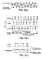
- Fig. 5 shows output voltage waveforms of the R, S and T phases of the AC motor driving apparatus 100 and voltage waveforms applied between the R phase and the S phase of the AC linear synchronous motor 4.
- Fig. 5 (a) is a view showing sine wave control signals having frequency equal to a fundamental frequency and a carrier of triangle wave having a frequency higher than the frequency of the sine wave control signals are convoluted and an inverter is commutated at cross points. Control of frequency and magnitude of output voltage is performed by adjusting the amplitude and frequency of sine wave signals. The carrier frequency is used to determine chopping times of output voltage and frequency of harmonic component contained in the output.
- Fig. 5 shows output voltage waveforms of the R, S and T phases of the AC motor driving apparatus 100 and voltage waveforms applied between the R phase and the S phase of the AC linear synchronous motor 4.
- Fig. 5 (a) is a view showing sine wave control signals having frequency equal to a fundamental frequency and a carrier of triangle wave having a frequency higher than the frequency of the sine wave
- FIG. 5(b) shows R-phase, S-phase and T-phase output voltage waveforms obtained by chopping of the output voltages by the above-described method, and the voltage between every two of these phases ( Fig. 5(b) shows voltage between R-S phases) are adjusted to be sine wave (lower harmonic component is removed).
- Fig. 5(c) shows an output voltage waveform of a part of the voltage between the R phase and the S phase shown in Fig. 5 (b) and a waveform of the exciting coil then.
- the carrier frequency is 8 kHz and the time constant of the AC linear synchronous motor 4 is 11 ⁇ s
- the current does not follow the voltage as shown in the lower view of Fig. 5 (c) , and undulations appear in the current waveform.
- the exciting coil current waveform of the AC linear synchronous motor 4 does not become an accurate sine wave and the current control becomes difficult.
- time constant adjusting coils 111 for adjusting the time constant of the AC linear synchronous motor are added at the output end of PWM.
- the time constant adjusting coils 111 added here are preferably determined by relation with carrier frequency.
- the carrier frequency is 8 kHz (period 125 ⁇ s)
- the time constant adjusting coils 111 are preferably provided to make the time constant of the AC linear synchronous motor 4 greater (120 ⁇ s or more), which is more preferably 2 to 5 times greater than the carrier frequency period.
- time constant adjusting coils 111 are added at the output end of the AC motor driving apparatus 100 corresponding to the carrier frequency, undulations in the exciting coil current waveform as shown in Fig. 5(c) can be prevented and stable control of the AC linear synchronous motor 4 is allowed.
- the time constant can be adjusted by combining the time constant adjusting coils 111 with condensers.
- Fig. 6(a) shows a current waveform of the AC linear synchronous motor 4 of which the inductance of the exciting coils is 22 ⁇ H
- Fig. 6(b) shows a current waveform of the AC linear synchronous motor obtained when 1000 ⁇ H is added by the time constant adjusting coils 111.
- the time constant adjusting coil 111 is not provided, the current cannot follow the voltage and shows large undulations (triangle waveform: Fig. 6(a) ).
- the time constant adjusting coils 111 are added, the current waveform does not include undulation ( Fig. 6(b) ) and can be made close to as sine wave.
- Fig. 7 is a view illustrating an embodiment where the time constant adjusting coils 111 for adjusting the time constant of the AC linear synchronous motor 4 are added as a time constant adjusting part 101 and switching elements 112 are corrected in parallel with the time constant adjusting coils 111.
- the AC linear synchronous motor 4 is started by the AC motor driving apparatus 100 supplying a starting current to the AC linear synchronous motor 4.
- the starting current is increased up to a predetermined current value as soon as possible.
- the rise time of the starting current is determined by the time constant of the AC linear synchronous motor 4 including the time constant adjusting coils 111, at starting, addition of the time constant adjusting coils 111 delays rising of current as shown in Fig. 8 .
- the switching elements 112 are provided in parallel with the respective time constant adjusting coils 111 and until the starting current rises, they are controlled to be on so that the starting current passes through the triac 112.
- the triac is used as the switching element, however, a photo triac coupler, solid state relay or any other element capable of carrying current bidirectionally may be used in place thereof.
- the triacs 112 are switched off and the driving current of the AC linear synchronous motor 4 are controlled to pass through the time constant adjusting coils 111.
- This control enables stable control even if the AC linear synchronous motor has an extremely small time constant, for example, 1 ⁇ s or less.
- the ON/OFF time shown in Fig. 8 shows a carrier period of the PWM device.
- the vertical axis indicates currents (Arms) determined by the motor parameter.
- a square shaped linear motor was selected as an AC linear synchronous motor of the linear motor actuator.
- This square shaped linear motor has a rated power of 0.13 N and a maximum power of 0.4 N.
- the rated current is 0.27 Arms and the maximum current is 0.8 Arms.
- the electric resistance is 2 ⁇
- the inductance is 22 ⁇ H
- the time constant of this AC motor is 11 ⁇ H.
- time constant adjusting coil 111 2000 ⁇ H coil was added to each phase at the output end of the AC motor driving apparatus 100, and the time constant was adjusted to 412 ⁇ s. Then, the AC motor did not vibrate and there occurred no noise, and stable control of the linear motor actuator was allowed.
- a round shaped linear motor was selected as an AC linear synchronous motor of the linear motor actuator.
- This round shaped linear motor has a rated power of 0.048 N and a maximum power of 0.145 N.
- the rated current is 0.1 Arms and the maximum current is 0.3 Arms.
- the electric resistance is 13.2 ⁇
- the inductance is 16 ⁇ H and the time constant of this AC motor is 1.21 ⁇ H.
Landscapes
- Engineering & Computer Science (AREA)
- Power Engineering (AREA)
- Control Of Linear Motors (AREA)
- Control Of Ac Motors In General (AREA)
- Inverter Devices (AREA)
Abstract
Description
- The present invention relates to control of an AC motor, and particularly to an AC motor driving apparatus and control method for controlling and driving a motor having small time constant by using the PWM (Pulse Width Modulation) system of controlling pulse number, pulse interval, pulse width and the like of pulse-shaped voltages and outputting voltages equivalent to output frequencies.
- A linear motor actuator, which is greatly used in various tables of machine tools, moving parts of industrial robots, various conveyer apparatus and the like, has functions of giving linear motion to a movable body such as a table and stopping the movable body at a predetermined position. This linear motor actuator is driven by using an AC linear synchronous motor. The AC linear synchronous motor is structured to have a stator and a mover, and an exciting coil of copper wire is formed on a part of the stator or the mover. When exciting current is made to pass through the exciting coil to generate a driving force, linear movement is achieved.
- Here, the rotational speed of the AC motor (linear movement speed of the linear motor) is fundamentally proportional to a supplied frequency. Hence, the AC motor is controlled by a method of once converting current from a commercial power source into direct current and then converting the direct current as the power source into alternate current having any frequency. In the AC motor control using an inverter as a power converter for converting DC power to AC power, the PWM (Pulse Width Modulation) system is often used in which the pulse width ratio is changed by controlling the width of output voltage wave or chopping a half cycle of the output voltage wave.
- In the AC motor control of controlling the number of pulses, the pulse interval, the pulse width and the off time to output a voltage equivalent corresponding to output frequency, the time constant of the motor is an important parameter. However, as the mover of the conventional linear motor actuator has a weight of a certain level or more, the influence of the electric parameter of the AC motor on the actuator is very small as compared with the influence of the mechanical time constant (inertia) and insignificant.
- Associated with downsizing and weight reduction of the liner motor actuator, there has been produced an ultra-compact AC linear synchronous motor having only a few turns of exciting coil, which makes apparent the problems that 1) when the PWM system is used as-is in the ultra-compact AC linear synchronous motor, the number of turns of the exciting coil is very small and the time constant (L/R) becomes very small, resulting in quick current response to the voltage and uncontrollability of the current, and 2) although the waveform of current passing through the exciting coil is preferably a sine wave, harmonic components are convoluted to vibrate the motor or cause noise, and the like.
- The following
patent document 1 discloses a related art of using the inductance of the exciting coil as a motor control parameter in the AC motor control. Thepatent document 1 relates to a motor and its control method. According to thepatent document 1, there was a problem that although the inductance of the motor coil varies depending on the number of rotation times of the motor, the temperature and the like, the motor applied voltage and motor current were calculated with use of a fixed value of the inductance, resulting in reduction in the motor efficiency. As measures to solve this problem, thepatent document 1 discloses extracting a motor constant based on a use environment of the motor and generating a control signal based on the extracted motor constant. However, the technique of thepatent document 1 does not serve to solve the problems of a ultra-compact AC motor control having an extremely small time constant, which differs from the present invention, and there is hardly any other document which discloses the technique to solve such problems. - [Patent Document 1] Japanese Patent Laid-open Publication No.
2002-369598 - The present invention has an object to provide an AC motor driving apparatus and an AC motor control method capable of utilizing the conventional PWM system as-is even in an ultra-compact AC motor having an extremely few turns of exciting coil and preventing occurring of vibration and noise.
- The present invention is an AC motor driving apparatus comprising an inverter converting a DC voltage to an AC voltage and supplying the AC voltage at least to an AC motor; a PWM device controlling a magnitude and a frequency of an output voltage of the inverter; and means for changing a time constant of the AC motor in accordance with a carrier frequency of the PWM device.
- As the AC motor with an extremely few turns (several turns) of motor exciting coil has a very small time constant (L/R), a current response to the voltage becomes quick. This results in difficulty in motor control. However, if the time constant of the AC motor is adjusted in accordance with the PWM carrier frequency, the current waveform of the exciting coil is made close to the sine wave and this enables control of the ultra-compact AC motor having a small time constant.
- As the time adjusting coil and/or condenser for adjusting the motor time constant is provided between the PWM device and the AC motor and its capacity is controlled in accordance with the carrier frequency, it is possible to achieve an appropriate motor time constant and thereby to control the ultra-compact AC motor.
- In addition, the switching element is provided in parallel with the time constant adjusting coil, and the switching element is turned on so that current does not pass through the time constant adjusting coil during a time period of pulses first output by the PWM device at starting of the AC motor. This control makes it possible to reduce the time constant at starting up of the AC motor and hasten rising of the current. After rising up of the current, the switching element is turned off and thereby the current waveform becomes even thereby enabling ideal control.
- According to the present invention, it is possible to provide an AC motor driving apparatus capable of utilizing the conventional PWM system as-is even in an ultra-compact AC motor having an extremely few turns of exciting coil and preventing vibration and noise of the motor.
-
-
Fig. 1 is a perspective view showing an example of a linear motor actuator; -
Fig. 2 is a perspective view showing the linear motor actuator ofFig. 1 from which a table plate is removed; -
Fig. 3 is a perspective view showing details of a motor part of the linear motor actuator ofFig. 1 ; -
Fig. 4 is a view showing connection between an equivalent circuit of the AC linear synchronous motor and the ACmotor driving apparatus 100 having coils and condensers adjusting the motor time constant; -
Fig. 5 shows waveforms of exciting coil current when the motor time constant is small, an R-S phase voltage waveform and output voltage pulses by the pulse width modulating system; -
Fig. 6 shows a waveform of exciting coil current when the coil is inserted into the ACmotor driving apparatus 100 so as to adjust the time constant of the AC linear synchronous motor and a waveform of exciting coil current when the coil is not inserted; -
Fig. 7 is a view showing connection between the AC motor and the motor driving apparatus having, as a time constant adjustingpart 101, the time constant adjustingcoil 111 and theswitching element 112 connected in parallel therewith; -
Fig. 8 is a view for comparing time-current characteristics when theswitch element 112 is on at starting up and is turned off after the current has reached its rated value with time-current characteristics when theswitching element 112 remains off (the horizontal axis indicates times and the vertical axis indicates current). -
- 1
- base member
- 2
- raceway rail
- 3
- slide table
- 4
- AC linear synchronous motor
- 5
- slide block
- 6
- table plate
- 40
- stator magnet
- 41
- exciting coil
- 100
- AC motor driving apparatus
- 101
- time constant adjusting part
- 111
- time constant adjusting coil
- 112
- switching element (triac)
-
Fig. 1 is a perspective view showing an embodiment of a linear motor actuator to which an AC motor driving apparatus of the present invention is applied. This linear motor actuator has abase member 1; araceway rail 2 laying on thebase member 1; a slide table 3 capable of moving back and forth along theraceway rail 2; an AC linear synchronous motor 4 for driving the slide table 3 above thebase member 1; and a ACmotor driving apparatus 100. Here, the ACmotor driving apparatus 100 is equipped with a PWM device having a carrier frequency of 8 kHz. - The
base member 1 which is a component of the linear motor actuator has abottom plate 10 and a pair ofside walls bottom plate 10, and thebase member 1 is formed like a channel. In thebottom plate 10, there is formed a mountinggroove 12 for positioning theraceway rail 2 along the longitudinal direction of thebase member 1. - In addition, the slide table 3 has a slide block 5 moving along the
raceway rail 2 and atable plate 6 fixed to the slide block 5. -
Fig. 2 is a perspective view showing the linear motor actuator ofFig. 1 from which thetable plate 6 is removed. The slid block 5 operates in combination with theraceway rail 2 to constitute a linear guide and guides thetable plate 6 along theraceway rail 2. - The AC linear synchronous motor 4 is a synchronous linear motor having a time constant of 11 µs, an electric resistance of 2 Ω, and an inductance of 22 µH, and has a plurality of
stator magnets 40 arranged in a line on each of theside walls 11 of thebase member 1 and a pair ofexciting coils 41 facing thestator magnets 40 with a slight space interposed therebetween and mounted on the slide table 3. - On each
side wall 11 of thebase member 1, thestator magnets 40 are arranged in such a manner that theexciting coils 41 face the N pole and the S pole of themagnets 40, alternately. Thesestator magnets 40 are arranged on holdingplates 42 made of synthetic resin and each of the holdingplates 42 is adhered to an inner surface of theside wall 11 of thebase member 1, thereby facilitating arrangement of thestator magnets 40 on thebase member 1. Here, thestator magnets 40 are formed integral with the holdingplate 42 by injection molding. - Besides, each of the
exciting coils 41 consists of turns of wire wound on a core member made of ferromagnetic material such as iron or the like. In this linear motor actuator, the pairedexciting coils 41 are provided facing thestator magnets 40 arranged on theside walls 11 of thebase member 1. In the example shown inFig. 2 , these pairedexciting coils core plate 43. -
Fig. 3 is a perspective view showing bonding of thetable plate 6 and theexciting coils 41, also showing the cross sectional structure of theexciting coils 41. Theexciting coil 41 is formed of turns ofcoil 44 wound on thecore plate 43. Thiscore plate 43 has acenter part 43a bonded to thetable plate 6 and a pair ofcore parts center part 43a. In each of thecore parts 43b, slots are formed for receiving thecoils 44. - In other words, as the
coils 44 are wound on eachcore part 43b, the pairedexciting coils 41 are formed integral with thecore plates 43. Each of theexciting coils 41 has threephase coils 44 of U phase, V phase and W phase. When three-phase alternate current supplied from the ACmotor driving apparatus 100 is made to pass through thecoils 44, there is generated thrust in theexciting coils 41 along the arrangement direction of thestator magnets 40. - Fixed onto one side wall of the
base member 1 is abracket 13 having an approximately L-shaped cross section (Fig. 2 ). On an upper surface of thisbracket 13, there is a linear scale fixed thereto along the longitudinal direction of thebase member 1. In addition, on the lower surface of thetable plate 6, anencoder 15 is fixed thereto for reading thelinear scale 14 as thetable plate 6 moves. Theencoder 15 outputs pulse signals at intervals corresponding to the moving speed of thetable plate 6. - Current carrying to the
exciting coils 41 and transmission of output signals of theencoder 15 are performed with use of flexible printed circuits (FPCs), and these FPCs are fixed onto the lower surface of thetable plate 6, drawn from the side of thebase member 1 and connected to the ACmotor driving apparatus 100. - In the thus-structured linear motor actuator, when three-phase alternate current passes through the exiting
coils 41 fixed onto thetable plate 6, thrust is produced in theexciting coils 41 along the arrangement direction of thestator magnets 40 and the slide table 3 moves back and forth along theraceway rail 2. Theencoder 15 reads thelinear scale 14 and outputs signals in accordance with the moving speed and the moving distance of the slide table 3. As the current passage to theexciting coils 41 is controlled with reference to output signals of theencoder 15, back-and-forth motion of the slide table 3 can be controlled freely. -
Fig. 4 is a schematic showing connection between the above-described AC linear synchronous motor 4 and the ACmotor driving apparatus 100 controlling this. At the voltage output end of the ACmotor driving apparatus 100, there are provided timeconstant adjusting coils 111 for adjusting the time constant of the AC motor. The ACmotor driving apparatus 100 controls the AC linear synchronous motor 4 by way of the PWM system. Here, the timeconstant adjusting coils 111 may be provided in combination with condensers (Fig. 4 , lower figure). -
Fig. 5 shows output voltage waveforms of the R, S and T phases of the ACmotor driving apparatus 100 and voltage waveforms applied between the R phase and the S phase of the AC linear synchronous motor 4.Fig. 5 (a) is a view showing sine wave control signals having frequency equal to a fundamental frequency and a carrier of triangle wave having a frequency higher than the frequency of the sine wave control signals are convoluted and an inverter is commutated at cross points. Control of frequency and magnitude of output voltage is performed by adjusting the amplitude and frequency of sine wave signals. The carrier frequency is used to determine chopping times of output voltage and frequency of harmonic component contained in the output.Fig. 5(b) shows R-phase, S-phase and T-phase output voltage waveforms obtained by chopping of the output voltages by the above-described method, and the voltage between every two of these phases (Fig. 5(b) shows voltage between R-S phases) are adjusted to be sine wave (lower harmonic component is removed). -
Fig. 5(c) shows an output voltage waveform of a part of the voltage between the R phase and the S phase shown inFig. 5 (b) and a waveform of the exciting coil then. When the carrier frequency is 8 kHz and the time constant of the AC linear synchronous motor 4 is 11 µs, the current does not follow the voltage as shown in the lower view ofFig. 5 (c) , and undulations appear in the current waveform. As a result, the exciting coil current waveform of the AC linear synchronous motor 4 does not become an accurate sine wave and the current control becomes difficult. - Here, as shown in
Fig. 4 , timeconstant adjusting coils 111 for adjusting the time constant of the AC linear synchronous motor are added at the output end of PWM. The timeconstant adjusting coils 111 added here are preferably determined by relation with carrier frequency. For example, when the carrier frequency is 8 kHz (period 125 µs), the timeconstant adjusting coils 111 are preferably provided to make the time constant of the AC linear synchronous motor 4 greater (120 µs or more), which is more preferably 2 to 5 times greater than the carrier frequency period. - Thus, as the time
constant adjusting coils 111 are added at the output end of the ACmotor driving apparatus 100 corresponding to the carrier frequency, undulations in the exciting coil current waveform as shown inFig. 5(c) can be prevented and stable control of the AC linear synchronous motor 4 is allowed. Besides, as described above, the time constant can be adjusted by combining the timeconstant adjusting coils 111 with condensers. -
Fig. 6(a) shows a current waveform of the AC linear synchronous motor 4 of which the inductance of the exciting coils is 22 µH andFig. 6(b) shows a current waveform of the AC linear synchronous motor obtained when 1000 µH is added by the time constant adjusting coils 111. When the timeconstant adjusting coil 111 is not provided, the current cannot follow the voltage and shows large undulations (triangle waveform:Fig. 6(a) ). When the timeconstant adjusting coils 111 are added, the current waveform does not include undulation (Fig. 6(b) ) and can be made close to as sine wave. -
Fig. 7 is a view illustrating an embodiment where the timeconstant adjusting coils 111 for adjusting the time constant of the AC linear synchronous motor 4 are added as a timeconstant adjusting part 101 and switchingelements 112 are corrected in parallel with the time constant adjusting coils 111. The AC linear synchronous motor 4 is started by the ACmotor driving apparatus 100 supplying a starting current to the AC linear synchronous motor 4. Preferably, the starting current is increased up to a predetermined current value as soon as possible. - As the rise time of the starting current is determined by the time constant of the AC linear synchronous motor 4 including the time
constant adjusting coils 111, at starting, addition of the timeconstant adjusting coils 111 delays rising of current as shown inFig. 8 . - However, as shown in
Fig. 7 , the switching elements 112 (triacs) are provided in parallel with the respective timeconstant adjusting coils 111 and until the starting current rises, they are controlled to be on so that the starting current passes through thetriac 112. With this control, as shown inFig. 8 , the starting current rises immediately and controllability of the AC linear synchronous motor 4 is improved dramatically. In this embodiment, the triac is used as the switching element, however, a photo triac coupler, solid state relay or any other element capable of carrying current bidirectionally may be used in place thereof. - Once the starting current has reached a rated value, the
triacs 112 are switched off and the driving current of the AC linear synchronous motor 4 are controlled to pass through the time constant adjusting coils 111. This control enables stable control even if the AC linear synchronous motor has an extremely small time constant, for example, 1 µs or less. Here, the ON/OFF time shown inFig. 8 shows a carrier period of the PWM device. Besides, the vertical axis indicates currents (Arms) determined by the motor parameter. - A square shaped linear motor was selected as an AC linear synchronous motor of the linear motor actuator. This square shaped linear motor has a rated power of 0.13 N and a maximum power of 0.4 N. The rated current is 0.27 Arms and the maximum current is 0.8 Arms. The electric resistance is 2 Ω, the inductance is 22 µH and the time constant of this AC motor is 11 µH. This AC linear synchronous motor has a winding of ϕ=0.11 mm having 48 turns.
- As the time
constant adjusting coil 111, 2000 µH coil was added to each phase at the output end of the ACmotor driving apparatus 100, and the time constant was adjusted to 412 µs. Then, the AC motor did not vibrate and there occurred no noise, and stable control of the linear motor actuator was allowed. - A round shaped linear motor was selected as an AC linear synchronous motor of the linear motor actuator. This round shaped linear motor has a rated power of 0.048 N and a maximum power of 0.145 N. The rated current is 0.1 Arms and the maximum current is 0.3 Arms. The electric resistance is 13.2 Ω, the inductance is 16 µH and the time constant of this AC motor is 1.21 µH. This AC linear synchronous motor has a winding of ϕ=0.07 mm having 60 turns.
- As a time
constant adjusting coil 111 of this linear synchronous motor, 3000 µH coil was added to each phase at the output end of the ACmotor driving apparatus 100, and the time constant was adjusted to 324 µs. Then, the AC motor did not vibrate and there occurred no noise, and stable control of the linear motor actuator was allowed. - The present specification is based on Japanese Patent Applications No.
2006-98311 filed on March 31, 2006 2006-124930 filed on April 28, 2006
Claims (12)
- An AC motor driving apparatus comprising: an inverter; a PWM (pulse width modulation) device for PWM controlling an output voltage to be supplied at least to an AC motor; and means for changing a time constant of the AC motor in accordance with a carrier frequency of the PWM device.
- The AC motor driving apparatus according to claim 1, further comprising a time constant adjusting coil'and/or condenser at an output end of the PWM device.
- The AC motor driving apparatus according to claim 2, wherein a capacity of the time constant adjusting coil and/or condenser is controlled in such a manner that the time constant of the AC motor is greater than or equal to a period of the carrier frequency of the PWM device.
- The AC motor driving apparatus according to claim 3, wherein the capacity of the time constant adjusting coil and/or condenser is controlled in such a manner that the time constant of the AC motor is two to five times greater than the period of the carrier frequency.
- The AC motor driving apparatus according to claim 4, further comprising a switching element connected in parallel with the time constant adjusting coil.
- The AC motor driving apparatus according to claim 5, wherein the switching element is an element capable of carrying current bidirectionally.
- The AC motor driving apparatus according to claim 5 or 6, further comprising means for controlling the switching element in such a manner that current does not pass through the time constant adjusting coil at least during first pulses output from the PWM device when the AC motor starts up.
- An AC motor control method using a PWM (pulse width modulation) system of controlling at least one of a pulse number, a pulse interval and a pulse width of a pulse-shaped AC voltage to adjust a voltage to be supplied to an AC motor, the AC motor control method comprising:changing a time constant of the AC motor in accordance with a carrier frequency of the PWM system to control the AC motor.
- The AC motor control method according to claim 8, further comprising: arranging a time constant adjusting coil and/or condenser between an output end of the PWM system and the AC motor and changing a capacity of the time constant adjusting coil and/or condenser to adjust the time constant of the AC motor.
- The AC motor control method according to claim 8 or 9, further comprising: controlling a capacity of the time constant adjusting coil and/or condenser in such a manner that the time constant of the AC motor is greater than or equal to a period of the carrier frequency of the PWM system.
- The AC motor control method according to claim 10, wherein controlling of the capacity of the time constant adjusting coil and/or condenser is performed in such a manner that the time constant of the AC motor is two to five times greater than the period of the carrier frequency.
- The AC motor control method according to any one of claims 9 to 11, further comprising: connecting a switching element in parallel with the time constant adjusting coil; and controlling the switching element in such a manner that current does not pass through the time constant adjusting coil at least during first pulses output from the PWM system when the AC motor starts up.
Applications Claiming Priority (3)
| Application Number | Priority Date | Filing Date | Title |
|---|---|---|---|
| JP2006098311 | 2006-03-31 | ||
| JP2006124930 | 2006-04-28 | ||
| PCT/JP2007/056261 WO2007114109A1 (en) | 2006-03-31 | 2007-03-26 | Ac motor driving apparatus and control method |
Publications (3)
| Publication Number | Publication Date |
|---|---|
| EP2012423A1 true EP2012423A1 (en) | 2009-01-07 |
| EP2012423A4 EP2012423A4 (en) | 2016-05-11 |
| EP2012423B1 EP2012423B1 (en) | 2020-04-29 |
Family
ID=38563378
Family Applications (1)
| Application Number | Title | Priority Date | Filing Date |
|---|---|---|---|
| EP07739699.2A Active EP2012423B1 (en) | 2006-03-31 | 2007-03-26 | Ac motor driving apparatus and control method |
Country Status (6)
| Country | Link |
|---|---|
| US (1) | US8076890B2 (en) |
| EP (1) | EP2012423B1 (en) |
| JP (1) | JP5165554B2 (en) |
| CN (1) | CN101411053B (en) |
| TW (1) | TWI408890B (en) |
| WO (1) | WO2007114109A1 (en) |
Families Citing this family (5)
| Publication number | Priority date | Publication date | Assignee | Title |
|---|---|---|---|---|
| WO2007026270A1 (en) * | 2005-08-29 | 2007-03-08 | Koninklijke Philips Electronics, N.V. | Ironless magnetic linear motors having levitating and transversal force capacities |
| EP2104221A1 (en) * | 2008-03-22 | 2009-09-23 | Grundfos Management A/S | Method for controlling a multi-phase electromotor operated in a star circuit |
| JP5558752B2 (en) * | 2009-07-30 | 2014-07-23 | 日立オートモティブシステムズ株式会社 | Power converter |
| JP5549384B2 (en) * | 2010-06-03 | 2014-07-16 | 日産自動車株式会社 | Electric motor control device and electric motor control system |
| TWI487268B (en) * | 2013-06-03 | 2015-06-01 | 大同股份有限公司 | Exciter circuit of synchronous motor and operation method thereof |
Family Cites Families (24)
| Publication number | Priority date | Publication date | Assignee | Title |
|---|---|---|---|---|
| JPS587592B2 (en) * | 1976-02-07 | 1983-02-10 | フジテツク株式会社 | Elevator speed control device |
| US4383209A (en) * | 1980-10-15 | 1983-05-10 | Minnesota Mining And Manufacturing Company | Control system for transducer positioning motor |
| JPS57173396A (en) * | 1981-04-17 | 1982-10-25 | Hitachi Ltd | Controlling method for pwm control converter |
| JPS60187120A (en) * | 1984-03-07 | 1985-09-24 | Toshiba Corp | Monostable multivibrator circuit |
| JP2508757B2 (en) * | 1987-10-13 | 1996-06-19 | ソニー株式会社 | Motor drive circuit |
| JPH0326486A (en) * | 1989-06-19 | 1991-02-05 | Matsushita Electric Ind Co Ltd | Chucking mechanism for adjusting bolt |
| JP2932080B2 (en) | 1990-03-13 | 1999-08-09 | 株式会社安川電機 | Inverter control method |
| JP3118721B2 (en) * | 1990-08-30 | 2000-12-18 | 富士通株式会社 | motor |
| IT1259115B (en) * | 1992-06-17 | 1996-03-11 | Askoll Spa | ELECTRONIC DEVICE FOR STARTING A SYNCHRONOUS MOTOR WITH PERMANENT MAGNET ROTOR |
| US5444351A (en) * | 1993-07-06 | 1995-08-22 | Nissan Motor Co., Ltd. | System and method for controlling induction motor applicable to electric motor-driven vehicle |
| US5444595A (en) * | 1993-09-27 | 1995-08-22 | Nippondenso Co., Ltd. | Load drive apparatus including power transistor protection circuit from overcurrent |
| JP3333793B2 (en) * | 1994-09-22 | 2002-10-15 | サンデン株式会社 | Brushless motor device |
| US5796545A (en) * | 1995-06-07 | 1998-08-18 | Sgs-Thomson Microelectronics, Inc. | Device and method for calibrating a time constant of one or more filter circuits |
| JPH10210757A (en) * | 1997-01-27 | 1998-08-07 | Matsushita Electric Works Ltd | Zero current turn off type pwm inverter device |
| US6208098B1 (en) * | 1998-03-02 | 2001-03-27 | Yaskawa Electric America, Inc. | Variable frequency drive noise attenuation circuit |
| US6208537B1 (en) * | 1999-09-28 | 2001-03-27 | Rockwell Technologies, Llc | Series resonant sinewave output filter and design methodology |
| JP2002369598A (en) | 2001-06-11 | 2002-12-20 | Toyota Industries Corp | Motor and control method therefor |
| JP2003037993A (en) * | 2001-07-25 | 2003-02-07 | Nikon Corp | Actuator drive circuit, stage device, and exposure device |
| JP2003219691A (en) * | 2002-01-17 | 2003-07-31 | Meidensha Corp | Drive system for permanent-magnet synchronous motor and test method therefor |
| JP4356977B2 (en) * | 2003-12-04 | 2009-11-04 | キヤノン株式会社 | Power supply apparatus and recording apparatus provided with the power supply apparatus |
| JP3938920B2 (en) * | 2004-04-02 | 2007-06-27 | 日本サーボ株式会社 | Stepping motor control device |
| JP2006098311A (en) | 2004-09-30 | 2006-04-13 | Clarion Co Ltd | Navigation system |
| JP4722451B2 (en) | 2004-10-26 | 2011-07-13 | 株式会社竹中工務店 | Building construction method |
| JP5617211B2 (en) * | 2008-11-04 | 2014-11-05 | 富士電機株式会社 | Inverter unit cooling capacity measurement method |
-
2007
- 2007-03-26 US US12/295,069 patent/US8076890B2/en active Active
- 2007-03-26 WO PCT/JP2007/056261 patent/WO2007114109A1/en not_active Ceased
- 2007-03-26 CN CN2007800106659A patent/CN101411053B/en active Active
- 2007-03-26 EP EP07739699.2A patent/EP2012423B1/en active Active
- 2007-03-26 JP JP2008508537A patent/JP5165554B2/en active Active
- 2007-03-30 TW TW096111258A patent/TWI408890B/en active
Non-Patent Citations (1)
| Title |
|---|
| See references of WO2007114109A1 * |
Also Published As
| Publication number | Publication date |
|---|---|
| TWI408890B (en) | 2013-09-11 |
| CN101411053A (en) | 2009-04-15 |
| EP2012423A4 (en) | 2016-05-11 |
| US20090322265A1 (en) | 2009-12-31 |
| EP2012423B1 (en) | 2020-04-29 |
| WO2007114109A1 (en) | 2007-10-11 |
| CN101411053B (en) | 2011-09-28 |
| TW200746612A (en) | 2007-12-16 |
| JP5165554B2 (en) | 2013-03-21 |
| US8076890B2 (en) | 2011-12-13 |
| JPWO2007114109A1 (en) | 2009-08-13 |
Similar Documents
| Publication | Publication Date | Title |
|---|---|---|
| EP0397514B1 (en) | Bridge inverters and the control thereof | |
| US5166591A (en) | Current chopping strategy for generating action in switched reluctance machines | |
| US8076890B2 (en) | AC motor driving apparatus and control method | |
| CA2543354C (en) | Magnetic gearing of permanent magnet brushless motors | |
| WO2006038510A1 (en) | Linear motor system | |
| CN1269305C (en) | Controller for AC motor | |
| RU2387073C2 (en) | Method to control mechanically switched motor | |
| EP2549640A2 (en) | Electronic commutator circuits | |
| JP5003173B2 (en) | AC motor winding switching device and winding switching system thereof | |
| JP3676863B2 (en) | Circuit device for controlling an electronically rectified motor | |
| CN105245037B (en) | Coreless stepping motor and control method thereof | |
| US6566839B2 (en) | Switched capacitor motor driver | |
| Copt et al. | Dynamic winding reconfiguration of a brushless DC motor | |
| Wale et al. | Novel converter topologies for a two-phase switched reluctance motor with fully pitched windings | |
| Sengupta et al. | Experimental investigations on a novel laboratory prototype of axial flux switched reluctance motor | |
| JP3912347B2 (en) | Linear motor drive device | |
| Hirayama et al. | Method of Applying Force Distribution Function for Linear Switched Reluctance Motor Driven by Current Source Inverter | |
| GB2124831A (en) | Electric torque converter | |
| Oh et al. | A novel control scheme for low cost SRM drive | |
| JPH1066327A (en) | Movable magnet linear dc motor | |
| KR20160139952A (en) | Power conversion system for electric vehicles | |
| JPH0223092A (en) | Motor operated by output torque designated by ac power source | |
| Lu et al. | Analysis of transverse-flux switched-flux permanent magnet linear motor | |
| Locci et al. | Electronic control of a linear reluctance motor | |
| Nicolae-Daniel et al. | Control of a 6/4 switched reluctance motor by means of a DC voltage supply with DC high voltage intermediary circuit |
Legal Events
| Date | Code | Title | Description |
|---|---|---|---|
| PUAI | Public reference made under article 153(3) epc to a published international application that has entered the european phase |
Free format text: ORIGINAL CODE: 0009012 |
|
| 17P | Request for examination filed |
Effective date: 20081030 |
|
| AK | Designated contracting states |
Kind code of ref document: A1 Designated state(s): AT BE BG CH CY CZ DE DK EE ES FI FR GB GR HU IE IS IT LI LT LU LV MC MT NL PL PT RO SE SI SK TR |
|
| AX | Request for extension of the european patent |
Extension state: AL BA HR MK RS |
|
| DAX | Request for extension of the european patent (deleted) | ||
| RBV | Designated contracting states (corrected) |
Designated state(s): CH DE FR LI |
|
| RA4 | Supplementary search report drawn up and despatched (corrected) |
Effective date: 20160411 |
|
| RIC1 | Information provided on ipc code assigned before grant |
Ipc: H02M 1/12 20060101ALI20160405BHEP Ipc: H02P 27/08 20060101ALI20160405BHEP Ipc: H02P 6/08 20060101ALI20160405BHEP Ipc: H02P 25/06 20160101ALI20160405BHEP Ipc: H02P 6/20 20160101ALI20160405BHEP Ipc: H02P 6/10 20060101AFI20160405BHEP Ipc: H02M 7/48 20070101ALI20160405BHEP |
|
| 17Q | First examination report despatched |
Effective date: 20180809 |
|
| REG | Reference to a national code |
Ref country code: DE Ref legal event code: R079 Ref document number: 602007060152 Country of ref document: DE Free format text: PREVIOUS MAIN CLASS: H02P0006100000 Ipc: H02P0006200000 |
|
| GRAP | Despatch of communication of intention to grant a patent |
Free format text: ORIGINAL CODE: EPIDOSNIGR1 |
|
| RIC1 | Information provided on ipc code assigned before grant |
Ipc: H02M 1/12 20060101ALI20191017BHEP Ipc: H02P 6/20 20160101AFI20191017BHEP Ipc: H02P 25/06 20160101ALN20191017BHEP Ipc: H02P 27/08 20060101ALI20191017BHEP |
|
| RIC1 | Information provided on ipc code assigned before grant |
Ipc: H02P 6/20 20160101AFI20191021BHEP Ipc: H02M 1/12 20060101ALI20191021BHEP Ipc: H02P 27/08 20060101ALI20191021BHEP Ipc: H02P 25/06 20160101ALN20191021BHEP |
|
| INTG | Intention to grant announced |
Effective date: 20191118 |
|
| GRAS | Grant fee paid |
Free format text: ORIGINAL CODE: EPIDOSNIGR3 |
|
| GRAA | (expected) grant |
Free format text: ORIGINAL CODE: 0009210 |
|
| STAA | Information on the status of an ep patent application or granted ep patent |
Free format text: STATUS: THE PATENT HAS BEEN GRANTED |
|
| AK | Designated contracting states |
Kind code of ref document: B1 Designated state(s): CH DE FR LI |
|
| REG | Reference to a national code |
Ref country code: CH Ref legal event code: EP |
|
| REG | Reference to a national code |
Ref country code: CH Ref legal event code: NV Representative=s name: BOVARD AG PATENT- UND MARKENANWAELTE, CH |
|
| REG | Reference to a national code |
Ref country code: DE Ref legal event code: R096 Ref document number: 602007060152 Country of ref document: DE |
|
| REG | Reference to a national code |
Ref country code: DE Ref legal event code: R097 Ref document number: 602007060152 Country of ref document: DE |
|
| PLBE | No opposition filed within time limit |
Free format text: ORIGINAL CODE: 0009261 |
|
| STAA | Information on the status of an ep patent application or granted ep patent |
Free format text: STATUS: NO OPPOSITION FILED WITHIN TIME LIMIT |
|
| 26N | No opposition filed |
Effective date: 20210201 |
|
| P01 | Opt-out of the competence of the unified patent court (upc) registered |
Effective date: 20230920 |
|
| PGFP | Annual fee paid to national office [announced via postgrant information from national office to epo] |
Ref country code: CH Payment date: 20250401 Year of fee payment: 19 |
|
| REG | Reference to a national code |
Ref country code: CH Ref legal event code: U11 Free format text: ST27 STATUS EVENT CODE: U-0-0-U10-U11 (AS PROVIDED BY THE NATIONAL OFFICE) Effective date: 20260401 |
|
| PGFP | Annual fee paid to national office [announced via postgrant information from national office to epo] |
Ref country code: DE Payment date: 20260319 Year of fee payment: 20 |
|
| PGFP | Annual fee paid to national office [announced via postgrant information from national office to epo] |
Ref country code: FR Payment date: 20260320 Year of fee payment: 20 |