EP2012307B1 - Système de séparation de sources sonores - Google Patents
Système de séparation de sources sonores Download PDFInfo
- Publication number
- EP2012307B1 EP2012307B1 EP08251991A EP08251991A EP2012307B1 EP 2012307 B1 EP2012307 B1 EP 2012307B1 EP 08251991 A EP08251991 A EP 08251991A EP 08251991 A EP08251991 A EP 08251991A EP 2012307 B1 EP2012307 B1 EP 2012307B1
- Authority
- EP
- European Patent Office
- Prior art keywords
- cost function
- separation matrix
- separation
- sound source
- value
- Prior art date
- Legal status (The legal status is an assumption and is not a legal conclusion. Google has not performed a legal analysis and makes no representation as to the accuracy of the status listed.)
- Active
Links
Images





Classifications
-
- G—PHYSICS
- G10—MUSICAL INSTRUMENTS; ACOUSTICS
- G10L—SPEECH ANALYSIS TECHNIQUES OR SPEECH SYNTHESIS; SPEECH RECOGNITION; SPEECH OR VOICE PROCESSING TECHNIQUES; SPEECH OR AUDIO CODING OR DECODING
- G10L21/00—Speech or voice signal processing techniques to produce another audible or non-audible signal, e.g. visual or tactile, in order to modify its quality or its intelligibility
- G10L21/02—Speech enhancement, e.g. noise reduction or echo cancellation
- G10L21/0272—Voice signal separating
- G10L21/028—Voice signal separating using properties of sound source
-
- G—PHYSICS
- G06—COMPUTING OR CALCULATING; COUNTING
- G06F—ELECTRIC DIGITAL DATA PROCESSING
- G06F18/00—Pattern recognition
- G06F18/20—Analysing
- G06F18/21—Design or setup of recognition systems or techniques; Extraction of features in feature space; Blind source separation
- G06F18/213—Feature extraction, e.g. by transforming the feature space; Summarisation; Mappings, e.g. subspace methods
- G06F18/2134—Feature extraction, e.g. by transforming the feature space; Summarisation; Mappings, e.g. subspace methods based on separation criteria, e.g. independent component analysis
- G06F18/21342—Feature extraction, e.g. by transforming the feature space; Summarisation; Mappings, e.g. subspace methods based on separation criteria, e.g. independent component analysis using statistical independence, i.e. minimising mutual information or maximising non-gaussianity
-
- G—PHYSICS
- G06—COMPUTING OR CALCULATING; COUNTING
- G06F—ELECTRIC DIGITAL DATA PROCESSING
- G06F18/00—Pattern recognition
- G06F18/20—Analysing
- G06F18/21—Design or setup of recognition systems or techniques; Extraction of features in feature space; Blind source separation
- G06F18/213—Feature extraction, e.g. by transforming the feature space; Summarisation; Mappings, e.g. subspace methods
- G06F18/2134—Feature extraction, e.g. by transforming the feature space; Summarisation; Mappings, e.g. subspace methods based on separation criteria, e.g. independent component analysis
- G06F18/21347—Feature extraction, e.g. by transforming the feature space; Summarisation; Mappings, e.g. subspace methods based on separation criteria, e.g. independent component analysis using domain transformations
-
- G—PHYSICS
- G10—MUSICAL INSTRUMENTS; ACOUSTICS
- G10L—SPEECH ANALYSIS TECHNIQUES OR SPEECH SYNTHESIS; SPEECH RECOGNITION; SPEECH OR VOICE PROCESSING TECHNIQUES; SPEECH OR AUDIO CODING OR DECODING
- G10L21/00—Speech or voice signal processing techniques to produce another audible or non-audible signal, e.g. visual or tactile, in order to modify its quality or its intelligibility
- G10L21/02—Speech enhancement, e.g. noise reduction or echo cancellation
- G10L21/0208—Noise filtering
- G10L21/0216—Noise filtering characterised by the method used for estimating noise
- G10L2021/02161—Number of inputs available containing the signal or the noise to be suppressed
- G10L2021/02166—Microphone arrays; Beamforming
Definitions
- the present invention relates to a sound source separation system.
- blind source separation As a method of separating a sound source without information of a transfer system according to a separation method based on an inverse filter, blind source separation (BSS) is suggested (see Reference Documents 1 to 4).
- BSS sound source separation based on a decoration based source separation (DSS), an independent component analysis (ICA) and a higher-order DSS (HDSS), geometric constrained source separation (GSS) obtained by adding geometric information to these methods, geometric constrained ICA (GICA) and a geometric constrained HDSS (GHDSS) are known.
- DSS decoration based source separation
- ICA independent component analysis
- HDSS higher-order DSS
- GICA geometric constrained source separation
- GICA geometric constrained ICA
- GDSS geometric constrained HDSS
- the element H ij of the transfer function H( ⁇ ) represents a transfer function from the sound source i to the microphone j.
- Equation (2) A sound source separation problem is expressed by Equation (2) using a separation matrix W( ⁇ ).
- y ⁇ W ⁇ ⁇ x ⁇
- the BSS obtains W( ⁇ ) in a state in which H(w)is not known.
- Equation (3) The general method of the BSS is described by Equation (3) as a process of obtaining y which minimizes a cost function J(y) for evaluating a separation degree.
- J DSS W ⁇ R yy - Diag R yy ⁇ 2
- J ICA W ⁇ dy ⁇ p y ⁇ Log p y / q y
- W satisfying Equation (3) is determined by iteration computation according to a gradient method expressed by Equation (6) on the basis of a matrix J'(W k ) representing the direction of W in which the gradient of J(W)decreases most rapidly in the vicinity of J(W k ) (k is the number of times of iteration) and a step-size parameter ⁇ .
- W k + 1 W k - ⁇ J ⁇ W t
- the matrix J'(W k ) is calculated by a complex gradient calculating method (see Reference Document 6). According to the DSS, the matrix J'(W) is expressed by Equation (7).
- J ⁇ DSSoff W 2 ⁇ R yy - Diag R yy ⁇ WR xx
- Equation (6) the number of times of iteration "k" includes the meaning as expressing a time.
- the number of times of iteration may be increased by a small step size, but, if this method is employed in the adaptive process, an adaptive time is increased and the quality of performance deteriorates. Accordingly, the adjustment of a step-size parameter ⁇ of the adaptive BSS is more important than the offline BSS.
- the DSS of the adaptive BSS and the matrix J' of the ICA are expressed by Equations (11) and (12), respectively.
- the ICA is described according to a method of using an updating method based on a natural gradient according to a method which focuses on only an off-diagonal element of a correlation matrix (see Reference Document 7)).
- J ⁇ DSS W 2 ⁇ yy H - Diag yy H ⁇ W xx H
- J ⁇ ICA W ⁇ y ⁇ y H - Diag ⁇ y ⁇ y H ⁇ W
- a method of solving permutation problem and a scaling problem which occur in the ICA using geometric information (positions of the microphone and the sound source) is suggested (see Reference Documents 8 to 11).
- the GSS a value obtained by synthesizing a geometric constraint error and a separation error is used as a cost function.
- the cost function J(W) is decided according to Equation (13) on the basis of a linear constraint error J LC (W) based on the geometric information, a separation system error J SS (W) and a normalization coefficient ⁇ .
- J W J LC W + ⁇ ⁇ J ss W
- J LCDS W ⁇ Diag ⁇ WD - I ⁇ 2
- J LCNULL W ⁇ WD - I ⁇ 2
- Fig. 10(a) conceptually shows a variation in cost function J(W) according to the separation matrix W. If the convergence is insufficient (that is, if the cost function J(W) is separated from the minimum value J(W 0 )), the update amount ⁇ W may become too little from the viewpoint of the improvement of the convergence rate. In contrast, if the convergence is sufficient (that is, if the cost function J(W) is close to the minimum value J(W 0 )), the update amount ⁇ W may become excessive from the viewpoint of the improvement of the convergence precision.
- Fig. 10(b) conceptually shows a variation in different cost functions J 1 (W) and J 2 (W) according to the separation matrix W.
- the update amount may become excessive from the viewpoint of the improvement of the convergence precision.
- the cost function J 2 (W) since a differential value J'(W) does not sensitively vary according to the separation matrix W, the update amount may become too little from the viewpoint of the improvement of the convergence rate.
- a sound source separation system for separating a plurality of sound sources on the basis of input signals from the plurality of microphones it comprises, the system further comprising: a first processing element which realizes a cost function for evaluating separation degrees of the sound source signals, the cost function being based on a separation matrix representing interdependency between the input signals and the sound source signals; and a second processing element which realizes an optimal separation matrix, being the separation matrix when the cost function becomes a minimum value, by iteratively performing a process of updating a current separation matrix such that a next value of the cost function realized by the first processing element becomes closer to the minimum value than a current value so as to decide a next separation matrix, and adjusts an update amount from the current separation matrix to the next separation matrix, the update amount being related to the current value of the cost function and inversely related to the current gradient of the cost function, such that the update amount is bigger when the value of the cost function is high and smaller when the value of the cost function is low, and the
- a process of updating the current separation matrix to the next separation matrix is iteratively performed such that the next value (the value of the current separation matrix) of the cost function becomes closer to the minimum value than the current value (the value of the previous separation matrix).
- the update amount of the separation matrix is adjusted to be increased as the current value of the cost function is increased and is adjusted to be decreased as the current gradient of the cost function is increased. Accordingly, in a "first state" in which the convergence of the current value of the cost function is insufficient and the current gradient of the cost function is shallow, the update amount of the separation matrix is adjusted to be properly increased from the viewpoint of the improvement of a convergence rate.
- the update amount of the separation matrix is adjusted to be properly increased from the viewpoint of the improvement of the convergence rate similar to the first state and the update amount of the separation matrix is adjusted to be further decreased than the first state from the viewpoint of the improvement of the convergence precision.
- the update amount of the separation matrix is adjusted to be properly decreased from the viewpoint of the improvement of the convergence precision.
- the update amount of the separation matrix is adjusted to be properly decreased from the viewpoint of the improvement of the convergence precision similar to the third state and the update amount of the separation matrix is adjusted to be further increased than the third state from the viewpoint of the improvement of the convergence rate.
- the optimal separation matrix (the separation matrix in which the cost function is likely to become the minimum value) is realized by the iteration of the above-described process. Accordingly, on the basis of the input signals from the plurality of microphones and the optimal separation matrix, it is possible to separate the sound source signals with high precision, while improving the convergence rate and the convergence precision.
- the "realization" of information by the components of the sound source separation system indicates all information processes for preparing information in order to perform a calculating process requiring information such as reading of information from a memory, retrieving of information from a database, reception of information, calculation, estimation, setting or determination of information based on basic information, and storage of calculated information in a memory.
- the second processing element adjusts the update amount of the separation matrix according to a multi-dimensional Newton's method as defined in claim 2.
- the sound source separation system of the second aspect on the basis of input signals from the plurality of microphones and the optimal separation matrix, it is possible to separate the sound source signals according to the Newton's method with high precision while improving a convergence rate and convergence precision. Accordingly, on the basis of input signals from the plurality of microphones and the optimal separation matrix, it is possible to separate the sound source signals with high precision while improving a convergence rate and convergence precision.
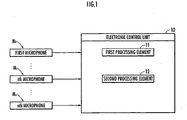
- an electronic control unit an electronic circuit such as a CPU, a ROM, a RAM, an I/O circuit or an A/D conversion circuit 10.
- the electronic control unit 10 separates a plurality of sound source signals on the basis of input signals from the plurality of microphones M i .
- the electronic control unit 10 includes a first processing element 11 and a second processing element 12.
- the first processing element 11 and the second processing element 12 may be composed of the same CPU or different CPUs.
- the first processing element 11 is defined by a separation matrix W representing independency between the input signals from the microphones M 1 and the sound source signals and realizes a cost function J(W) for evaluating the separation degree of the sound source signals.
- the second processing element 12 performs a process of deciding a next separation matrix W k+1 by updating a current separation matrix W k such that a next value J(W k+1 ) of the cost function realized by the first processing element 11 be closer to a minimum value J(W 0 ) than a current value J(W k ).
- the second processing element 12 iteratively performs this process so as to realize a separation matrix when the cost function becomes the minimum value, as an optimal separation matrix W 0 .
- the second processing element 12 adjusts an update amount ⁇ W k from the current separation matrix W k to the next separation matrix W k+1 by the current value J(W k ) of the cost function and a current gradient ⁇ J(W k )/ ⁇ W.
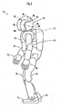
- the microphones M i are provided at the left and right sides of a head portion P1 of a robot R, in which the electronic control unit 10 is mounted, four by four, as shown in Fig. 2 .
- the microphones M 1 to M 4 are provided at a front upper part, a rear upper part, a front lower part, and a rear lower part of the right side of the head portion P1.
- the microphones M 5 to M 8 are provided at a front upper part, a rear upper part, a front lower part, and a rear lower part of the left side of the head portion P1.
- the sound source separation system may be mounted in any machine or device in an environment in which a plurality of sound sources exist, such as a vehicle (four-wheel vehicle), in addition to the robot R.
- the robot R is a legged mobile robot and includes a base body P0, the head portion P1 provided above the base body P0, left and right arm portions P2 which extend from the both sides of the upper part of the base body P0, hand portions P3 connected to the front ends of the left and right arm portions P2, left and right leg portions P4 which extend downward from the lower part of the base body P0, and foot portions P5 connected to the left and right leg portions P4, similar to a human.
- the base body P0 is composed of an upper part and a lower part which are vertically connected so as to be rotated relative to each other by rotation of a yawing axis.
- the head portion P1 is rotated or moved by the rotation of the yawing axis with respect to the base body P0.
- Each of the arm portions P2 has a rotation freedom degree of uniaxial to triaxial rotation in a shoulder joint mechanism, an elbow joint mechanism and a carpus joint mechanism
- each of the hand portions P3 includes five finger mechanisms which extend from a hand palm portion and corresponds to a thumb, an index finger, a middle finger, a third finger and a little finger of the human and can perform an object holding action.
- Each of the leg portions P4 has a rotation freedom degree of uniaxial to triaxial rotation in a hip joint mechanism, a knee mechanism and an ankle joint mechanism.
- the robot R can perform a proper action, that is, the movement of the left and right leg portions P4, on the basis of the sound source separation result.
- the function of the sound source separation system having the above-described configuration will be described.
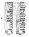
- the index k representing the number of times of update of the separation matrix W is set to "1" ( Fig. 3 /S001) and the input signals from the microphones M i are acquired by the electronic control unit 10 ( Fig. 3 /S002).
- the cost function J(W) for evaluating the separation degree of the sound source signals are defined or realized by the first processing element 11 ( Fig. 3 /S004 (see Equations (4) and (5)).
- a current update amount W k of the separation matrix is adjusted by an adaptive step-size (AS) method ( Fig. 3 /S008).
- AS adaptive step-size
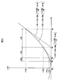
- the cost function J(W) in the vicinity of the current value J(W k ) of the cost function is linearly approximated as expressed by Equation (16) according to the complex gradient calculating method.
- the cost function J(W) varies according to the separation matrix W
- the cost function J(W) is approximated as a linear function (see an alternate long and short dashes line, an alternate long and two short dashed line, and an alternate long and three short dashes line) sloped by the current gradient ⁇ J(W k )/ ⁇ W of the cost function J(W) via the current value J(W k ) of the cost function.
- the optimal current step-size parameter ⁇ k is expressed by Equation (17).
- the current update amount ⁇ W k of the separation matrix W is decided by ⁇ k J'(W k ).
- ⁇ k J W k / 2 ⁇ MA ⁇ J W k / ⁇ W , J ⁇ W k
- the AS method may be applied to various BSSs.
- DSS-AS Adaptive step-size DSS
- Equation (101) to (105) An algorithm in which the present method is applied to the DSS is defined by Equations (101) to (105).
- ICA-AS Adaptive step-size ICA
- HDSS-AS Adaptive step-size higher-order DSS
- Equation (301) to (305) An algorithm in which the present method is applied to the higher-order DSS is defined by Equations (301) to (305).
- GSS-AS Adaptive step-size GSS
- y W k ⁇ x
- An algorithm in which the present method is applied to the GHDDS is defined by replacing a cost function E SS expressed by Equation (402) of Equations (401) to (408) defining the GSS-AS with a cost function E ICA expressed by Equation (502) defining the GICA-AS.
- a deviation norm (Frobenius norm) between the next separation matrix W k+1 and the optimal separation matrix W 0 is less than an allowable value eps ( Fig. 3 /S012). If the result of determination is No ( Fig. 3 /S012 ... NO), the index k is increased by "1" by the second processing element 12 ( Fig. 3 /S014), and the acquisition of the input signals from the microphones, the evaluation of the cost function J(W), the adjustment of the update amount ⁇ W k and the processing of the next separation matrix W k+1 are performed again ( Fig. 3 /see S002, S004, S008, S010 and S012). In contrast, if the result of determination is Yes ( Fig.
- the next separation matrix W is decided as the optimal separation matrix W 0 ( Fig. 3 /S016).
- a process of updating the current separation matrix W k to the next separation matrix W k+1 is iteratively performed such that the next value J(W k+1 ) of the cost function becomes closer to the minimum value than the current value J(W k ) ( Fig. 3 /S008, S010, S012 and S014, see the arrow of Fig. 4 ).
- the update amount ⁇ W k of the separation matrix W is adjusted to be increased as the current value J(W k ) of the cost function is increased and is adjusted to be decreased as the current gradient ⁇ J(W k )/ ⁇ W of the cost function is increased (see Fig. 4 ).
- the update amount ⁇ W k of the separation matrix is adjusted to be properly increased from the viewpoint of the improvement of a convergence rate.
- the update amount ⁇ W k of the separation matrix is adjusted to be properly increased from the viewpoint of the improvement of the convergence rate similar to the first state and the update amount ⁇ W k of the separation matrix is adjusted to be further decreased than the first state from the viewpoint of the improvement of the convergence precision.
- the update amount ⁇ W k of the separation matrix is adjusted to be properly decreased from the viewpoint of the improvement of the convergence precision.
- the update amount ⁇ W k of the separation matrix is adjusted to be properly decreased from the viewpoint of the improvement of the convergence precision similar to the third state and the update amount ⁇ W k of the separation matrix is adjusted to be further increased than the third state from the viewpoint of the improvement of the convergence rate.
- the input signals x i (t) of the microphones M i are synthesized as expressed by Equation (18) on the basis of an impulse response h ji (t) from a j th sound source to the microphones M i , a sound source signal s j (t) of the j th sound source, and the background noise n i (t) of the microphones M i .
- x i t ⁇ j ⁇ h ji t ⁇ s j t + n i t
- the sound source signal s j (t) two clean voices were used as the sound source signal s j (t).
- a male voice as a first sound source signal shown in Fig. 5(a)
- a female voice as a second source signal shown in Fig. 5(b) were used.
- the impulse response h ji (t) an actual measurement value of an experimental laboratory was adopted.
- the size of the experimental laboratory has a vertical length of 4.0 [m], a horizontal length of 7.0 [m] and a height of 3.0 [m], and an echo time is about 0.2 [s].
- One surface of the walls of the experimental laboratory is made of glass and generates strong reflection.
- n i (t) an actual measurement value shown in Fig. 5(c) of the experimental laboratory was employed.
- Fig. 5(d) the synthesized input signal x i (t) is shown.
- Fig. 6 shows the frequency characteristics of the signals.
- the background noise has a level lower than that of the sound source by about -10 to -20 dB.
- the separation result was evaluated on the basis of a separation result signal y, a noise signal n # included in the signal y, a separation result signal s # of the input signal when only a target sound source exists, and a SNR calculated according to Equation (19). This indicates that the sound source is separated at higher precision as the SNR is increased.
- the separation matrix W was initiated according to Equation (21) using a transfer function matrix D having a transfer function of a direct sound component as an element.
- W DS Diag D H ⁇ D - 1 ⁇ D H
- the separation matrix W may be initiated according to Equation (22) or (23) instead of Equation (21).
- W DS indicates that the coefficient of a minimum norm weighted delay sum BF is used as an initial value and W NULL indicates that the coefficient of a null BF is used as an initial value. Since W NULL has a higher initial separation degree than W DS but has low robustness for a variation, an initial value in which W DS has higher performance is given if echo is strong or a geometric information error is large.
- a scaling problem is solved by normalizing the sizes of row vectors of the separation matrix.
- a permutation problem is considered to be solved by the initial value and a supplementary process is omitted.
- a normalization coefficient ⁇ necessary for the conventional geometric constrained BBS was " ⁇ x H x ⁇ -2 " in the GSS and the GHDSS according to Document 12 and was "1" because normalization is made in a natural gradient in the GICA.
- a non-linear function ⁇ (y i ) used in the methods other than the DSS was defined by Equation (24) on the basis of a scaling parameter ⁇ (which is "1" in the present experiment).
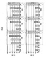
- the SNR of the separated sound source signal in the case where the step-size parameter ⁇ is "0.001", “0.01” and "0.1" and the case where the AS method is applied is shown in Fig. 7
- the CC of the sound source signal is shown in Fig. 8
- the waveforms separated according to the GSS-AS are shown in Fig. 9 .
- the SNR was significantly improved by the AS.
- an average SNR was improved.
- the correlation coefficient CC is about -3 dB, but, according to the AS, is about -7 dB or more in all the BSSs. It can be seen that the AS is efficient in non-correlation. The cause that the SNR of the GSS and the HDSS is not significantly improved by the AS is a geometric constraint error.
- the step-size parameter ⁇ and the update amount ⁇ W k from the current value W k of the separation matrix to the next value W k+1 are increased as the current value J(W k ) of the cost function is increased.
- All methods of dynamically adjusting the step-size parameter and the update amount to be decreased as the current gradient ⁇ J(Wk)/ ⁇ W of the cost function is increased may be employed inasmuch as falling within the scope of the appended claims.
Landscapes
- Engineering & Computer Science (AREA)
- Computer Vision & Pattern Recognition (AREA)
- Data Mining & Analysis (AREA)
- Theoretical Computer Science (AREA)
- Physics & Mathematics (AREA)
- General Engineering & Computer Science (AREA)
- Bioinformatics & Computational Biology (AREA)
- Evolutionary Biology (AREA)
- Evolutionary Computation (AREA)
- Bioinformatics & Cheminformatics (AREA)
- Artificial Intelligence (AREA)
- General Physics & Mathematics (AREA)
- Life Sciences & Earth Sciences (AREA)
- Quality & Reliability (AREA)
- Computational Linguistics (AREA)
- Signal Processing (AREA)
- Health & Medical Sciences (AREA)
- Audiology, Speech & Language Pathology (AREA)
- Human Computer Interaction (AREA)
- Acoustics & Sound (AREA)
- Multimedia (AREA)
- Circuit For Audible Band Transducer (AREA)
Claims (2)
- Système de séparation de sources sonores pour séparer une pluralité de sources sonores sur la base de signaux d'entrée provenant de la pluralité de microphones qu'il comprend, le système comprenant également :un premier élément de traitement réalisant une fonction de coût pour évaluer les degrés de séparation des signaux de sources sonores, la fonction de coût étant basée sur une matrice de séparation représentant l'interdépendance entre les signaux d'entrée et les signaux de sources sonores ; etun second élément de traitement qui réalise une matrice de séparation optimale, qui est la matrice de séparation lorsque la fonction de coût devient une valeur minimale, en réalisant de manière itérative un processus d'actualisation d'une matrice de séparation courante, de telle sorte qu'une valeur suivante de la fonction de coût réalisée par le premier élément de traitement se rapproche davantage de la valeur minimale qu'une valeur courante de façon à décider d'une matrice de séparation suivante, et ajuste une quantité d'actualisation de la matrice de séparation courante à la matrice de séparation suivante, la quantité d'actualisation étant liée à la valeur courante de la fonction de coût et liée inversement au gradient courant de la fonction de coût, de telle sorte que la quantité d'actualisation soit plus grande quand la valeur de la fonction de coût est élevée, et plus faible quand la valeur de la fonction de coût est basse, et que la quantité d'actualisation soit plus faible quand le gradient de la fonction de coût est élevé, et plus grande quand le gradient de la fonction de coût est bas.
- Système de séparation de sources sonores selon la revendication 1, dans lequel le second élément de traitement ajuste la quantité d'actualisation de la matrice de séparation selon un procédé de Newton multidimensionnel, de telle sorte que la matrice de séparation actualisée produise une valeur nulle dans une approximation linéaire de la fonction de coût autour de la matrice de séparation courante.
Applications Claiming Priority (2)
| Application Number | Priority Date | Filing Date | Title |
|---|---|---|---|
| US94279907P | 2007-06-08 | 2007-06-08 | |
| JP2008133175A JP4444345B2 (ja) | 2007-06-08 | 2008-05-21 | 音源分離システム |
Publications (2)
| Publication Number | Publication Date |
|---|---|
| EP2012307A1 EP2012307A1 (fr) | 2009-01-07 |
| EP2012307B1 true EP2012307B1 (fr) | 2009-12-30 |
Family
ID=39684101
Family Applications (1)
| Application Number | Title | Priority Date | Filing Date |
|---|---|---|---|
| EP08251991A Active EP2012307B1 (fr) | 2007-06-08 | 2008-06-09 | Système de séparation de sources sonores |
Country Status (2)
| Country | Link |
|---|---|
| US (1) | US8131542B2 (fr) |
| EP (1) | EP2012307B1 (fr) |
Families Citing this family (9)
| Publication number | Priority date | Publication date | Assignee | Title |
|---|---|---|---|---|
| US8583428B2 (en) | 2010-06-15 | 2013-11-12 | Microsoft Corporation | Sound source separation using spatial filtering and regularization phases |
| JP5706782B2 (ja) * | 2010-08-17 | 2015-04-22 | 本田技研工業株式会社 | 音源分離装置及び音源分離方法 |
| US9100734B2 (en) | 2010-10-22 | 2015-08-04 | Qualcomm Incorporated | Systems, methods, apparatus, and computer-readable media for far-field multi-source tracking and separation |
| KR101726737B1 (ko) * | 2010-12-14 | 2017-04-13 | 삼성전자주식회사 | 다채널 음원 분리 장치 및 그 방법 |
| EP2600343A1 (fr) * | 2011-12-02 | 2013-06-05 | Fraunhofer-Gesellschaft zur Förderung der angewandten Forschung e.V. | Appareil et procédé pour flux de codage audio spatial basé sur la géométrie de fusion |
| CN110088834B (zh) * | 2016-12-23 | 2023-10-27 | 辛纳普蒂克斯公司 | 用于语音去混响的多输入多输出(mimo)音频信号处理 |
| JP6730177B2 (ja) * | 2016-12-28 | 2020-07-29 | 株式会社デンソーテン | 画像生成装置および画像生成方法 |
| FR3067511A1 (fr) * | 2017-06-09 | 2018-12-14 | Orange | Traitement de donnees sonores pour une separation de sources sonores dans un signal multicanal |
| JP7235534B6 (ja) * | 2019-02-27 | 2024-02-08 | 本田技研工業株式会社 | マイクロホンアレイ位置推定装置、マイクロホンアレイ位置推定方法、およびプログラム |
Family Cites Families (7)
| Publication number | Priority date | Publication date | Assignee | Title |
|---|---|---|---|---|
| US6898612B1 (en) * | 1998-11-12 | 2005-05-24 | Sarnoff Corporation | Method and system for on-line blind source separation |
| SE521024C2 (sv) * | 1999-03-08 | 2003-09-23 | Ericsson Telefon Ab L M | Metod och anordning för att separera en blandning av källsignaler |
| JP3725418B2 (ja) * | 2000-11-01 | 2005-12-14 | インターナショナル・ビジネス・マシーンズ・コーポレーション | 複数信号が混合される画像データから多次元信号を復元する信号分離方法、画像処理装置および記憶媒体 |
| US7076433B2 (en) * | 2001-01-24 | 2006-07-11 | Honda Giken Kogyo Kabushiki Kaisha | Apparatus and program for separating a desired sound from a mixed input sound |
| JP3950930B2 (ja) * | 2002-05-10 | 2007-08-01 | 財団法人北九州産業学術推進機構 | 音源の位置情報を利用した分割スペクトルに基づく目的音声の復元方法 |
| US7496482B2 (en) * | 2003-09-02 | 2009-02-24 | Nippon Telegraph And Telephone Corporation | Signal separation method, signal separation device and recording medium |
| AU2003291862A1 (en) | 2003-12-01 | 2005-06-24 | Aic | A highly optimized method for modelling a windowed signal |
-
2008
- 2008-06-05 US US12/133,691 patent/US8131542B2/en active Active
- 2008-06-09 EP EP08251991A patent/EP2012307B1/fr active Active
Also Published As
| Publication number | Publication date |
|---|---|
| US20080306739A1 (en) | 2008-12-11 |
| EP2012307A1 (fr) | 2009-01-07 |
| US8131542B2 (en) | 2012-03-06 |
Similar Documents
| Publication | Publication Date | Title |
|---|---|---|
| EP2012307B1 (fr) | Système de séparation de sources sonores | |
| CN100559472C (zh) | 语音信号分离设备和方法 | |
| US6622117B2 (en) | EM algorithm for convolutive independent component analysis (CICA) | |
| US9668066B1 (en) | Blind source separation systems | |
| CN1855227B (zh) | 用于分离音频信号的装置和方法 | |
| US8867755B2 (en) | Sound source separation apparatus and sound source separation method | |
| US8898056B2 (en) | System and method for generating a separated signal by reordering frequency components | |
| US5754681A (en) | Signal pattern recognition apparatus comprising parameter training controller for training feature conversion parameters and discriminant functions | |
| CN104573738B (zh) | 信号处理方法及其装置 | |
| WO2005083706A1 (fr) | Procedes et appareil de separation aveugle de melanges convolutifs multicanaux dans le domaine de frequence | |
| CN104737229A (zh) | 用于变换输入信号的方法 | |
| JP5911101B2 (ja) | 音響信号解析装置、方法、及びプログラム | |
| JP4444345B2 (ja) | 音源分離システム | |
| EP2023343A1 (fr) | Système de séparation de source sonore | |
| CN109116338B (zh) | 一种基于四阶累积量的宽带凸优化doa估计方法 | |
| Das et al. | ICA methods for blind source separation of instantaneous mixtures: A case study | |
| WO2015048070A1 (fr) | Traitement directionnel temps-fréquence de signaux audio | |
| Miao | Filtered Krylov-like sequence method for symmetric eigenvalue problems | |
| Mitianoudis | Audio source separation using independent component analysis | |
| JP4946330B2 (ja) | 信号分離装置及び方法 | |
| JP4738284B2 (ja) | ブラインド信号抽出装置、その方法、そのプログラム、及びそのプログラムを記録した記録媒体 | |
| CN108322858B (zh) | 基于张量分解的多麦克风语音增强方法 | |
| Wang et al. | Sparsity promoted non-negative matrix factorization for source separation and detection | |
| Wang et al. | Determined Blind Source Separation with Sinkhorn Divergence-based Optimal Allocation of the Source Power | |
| Chibole | Blind Signal Processing (BSP) of Two-Input Two-Output Linear System for separating Audio Signals using Independent Component Analysis applied in Natural Gradient Algorithm |
Legal Events
| Date | Code | Title | Description |
|---|---|---|---|
| PUAI | Public reference made under article 153(3) epc to a published international application that has entered the european phase |
Free format text: ORIGINAL CODE: 0009012 |
|
| 17P | Request for examination filed |
Effective date: 20080630 |
|
| AK | Designated contracting states |
Kind code of ref document: A1 Designated state(s): AT BE BG CH CY CZ DE DK EE ES FI FR GB GR HR HU IE IS IT LI LT LU LV MC MT NL NO PL PT RO SE SI SK TR |
|
| AX | Request for extension of the european patent |
Extension state: AL BA MK RS |
|
| GRAP | Despatch of communication of intention to grant a patent |
Free format text: ORIGINAL CODE: EPIDOSNIGR1 |
|
| GRAS | Grant fee paid |
Free format text: ORIGINAL CODE: EPIDOSNIGR3 |
|
| AKX | Designation fees paid |
Designated state(s): DE FR GB |
|
| GRAA | (expected) grant |
Free format text: ORIGINAL CODE: 0009210 |
|
| AK | Designated contracting states |
Kind code of ref document: B1 Designated state(s): DE FR GB |
|
| REG | Reference to a national code |
Ref country code: GB Ref legal event code: FG4D |
|
| REF | Corresponds to: |
Ref document number: 602008000475 Country of ref document: DE Date of ref document: 20100211 Kind code of ref document: P |
|
| PLBE | No opposition filed within time limit |
Free format text: ORIGINAL CODE: 0009261 |
|
| STAA | Information on the status of an ep patent application or granted ep patent |
Free format text: STATUS: NO OPPOSITION FILED WITHIN TIME LIMIT |
|
| 26N | No opposition filed |
Effective date: 20101001 |
|
| PGFP | Annual fee paid to national office [announced via postgrant information from national office to epo] |
Ref country code: FR Payment date: 20110621 Year of fee payment: 4 |
|
| GBPC | Gb: european patent ceased through non-payment of renewal fee |
Effective date: 20120609 |
|
| REG | Reference to a national code |
Ref country code: FR Ref legal event code: ST Effective date: 20130228 |
|
| PG25 | Lapsed in a contracting state [announced via postgrant information from national office to epo] |
Ref country code: FR Free format text: LAPSE BECAUSE OF NON-PAYMENT OF DUE FEES Effective date: 20120702 Ref country code: GB Free format text: LAPSE BECAUSE OF NON-PAYMENT OF DUE FEES Effective date: 20120609 |
|
| PGFP | Annual fee paid to national office [announced via postgrant information from national office to epo] |
Ref country code: DE Payment date: 20250520 Year of fee payment: 18 |