EP2012144A1 - Grille lumineuse et procédé destiné au fonctionnement d'une grille lumineuse - Google Patents
Grille lumineuse et procédé destiné au fonctionnement d'une grille lumineuse Download PDFInfo
- Publication number
- EP2012144A1 EP2012144A1 EP07013194A EP07013194A EP2012144A1 EP 2012144 A1 EP2012144 A1 EP 2012144A1 EP 07013194 A EP07013194 A EP 07013194A EP 07013194 A EP07013194 A EP 07013194A EP 2012144 A1 EP2012144 A1 EP 2012144A1
- Authority
- EP
- European Patent Office
- Prior art keywords
- units
- transmitting
- receiving
- group
- unit
- Prior art date
- Legal status (The legal status is an assumption and is not a legal conclusion. Google has not performed a legal analysis and makes no representation as to the accuracy of the status listed.)
- Granted
Links
- 238000000034 method Methods 0.000 title claims abstract description 10
- 238000012360 testing method Methods 0.000 claims abstract description 12
- 230000005540 biological transmission Effects 0.000 claims description 18
- 238000001208 nuclear magnetic resonance pulse sequence Methods 0.000 claims description 14
- 230000002596 correlated effect Effects 0.000 claims description 7
- 238000011156 evaluation Methods 0.000 claims description 5
- 230000004044 response Effects 0.000 claims description 5
- 238000004891 communication Methods 0.000 claims description 3
- 230000005693 optoelectronics Effects 0.000 claims description 3
- 230000004913 activation Effects 0.000 claims description 2
- 230000001276 controlling effect Effects 0.000 claims 1
- 230000000875 corresponding effect Effects 0.000 description 8
- 230000001960 triggered effect Effects 0.000 description 6
- 230000002950 deficient Effects 0.000 description 2
- 238000005516 engineering process Methods 0.000 description 2
- 230000002452 interceptive effect Effects 0.000 description 2
- 230000009467 reduction Effects 0.000 description 2
- 230000002829 reductive effect Effects 0.000 description 2
- 230000001629 suppression Effects 0.000 description 2
- 230000003213 activating effect Effects 0.000 description 1
- 230000002238 attenuated effect Effects 0.000 description 1
- 230000001419 dependent effect Effects 0.000 description 1
- 238000001514 detection method Methods 0.000 description 1
- 231100001261 hazardous Toxicity 0.000 description 1
- 230000000670 limiting effect Effects 0.000 description 1
- 238000011089 mechanical engineering Methods 0.000 description 1
- 238000012986 modification Methods 0.000 description 1
- 230000004048 modification Effects 0.000 description 1
- 238000004806 packaging method and process Methods 0.000 description 1
- 230000036961 partial effect Effects 0.000 description 1
- 230000008569 process Effects 0.000 description 1
- 230000000717 retained effect Effects 0.000 description 1
Images
Classifications
-
- G—PHYSICS
- G01—MEASURING; TESTING
- G01V—GEOPHYSICS; GRAVITATIONAL MEASUREMENTS; DETECTING MASSES OR OBJECTS; TAGS
- G01V8/00—Prospecting or detecting by optical means
- G01V8/10—Detecting, e.g. by using light barriers
- G01V8/20—Detecting, e.g. by using light barriers using multiple transmitters or receivers
Definitions
- the invention relates to a light grid according to the preamble of patent claim 1 and a method for operating a light grid according to the preamble of patent claim 8.
- Applications are e.g. the safeguarding of access to automatic production facilities, the protection of access openings to production cells, the protection of press brakes and palletizing systems, transport technology, conveyor and warehouse technology, the packaging industry, mechanical engineering and the automotive industry.
- a safety function is triggered, e.g. an alarm is triggered, a hazardous production machine switched off or the like.
- the detection of an object in the light grid is based on the fact that there is a reduction of the energy input into a given receiving unit, because the object in the light beam shadows the receiving unit.
- the resolution of a light grid indicates the size of the smallest object, which is still reliably detected by the light grid.
- the resolution becomes better as the size of the smallest securely detected object becomes smaller.
- the resolution considered above is an energy resolution, it is determined by the reduction of the energy input into a receiving unit by the object.
- the resolution of a light grid is usually worse than the diameter of a light beam; Instead, it is customary to specify the distance between the mutually remote outer sides of two receiving units as the resolution of the light grid.
- the invention is based on the finding that, by means of an arrangement in which at least one group of at least one transmitting unit and at least one group of at least one receiving unit are arranged alternately on each of the strips bordering the monitored passage, a group of at least one receiving unit the one strip is in each case opposite at least one transmitting unit on the other strip and a group of at least one transmitting unit on the one bar opposite at least one receiving unit on the other bar, the problem of Störlichteinträge a given transmitting unit is defused in a receiving unit adjacent to the receiving unit.
- Opasite shall mean the following: By a given group of transmitting or receiving units on one of the bars, the area on this bar is defined, in which these transmitting or receiving units are arranged. A receiving or transmitting unit located somewhere in the area of the second strip corresponding to this area on the first strip then faces this group. The correspondence between areas on the two strips results, for example, by their spatial arrangement; for example, by being equidistant from a reference plane, e.g. the ground, are spaced.
- the device comprises transmitting units, receiving units as well as a first strip and a second strip, which together define the passage to be monitored and on, on or in which the transmitting and receiving units are arranged, and a control and evaluation circuit, which controls the transmission and reception units, for the readout of receiving units, for checking whether the light energy radiated into a receiving unit or a group of receiving units meets a switching condition and to trigger a safety function, if not the case, is designed.
- the transmitting units and the receiving units are arranged on the first bar and on the second bar, that are arranged alternately arranged on each of the monitored passage limiting strips at least one group of at least one transmitting unit and at least one group of at least one receiving unit a group of at least one receiving unit on the first or second bar each opposite at least one transmitting unit on the second or first bar and a group of at least one transmitting unit on the first or second bar at least one receiving unit on the second or first bar is opposite.
- the groups of transmitting units each consist of exactly one transmitting unit and the groups of receiving units each consist of exactly one receiving unit.
- a particularly advantageous alternative embodiment of the invention with regard to the suppression of interfering signals and the costs of the arrangement provides that the groups of transmitting units are larger than the groups of receiving units or the groups of receiving units are larger than the groups of transmitting units. This lowers the cost of materials for producing the light grid by preferentially using the less expensive components of the transmitter unit and receiver unit and further increases the spatial distance between groups of receiver units on a given bar, thereby interfering with a given group of transmitter units on a non-associated group of receiver units is reduced.
- the time required for a scan is shortened when a plurality of transmitting units grouped in one group emit light in parallel and are discriminated and recognized by the receiver by a factor corresponding to the inverse of the number of parallel beams.
- the suppression of interference signals can be further optimized by a preferred arrangement in which the respective smaller of the groups of transmitting units or receiving units is arranged so that its center is opposite to the center of the larger of the groups of receiving units or transmitting units.
- pulse sequence is to be construed broadly and in particular not to be restricted to ideally orthogonal pulse sequences, since ideal orthogonality is not attainable under real conditions, meaning, in particular, the realizable quasi-orthogonal pulse sequences.
- a further advantageous embodiment of the invention provides means for performing a test scan, during which it is ensured that no object is located in the light grid and thus no shading can be present. This can ensure that the receiving units are operated in a linear response range.
- the method according to the invention for operating a light grid comprises the steps of activating receiver units and transmitter units, comparing the energy input into the groups of receiver units formed from at least one receiver unit with a threshold value, triggering a safety function if the value of the energy input is formed in the at least one receiver unit Groups of receiving units below the threshold, wherein pairs, consisting of a group of at least one receiving unit on the first or second bar and a group of at least one transmitting unit, which are located on the second and first bar, are formed and at least two adjacent so formed pairs of Groups of transmitting units and receiver units are controlled and read out simultaneously.
- the transmitting units which are combined in a group, transmit light cones in correlated pulse sequences which are orthogonal to the correlated pulse sequences used in the light cones of the other transmitting units located in this group, the correlated pulse sequences being different from those in can be assigned to a group associated associated receiving units via correlation of a given transmitting unit.
- Orthogonal are two sequences of light pulses, each forming a cone of light, when they have no or no significant correlation with each other. This broad definition of the term "orthogonal" is necessary, since in reality or under real conditions ideal orthogonality of consequences of light pulses can hardly be achieved.
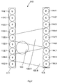
- FIG. 2 shows a light grid 110 according to the prior art.
- the light grid 110 has a first strip 111 and a second strip 113.
- On the first bar 111 transmitting units 112.1 to 112.9 are arranged.
- On the second bar 113 receiving units 114.1 to 114.9 are arranged. Not shown is the control and evaluation, which is necessary for the operation of such a light grid 110.
- the transmitting units 112.1 to 112.9 send, if they are controlled by the control electronics, light beams, which due to the in the FIG. 2 for the transmitting units 112.5, 112.8 example shown exaggerated divergence to light cones 122.5, 122.8 are expanded.
- the light grid 110 is an object 120, the extent of which corresponds precisely to the resolution of the light grid 110.
- pairs of transmitting and receiving units 112.1 and 114.1, 112.2 and 114.2, 112.3 and 114.3, 112.4 and 114.4, 112.5 and 114.5, 112.6 and 114.6, 112.7 and 114.7, 112.8 and 114.8, 112.9 and 114.9 are required to be individually accessed and / or evaluated. If, in fact, the transmitting units 112.1 to 112.9 and the receiving units 114.1 to 114.9 were operated simultaneously, the object 120 would not be detected in the light grid 110.
- this object 120 prevents direct energy input from the transmitting unit 112.6 into the receiving unit 114.6 and direct energy input from the transmitting unit 112.7 into the receiving unit 114.7, due to the divergence of the light cone 122.5 or 122.8 emitted by the transmitting units 112.5 or 112.8, however, it does occur nevertheless to an energy input in the receiving units 114.6 and 114.7, so that the switching threshold is not exceeded and falsely the safety function is not triggered, although an object 120 is in the light grid 110.
- the pairs of transmitting units and receiving units 112.1 and 114.1, 112.2 and 114.2, 112.3 and 114.3, 112.4 and 114.4, 112.5 and 114.5, 112.6 and 114.6, 112.7 and 114.7, 112.8 and 114.8, 112.9 and 114.9 each individually operated with a time delay.
- the article 120 is reliably detected.
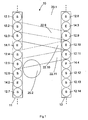
- FIG. 1 shows a light grid 10 according to an embodiment of the present invention.
- FIG. 1 are sections of a first bar 11 and a second bar 13 shown.
- the transmitting units 12.1 to 12.14 are arranged partly on the first strip 11 and partly on the second strip 13. This is followed by a group of three transmitting units 12.1, 12.2, 12.3; 12.4, 12.5, 12.6; 12.9, 12.10, 12.11; 12.12, 12.13, 12.14, one group each of a receiving unit 14.1; 14.2; 14.3; 14.4.
- FIG. 1 only a section of the first bar 11 and the second bar 13 is shown, the entire sequence is continued in the same arrangement principle above and below the pictured sections of the strips 11 and 13.
- triggered transmitter units 12.1-12.14 emit light beams which are widened as a result of the divergence shown exaggeratedly into light cones 22.9, 22.10, 22.11.
- the center of the light cone of each transmitting unit 12.1 to 12.14 is directed to the respective opposite transmitting or receiving unit
- the center of the light cone 22.9 is aligned with the transmitting unit 12.9 opposite transmitting unit 12.3
- the center of the light cone 22.10 is aligned with the transmitting unit 12.10 opposite receiving unit 12.4
- the center of the light cone 22.11 is aligned with the transmitting unit 12.11 opposite transmitting unit 12.4.
- FIG. 1 it can be seen directly that in this arrangement it is no longer possible to influence a receiving unit, for example 14.2, 14.3 or 14.4, assigned to a given group of transmitting units, for example 12.9, 12.10 and 12.11, because of the divergence of the light cones 22.9 to 22.11 ,
- the transmitting units 12.1 to 12.14 in such a way that at least the respective groups belonging to a group of transmitting units 12.1, 12.2, 12.3; 12.9, 12.10, 12.11; 12.4, 12.5, 12.6; 12.12, 12.13, 12.14 emitted as light signals each mutually orthogonal pulse sequences and the receiving unit 14.1, 14.2, 14.3, 14.4 is designed so that it is able to keep apart the pulse trains on correlation and assign the respective transmitting unit 12.1 to 12.14 ,
- the light output registered in a given receiving unit 14.1 to 14.4 can be determined. If there is an at least partial shadowing of the receiving unit 14.1 to 14.4 or of a group of transmitting units 12.9, 12.10, 12.11 assigned to the receiving unit 14.1 to 14.4; 12/12, 12.13, 12.14; 12.1, 12.2, 12.3; 12.4, 12.5, 12.6, the energy input in the respective receiving unit 14.1, 14.2, 14.3, 14.4 is correspondingly reduced and the safety function is triggered.
- a test scan is carried out in which it is ensured that no object 20.1, 20.2 is located in the light grid 10.
- the values determined in this way can be stored in the evaluation unit and correlated with the respective current values for the corresponding energy entries.
- the receiving units 14.1 to 14.4 operate in the linear range. This would also be the case if instead of individual receiving units 14.1 to 14.4 groups of receiving units were used.
- the information can be obtained in a test scan with which transmission power the transmission units 12.1 to 12.14 are to be operated in order to ensure this.
- the transmitting units 12.1 to 12.14 are assigned by their receiving unit 14.1; 14.2; 14.3; 14.4 are identifiable, which, for example, by means of a special, the respective transmitting unit 12.1 to 12.14 associated pulse sequence or single operation of belonging to a group transmitting units 12.9, 12.10, 12.11; 12.12, 12.13, 12.14; 12.1, 12.2, 12.3; 12.4, 12.5, 12.6 can be clearly or at least identified with a very high degree of certainty whether a transmitting unit 12.1 to 12.14 or a receiving unit 14.1 to 14.4 is defective.
- the receiving unit is defective; at least one of the transmission units of the group 12.1, 12.2, 12.3; 12.4, 12.5, 12.6; 12.9, 12.10, 12.11; 12.12, 12.13, 12.14, it is the unrecognized transmitting units.
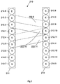
- FIG. 3 Another embodiment of a light grid 210 according to this invention shows FIG. 3 , In FIG. 3 are contrary to FIG. 1 not only sections of a first bar 211 and a second bar 213 shown, but the entire bars 211 and 213th
- transmitting units 212.2 to 212.13 and receiving units 214.1 to 214.6 are arranged partly on the first bar 11 and partly on the second bar 13.
- a group of two transmission units 212.2, 212.3, then a group from a reception unit 214.1, the next group of transmission units 212.4, 212.5, 12.6, followed by a further group from one follows on the first bar 211 on a group from a reception unit 214.6
- Receiving unit 214.2 and a last group from a transmitting unit 212.7 is arranged with a group of two transmission units 212.2, 212.3, then a group from a reception unit 214.1, the next group of transmission units 212.4, 212.5, 12.6, followed by a further group from one follows on the first bar 211 on a group from a reception unit 214.6
- Receiving unit 214.2 and a last group from a transmitting unit 212.7 is arranged partly on the first bar 11 and partly on the second bar 13.
- On the second bar 213 is the Arrangement of groups a group of a transmitting unit 212.8, a group of a receiving unit 214.3, a group of three transmitting units 212.9, 212.10, 212.11, a group of a receiving unit 214.4, a group of two transmitting units 212.12, 212.13 and a group of a receiving unit 214.5 , Also shown are light beams 222.9, 222.10, 222.11 radiated by the transmission units 212.9, 212.10 or 212.11 by way of example.
- the receiving unit 214.3 faces the group of transmitting units 212.2, 213.2.
- the "desired entry" of light power for the individual groups of receiving units 214.1; 214.2; 214.3; 214.4; 214.5; 214.6 to determine individually, as in unabgeschattetem state groups from different numbers of transmitting units 212.2-212.13 radiate light power into a given receiving unit 214.1-214.6.
- This can be done again with the help of a test scan; of course, corresponding means for storing the values of the "desired entry” into the groups of receiving units 214.1; 214.2; 214.3; 214.4; 214.5; 214.6 be provided.
Landscapes
- Physics & Mathematics (AREA)
- Life Sciences & Earth Sciences (AREA)
- General Life Sciences & Earth Sciences (AREA)
- General Physics & Mathematics (AREA)
- Geophysics (AREA)
- Geophysics And Detection Of Objects (AREA)
- Operating, Guiding And Securing Of Roll- Type Closing Members (AREA)
- Photometry And Measurement Of Optical Pulse Characteristics (AREA)
- Optical Communication System (AREA)
Priority Applications (2)
| Application Number | Priority Date | Filing Date | Title |
|---|---|---|---|
| EP07013194A EP2012144B1 (fr) | 2007-07-05 | 2007-07-05 | Grille lumineuse et procédé destiné au fonctionnement d'une grille lumineuse |
| AT07013194T ATE541227T1 (de) | 2007-07-05 | 2007-07-05 | Lichtgitter und verfahren zum betrieb eines lichtgitters |
Applications Claiming Priority (1)
| Application Number | Priority Date | Filing Date | Title |
|---|---|---|---|
| EP07013194A EP2012144B1 (fr) | 2007-07-05 | 2007-07-05 | Grille lumineuse et procédé destiné au fonctionnement d'une grille lumineuse |
Publications (2)
| Publication Number | Publication Date |
|---|---|
| EP2012144A1 true EP2012144A1 (fr) | 2009-01-07 |
| EP2012144B1 EP2012144B1 (fr) | 2012-01-11 |
Family
ID=39079436
Family Applications (1)
| Application Number | Title | Priority Date | Filing Date |
|---|---|---|---|
| EP07013194A Not-in-force EP2012144B1 (fr) | 2007-07-05 | 2007-07-05 | Grille lumineuse et procédé destiné au fonctionnement d'une grille lumineuse |
Country Status (2)
| Country | Link |
|---|---|
| EP (1) | EP2012144B1 (fr) |
| AT (1) | ATE541227T1 (fr) |
Cited By (7)
| Publication number | Priority date | Publication date | Assignee | Title |
|---|---|---|---|---|
| DE202008001122U1 (de) * | 2008-01-25 | 2009-06-18 | Marantec Antriebs- Und Steuerungstechnik Gmbh & Co. Kg | Lichtschranke |
| DE102009009386A1 (de) * | 2009-02-18 | 2010-09-23 | Leuze Electronic Gmbh & Co Kg | Optoelektronische Vorrichtung |
| EP2312340A1 (fr) | 2009-10-08 | 2011-04-20 | Sick Ag | Procédé de fonctionnement d'un capteur optoélectronique et capteur optoélectronique |
| EP2610647A1 (fr) | 2011-12-27 | 2013-07-03 | Sick AG | Capteur optoélectronique |
| DE102007031430B4 (de) * | 2007-07-05 | 2016-12-01 | Sick Ag | Verfahren zum Betrieb eines Lichtgitters und Lichtgitter |
| CN109959973A (zh) * | 2017-12-14 | 2019-07-02 | 埃利斯塔有限公司,奥斯特菲尔登(德国),巴特拉加茨分公司 | 用于运行光栅组件的方法 |
| DE102018108340A1 (de) | 2018-04-09 | 2019-10-10 | Sick Ag | Optoelektronischer Sensor und Verfahren zur Erfassung und Abstandsbestimmung von Objekten |
Families Citing this family (2)
| Publication number | Priority date | Publication date | Assignee | Title |
|---|---|---|---|---|
| IT201700109596A1 (it) | 2017-09-29 | 2019-03-29 | Omron Tateisi Electronics Co | Metodo per il funzionamento di una barriera di sicurezza e barriera di sicurezza. |
| EP4166993B1 (fr) * | 2021-10-18 | 2024-08-07 | Pepperl+Fuchs SE | Capteur pour la provision d'une région de surveillance |
Citations (7)
| Publication number | Priority date | Publication date | Assignee | Title |
|---|---|---|---|---|
| DE2648631A1 (de) * | 1976-10-27 | 1978-05-03 | Licentia Gmbh | Lichtelektrische schranke mit paaren von lichtelektrischen sendern und empfaengern |
| EP0388352A1 (fr) * | 1989-03-15 | 1990-09-19 | Elesta Ag Elektronik | Dispositif pour barrière optique à une seule direction |
| DE19541410A1 (de) * | 1995-11-07 | 1997-05-15 | O & K Rolltreppen Gmbh | Wiederbereitschaftsschalteinrichtung für Personenförderanlagen |
| DE19611195C1 (de) * | 1996-03-21 | 1997-06-05 | Lumiflex Elektronik Gmbh & Co | Verfahren zum Betrieb einer Lichtschrankenanordnung |
| US6130437A (en) * | 1998-04-24 | 2000-10-10 | Hama Sensors, Inc. | Sensor and detection system having wide diverging beam optics |
| DE10120940A1 (de) * | 2001-04-20 | 2002-10-24 | Fiessler Elektronik Ohg | Sicherheitseinrichtung zur Überwachung von mindestens zwei aneinandergrenzenden Ebenen durch Lichtschrankenanordnungen, insbesondere Lichtvorhänge |
| EP1296161A2 (fr) * | 2001-09-21 | 2003-03-26 | Sick Ag | Barrière optique à séparateur de faisceaux |
-
2007
- 2007-07-05 EP EP07013194A patent/EP2012144B1/fr not_active Not-in-force
- 2007-07-05 AT AT07013194T patent/ATE541227T1/de active
Patent Citations (7)
| Publication number | Priority date | Publication date | Assignee | Title |
|---|---|---|---|---|
| DE2648631A1 (de) * | 1976-10-27 | 1978-05-03 | Licentia Gmbh | Lichtelektrische schranke mit paaren von lichtelektrischen sendern und empfaengern |
| EP0388352A1 (fr) * | 1989-03-15 | 1990-09-19 | Elesta Ag Elektronik | Dispositif pour barrière optique à une seule direction |
| DE19541410A1 (de) * | 1995-11-07 | 1997-05-15 | O & K Rolltreppen Gmbh | Wiederbereitschaftsschalteinrichtung für Personenförderanlagen |
| DE19611195C1 (de) * | 1996-03-21 | 1997-06-05 | Lumiflex Elektronik Gmbh & Co | Verfahren zum Betrieb einer Lichtschrankenanordnung |
| US6130437A (en) * | 1998-04-24 | 2000-10-10 | Hama Sensors, Inc. | Sensor and detection system having wide diverging beam optics |
| DE10120940A1 (de) * | 2001-04-20 | 2002-10-24 | Fiessler Elektronik Ohg | Sicherheitseinrichtung zur Überwachung von mindestens zwei aneinandergrenzenden Ebenen durch Lichtschrankenanordnungen, insbesondere Lichtvorhänge |
| EP1296161A2 (fr) * | 2001-09-21 | 2003-03-26 | Sick Ag | Barrière optique à séparateur de faisceaux |
Cited By (9)
| Publication number | Priority date | Publication date | Assignee | Title |
|---|---|---|---|---|
| DE102007031430B4 (de) * | 2007-07-05 | 2016-12-01 | Sick Ag | Verfahren zum Betrieb eines Lichtgitters und Lichtgitter |
| DE202008001122U1 (de) * | 2008-01-25 | 2009-06-18 | Marantec Antriebs- Und Steuerungstechnik Gmbh & Co. Kg | Lichtschranke |
| US7973273B2 (en) | 2008-01-25 | 2011-07-05 | Marantec Antriebs—und Steuerungstechnik GmbH & Co. KG | Light barrier with feedback control |
| DE102009009386A1 (de) * | 2009-02-18 | 2010-09-23 | Leuze Electronic Gmbh & Co Kg | Optoelektronische Vorrichtung |
| DE102009009386B4 (de) * | 2009-02-18 | 2011-01-27 | Leuze Electronic Gmbh & Co Kg | Optoelektronische Vorrichtung |
| EP2312340A1 (fr) | 2009-10-08 | 2011-04-20 | Sick Ag | Procédé de fonctionnement d'un capteur optoélectronique et capteur optoélectronique |
| EP2610647A1 (fr) | 2011-12-27 | 2013-07-03 | Sick AG | Capteur optoélectronique |
| CN109959973A (zh) * | 2017-12-14 | 2019-07-02 | 埃利斯塔有限公司,奥斯特菲尔登(德国),巴特拉加茨分公司 | 用于运行光栅组件的方法 |
| DE102018108340A1 (de) | 2018-04-09 | 2019-10-10 | Sick Ag | Optoelektronischer Sensor und Verfahren zur Erfassung und Abstandsbestimmung von Objekten |
Also Published As
| Publication number | Publication date |
|---|---|
| ATE541227T1 (de) | 2012-01-15 |
| EP2012144B1 (fr) | 2012-01-11 |
Similar Documents
| Publication | Publication Date | Title |
|---|---|---|
| EP2012144B1 (fr) | Grille lumineuse et procédé destiné au fonctionnement d'une grille lumineuse | |
| EP1544643B1 (fr) | Procédé et dispositif pour la surveillance d'une zone avec plusieurs émetteurs de lumière disposés côte à côte | |
| EP2492714B1 (fr) | Procédé de fonctionnement d'une barrière lumineuse de sécurité et barrière lumineuse de sécurité | |
| EP3069202B2 (fr) | Commande de sécurité à entrées configurables | |
| EP1933174B1 (fr) | Barrière lumineuse | |
| EP2071363B1 (fr) | Barrière lumineuse et son procédé de fonctionnement | |
| DE102007024210A1 (de) | Optoelektronischer Sensor zum Absichern eines Gefahrenbereichs | |
| EP2362242B1 (fr) | Capteur optoélectronique | |
| DE102006012537B4 (de) | Lichtgitter | |
| EP0066200A1 (fr) | Procédé et dispositif pour la révision dans un système détecteur de danger et particulièrement d'incendie | |
| DE102007031430B4 (de) | Verfahren zum Betrieb eines Lichtgitters und Lichtgitter | |
| DE102016005854A1 (de) | Vorrichtung und Verfahren zur Überwachung eines Schutzbereichs | |
| DE202007004442U1 (de) | Vorrichtung zur Reichweitenerhöhung eines Lichtgitters | |
| EP1391752B1 (fr) | Grille de lumière | |
| DE69622106T2 (de) | Verfahren und vorrichtung zur überwachung von ventileinheiten | |
| EP2463687B1 (fr) | Capteur optoélectronique | |
| DE102008022791C5 (de) | Lichtvorhang | |
| EP4092449B1 (fr) | Agencement de barrière lumineuse et procédé de détection des objets dans une zone de surveillance | |
| DE3728354C2 (fr) | ||
| DE202018104258U1 (de) | Sicherheitslichtgitter | |
| DE102005047776B4 (de) | Verfahren zum Betrieb eines Lichtgitters | |
| EP2259093B1 (fr) | Dispositif de capteur optoélectronique et procédé de fonctionnement d'un tel dispositif | |
| DE2827863C2 (fr) | ||
| DE102009056848B3 (de) | Verfahren zur Absicherung eines Gefahrenbereichs einer Maschine und zur Erkennung von Objekten | |
| EP2487512B1 (fr) | Procédé destiné au fonctionnement d'une grille lumineuse et grille lumineuse |
Legal Events
| Date | Code | Title | Description |
|---|---|---|---|
| PUAI | Public reference made under article 153(3) epc to a published international application that has entered the european phase |
Free format text: ORIGINAL CODE: 0009012 |
|
| 17P | Request for examination filed |
Effective date: 20081017 |
|
| AK | Designated contracting states |
Kind code of ref document: A1 Designated state(s): AT BE BG CH CY CZ DE DK EE ES FI FR GB GR HU IE IS IT LI LT LU LV MC MT NL PL PT RO SE SI SK TR |
|
| AX | Request for extension of the european patent |
Extension state: AL BA HR MK RS |
|
| AKX | Designation fees paid |
Designated state(s): AT BE BG CH CY CZ DE DK EE ES FI FR GB GR HU IE IS IT LI LT LU LV MC MT NL PL PT RO SE SI SK TR |
|
| GRAP | Despatch of communication of intention to grant a patent |
Free format text: ORIGINAL CODE: EPIDOSNIGR1 |
|
| GRAS | Grant fee paid |
Free format text: ORIGINAL CODE: EPIDOSNIGR3 |
|
| GRAA | (expected) grant |
Free format text: ORIGINAL CODE: 0009210 |
|
| AK | Designated contracting states |
Kind code of ref document: B1 Designated state(s): AT BE BG CH CY CZ DE DK EE ES FI FR GB GR HU IE IS IT LI LT LU LV MC MT NL PL PT RO SE SI SK TR |
|
| REG | Reference to a national code |
Ref country code: GB Ref legal event code: FG4D Free format text: NOT ENGLISH |
|
| REG | Reference to a national code |
Ref country code: CH Ref legal event code: EP |
|
| REG | Reference to a national code |
Ref country code: AT Ref legal event code: REF Ref document number: 541227 Country of ref document: AT Kind code of ref document: T Effective date: 20120115 |
|
| REG | Reference to a national code |
Ref country code: IE Ref legal event code: FG4D |
|
| REG | Reference to a national code |
Ref country code: DE Ref legal event code: R096 Ref document number: 502007009024 Country of ref document: DE Effective date: 20120315 |
|
| REG | Reference to a national code |
Ref country code: NL Ref legal event code: VDEP Effective date: 20120111 |
|
| PG25 | Lapsed in a contracting state [announced via postgrant information from national office to epo] |
Ref country code: SI Free format text: LAPSE BECAUSE OF FAILURE TO SUBMIT A TRANSLATION OF THE DESCRIPTION OR TO PAY THE FEE WITHIN THE PRESCRIBED TIME-LIMIT Effective date: 20120111 |
|
| LTIE | Lt: invalidation of european patent or patent extension |
Effective date: 20120111 |
|
| PG25 | Lapsed in a contracting state [announced via postgrant information from national office to epo] |
Ref country code: NL Free format text: LAPSE BECAUSE OF FAILURE TO SUBMIT A TRANSLATION OF THE DESCRIPTION OR TO PAY THE FEE WITHIN THE PRESCRIBED TIME-LIMIT Effective date: 20120111 Ref country code: LT Free format text: LAPSE BECAUSE OF FAILURE TO SUBMIT A TRANSLATION OF THE DESCRIPTION OR TO PAY THE FEE WITHIN THE PRESCRIBED TIME-LIMIT Effective date: 20120111 Ref country code: IS Free format text: LAPSE BECAUSE OF FAILURE TO SUBMIT A TRANSLATION OF THE DESCRIPTION OR TO PAY THE FEE WITHIN THE PRESCRIBED TIME-LIMIT Effective date: 20120511 Ref country code: BG Free format text: LAPSE BECAUSE OF FAILURE TO SUBMIT A TRANSLATION OF THE DESCRIPTION OR TO PAY THE FEE WITHIN THE PRESCRIBED TIME-LIMIT Effective date: 20120411 |
|
| REG | Reference to a national code |
Ref country code: IE Ref legal event code: FD4D |
|
| PG25 | Lapsed in a contracting state [announced via postgrant information from national office to epo] |
Ref country code: LV Free format text: LAPSE BECAUSE OF FAILURE TO SUBMIT A TRANSLATION OF THE DESCRIPTION OR TO PAY THE FEE WITHIN THE PRESCRIBED TIME-LIMIT Effective date: 20120111 Ref country code: GR Free format text: LAPSE BECAUSE OF FAILURE TO SUBMIT A TRANSLATION OF THE DESCRIPTION OR TO PAY THE FEE WITHIN THE PRESCRIBED TIME-LIMIT Effective date: 20120412 Ref country code: PT Free format text: LAPSE BECAUSE OF FAILURE TO SUBMIT A TRANSLATION OF THE DESCRIPTION OR TO PAY THE FEE WITHIN THE PRESCRIBED TIME-LIMIT Effective date: 20120511 Ref country code: PL Free format text: LAPSE BECAUSE OF FAILURE TO SUBMIT A TRANSLATION OF THE DESCRIPTION OR TO PAY THE FEE WITHIN THE PRESCRIBED TIME-LIMIT Effective date: 20120111 Ref country code: FI Free format text: LAPSE BECAUSE OF FAILURE TO SUBMIT A TRANSLATION OF THE DESCRIPTION OR TO PAY THE FEE WITHIN THE PRESCRIBED TIME-LIMIT Effective date: 20120111 |
|
| PG25 | Lapsed in a contracting state [announced via postgrant information from national office to epo] |
Ref country code: CY Free format text: LAPSE BECAUSE OF FAILURE TO SUBMIT A TRANSLATION OF THE DESCRIPTION OR TO PAY THE FEE WITHIN THE PRESCRIBED TIME-LIMIT Effective date: 20120111 |
|
| PG25 | Lapsed in a contracting state [announced via postgrant information from national office to epo] |
Ref country code: DK Free format text: LAPSE BECAUSE OF FAILURE TO SUBMIT A TRANSLATION OF THE DESCRIPTION OR TO PAY THE FEE WITHIN THE PRESCRIBED TIME-LIMIT Effective date: 20120111 Ref country code: CZ Free format text: LAPSE BECAUSE OF FAILURE TO SUBMIT A TRANSLATION OF THE DESCRIPTION OR TO PAY THE FEE WITHIN THE PRESCRIBED TIME-LIMIT Effective date: 20120111 Ref country code: SE Free format text: LAPSE BECAUSE OF FAILURE TO SUBMIT A TRANSLATION OF THE DESCRIPTION OR TO PAY THE FEE WITHIN THE PRESCRIBED TIME-LIMIT Effective date: 20120111 Ref country code: EE Free format text: LAPSE BECAUSE OF FAILURE TO SUBMIT A TRANSLATION OF THE DESCRIPTION OR TO PAY THE FEE WITHIN THE PRESCRIBED TIME-LIMIT Effective date: 20120111 Ref country code: RO Free format text: LAPSE BECAUSE OF FAILURE TO SUBMIT A TRANSLATION OF THE DESCRIPTION OR TO PAY THE FEE WITHIN THE PRESCRIBED TIME-LIMIT Effective date: 20120111 Ref country code: IE Free format text: LAPSE BECAUSE OF FAILURE TO SUBMIT A TRANSLATION OF THE DESCRIPTION OR TO PAY THE FEE WITHIN THE PRESCRIBED TIME-LIMIT Effective date: 20120111 |
|
| PLBE | No opposition filed within time limit |
Free format text: ORIGINAL CODE: 0009261 |
|
| STAA | Information on the status of an ep patent application or granted ep patent |
Free format text: STATUS: NO OPPOSITION FILED WITHIN TIME LIMIT |
|
| PG25 | Lapsed in a contracting state [announced via postgrant information from national office to epo] |
Ref country code: IT Free format text: LAPSE BECAUSE OF FAILURE TO SUBMIT A TRANSLATION OF THE DESCRIPTION OR TO PAY THE FEE WITHIN THE PRESCRIBED TIME-LIMIT Effective date: 20120111 Ref country code: SK Free format text: LAPSE BECAUSE OF FAILURE TO SUBMIT A TRANSLATION OF THE DESCRIPTION OR TO PAY THE FEE WITHIN THE PRESCRIBED TIME-LIMIT Effective date: 20120111 |
|
| 26N | No opposition filed |
Effective date: 20121012 |
|
| BERE | Be: lapsed |
Owner name: SICK A.G. Effective date: 20120731 |
|
| REG | Reference to a national code |
Ref country code: DE Ref legal event code: R097 Ref document number: 502007009024 Country of ref document: DE Effective date: 20121012 |
|
| PG25 | Lapsed in a contracting state [announced via postgrant information from national office to epo] |
Ref country code: MC Free format text: LAPSE BECAUSE OF NON-PAYMENT OF DUE FEES Effective date: 20120731 |
|
| PG25 | Lapsed in a contracting state [announced via postgrant information from national office to epo] |
Ref country code: ES Free format text: LAPSE BECAUSE OF FAILURE TO SUBMIT A TRANSLATION OF THE DESCRIPTION OR TO PAY THE FEE WITHIN THE PRESCRIBED TIME-LIMIT Effective date: 20120422 |
|
| PG25 | Lapsed in a contracting state [announced via postgrant information from national office to epo] |
Ref country code: BE Free format text: LAPSE BECAUSE OF NON-PAYMENT OF DUE FEES Effective date: 20120731 |
|
| PG25 | Lapsed in a contracting state [announced via postgrant information from national office to epo] |
Ref country code: MT Free format text: LAPSE BECAUSE OF FAILURE TO SUBMIT A TRANSLATION OF THE DESCRIPTION OR TO PAY THE FEE WITHIN THE PRESCRIBED TIME-LIMIT Effective date: 20120111 |
|
| REG | Reference to a national code |
Ref country code: AT Ref legal event code: MM01 Ref document number: 541227 Country of ref document: AT Kind code of ref document: T Effective date: 20120731 |
|
| PG25 | Lapsed in a contracting state [announced via postgrant information from national office to epo] |
Ref country code: AT Free format text: LAPSE BECAUSE OF NON-PAYMENT OF DUE FEES Effective date: 20120731 |
|
| PG25 | Lapsed in a contracting state [announced via postgrant information from national office to epo] |
Ref country code: TR Free format text: LAPSE BECAUSE OF FAILURE TO SUBMIT A TRANSLATION OF THE DESCRIPTION OR TO PAY THE FEE WITHIN THE PRESCRIBED TIME-LIMIT Effective date: 20120111 |
|
| PG25 | Lapsed in a contracting state [announced via postgrant information from national office to epo] |
Ref country code: LU Free format text: LAPSE BECAUSE OF NON-PAYMENT OF DUE FEES Effective date: 20120705 |
|
| PG25 | Lapsed in a contracting state [announced via postgrant information from national office to epo] |
Ref country code: HU Free format text: LAPSE BECAUSE OF FAILURE TO SUBMIT A TRANSLATION OF THE DESCRIPTION OR TO PAY THE FEE WITHIN THE PRESCRIBED TIME-LIMIT Effective date: 20070705 |
|
| REG | Reference to a national code |
Ref country code: FR Ref legal event code: PLFP Year of fee payment: 9 |
|
| REG | Reference to a national code |
Ref country code: FR Ref legal event code: PLFP Year of fee payment: 10 |
|
| PGFP | Annual fee paid to national office [announced via postgrant information from national office to epo] |
Ref country code: GB Payment date: 20160722 Year of fee payment: 10 |
|
| REG | Reference to a national code |
Ref country code: FR Ref legal event code: PLFP Year of fee payment: 11 |
|
| GBPC | Gb: european patent ceased through non-payment of renewal fee |
Effective date: 20170705 |
|
| PG25 | Lapsed in a contracting state [announced via postgrant information from national office to epo] |
Ref country code: GB Free format text: LAPSE BECAUSE OF NON-PAYMENT OF DUE FEES Effective date: 20170705 |
|
| REG | Reference to a national code |
Ref country code: FR Ref legal event code: PLFP Year of fee payment: 12 |
|
| PGFP | Annual fee paid to national office [announced via postgrant information from national office to epo] |
Ref country code: IT Payment date: 20180823 Year of fee payment: 14 |
|
| PGFP | Annual fee paid to national office [announced via postgrant information from national office to epo] |
Ref country code: DE Payment date: 20190723 Year of fee payment: 13 |
|
| PGFP | Annual fee paid to national office [announced via postgrant information from national office to epo] |
Ref country code: CH Payment date: 20190725 Year of fee payment: 13 |
|
| PG25 | Lapsed in a contracting state [announced via postgrant information from national office to epo] |
Ref country code: FR Free format text: LAPSE BECAUSE OF NON-PAYMENT OF DUE FEES Effective date: 20190731 |
|
| REG | Reference to a national code |
Ref country code: DE Ref legal event code: R119 Ref document number: 502007009024 Country of ref document: DE |
|
| REG | Reference to a national code |
Ref country code: CH Ref legal event code: PL |
|
| PG25 | Lapsed in a contracting state [announced via postgrant information from national office to epo] |
Ref country code: CH Free format text: LAPSE BECAUSE OF NON-PAYMENT OF DUE FEES Effective date: 20200731 Ref country code: LI Free format text: LAPSE BECAUSE OF NON-PAYMENT OF DUE FEES Effective date: 20200731 |
|
| PG25 | Lapsed in a contracting state [announced via postgrant information from national office to epo] |
Ref country code: DE Free format text: LAPSE BECAUSE OF NON-PAYMENT OF DUE FEES Effective date: 20210202 |