EP2011893A2 - Asymmetrische gradierte Verbundwerkstoffe für verbesserte Bohrmeißel - Google Patents
Asymmetrische gradierte Verbundwerkstoffe für verbesserte Bohrmeißel Download PDFInfo
- Publication number
- EP2011893A2 EP2011893A2 EP08167176A EP08167176A EP2011893A2 EP 2011893 A2 EP2011893 A2 EP 2011893A2 EP 08167176 A EP08167176 A EP 08167176A EP 08167176 A EP08167176 A EP 08167176A EP 2011893 A2 EP2011893 A2 EP 2011893A2
- Authority
- EP
- European Patent Office
- Prior art keywords
- cutting tool
- cutting
- insert
- tungsten carbide
- localized
- Prior art date
- Legal status (The legal status is an assumption and is not a legal conclusion. Google has not performed a legal analysis and makes no representation as to the accuracy of the status listed.)
- Withdrawn
Links
Images




Classifications
-
- E—FIXED CONSTRUCTIONS
- E21—EARTH OR ROCK DRILLING; MINING
- E21B—EARTH OR ROCK DRILLING; OBTAINING OIL, GAS, WATER, SOLUBLE OR MELTABLE MATERIALS OR A SLURRY OF MINERALS FROM WELLS
- E21B10/00—Drill bits
- E21B10/46—Drill bits characterised by wear resisting parts, e.g. diamond inserts
- E21B10/56—Button-type inserts
-
- C—CHEMISTRY; METALLURGY
- C23—COATING METALLIC MATERIAL; COATING MATERIAL WITH METALLIC MATERIAL; CHEMICAL SURFACE TREATMENT; DIFFUSION TREATMENT OF METALLIC MATERIAL; COATING BY VACUUM EVAPORATION, BY SPUTTERING, BY ION IMPLANTATION OR BY CHEMICAL VAPOUR DEPOSITION, IN GENERAL; INHIBITING CORROSION OF METALLIC MATERIAL OR INCRUSTATION IN GENERAL
- C23C—COATING METALLIC MATERIAL; COATING MATERIAL WITH METALLIC MATERIAL; SURFACE TREATMENT OF METALLIC MATERIAL BY DIFFUSION INTO THE SURFACE, BY CHEMICAL CONVERSION OR SUBSTITUTION; COATING BY VACUUM EVAPORATION, BY SPUTTERING, BY ION IMPLANTATION OR BY CHEMICAL VAPOUR DEPOSITION, IN GENERAL
- C23C30/00—Coating with metallic material characterised only by the composition of the metallic material, i.e. not characterised by the coating process
- C23C30/005—Coating with metallic material characterised only by the composition of the metallic material, i.e. not characterised by the coating process on hard metal substrates
Definitions
- the invention relates generally to methods for providing improved drill bits.
- the present invention relates to methods for generating localized and/or asymmetrically graded compositions in cutting elements.
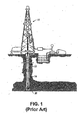
- FIG. 1 shows one example of a conventional drilling system drilling an earth formation.
- the drilling system includes a drilling rig 10 used to turn a drill string 12, which extends downward into a well bore 14.
- roller cone-type drill bit 20 Connected to the end of the drill string 12 is roller cone-type drill bit 20, shown in further detail in FIG. 2 .
- a roller cone bit 20 typically comprises a bit body 22 having an externally threaded connection at one end 24, and a plurality of roller cones 26 (usually three as shown) attached to the other end of the bit body 22 and able to rotate with respect to the bit body 22.
- Attached to the roller cones 26 of the bit 20 are a plurality of cutting elements 28, typically arranged in rows about the surface of the roller cones 26.
- the cutting elements 28 can be inserts, polycrystalline diamond compacts, or milled steel teeth. If the cutting elements 28 are milled steel teeth, they may be coated with a hardfacing material.
- One particular type of insert uses tungsten carbide and thus are known as TCI.
- tungsten carbides Many different types are known based on their different chemical compositions and physical structure. Three types of tungsten carbide commonly used in manufacturing drill bits are cast tungsten carbide, macro-crystalline tungsten carbide, and cemented tungsten carbide (also known as sintered tungsten carbide).
- Cemented carbides as exemplified by WC-Co, have a unique combination of high elastic modulus, high hardness, high compressive strength, and high wear and abrasion resistance with reasonable levels of fracture toughness. See Brookes, Kenneth J.A., "World Directory and Handbook of Hardmetals and Hard Materials,” International Carbide Data, 1997 . This unique combination of properties makes them ideally suited for a variety of industrial applications, such as drill bits. See “ Powder Metal Technologies and Applications, Powder Metallurgy Cermets and Cemented Carbides, section on Cemented Carbides," Metals Handbook, Vol. 7, ASM International, Metals Park, Ohio, 1998, pp. 933-937 .
- One aspect of the invention relates to a cutting tool that includes at least one tungsten carbide cutting element disposed on a support, wherein at least one tungsten carbide cutting element has at least one localized region having a material property different from the remaining region, wherein the at least one localized region having a different material property is prepared by a method including determining at least one localized region needing a variation in a material property different from the remaining region; coating a portion of a surface of the at least one tungsten carbide cutting element with a refractory material such that a surface corresponding to the localized region is left uncoated; and treating the coated cutting element with a selected agent to diffuse the selected agent into the localized region.
- a cutting tool that includes at least one gage element disposed on a support, wherein at least one gage element has at least one localized region having a material property different from the remaining region, wherein the at least one localized region having a different material property is prepared by a method including determining at least one localized region needing a variation in a material property different from the remaining region; coating a portion of a surface of the at least one tungsten carbide cutting element with a refractory material such that a surface corresponding to the localized region is left uncoated; and treating the coated cutting element with a selected agent to diffuse the selected agent into the localized region.
- Yet another aspect of the invention relates to a method that includes determining at least one localized region of a tungsten carbide cutting element needing a variation in a material property different from the remaining region; coating at least one area on a surface of the tungsten carbide cutting element with a refractory material, wherein the coating leaves at least one uncoated area on the surface of the tungsten carbide cutting element; and treating the coated cutting element with a selected agent to diffuse the selected agent into the at least one uncoated area, creating a binder gradient in the tungsten carbide cutting element in the at least one uncoated area.
- FIG. 1 shows an example of a conventional drill system drilling an earth formation.
- FIG. 2 shows a conventional roller cone drill bit.
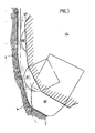
- FIG. 3 shows a roller cone drill bit according to one embodiment disclosed herein.
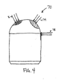
- FIG. 4 shows a schematic of an insert illustrating different regions that are prone to wear and fracture.
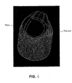
- FIG. 5 shows a schematic of an insert illustrating different regions that are prone to wear and fracture.
- FIGs. 6A and 6B show a side view and a top view of an insert, respectively, illustrating asymmetric load distributions on the insert.
- FIG. 7 shows a chart illustrating binder content changes in a cemented tungsten carbide as an interstitial additive is diffused into it.
- FIG. 8 shows a cemented tungsten carbide having boron diffused into it in accordance with one embodiment of the invention.
- FIG. 9 shows that the refractory material (TiN) successfully prevents boron diffusion into regions coated with it in accordance with one embodiment of the invention.
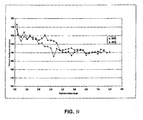
- FIG. 10 shows variations in hardness as a function of variations in boron diffusion as in DyaniteTM cemented carbides.
- FIG. 11 shows a flow chart of a method for producing localized variations in material properties in accordance with one embodiment of the invention.
- Embodiments of the invention relate to methods for producing localized variations in the material properties of inserts (cutting elements). Some embodiments of the invention relate to drill bits that include inserts having localized gradients of material compositions therein, wherein the gradients of material compositions comprising gradients of the binder (e.g., cobalt) in the tungsten carbide. Some embodiments of the invention provide methods for altering material properties of an insert locally and/or asymmetrically by generating areas with variations in the material compositions. Being able to generate localized variations in material properties on an insert is desirable. For example, lower binder content regions may be generated locally (e.g., on the cutting surface of an insert) to have increased wear resistance without significantly lowering fracture toughness.
- the binder e.g., cobalt
- Cone 26 includes a plurality of heel row inserts 60 and gage inserts 70 having base portions secured by interference fit into mating sockets drilled into cone 26, and cutting portions connected to the base portions having cutting surfaces that extend for cutting formation material.
- Cone 26 further includes a plurality of radially-extending, inner row cutting elements 80.
- Heel inserts 60 generally function to scrape or ream the borehole sidewall 5 to maintain the borehole at full gage and prevent erosion and abrasion of heel surface 62.
- Inner row cutting elements 80 are employed primarily to gouge and remove formation material from the borehole bottom 7. Gage inserts 70 and the upper portion of first inner row teeth 80 cooperate to cut the corner 6 of the borehole.
- a gage element 70 may be need to withstand stress 74 related to maintaining the gage diameter in the borehole, stress 76 related to scraping the borehole bottom, and a typical insert protruding bending loads 78.
- the top surface (cutting surface) of an insert may suffer more from wear, while the neck region (the region between the cutting surface and the section held in the insert hole) is more prone to facture.
- This observation suggests that high levels of wear resistance and fracture resistance are not needed throughout an insert, nor are they needed at the same locations on an insert. Therefore, it is inefficient to optimize the composition for the entire insert because that necessarily leads to a compromise between wear resistance and toughness.
- FIGs. 6A (side view) and 6B (top view) which show load distributions on an insert.
- Asymmetric as used herein is with reference to a symmetry element (e.g., a center point, an axis or a plane) of an insert. As shown in FIGs. 6A and 6B , load distributions on this particular insert are asymmetric with respect to the longitudinal axis of the insert.
- Two approaches may be used to produce the desired local variations in the material compositions and properties of an insert.
- the required variations in the material compositions and properties of the insert may be created from the beginning (i.e., using different materials) and preserved throughout the subsequent processing steps.
- an insert may be made of a homogenous material, and the desired local variations in the material properties may be created in a later step.
- Embodiments of the invention belong to the second category.
- DPTM concept noted above, also belongs to the second category, this method subjects an entire insert to recarburization treatment, i.e., the DPTM method cannot produce localized variations in material properties.
- U.S. Patent No. 6,869,460 issued to Bennett et al. discloses a method for creating binder gradients in a carbide article (e.g., an insert). According to the disclosed method, an insert is formed by standard sintering practices, followed by chemical removal of the binder phase from the surface and near surface regions of the insert. The insert is then heat treated at a temperature of 1300-1350° C.
- embodiments of the invention can produce variations in material compositions and properties of an insert in a localized and/or asymmetric manner.
- Embodiments of the invention are based on the observation that generation of binder gradients in cemented tungsten carbides (WC-Co) would produce material property changes in the cemented tungsten carbides, as shown in FIG. 7 , and that binder gradients can be generated by diffusion an interstitial agent (an additive), such as carbon, boron, and nitrogen, into the cemented tungsten carbides.
- an additive such as carbon, boron, and nitrogen
- carbon gradients may be produced by re-carburization of cemented tungsten carbides that may have been intentionally under-carburized.
- cemented tungsten carbides having carbon gradients include the DPTM carbides available from Sandvik AB Corporation (Sandviken, Sweden).
- DPTM carbides are produced by recarburization of cemented tungsten carbides that creates a carbon gradient near the surface. The carbon gradient near the surface results in a binder gradient, leading to property changes in the cemented tungsten carbides.
- nitrogen gradients may be generated, for example, by adding a decomposable nitride to the cemented tungsten carbides.
- the decomposable nitride will produce low nitrogen contents in the cemented tungsten carbides near the surface when heated to high temperatures. This nitrogen gradient in turn produces alloy carbide depletion and binder enrichment near the surface.
- Metal cutting inserts with nitrogen gradients generated near the surfaces have been shown to produce binder-enriched surfaces that have better fracture resistance.
- boron gradients may be introduced into cemented tungsten carbides to provide altered properties.
- Boron gradients can be generated using, for example, boron nitride (BN) in an atmosphere furnace.
- BN boron nitride
- Methods for infusion of boron into cemented carbides can be found, for example, in U.S. Patent Nos. 4,961,780 issued to Pennington, Jr. et al. and 5,116,416 issued to Knox et al .
- An exemplary method disclosed in these two patents includes sintering tungsten carbides in a continuous stoking furnace in a disassociated ammonia atmosphere at 1450 °C for one hour while surrounded by an alumina sand heavily saturated in carbon and including 1% boron nitride.
- Embodiments of the invention are based on a similar concept - creating interstitial gradients to induce binder gradients.
- embodiments of the invention produce localized interstitial gradients, and hence localized binder gradients and localized variations in material properties.
- localized gradients may be created by coating an insert with a diffusion barrier (i.e., a refractory material) in areas where the interstitial composition are to be maintained (i.e., where no gradient is to be created). Then, a selected additive is diffused into the insert in areas not protected by the refractory material (diffusion barrier).
- a diffusion barrier i.e., a refractory material
- a suitable diffusion barrier will depend on the selected additive that is to be used in the diffusion step.
- materials that can withstand the high temperatures required for additive diffusion e.g., sintering temperature for the additive material
- group VI, group V and most group VI transition metal carbides, nitrides, or carbonitrides may be used as refractory materials to coat the inserts and create localized gradients of material properties.
- titanium nitride (TiN) is used as a refractory material, particularly when boron is selected as the additive.
- rectangular bars of WC-Co (3.81 cm x 2.54 cm x 0.64 cm (1.5 inch x 1 inch x 0.25 inch) in size; about 10 wt.% Co) were coated with a refractory material (e.g., TiN) using a suitable method, such as physical vapor deposition (PVD), to a proper thickness (e.g., about 2 ⁇ m) on all sides except one.
- PVD physical vapor deposition
- PVD physical vapor deposition
- a proper thickness e.g., about 2 ⁇ m
- CVD chemical vapor deposition
- particular coating methods may be selected based on the properties of the refractory materials used.
- the coated bars were treated to produce a gradient in boron concentration near the uncoated side.
- the boron treatment may use any method known in the art.
- One example method for the introduction of boron into cemented tungsten carbides is disclosed in U.S. Patent Nos. 4,961,780 and 5,116,416 , noted above. The method disclosed in these patents, as described above, has been used to produce DyaniteTM tungsten carbides, which is a trade name of Credo Co., a part of the Vermont American Corporation (Louisville, KY).
- DyaniteTM is a WC-Co composition modified by addition of boron (B).
- the microstructure of DyaniteTM consists of WC grains distributed in the cobalt (binder) matrix, along with a boron-rich phase containing W, Co, B and carbon (C).
- DyaniteTM has a slightly higher hardness and a substantially increased fracture toughness.
- FIGs. 8 and 9 show The microstructures of the test bars after boron treatment.
- FIG. 8 shows areas on the uncoated sides
- FIG. 9 shows the coated sides.
- the dark areas in FIG. 8 (uncoated sides), shown in 85 includes boron-rich phase that resulted from boron treatment.
- the dark areas are absent on the coated sides ( FIG. 9 ), indicating that the refractory coating (TiN) acted as a diffusion barrier to successfully prevent the diffusion of boron into the coated sides.
- binder gradients in cemented tungsten carbides may be created by generation of gradients of an additive (e.g., C, B, or N). It is known that alteration of binder compositions will result in property changes in the cemented tungsten carbides. For example, significant hardness gradients were previously found in low-cobalt content WC-Co samples that had been DyaniteTM treated, as shown in FIG. 10 . Accordingly, the local concentration gradients in boron, as seen in FIG. 8 , are expected to result in local hardness gradients. Indeed, hardness gradients in boron diffused WC-Co were detected in these samples, albeit not very large (data not shown). The low hardness gradients observed in this example is most likely due to the relatively high cobalt contents in the starting cemented carbide samples because the degree of binder gradient created will be relatively less significant when the starting binder concentration is high.
- an additive e.g., C, B, or N.
- Some embodiments of the invention relate to inserts having localized material property changes. Some embodiments of the invention relate to dill bits having inserts that include local variations in material properties therein.
- the drill bits may be fixed cutter drill bits or roller cone drill bits.
- some embodiments of the invention relate to methods for generating localized (and/or asymmetric) variations in a material property of an insert.
- FIG. 11 shows a method 110 in accordance with one embodiment of the invention for forming localized material property gradient in an insert.
- the areas on an insert in need of altered material properties are determined (shown at 112). This determination may be based on simulation of the insert performance in drilling a selected formation or from prior examination of inserts used in drilling operations. Note that these areas may be asymmetric with respect to an axis or a plane of an insert.
- the other areas may then be coated with a refractory material, such as TiN (shown at 114).
- the insert is subjected to additive diffusion treatments in a suitable process (shown at 116).
- the additive diffusion method will depend on the agent to be diffused. For example, to diffuse boron into cemented tungsten carbides, the method used for the production of the DyaniteTM carbides may be used.
- Embodiments of the present invention may also find use in any downhole cutting application in which there exists potential wear failure.
- the present disclosure refers to inserts of a drill bit
- the localized or asymmetric material composites disclosed herein may be used in a variety of cutting structures or bodies for cutting structures, and in other downhole cutting tools including, for example, reamers, continuous miners, or various types of drill bits including roller cone bits, drag bits.
- cutting tools that may be provided with the localized material compositions and properties disclosed herein are not necessarily limited to tools using in oil and gas exploration, but rather include all types of cutting tools used in drilling and mining.
- embodiments of the present invention provide methods for producing inserts, roller cones or drill bits having localized variations in material properties (hence localized variations in wear resistance and fracture toughness).
- An insert having areas of increased wear resistance and fracture toughness where needed would have an improved performance and life because the insert would not have to compromise the wear resistance with the fracture toughness.
- methods of the invention can provide such variations in material properties in an asymmetric manner; this can further enhance the selective improvement of wear resistance and fracture toughness according to the need of the particular regions.
Landscapes
- Engineering & Computer Science (AREA)
- Chemical & Material Sciences (AREA)
- Geology (AREA)
- Mechanical Engineering (AREA)
- Life Sciences & Earth Sciences (AREA)
- Mining & Mineral Resources (AREA)
- General Life Sciences & Earth Sciences (AREA)
- Fluid Mechanics (AREA)
- Environmental & Geological Engineering (AREA)
- Geochemistry & Mineralogy (AREA)
- Physics & Mathematics (AREA)
- Chemical Kinetics & Catalysis (AREA)
- Materials Engineering (AREA)
- Metallurgy (AREA)
- Organic Chemistry (AREA)
- Cutting Tools, Boring Holders, And Turrets (AREA)
- Drilling Tools (AREA)
- Powder Metallurgy (AREA)
- Earth Drilling (AREA)
Applications Claiming Priority (3)
| Application Number | Priority Date | Filing Date | Title |
|---|---|---|---|
| US69606105P | 2005-07-01 | 2005-07-01 | |
| US11/478,559 US8016056B2 (en) | 2005-07-01 | 2006-06-29 | Asymmetric graded composites for improved drill bits |
| EP06116442A EP1739201B1 (de) | 2005-07-01 | 2006-06-30 | Asymmetrische gradierte Verbundwerkstoffe für verbesserte Bohrmeißel |
Related Parent Applications (1)
| Application Number | Title | Priority Date | Filing Date |
|---|---|---|---|
| EP06116442A Division EP1739201B1 (de) | 2005-07-01 | 2006-06-30 | Asymmetrische gradierte Verbundwerkstoffe für verbesserte Bohrmeißel |
Publications (2)
| Publication Number | Publication Date |
|---|---|
| EP2011893A2 true EP2011893A2 (de) | 2009-01-07 |
| EP2011893A3 EP2011893A3 (de) | 2014-04-09 |
Family
ID=37075202
Family Applications (2)
| Application Number | Title | Priority Date | Filing Date |
|---|---|---|---|
| EP06116442A Not-in-force EP1739201B1 (de) | 2005-07-01 | 2006-06-30 | Asymmetrische gradierte Verbundwerkstoffe für verbesserte Bohrmeißel |
| EP08167176.0A Withdrawn EP2011893A3 (de) | 2005-07-01 | 2006-06-30 | Asymmetrische gradierte Verbundwerkstoffe für verbesserte Bohrmeißel |
Family Applications Before (1)
| Application Number | Title | Priority Date | Filing Date |
|---|---|---|---|
| EP06116442A Not-in-force EP1739201B1 (de) | 2005-07-01 | 2006-06-30 | Asymmetrische gradierte Verbundwerkstoffe für verbesserte Bohrmeißel |
Country Status (5)
| Country | Link |
|---|---|
| US (1) | US8016056B2 (de) |
| EP (2) | EP1739201B1 (de) |
| AU (1) | AU2006202788B2 (de) |
| CA (1) | CA2551389C (de) |
| DE (1) | DE602006003272D1 (de) |
Families Citing this family (10)
| Publication number | Priority date | Publication date | Assignee | Title |
|---|---|---|---|---|
| US9267332B2 (en) * | 2006-11-30 | 2016-02-23 | Longyear Tm, Inc. | Impregnated drilling tools including elongated structures |
| EP2184122A1 (de) | 2008-11-11 | 2010-05-12 | Sandvik Intellectual Property AB | Zementierter Carbidkörper und Verfahren |
| US9187962B2 (en) | 2011-04-26 | 2015-11-17 | Smith International, Inc. | Methods of attaching rolling cutters in fixed cutter bits using sleeve, compression spring, and/or pin(s)/ball(s) |
| WO2012149086A2 (en) | 2011-04-26 | 2012-11-01 | Smith International, Inc. | Polycrystalline diamond compact cutters with conic shaped end |
| US9165756B2 (en) | 2011-06-08 | 2015-10-20 | Xenex Disinfection Services, Llc | Ultraviolet discharge lamp apparatuses with one or more reflectors |
| US9093258B2 (en) | 2011-06-08 | 2015-07-28 | Xenex Disinfection Services, Llc | Ultraviolet discharge lamp apparatuses having optical filters which attenuate visible light |
| US8936114B2 (en) | 2012-01-13 | 2015-01-20 | Halliburton Energy Services, Inc. | Composites comprising clustered reinforcing agents, methods of production, and methods of use |
| US9108301B2 (en) | 2013-03-15 | 2015-08-18 | Diamond Innovations, Inc. | Delayed diffusion of novel species from the back side of carbide |
| US11199051B2 (en) * | 2013-09-04 | 2021-12-14 | Schlumberger Technology Corporation | Cutting elements with wear resistant diamond surface |
| PE20231956A1 (es) | 2016-05-27 | 2023-12-06 | Joy Global Underground Mining Llc | Dispositivo de corte con elemento de corte con seccion decreciente |
Citations (3)
| Publication number | Priority date | Publication date | Assignee | Title |
|---|---|---|---|---|
| US4961780A (en) | 1988-06-29 | 1990-10-09 | Vermont American Corporation | Boron-treated hard metal |
| US5116416A (en) | 1988-03-11 | 1992-05-26 | Vermont American Corporation | Boron-treated hard metal |
| US6869460B1 (en) | 2003-09-22 | 2005-03-22 | Valenite, Llc | Cemented carbide article having binder gradient and process for producing the same |
Family Cites Families (15)
| Publication number | Priority date | Publication date | Assignee | Title |
|---|---|---|---|---|
| US3306381A (en) * | 1963-12-16 | 1967-02-28 | Drilco Oil Tools Inc | Reaming apparatus |
| US4268582A (en) * | 1979-03-02 | 1981-05-19 | General Electric Company | Boride coated cemented carbide |
| US4368788A (en) * | 1980-09-10 | 1983-01-18 | Reed Rock Bit Company | Metal cutting tools utilizing gradient composites |
| EP0111600A1 (de) | 1982-12-13 | 1984-06-27 | Reed Rock Bit Company | Schneidkörper |
| US4934467A (en) * | 1988-12-02 | 1990-06-19 | Dresser Industries, Inc. | Drill bit wear resistant surface for elastomeric seal |
| US5379854A (en) * | 1993-08-17 | 1995-01-10 | Dennis Tool Company | Cutting element for drill bits |
| US5607024A (en) * | 1995-03-07 | 1997-03-04 | Smith International, Inc. | Stability enhanced drill bit and cutting structure having zones of varying wear resistance |
| US5653299A (en) * | 1995-11-17 | 1997-08-05 | Camco International Inc. | Hardmetal facing for rolling cutter drill bit |
| US5752573A (en) * | 1996-08-12 | 1998-05-19 | Baker Hughes Incorporated | Earth-boring bit having shear-cutting elements |
| US6227318B1 (en) | 1998-12-07 | 2001-05-08 | Smith International, Inc. | Superhard material enhanced inserts for earth-boring bits |
| US6241035B1 (en) * | 1998-12-07 | 2001-06-05 | Smith International, Inc. | Superhard material enhanced inserts for earth-boring bits |
| US6227316B1 (en) * | 1999-03-10 | 2001-05-08 | Dresser Industries, Inc. | Jet bit with variable orifice nozzle |
| US6510910B2 (en) * | 2001-02-09 | 2003-01-28 | Smith International, Inc. | Unplanar non-axisymmetric inserts |
| US20060081257A1 (en) * | 2004-08-31 | 2006-04-20 | Ross Krogh | Single use drug delivery components |
| CA2516920A1 (en) | 2004-08-31 | 2006-02-28 | Smith International, Inc. | Maintaining carburized case during neutral to the core heat treatment processes |
-
2006
- 2006-06-29 US US11/478,559 patent/US8016056B2/en not_active Expired - Fee Related
- 2006-06-30 EP EP06116442A patent/EP1739201B1/de not_active Not-in-force
- 2006-06-30 DE DE602006003272T patent/DE602006003272D1/de active Active
- 2006-06-30 CA CA2551389A patent/CA2551389C/en not_active Expired - Fee Related
- 2006-06-30 EP EP08167176.0A patent/EP2011893A3/de not_active Withdrawn
- 2006-06-30 AU AU2006202788A patent/AU2006202788B2/en not_active Ceased
Patent Citations (3)
| Publication number | Priority date | Publication date | Assignee | Title |
|---|---|---|---|---|
| US5116416A (en) | 1988-03-11 | 1992-05-26 | Vermont American Corporation | Boron-treated hard metal |
| US4961780A (en) | 1988-06-29 | 1990-10-09 | Vermont American Corporation | Boron-treated hard metal |
| US6869460B1 (en) | 2003-09-22 | 2005-03-22 | Valenite, Llc | Cemented carbide article having binder gradient and process for producing the same |
Non-Patent Citations (4)
| Title |
|---|
| "Metals Handbook", vol. 7, 1998, ASM INTERNATIONAL, article "Powder Metal Technologies and Applications, Powder Metallurgy Cermets and Cemented Carbides, section on Cemented Carbides", pages: 933 - 937 |
| "Transformation Toughening in Cemented Carbides, II. Themomechanical Treatments", MET. TRANS. A., vol. 18A, 1987, pages 2175 |
| BROOKES, KENNETH J.A.: "International Carbide Data", 1997, article "World Directory and Handbook of Hardmetals and Hard Materials" |
| VISWANADHAM ET AL.: "Transformation Toughening in Cemented Carbides, I. Binder Composition Control", MET. TRANS. A., vol. 18A, 1987, pages 2163 |
Also Published As
| Publication number | Publication date |
|---|---|
| EP2011893A3 (de) | 2014-04-09 |
| EP1739201B1 (de) | 2008-10-22 |
| EP1739201A1 (de) | 2007-01-03 |
| US8016056B2 (en) | 2011-09-13 |
| CA2551389A1 (en) | 2007-01-01 |
| DE602006003272D1 (de) | 2008-12-04 |
| CA2551389C (en) | 2010-12-14 |
| US20070000699A1 (en) | 2007-01-04 |
| AU2006202788B2 (en) | 2009-04-02 |
| AU2006202788A1 (en) | 2007-01-18 |
Similar Documents
| Publication | Publication Date | Title |
|---|---|---|
| EP0182759B1 (de) | Gesinterte Hartmetallegierung zum Gesteinsbohren und zum Schneiden von Mineralien | |
| US9970240B2 (en) | Polycrystalline diamond composite compact | |
| US10456889B2 (en) | Shear cutter with improved wear resistance of WC—Co substrate | |
| US5305840A (en) | Rock bit with cobalt alloy cemented tungsten carbide inserts | |
| RU2503522C2 (ru) | Композитная вставка с поликристаллическими алмазами | |
| EP2324140B1 (de) | Verschleissteil mit harter oberfläche | |
| CN102165081B (zh) | 硬质合金 | |
| US7303030B2 (en) | Barrier coated granules for improved hardfacing material | |
| Konyashin | 1.15 Cemented Carbides for Mining, Construction and Wear Parts | |
| US20130168159A1 (en) | Solid pcd cutter | |
| US8945720B2 (en) | Hard composite with deformable constituent and method of applying to earth-engaging tool | |
| US9353578B2 (en) | Hardfacing compositions, methods of applying the hardfacing compositions, and tools using such hardfacing compositions | |
| US20110042145A1 (en) | Methods for enhancing a surface of a downhole tool and downhole tools having an enhanced surface | |
| CN103946405A (zh) | 钻地用切削镶件和包含其的钻地用钻头 | |
| WO2010080476A2 (en) | Method of designing a bottom hole assembly and a bottom hole assembly | |
| CN104712252A (zh) | 具有高的韧度和高的耐磨性的多晶金刚石材料 | |
| WO2011005403A1 (en) | Wear resistant weld overlay on bearing surfaces in tricone mining rockbits | |
| EP1739201B1 (de) | Asymmetrische gradierte Verbundwerkstoffe für verbesserte Bohrmeißel | |
| GB2470459A (en) | Tungsten carbide based cermets with high thermal conductivities | |
| US20120067651A1 (en) | Hardfacing compositions, methods of applying the hardfacing compositions, and tools using such hardfacing compositions | |
| US7407525B2 (en) | Fracture and wear resistant compounds and down hole cutting tools | |
| US20130168156A1 (en) | Diamond enhanced insert with fine and ultrafine microstructure of pcd working surface resisting crack formation | |
| CA2477673C (en) | Shaped inserts with increased retention force |
Legal Events
| Date | Code | Title | Description |
|---|---|---|---|
| PUAI | Public reference made under article 153(3) epc to a published international application that has entered the european phase |
Free format text: ORIGINAL CODE: 0009012 |
|
| AC | Divisional application: reference to earlier application |
Ref document number: 1739201 Country of ref document: EP Kind code of ref document: P |
|
| AK | Designated contracting states |
Kind code of ref document: A2 Designated state(s): AT BE BG CH CY CZ DE DK EE ES FI FR GB GR HU IE IS IT LI LT LU LV MC NL PL PT RO SE SI SK TR |
|
| AX | Request for extension of the european patent |
Extension state: AL BA HR MK RS |
|
| RIN1 | Information on inventor provided before grant (corrected) |
Inventor name: LOCKWOOD, GREGORY T. Inventor name: LIANG, DAH-BEN Inventor name: VISWANADHAM, RAMAMURTHY |
|
| RTI1 | Title (correction) |
Free format text: ASYMMETRIC GRADED COMPOSITES FOR IMPROVED DRILL BITS |
|
| RAP1 | Party data changed (applicant data changed or rights of an application transferred) |
Owner name: SANDVIK INTELLECTUAL PROPERTY AB |
|
| PUAL | Search report despatched |
Free format text: ORIGINAL CODE: 0009013 |
|
| AK | Designated contracting states |
Kind code of ref document: A3 Designated state(s): DE FI FR GB IT SE |
|
| RIC1 | Information provided on ipc code assigned before grant |
Ipc: C23C 30/00 20060101AFI20140228BHEP Ipc: E21B 10/56 20060101ALI20140228BHEP |
|
| 17P | Request for examination filed |
Effective date: 20141009 |
|
| RBV | Designated contracting states (corrected) |
Designated state(s): DE FI FR GB IT SE |
|
| AKX | Designation fees paid |
Designated state(s): DE FI FR GB IT SE |
|
| STAA | Information on the status of an ep patent application or granted ep patent |
Free format text: STATUS: THE APPLICATION IS DEEMED TO BE WITHDRAWN |
|
| 18D | Application deemed to be withdrawn |
Effective date: 20141010 |