EP2011719A2 - Vehicle floor structure for a motor vehicle - Google Patents
Vehicle floor structure for a motor vehicle Download PDFInfo
- Publication number
- EP2011719A2 EP2011719A2 EP08011591A EP08011591A EP2011719A2 EP 2011719 A2 EP2011719 A2 EP 2011719A2 EP 08011591 A EP08011591 A EP 08011591A EP 08011591 A EP08011591 A EP 08011591A EP 2011719 A2 EP2011719 A2 EP 2011719A2
- Authority
- EP
- European Patent Office
- Prior art keywords
- cross member
- vehicle
- longitudinal
- reinforcement element
- top wall
- Prior art date
- Legal status (The legal status is an assumption and is not a legal conclusion. Google has not performed a legal analysis and makes no representation as to the accuracy of the status listed.)
- Granted
Links
Images


Classifications
-
- B—PERFORMING OPERATIONS; TRANSPORTING
- B62—LAND VEHICLES FOR TRAVELLING OTHERWISE THAN ON RAILS
- B62D—MOTOR VEHICLES; TRAILERS
- B62D21/00—Understructures, i.e. chassis frame on which a vehicle body may be mounted
- B62D21/15—Understructures, i.e. chassis frame on which a vehicle body may be mounted having impact absorbing means, e.g. a frame designed to permanently or temporarily change shape or dimension upon impact with another body
- B62D21/157—Understructures, i.e. chassis frame on which a vehicle body may be mounted having impact absorbing means, e.g. a frame designed to permanently or temporarily change shape or dimension upon impact with another body for side impacts
-
- B—PERFORMING OPERATIONS; TRANSPORTING
- B60—VEHICLES IN GENERAL
- B60N—SEATS SPECIALLY ADAPTED FOR VEHICLES; VEHICLE PASSENGER ACCOMMODATION NOT OTHERWISE PROVIDED FOR
- B60N2/00—Seats specially adapted for vehicles; Arrangement or mounting of seats in vehicles
- B60N2/005—Arrangement or mounting of seats in vehicles, e.g. dismountable auxiliary seats
-
- B—PERFORMING OPERATIONS; TRANSPORTING
- B62—LAND VEHICLES FOR TRAVELLING OTHERWISE THAN ON RAILS
- B62D—MOTOR VEHICLES; TRAILERS
- B62D25/00—Superstructure or monocoque structure sub-units; Parts or details thereof not otherwise provided for
- B62D25/20—Floors or bottom sub-units
- B62D25/2009—Floors or bottom sub-units in connection with other superstructure subunits
- B62D25/2036—Floors or bottom sub-units in connection with other superstructure subunits the subunits being side panels, sills or pillars
-
- B—PERFORMING OPERATIONS; TRANSPORTING
- B62—LAND VEHICLES FOR TRAVELLING OTHERWISE THAN ON RAILS
- B62D—MOTOR VEHICLES; TRAILERS
- B62D25/00—Superstructure or monocoque structure sub-units; Parts or details thereof not otherwise provided for
- B62D25/02—Side panels
- B62D25/025—Side sills thereof
Definitions
- the present invention relates to a vehicle floor structure for a motor vehicle.
- JP-A 8-80874 (now JP Pat. No. 3381404 ) discloses a vehicle with a seat cross member, which is connected to a longitudinal floor beam, for example, a floor side sill assembly, on each side of the vehicle, and a center tunnel.
- Each of the seat cross members includes a recessed portion between an outer end side portion and an inner end side portion.
- the recessed portion and the outer end side portion are connected by a connecting portion.
- the connecting portion includes a ramp between top walls of the recessed portion and the outer end side portion.
- the top wall of the recessed portion is lower in height than the top wall of the outer end side portion.
- An object of the present invention is to provide a vehicle floor structure with a seat cross member in a floor which is stable but which guarantees optimal deforming and/or bending properties to absorb the impact load in the event of a side collision.
- a vehicle floor structure for a motor vehicle comprising:
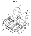
- Fig. 2 in conjunction with Figs. 1 and 3 shows a vehicle floor structure of a vehicle, of which only the center section in the region of two seat cross members 9, 9 is shown.
- the vehicle floor structure comprises two longitudinal members 7, 7, a center tunnel 3 in a floor panel 1 and two side sill assemblies 5, 5. Only a portion of a right one of the two side sill assemblies 5, 5 is shown in Fig. 2 . A portion of a left one of the two side sill assemblies 5, 5 is shown in Fig. 1 .
- the center tunnel 3 protrudes toward a passenger compartment 2 and runs or extends along the vehicle longitudinal center axis L-L (see Fig. 2 ).
- the center tunnel 3 holds the cross members 9, 9 so that they function as a single cross member between the two side sill assemblies 5, 5.
- a right longitudinal member 7 Disposed on the floor panel 1 between the right side sill assembly 5 and the center tunnel 3 is a right longitudinal member 7 that extends generally along the vehicle longitudinal center axis L-L.
- a left longitudinal member 7 Disposed on the floor panel 1 between the left side sill assembly 5 and the center tunnel 3 is a left longitudinal member 7 that extends generally along the vehicle longitudinal center axis L-L.
- the longitudinal members 7, 7 are rear extensions of two front side members, not shown, that extend rearwards from the front of the vehicle.
- the longitudinal members 7, 7 may be called front side member rear extensions.
- Each of the longitudinal members 7, 7 has a top wall 7a, two bent down side walls 7b, 7c from side edges of the top wall 7a, and downwardly facing laterally bent flanges 7d, 7e from bottom edges of the side walls 7b, 7c.
- the flanges 7d, 7e are fixedly connected to the floor panel 1.
- each of the longitudinal members 7, 7 has downwardly facing bent down legs 7b, 7d, and 7c, 7e connected to the floor panel 1.
- the two cross members 9, 9 of right and left are connected to the floor panel 1 on the right and left sides of the center tunnel 3. Stepping over the respective longitudinal members 7, 7, the cross members 9, 9 extend in the vehicle width direction. In other words, crossing the respective longitudinal members 7, 7, the cross members 9, 9 extend in the vehicle width direction.
- the cross member 9 passes, on a predetermined portion between outer and inner ends thereof, the longitudinal member 7. To avoid interference contact with the longitudinal member 7, the predetermined portion of the cross member 9 is cut upwardly from below to form a tunnel opening 9a that allows the passage of the longitudinal member 7.
- the cross member 9 has two flanges 9b extending along the vehicle longitudinal center axis L-L in the opposite directions from above the tunnel opening 9a. In Fig. 3 , only a front one 9b of the flanges is shown, but a rear one of the flanges is not shown. The front and rear flanges 9b are fixedly connected to a top wall 7a of the longitudinal member 7.
- Each of the cross members 9, 9 has a top wall 9c, two bent down side walls 9d, 9e from side edges of the top wall 9c, and downwardly facing bent flanges 9f, 9g (see Fig. 8 ) from bottom edges of the side walls 9d, 9e.
- the flanges 9f, 9g are fixedly connected to the floor panel 1.
- each of the cross members 9, 9 has downwardly facing bent down legs 9d, 9f, and 9e, 9g connected to the floor panel 1.
- each of the cross members 9, 9 has a flange 9h fixedly connected to a sill inner 5a of one of the side sill assemblies 5.
- each of the cross members 9, 9 has a flange 9i (see Fig. 2 ) fixedly connected to one of side walls 3a of the center tunnel 3.
- the side walls 3a slope downwards.
- the top wall 9c of each of cross member 9 is recessed at a predetermined area between the center tunnel 3 and the side sill assembly 5 to provide a recessed section 9j.
- the recessed section 9j of the top wall 9c is a flat top wall section 9j3.
- the flat top wall section 9j3 is lower in height than the two remaining sections of the top wall 9c which are not recessed.
- An inner one of the two remaining sections of the top wall 9c which are not recessed extends inwards from the inner end of the cross member 9 and connects into the recessed section 9j of the top wall 9c by way of an inner connecting portion 9j1, and an outer one thereof extends inwards from the outer end of the cross member 9 and connects into the recessed section 9j of the top wall 9c by way of an outer connecting portion 9j2.
- the inner connecting portion 9j1 includes a ramp between the top wall of the inner section of the top wall 9c which is not recessed and the flat top wall section 9j3 of the recessed section 9j. This ramp slopes downwards toward the flat top wall section 9j3 in a direction from the center tunnel 3 toward the side sill assembly 5.
- the outer connecting portion 9j2 includes a ramp between the top wall of the outer section of the top wall 9c which is not recessed and the flat top wall section 9j3 of the recessed section 9j. This ramp slopes downwards toward the flat top wall section 9j3 in a direction from the side sill assembly 5 toward the center tunnel 3.
- the inner connecting portion 9j1 is located between the longitudinal member 7 and the center tunnel 3, and the outer connecting portion is located between the longitudinal member 7 and the side sill assembly 5.
- the cross member 9 includes, between the longitudinal member 7 and the side sill assembly 5, the outer connecting portion 9j2 that divides the cross member 9 into two cross member portions (see Fig. 3 ).
- the two cross member portions include the remote cross member portion 32 from the outer end of the cross member 9 connected to the side sill assembly 5.
- This cross member portion 32 carries the top flat wall 9j3 of the recessed section 9j.
- the two cross member portions include the other cross member portion 34 adjacent to the side sill assembly 5.
- This cross member portion 34 carries the top wall 9c of the outer one of those remaining sections which are not recessed.
- the outer connecting portion 9j2 connects the remote cross member portion 32 and the other cross member portion 34 together.
- each cross member 9 with the above-mentioned recessed section 9j provides increased space under the associated one of seats 17 (see Fig. 2 ).
- the flat top wall section 9j3 of the remote cross member portion 32 is lower in height than the top wall of the other cross member portion 34. Because the ramp 36 slopes downwards toward the flat top wall section 9j3 in the direction from the side sill assembly 5 toward the center tunnel 3, the connecting portion 9j2 provides a transition in cross sectional profile between the different cross sectional profiles of the two cross member portions 32 and 34.
- each cross member 9 is another cross member 13.
- the associated seat 17 is installed via a seat slide mechanism 15 on the sections of the top wall 9c which are not recessed of the cross member and a top wall of the cross member 13.
- each cross member 9 is reinforced by an internal reinforcement element 19.
- the reinforcement element 19, within each cross member 9, extends through the connecting portion 9j2 into the remote cross member portion 32 and terminating in at its inner end 19b spaced by a gap 23 from a top wall 7a of the longitudinal member 7.
- the reinforcement element 19 is connected, on its top wall 19c, to an upper inner wall 9m of the remote cross member portion 32 to reinforce same.
- the reinforcement element 19 extends into the other cross member portion 34 and terminating in at its outer end 19a in the neighborhood of the side sill assembly 5 (see Fig. 1 ).
- the reinforcement element 19 is spaced from an upper inner wall 9n of the other cross member portion 34 to provide a gap 21.
- a center pillar (or a B-pillar) 20 extends upwardly from the side sill assembly 5.
- the center pillar 20 includes a pillar inner 20a and a pillar outer 20b. At its lower end portion, the pillar inner 20a is fixedly connected to a sill outer 5b of the side sill assembly 5.
- the cross member 9 and the center pillar 20 lie in the common transverse plane with respect to the longitudinal center axis L-L (see Fig. 2 ) of the vehicle.
- the reinforcement element 19 forms the gap 21 with the upper inner wall 9n of the other cross member portion 34 of the cross member 9 in approximately half of its entire length on the side of the outer end 19a, that is, the outer side of the connecting portion 9j2.
- the reinforcement element 19 has its outer end 19a disposed adjacent to the side sill assembly 5 and its top wall 19c spaced from the upper inner wall 9n of the cross member 9 on the side of its outer end 19a.
- the reinforcement element 19 forms a gap 23 (see Fig. 1 ) with the top wall 7a of the longitudinal member 7 on the side of the inner end 19b, that is, the inner side of the connecting portion 9j2. This means that the reinforcement element 19 has its inner end 19b spaced by a gap 23 from the top wall 7a of the longitudinal member 7.
- the reinforcement element 19 has a cross sectional profile of a vertically inversed U and includes bent down side walls 19d and 19e from the top wall 19c.
- the reinforcement element 19 has its top wall 19c fixedly connected to the upper inner wall 9m on the opposite side of the flat top wall section 9j3 on the inner side near the longitudinal member 7, that is, the inner side of the connecting portion 9j2. This means that the top wall 19c of the portion of the reinforcement element 19 on the side of the inner end 19b is fixedly connected to the upper inner wall 9m of the cross member 9 on the opposite side of the flat top wall 9j3.
- a lower side impact load in the direction F1 of the arrow is applied to the side sill assembly 5 adjacent to the bottom end of the center pillar 20 in the event of a side collision.
- the lower impact load F1 acts on the cross member 9 and the reinforcement element 19 in their longitudinal direction.
- the illustration of the center pillar 20 and the sill outer 5b is hereby omitted.
- the cross member 9 is reinforced by the reinforcement element 19 to maintain the required setting level of strength.
- the cross member 9 and the reinforcement element 19 are spaced from each other to form the gap 21 on that portion which is disposed on the side of the side sill assembly 5.
- the strength of that cross member portion 34 of the cross member 9 which is spaced from the reinforcement element 19 does not rise too much so that the cross member portion 34 is compressed and broken in the longitudinal direction efficiently to absorb the impact energy.
- cross member 9 is stable enough, but has the cross member portion 34 which is compressed and broken in a longitudinal direction when the cross member 9 is stressed in the longitudinal direction by the lower side impact load F1 to absorb the impact energy in the event of a side collision.
- an upper side impact load in the direction F2 of the arrow is applied to the center pillar 20 at a portion above the side sill assembly 5 in the event of a side collision.
- the cross member 9 and the reinforcement element 19 are deformed and bent on that zone 25 where the cross member 9 and the reinforcement element 19 are fixedly connected to each other so that the portions of the cross member 9 and the reinforcement element 19 on the side of the side sill assembly 5 move upwardly, thereby to absorb the impact energy.
- the cross member 9 and the reinforcement element 19 are bent and deformed on that portion where the reinforcement element 19 is fixedly connected to the cross member 9 in such a direction to allow an upward movement of the side sill assembly 5 until the inner end 19b of the reinforcement element 19 contacts with the top wall 7a of the longitudinal member 7 when the cross member 9 is stressed in a rotational direction by the upper impact load F2 applied to the center pillar 20 above the side sill assembly 5 in the event of a side collision. Because further deformation and bending of the cross member 9 and the reinforcement element 19 end after the inner end 19b of the reinforcement element 19 contacts with the top wall 7a of the longitudinal member 7, a shape-locking connection is created to secure a space within the passenger compartment 2 in the event of a side collision.
- the cross member 9 is located under the passenger compartment 2 as high as the longitudinal member 7, which is a rear extension of a front side member, and the cross member 9 and the center pillar 20 lie in the common transverse plane with respect the vehicle longitudinal center axis L-L.
- the cross member 9 and the center pillar 20 lie in the common transverse plane with respect the vehicle longitudinal center axis L-L.
- the reinforcement element 19 is stiff enough to bear the load to restrain the deformation of the cross member 9. This suppresses the movement of the seat 17 along the vehicle longitudinal axis L-L (see Fig. 3 ) in the event of a front end collision.
Abstract
Description
- The present application claims the priority of Japanese Patent Application No.
2007-178399, filed July 6, 2007 - The present invention relates to a vehicle floor structure for a motor vehicle.
-
JP-A 8-80874 JP Pat. No. 3381404 - An object of the present invention is to provide a vehicle floor structure with a seat cross member in a floor which is stable but which guarantees optimal deforming and/or bending properties to absorb the impact load in the event of a side collision.
- According to one aspect of the present invention, there is provided a vehicle floor structure for a motor vehicle, comprising:
- a side sill assembly on each side of the vehicle;
- a longitudinal member;
- a cross member passing, on a predetermined portion between outer and inner ends thereof, the longitudinal member and providing a gap above the longitudinal member,
- the cross member being connected, on an outer end thereof, to the side sill assembly,
- the cross member including, between the longitudinal member and the side sill assembly, a connecting portion that divides the cross member into two cross member portions and connects the two cross member portions together, the two cross member portions including a remote cross member portion from the outer end of the cross member and the other cross member portion; and
- a reinforcement element extending through the connecting portion into the remote cross member portion and terminating in at an inner end thereof spaced above from a top wall of the longitudinal member, the reinforcement element being connected to an upper inner wall of the remote cross member portion to reinforce same, the reinforcement element extending into the other cross member portion and terminating in at an outer end thereof in the neighborhood of the side sill assembly, the reinforcement element being spaced from an upper inner wall of the other cross member portion.
-
-
Fig. 1 is a fragmentary section taken through the line I-I inFig. 2 with a side sill assembly and a lateral load beam on the left side of a passenger car; -
Fig. 2 is a fragmentary perspective view of a vehicle floor structure according to the present invention with two lateral load beams and a side sill assembly on the left side removed; -
Fig. 3 is a magnified view of a portion enclosed by a circle III inFig. 2 with an inner sill of the side sill assembly on the left side of the passenger car; -
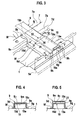
Fig. 4 is a fragmentary section taken through the line IV-IV inFig. 3 ; -
Fig. 5 is a fragmentary section taken through the line V-V inFig. 3 ; -
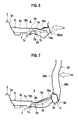
Fig. 6 schematically illustrates the state that the cross member is stable enough, but has a predefined portion which is compressed and broken in a longitudinal direction when the cross member is stressed in the longitudinal direction by a side impact load in the event of a side collision. -
Fig. 7 schematically illustrates the state that a shape-locking connection is created to secure a space within a passenger compartment in the event of a side collision. -
Fig. 8 schematically illustrates the state that a reinforcement element bears load to restrain deformation of the cross member to suppress movement of the associated seat in the vehicle longitudinal center axis in the event of a front end collision. - Initially it is noted that the drawings referred to hereinafter as illustrating the preferred embodiment of the present invention are not to scale and are schematic in nature and, therefore, should not be taken too literally. Nevertheless, the drawings illustrate the invention sufficiently to enable one skilled in the art to practice the invention.
-
Fig. 2 in conjunction withFigs. 1 and3 shows a vehicle floor structure of a vehicle, of which only the center section in the region of twoseat cross members longitudinal members center tunnel 3 in afloor panel 1 and twoside sill assemblies side sill assemblies Fig. 2 . A portion of a left one of the twoside sill assemblies Fig. 1 . Thecenter tunnel 3 protrudes toward apassenger compartment 2 and runs or extends along the vehicle longitudinal center axis L-L (seeFig. 2 ). Thecenter tunnel 3 holds thecross members side sill assemblies - Disposed on the
floor panel 1 between the rightside sill assembly 5 and thecenter tunnel 3 is a rightlongitudinal member 7 that extends generally along the vehicle longitudinal center axis L-L. Disposed on thefloor panel 1 between the leftside sill assembly 5 and thecenter tunnel 3 is a leftlongitudinal member 7 that extends generally along the vehicle longitudinal center axis L-L. In the embodiment, thelongitudinal members longitudinal members - Each of the
longitudinal members top wall 7a, two bent downside walls top wall 7a, and downwardly facing laterallybent flanges side walls flanges floor panel 1. In other words, each of thelongitudinal members legs floor panel 1. - Interposing the
center tunnel 3, the twocross members floor panel 1 on the right and left sides of thecenter tunnel 3. Stepping over the respectivelongitudinal members cross members longitudinal members cross members - As best seen in
Fig. 3 , thecross member 9 passes, on a predetermined portion between outer and inner ends thereof, thelongitudinal member 7. To avoid interference contact with thelongitudinal member 7, the predetermined portion of thecross member 9 is cut upwardly from below to form atunnel opening 9a that allows the passage of thelongitudinal member 7. Thecross member 9 has twoflanges 9b extending along the vehicle longitudinal center axis L-L in the opposite directions from above the tunnel opening 9a. InFig. 3 , only a front one 9b of the flanges is shown, but a rear one of the flanges is not shown. The front andrear flanges 9b are fixedly connected to atop wall 7a of thelongitudinal member 7. - Each of the
cross members top wall 9c, two bent downside walls top wall 9c, and downwardly facingbent flanges Fig. 8 ) from bottom edges of theside walls flanges floor panel 1. In other words, each of thecross members legs floor panel 1. - As shown in
Fig. 1 , at its outer end, each of thecross members flange 9h fixedly connected to a sill inner 5a of one of theside sill assemblies 5. At its inner end, each of thecross members flange 9i (seeFig. 2 ) fixedly connected to one ofside walls 3a of thecenter tunnel 3. Theside walls 3a slope downwards. - The
top wall 9c of each ofcross member 9 is recessed at a predetermined area between thecenter tunnel 3 and theside sill assembly 5 to provide arecessed section 9j. Therecessed section 9j of thetop wall 9c is a flat top wall section 9j3. The flat top wall section 9j3 is lower in height than the two remaining sections of thetop wall 9c which are not recessed. An inner one of the two remaining sections of thetop wall 9c which are not recessed extends inwards from the inner end of thecross member 9 and connects into therecessed section 9j of thetop wall 9c by way of an inner connecting portion 9j1, and an outer one thereof extends inwards from the outer end of thecross member 9 and connects into therecessed section 9j of thetop wall 9c by way of an outer connecting portion 9j2. The inner connecting portion 9j1 includes a ramp between the top wall of the inner section of thetop wall 9c which is not recessed and the flat top wall section 9j3 of therecessed section 9j. This ramp slopes downwards toward the flat top wall section 9j3 in a direction from thecenter tunnel 3 toward theside sill assembly 5. The outer connecting portion 9j2 includes a ramp between the top wall of the outer section of thetop wall 9c which is not recessed and the flat top wall section 9j3 of therecessed section 9j. This ramp slopes downwards toward the flat top wall section 9j3 in a direction from theside sill assembly 5 toward thecenter tunnel 3. The inner connecting portion 9j1 is located between thelongitudinal member 7 and thecenter tunnel 3, and the outer connecting portion is located between thelongitudinal member 7 and theside sill assembly 5. - From the above description, it is noted that the
cross member 9 includes, between thelongitudinal member 7 and theside sill assembly 5, the outer connecting portion 9j2 that divides thecross member 9 into two cross member portions (seeFig. 3 ). The two cross member portions include the remotecross member portion 32 from the outer end of thecross member 9 connected to theside sill assembly 5. Thiscross member portion 32 carries the top flat wall 9j3 of the recessedsection 9j. The two cross member portions include the othercross member portion 34 adjacent to theside sill assembly 5. Thiscross member portion 34 carries thetop wall 9c of the outer one of those remaining sections which are not recessed. The outer connecting portion 9j2 connects the remotecross member portion 32 and the othercross member portion 34 together. - Forming each
cross member 9 with the above-mentioned recessedsection 9j provides increased space under the associated one of seats 17 (seeFig. 2 ). Referring also toFig. 3 , the flat top wall section 9j3 of the remotecross member portion 32 is lower in height than the top wall of the othercross member portion 34. Because theramp 36 slopes downwards toward the flat top wall section 9j3 in the direction from theside sill assembly 5 toward thecenter tunnel 3, the connecting portion 9j2 provides a transition in cross sectional profile between the different cross sectional profiles of the twocross member portions - Referring to
Fig. 2 , arranged behind, with respect to the vehicle longitudinal axis L-L, eachcross member 9 is anothercross member 13. The associatedseat 17 is installed via aseat slide mechanism 15 on the sections of thetop wall 9c which are not recessed of the cross member and a top wall of thecross member 13. - Referring to
Figs. 1 ,3, 4 and 5 , eachcross member 9 is reinforced by aninternal reinforcement element 19. Thereinforcement element 19, within eachcross member 9, extends through the connecting portion 9j2 into the remotecross member portion 32 and terminating in at itsinner end 19b spaced by agap 23 from atop wall 7a of thelongitudinal member 7. As best seen inFig. 4 , thereinforcement element 19 is connected, on itstop wall 19c, to an upperinner wall 9m of the remotecross member portion 32 to reinforce same. Thereinforcement element 19 extends into the othercross member portion 34 and terminating in at itsouter end 19a in the neighborhood of the side sill assembly 5 (seeFig. 1 ). As best seen inFig. 5 , thereinforcement element 19 is spaced from an upperinner wall 9n of the othercross member portion 34 to provide agap 21. - Turning back to
Fig. 1 , at that portion of theside sill assembly 5 which is connected by thecross member 9, a center pillar (or a B-pillar) 20 extends upwardly from theside sill assembly 5. Thecenter pillar 20 includes a pillar inner 20a and a pillar outer 20b. At its lower end portion, the pillar inner 20a is fixedly connected to a sill outer 5b of theside sill assembly 5. Thecross member 9 and thecenter pillar 20 lie in the common transverse plane with respect to the longitudinal center axis L-L (seeFig. 2 ) of the vehicle. - The
reinforcement element 19 forms thegap 21 with the upperinner wall 9n of the othercross member portion 34 of thecross member 9 in approximately half of its entire length on the side of theouter end 19a, that is, the outer side of the connecting portion 9j2. Thus, thereinforcement element 19 has itsouter end 19a disposed adjacent to theside sill assembly 5 and itstop wall 19c spaced from the upperinner wall 9n of thecross member 9 on the side of itsouter end 19a. - The
reinforcement element 19 forms a gap 23 (seeFig. 1 ) with thetop wall 7a of thelongitudinal member 7 on the side of theinner end 19b, that is, the inner side of the connecting portion 9j2. This means that thereinforcement element 19 has itsinner end 19b spaced by agap 23 from thetop wall 7a of thelongitudinal member 7. - As is seen from
Figs. 4 and 5 , thereinforcement element 19 has a cross sectional profile of a vertically inversed U and includes bent downside walls top wall 19c. - Thus, the
reinforcement element 19 has itstop wall 19c fixedly connected to the upperinner wall 9m on the opposite side of the flat top wall section 9j3 on the inner side near thelongitudinal member 7, that is, the inner side of the connecting portion 9j2. This means that thetop wall 19c of the portion of thereinforcement element 19 on the side of theinner end 19b is fixedly connected to the upperinner wall 9m of thecross member 9 on the opposite side of the flat top wall 9j3. - As shown in
Fig. 6 , a lower side impact load in the direction F1 of the arrow is applied to theside sill assembly 5 adjacent to the bottom end of thecenter pillar 20 in the event of a side collision. Smashing the bottom end of thecenter pillar 20 and theside sill assembly 5, the lower impact load F1 acts on thecross member 9 and thereinforcement element 19 in their longitudinal direction. InFig. 6 , the illustration of thecenter pillar 20 and the sill outer 5b is hereby omitted. - The
cross member 9 is reinforced by thereinforcement element 19 to maintain the required setting level of strength. Thecross member 9 and thereinforcement element 19 are spaced from each other to form thegap 21 on that portion which is disposed on the side of theside sill assembly 5. Thus, the strength of thatcross member portion 34 of thecross member 9 which is spaced from thereinforcement element 19 does not rise too much so that thecross member portion 34 is compressed and broken in the longitudinal direction efficiently to absorb the impact energy. - It is noted that the
cross member 9 is stable enough, but has thecross member portion 34 which is compressed and broken in a longitudinal direction when thecross member 9 is stressed in the longitudinal direction by the lower side impact load F1 to absorb the impact energy in the event of a side collision. - As shown in
Fig. 7 , an upper side impact load in the direction F2 of the arrow is applied to thecenter pillar 20 at a portion above theside sill assembly 5 in the event of a side collision. Thecross member 9 and thereinforcement element 19 are deformed and bent on thatzone 25 where thecross member 9 and thereinforcement element 19 are fixedly connected to each other so that the portions of thecross member 9 and thereinforcement element 19 on the side of theside sill assembly 5 move upwardly, thereby to absorb the impact energy. - The above-mentioned deformation and bending continue until the
gap 23 disappears, that is, thereinforcement element 19 contacts with thetop wall 7a of thelongitudinal member 7. After the deformation and bending, theinner end 19b or its adjacent portion contacts with thetop wall 7a to suppress further deformation and bending, thus securing a space within thepassenger compartment 3 in the event of a side collision. - It is noted that the
cross member 9 and thereinforcement element 19 are bent and deformed on that portion where thereinforcement element 19 is fixedly connected to thecross member 9 in such a direction to allow an upward movement of theside sill assembly 5 until theinner end 19b of thereinforcement element 19 contacts with thetop wall 7a of thelongitudinal member 7 when thecross member 9 is stressed in a rotational direction by the upper impact load F2 applied to thecenter pillar 20 above theside sill assembly 5 in the event of a side collision. Because further deformation and bending of thecross member 9 and thereinforcement element 19 end after theinner end 19b of thereinforcement element 19 contacts with thetop wall 7a of thelongitudinal member 7, a shape-locking connection is created to secure a space within thepassenger compartment 2 in the event of a side collision. - In the embodiment, the
cross member 9 is located under thepassenger compartment 2 as high as thelongitudinal member 7, which is a rear extension of a front side member, and thecross member 9 and thecenter pillar 20 lie in the common transverse plane with respect the vehicle longitudinal center axis L-L. Thus, a space within thepassenger compartment 2 is secured in the event of a side collision where the upper impact load F2 is applied to thecenter pillar 20. - As shown in
Fig. 8 , in the event of a front end collision; an impact load F3 is applied. In this case, thereinforcement element 19 is stiff enough to bear the load to restrain the deformation of thecross member 9. This suppresses the movement of theseat 17 along the vehicle longitudinal axis L-L (seeFig. 3 ) in the event of a front end collision. - While the preferred embodiment of the present invention has been described with particularly herein, it is considered apparent that the present invention is capable of numerous modifications, replacements, and substitutions of parts and, therefore, is not to be limited. Rather, the present invention is only to be defined by the claims appended hereto, including equivalents thereof.
Claims (9)
- A vehicle floor structure for a motor vehicle, comprising:a side sill assembly (5) on each side of the vehicle;a longitudinal member (7);a cross member (9) passing, on a predetermined portion between outer and inner ends thereof, the longitudinal member (7) and providing a gap (30) above the longitudinal member (7),the cross member (9) being connected, on an outer end thereof, to the side sill assembly (5),the cross member (9) including, between the longitudinal member (7) and the side sill assembly (5), a connecting portion (9j2) that divides the cross member (9) into two cross member portions (32, 34) and connects the two cross member portions (32, 34) together, the two cross member portions (32, 34) including a remote cross member portion (32) from the outer end of the cross member and the other cross member portion (34); anda reinforcement element (19) extending through the connecting portion (9j2) into the remote cross member portion (32) and terminating in at an inner end (19b) thereof spaced by a gap (23) from a top wall (7a) of the longitudinal member (7), the reinforcement element (19) being connected to an upper inner wall (9m) of the remote cross member portion (32) to reinforce same (32), the reinforcement element (19) extending into the other cross member portion (34) and terminating in at an outer end (19a) thereof in the neighborhood of the side sill assembly (5), the reinforcement element (19) being spaced from an upper inner wall (9n) of the other cross member portion (34).
- The vehicle floor structure as claimed in claim 1, wherein a top wall (9j3) of the remote cross member portion (32) is lower in height than a top wall (9c) of the other cross member portion (34), and the connecting portion (9j2) includes a ramp (36) between the top walls (9j3, 9c) of the two cross member portions (32, 34).
- The vehicle floor structure as claimed in claim 1 or 2, wherein the longitudinal member (7) and the cross member (9) are disposed under a passenger compartment (2) of the vehicle.
- The vehicle floor structure as claimed in claim 3, wherein the cross member (9) and a center pillar (20) lie in the common transverse plane with respect to a longitudinal center axis (L-L) of the vehicle.
- The vehicle floor structure as claimed in claim 1, wherein the cross member (9) is a seat cross member.
- The vehicle floor structure as claimed in claim 1, wherein the cross member (9) is connected, on the inner end, to a center tunnel (3) of the vehicle.
- The vehicle floor structure as claimed in any one of the preceding claims 1 to 6, wherein the cross member (9) is stable enough, but has a predefined portion which is compressed and broken in a longitudinal direction when the cross member (9) is stressed in the longitudinal direction by a lower side impact load (F1) which is applied to the side sill assembly in the event of a side collision.
- The vehicle floor structure as claimed in any one of the preceding claims 1 to 7, wherein the cross member (9) and the reinforcement element (19) are bent and deformed on that portion where the reinforcement element (19) is fixedly connected to the cross member (9) in such a direction to allow an upward movement of the side sill assembly (5) until the inner end (19b) of the reinforcement element (19) contacts with the top wall (7a) of the longitudinal member (7) when the cross member (9) is stressed in a rotational direction by an upper side impact load (F2) which is applied to above the side sill assembly in the event of a side collision, thereby creating a self-locking connection to secure a space within a passenger compartment (2) of the vehicle.
- The vehicle floor structure as claimed in any one of the preceding claims 1 to 7, wherein the cross member (9) and the reinforcement element (19) are bent and deformed on that portion where the reinforcement element (19) is fixedly connected to the cross member (9) in such a direction to allow an upward movement of the side sill assembly (5) until the inner end (19b) of the reinforcement element (19) contacts with the top wall (7a) of the longitudinal member (7) when the cross member (9) is stressed in a rotational direction, thereby creating a self-locking connection to secure a space within a passenger compartment (2) of the vehicle.
Applications Claiming Priority (1)
| Application Number | Priority Date | Filing Date | Title |
|---|---|---|---|
| JP2007178399A JP4900095B2 (en) | 2007-07-06 | 2007-07-06 | Auto body floor structure |
Publications (3)
| Publication Number | Publication Date |
|---|---|
| EP2011719A2 true EP2011719A2 (en) | 2009-01-07 |
| EP2011719A3 EP2011719A3 (en) | 2009-06-24 |
| EP2011719B1 EP2011719B1 (en) | 2010-06-23 |
Family
ID=39683917
Family Applications (1)
| Application Number | Title | Priority Date | Filing Date |
|---|---|---|---|
| EP08011591A Active EP2011719B1 (en) | 2007-07-06 | 2008-06-26 | Vehicle floor structure for a motor vehicle |
Country Status (5)
| Country | Link |
|---|---|
| US (1) | US7644978B2 (en) |
| EP (1) | EP2011719B1 (en) |
| JP (1) | JP4900095B2 (en) |
| CN (1) | CN101337561B (en) |
| DE (1) | DE602008001580D1 (en) |
Cited By (5)
| Publication number | Priority date | Publication date | Assignee | Title |
|---|---|---|---|---|
| EP2487090A3 (en) * | 2011-02-11 | 2013-08-28 | Audi AG | Cross-member of a motor vehicle and motor vehicle with such a cross-member |
| EP2823928A4 (en) * | 2012-03-06 | 2015-07-08 | Jfe Steel Corp | Coupling structure |
| WO2016188802A1 (en) * | 2015-05-22 | 2016-12-01 | Bayerische Motoren Werke Aktiengesellschaft | Transverse carrier for a motor vehicle |
| EP3578444A4 (en) * | 2017-03-10 | 2020-03-04 | Mazda Motor Corporation | Lower vehicle body structure for vehicle |
| FR3132072A1 (en) * | 2022-01-26 | 2023-07-28 | Psa Automobiles Sa | DEFORMABLE STRUCTURAL PART IN THE EVENT OF A SIDE IMPACT, FOR A VEHICLE |
Families Citing this family (38)
| Publication number | Priority date | Publication date | Assignee | Title |
|---|---|---|---|---|
| JP4407713B2 (en) * | 2007-03-30 | 2010-02-03 | 日産自動車株式会社 | Body structure |
| US7854472B2 (en) * | 2007-10-22 | 2010-12-21 | Honda Motor Co., Ltd. | Vehicle body structure |
| US7828370B2 (en) * | 2007-10-25 | 2010-11-09 | Honda Motor Co., Ltd. | Vehicle body structure |
| DE102008009804A1 (en) * | 2008-02-19 | 2009-08-20 | Dr. Ing. H.C. F. Porsche Aktiengesellschaft | Bodenmittelteil a vehicle body |
| JP4690450B2 (en) * | 2008-12-19 | 2011-06-01 | 本田技研工業株式会社 | Body floor structure |
| DE102009042187A1 (en) * | 2009-09-18 | 2011-03-24 | Audi Ag | Vehicle body structure in the floor area of the occupant cabin and associated production process |
| WO2011055936A2 (en) * | 2009-11-03 | 2011-05-12 | (주)브이이엔에스 | Motor vehicle |
| US8235459B2 (en) | 2010-04-07 | 2012-08-07 | Honda Motor Co., Ltd.. | Seat support assembly |
| CN101837754A (en) * | 2010-05-25 | 2010-09-22 | 三一重机有限公司 | Mining dump truck carriage floor reinforcing rib structure |
| FR2962967B1 (en) * | 2010-07-23 | 2013-02-22 | Renault Sa | AUTOMOTIVE CHASSIS WITH SIDE SUPPORT LATERAL REINFORCEMENT |
| JP5585530B2 (en) * | 2010-08-25 | 2014-09-10 | マツダ株式会社 | Lower body structure of the vehicle |
| JP5558588B2 (en) * | 2010-12-24 | 2014-07-23 | 本田技研工業株式会社 | Auto body structure |
| EP2647554B1 (en) * | 2011-09-01 | 2014-10-22 | Toyota Jidosha Kabushiki Kaisha | Car body structure |
| JP5776528B2 (en) * | 2011-12-07 | 2015-09-09 | トヨタ自動車株式会社 | Body floor structure |
| JP5582262B2 (en) * | 2011-12-07 | 2014-09-03 | トヨタ自動車株式会社 | Lower body structure |
| US9290209B2 (en) * | 2012-03-29 | 2016-03-22 | Toyota Jidosha Kabushiki Kaisha | Vehicle body lower structure |
| JP6007643B2 (en) * | 2012-07-30 | 2016-10-12 | マツダ株式会社 | Upper body structure of the vehicle |
| JP5728523B2 (en) * | 2013-04-17 | 2015-06-03 | 本田技研工業株式会社 | Body structure |
| KR101526397B1 (en) * | 2013-12-18 | 2015-06-05 | 현대자동차 주식회사 | Structure for reinforcing seat mounting portion of vehicle body |
| US9114730B1 (en) * | 2014-02-19 | 2015-08-25 | International Truck Intellectual Property Company, Llc | Seat mounting structure in vehicle floor frame |
| FR3024421B1 (en) * | 2014-08-04 | 2016-07-15 | Peugeot Citroen Automobiles Sa | CROSS FLOOR COMPRISING A REPORTED PORTION DEFORMABLE IN COMPRESSION |
| US9302715B2 (en) | 2014-09-10 | 2016-04-05 | Toyota Motor Engineering & Manufacturing North America, Inc. | Vehicles having side support reinforcement gussets |
| US9487243B2 (en) | 2014-12-09 | 2016-11-08 | Ford Global Technologies, Llc | Vehicle body structure |
| KR101714169B1 (en) | 2015-07-15 | 2017-03-08 | 현대자동차주식회사 | Floor body for vehicle |
| JP6319215B2 (en) * | 2015-07-17 | 2018-05-09 | トヨタ自動車株式会社 | Vehicle skeleton structure |
| JP6398906B2 (en) * | 2015-08-17 | 2018-10-03 | トヨタ自動車株式会社 | Vehicle side structure |
| JP6236428B2 (en) * | 2015-10-22 | 2017-11-22 | 本田技研工業株式会社 | Body side structure |
| WO2017098302A1 (en) * | 2015-12-09 | 2017-06-15 | Arcelormittal | Vehicle underbody structure comprising a reinforcement element between a longitudinal beam and a lowerside sill part |
| CN109789898B (en) * | 2016-09-21 | 2021-10-12 | 本田技研工业株式会社 | Seat mounting structure |
| JP6631474B2 (en) * | 2016-11-08 | 2020-01-15 | トヨタ自動車株式会社 | Vehicle rear structure |
| JP6919187B2 (en) * | 2016-12-15 | 2021-08-18 | 三菱自動車工業株式会社 | Body floor structure |
| JP6650920B2 (en) * | 2017-12-14 | 2020-02-19 | 本田技研工業株式会社 | Body floor structure |
| KR102440612B1 (en) * | 2017-12-15 | 2022-09-05 | 현대자동차 주식회사 | Side vehicle body reinforcing structure |
| JP6915592B2 (en) * | 2018-06-15 | 2021-08-04 | マツダ株式会社 | Lower body structure |
| FR3082496B1 (en) * | 2018-06-19 | 2020-08-21 | Psa Automobiles Sa | AUTOMOTIVE VEHICLE CHASSIS, PROVIDED WITH A PART TAKING ANTAGONISTIC SUPPORT AGAINST A CROSSMOUNT AND A SIDING IN THE EVENT OF SIDE IMPACT. |
| EP3828027A1 (en) * | 2019-11-27 | 2021-06-02 | MAGNA STEYR Fahrzeugtechnik AG & Co KG | Seat module for a motor vehicle |
| JP2021094941A (en) * | 2019-12-13 | 2021-06-24 | 本田技研工業株式会社 | Floor structure |
| JP2023153598A (en) * | 2022-04-05 | 2023-10-18 | マツダ株式会社 | Lower vehicle-body structure of vehicle |
Citations (2)
| Publication number | Priority date | Publication date | Assignee | Title |
|---|---|---|---|---|
| JPH0880874A (en) | 1994-09-14 | 1996-03-26 | Nissan Motor Co Ltd | Car body floor structure for automobile |
| JP2007178399A (en) | 2005-12-28 | 2007-07-12 | Citizen Miyota Co Ltd | Pendulum type sensor |
Family Cites Families (18)
| Publication number | Priority date | Publication date | Assignee | Title |
|---|---|---|---|---|
| US4514008A (en) * | 1981-06-05 | 1985-04-30 | Toyota Jidosha Kogyo Kabushiki Kaisha | Vehicle body floor construction of motor vehicle |
| JPH0450582A (en) * | 1990-06-15 | 1992-02-19 | Tokin Corp | Switch valve |
| JPH06171551A (en) * | 1992-12-11 | 1994-06-21 | Mazda Motor Corp | Automotive lower car body structure |
| JP3435910B2 (en) * | 1995-07-13 | 2003-08-11 | 日産自動車株式会社 | Car body structure |
| US6227610B1 (en) | 1998-02-19 | 2001-05-08 | Honda Giken Kogyo Kabushiki Kaisha | Cross member of an automobile body |
| DE19954296C2 (en) * | 1999-11-11 | 2003-06-18 | Porsche Ag | vehicle |
| JP2001233254A (en) * | 2000-02-22 | 2001-08-28 | Mitsubishi Automob Eng Co Ltd | Vehicle body structure |
| EP1186453B1 (en) * | 2000-08-19 | 2003-01-08 | Benteler Ag | Side intrusion beam |
| KR100405892B1 (en) * | 2001-04-19 | 2003-11-14 | 기아자동차주식회사 | Floor panel assembly having improved stiffness against side impact |
| US6666501B1 (en) * | 2002-07-17 | 2003-12-23 | Daimlerchrysler Corporation | Lightweight automobile body structure |
| DE10232840A1 (en) | 2002-07-19 | 2004-02-05 | Volkswagen Ag | Floor structure on motor vehicles |
| JP3962003B2 (en) * | 2003-10-16 | 2007-08-22 | 本田技研工業株式会社 | Body structure |
| DE602005015218D1 (en) * | 2005-09-08 | 2009-08-13 | Ford Global Tech Llc | Impact protection structure |
| JP4400548B2 (en) * | 2005-11-02 | 2010-01-20 | トヨタ自動車株式会社 | Lower body structure |
| JP4747812B2 (en) * | 2005-12-01 | 2011-08-17 | マツダ株式会社 | Lower body structure of the vehicle |
| EP2006191B1 (en) * | 2007-06-19 | 2010-04-21 | Honda Motor Co., Ltd. | Vehicle body floor structure |
| US7854472B2 (en) * | 2007-10-22 | 2010-12-21 | Honda Motor Co., Ltd. | Vehicle body structure |
| US20090174220A1 (en) * | 2008-01-07 | 2009-07-09 | Gm Global Technology Operations, Inc. | Vehicle Body Structure with Linking Bracket for a Vehicle Side Pillar |
-
2007
- 2007-07-06 JP JP2007178399A patent/JP4900095B2/en active Active
-
2008
- 2008-06-25 US US12/145,955 patent/US7644978B2/en active Active
- 2008-06-26 DE DE602008001580T patent/DE602008001580D1/en active Active
- 2008-06-26 EP EP08011591A patent/EP2011719B1/en active Active
- 2008-07-03 CN CN2008101318764A patent/CN101337561B/en active Active
Patent Citations (3)
| Publication number | Priority date | Publication date | Assignee | Title |
|---|---|---|---|---|
| JPH0880874A (en) | 1994-09-14 | 1996-03-26 | Nissan Motor Co Ltd | Car body floor structure for automobile |
| JP3381404B2 (en) | 1994-09-14 | 2003-02-24 | 日産自動車株式会社 | Car body floor structure |
| JP2007178399A (en) | 2005-12-28 | 2007-07-12 | Citizen Miyota Co Ltd | Pendulum type sensor |
Cited By (7)
| Publication number | Priority date | Publication date | Assignee | Title |
|---|---|---|---|---|
| EP2487090A3 (en) * | 2011-02-11 | 2013-08-28 | Audi AG | Cross-member of a motor vehicle and motor vehicle with such a cross-member |
| EP2823928A4 (en) * | 2012-03-06 | 2015-07-08 | Jfe Steel Corp | Coupling structure |
| WO2016188802A1 (en) * | 2015-05-22 | 2016-12-01 | Bayerische Motoren Werke Aktiengesellschaft | Transverse carrier for a motor vehicle |
| EP3578444A4 (en) * | 2017-03-10 | 2020-03-04 | Mazda Motor Corporation | Lower vehicle body structure for vehicle |
| US11077881B2 (en) | 2017-03-10 | 2021-08-03 | Mazda Motor Corporation | Lower vehicle body structure for vehicle |
| FR3132072A1 (en) * | 2022-01-26 | 2023-07-28 | Psa Automobiles Sa | DEFORMABLE STRUCTURAL PART IN THE EVENT OF A SIDE IMPACT, FOR A VEHICLE |
| WO2023144466A1 (en) * | 2022-01-26 | 2023-08-03 | Psa Automobiles Sa | Structural part that is deformable in the event of a side impact, for a vehicle |
Also Published As
| Publication number | Publication date |
|---|---|
| DE602008001580D1 (en) | 2010-08-05 |
| EP2011719B1 (en) | 2010-06-23 |
| US20090066118A1 (en) | 2009-03-12 |
| JP4900095B2 (en) | 2012-03-21 |
| CN101337561A (en) | 2009-01-07 |
| CN101337561B (en) | 2010-09-08 |
| EP2011719A3 (en) | 2009-06-24 |
| JP2009012674A (en) | 2009-01-22 |
| US7644978B2 (en) | 2010-01-12 |
Similar Documents
| Publication | Publication Date | Title |
|---|---|---|
| EP2011719B1 (en) | Vehicle floor structure for a motor vehicle | |
| JP5354154B2 (en) | Automobile frame structure | |
| EP1927533B1 (en) | Vehicle body side portion structure | |
| CN109204547B (en) | Vehicle body structure for vehicle | |
| CN107206877B (en) | Reinforced vehicle door resistant to side impact | |
| JP4840196B2 (en) | Vehicle skeleton structure | |
| JP4483843B2 (en) | Reinforcement structure of body frame | |
| CN110228534B (en) | Vehicle center pillar | |
| EP2783951A1 (en) | Vehicle body superstructure | |
| EP1812277B1 (en) | Arrangement for vehicle cabs | |
| US9809253B2 (en) | Vehicle body lower portion structure | |
| EP2708449B1 (en) | Vehicle structure | |
| CN111152850A (en) | Lower body structure of vehicle | |
| CN112109601B (en) | System comprising a vehicle seat track and a support | |
| JP4997914B2 (en) | Door structure | |
| JP5359215B2 (en) | Center pillar trim mounting structure | |
| CN110254518B (en) | Center pillar structure | |
| JP6961524B2 (en) | Vehicle front pillar reinforcement structure | |
| JP5246543B2 (en) | Assembly structure of vehicle interior materials | |
| JP2005247002A (en) | Center pillar structure | |
| CN212125304U (en) | Vehicle body superstructure | |
| JP3828324B2 (en) | Auto body structure | |
| EP2428432A1 (en) | Front side vehicle body structure | |
| CN116729493A (en) | column structure | |
| JP5815260B2 (en) | Shock-absorbing structure on the side of the vehicle body |
Legal Events
| Date | Code | Title | Description |
|---|---|---|---|
| PUAI | Public reference made under article 153(3) epc to a published international application that has entered the european phase |
Free format text: ORIGINAL CODE: 0009012 |
|
| 17P | Request for examination filed |
Effective date: 20080626 |
|
| AK | Designated contracting states |
Kind code of ref document: A2 Designated state(s): AT BE BG CH CY CZ DE DK EE ES FI FR GB GR HR HU IE IS IT LI LT LU LV MC MT NL NO PL PT RO SE SI SK TR |
|
| AX | Request for extension of the european patent |
Extension state: AL BA MK RS |
|
| PUAL | Search report despatched |
Free format text: ORIGINAL CODE: 0009013 |
|
| AK | Designated contracting states |
Kind code of ref document: A3 Designated state(s): AT BE BG CH CY CZ DE DK EE ES FI FR GB GR HR HU IE IS IT LI LT LU LV MC MT NL NO PL PT RO SE SI SK TR |
|
| AX | Request for extension of the european patent |
Extension state: AL BA MK RS |
|
| GRAP | Despatch of communication of intention to grant a patent |
Free format text: ORIGINAL CODE: EPIDOSNIGR1 |
|
| AKX | Designation fees paid |
Designated state(s): DE FR GB |
|
| GRAS | Grant fee paid |
Free format text: ORIGINAL CODE: EPIDOSNIGR3 |
|
| GRAA | (expected) grant |
Free format text: ORIGINAL CODE: 0009210 |
|
| AK | Designated contracting states |
Kind code of ref document: B1 Designated state(s): DE FR GB |
|
| REF | Corresponds to: |
Ref document number: 602008001580 Country of ref document: DE Date of ref document: 20100805 Kind code of ref document: P |
|
| PLBE | No opposition filed within time limit |
Free format text: ORIGINAL CODE: 0009261 |
|
| STAA | Information on the status of an ep patent application or granted ep patent |
Free format text: STATUS: NO OPPOSITION FILED WITHIN TIME LIMIT |
|
| 26N | No opposition filed |
Effective date: 20110324 |
|
| REG | Reference to a national code |
Ref country code: DE Ref legal event code: R097 Ref document number: 602008001580 Country of ref document: DE Effective date: 20110323 |
|
| REG | Reference to a national code |
Ref country code: FR Ref legal event code: PLFP Year of fee payment: 9 |
|
| REG | Reference to a national code |
Ref country code: FR Ref legal event code: PLFP Year of fee payment: 10 |
|
| REG | Reference to a national code |
Ref country code: FR Ref legal event code: PLFP Year of fee payment: 11 |
|
| PGFP | Annual fee paid to national office [announced via postgrant information from national office to epo] |
Ref country code: FR Payment date: 20230524 Year of fee payment: 16 Ref country code: DE Payment date: 20230523 Year of fee payment: 16 |
|
| REG | Reference to a national code |
Ref country code: DE Ref legal event code: R084 Ref document number: 602008001580 Country of ref document: DE |
|
| REG | Reference to a national code |
Ref country code: GB Ref legal event code: 746 Effective date: 20230925 |
|
| PGFP | Annual fee paid to national office [announced via postgrant information from national office to epo] |
Ref country code: GB Payment date: 20230523 Year of fee payment: 16 |