US7828370B2 - Vehicle body structure - Google Patents
Vehicle body structure Download PDFInfo
- Publication number
- US7828370B2 US7828370B2 US12/254,193 US25419308A US7828370B2 US 7828370 B2 US7828370 B2 US 7828370B2 US 25419308 A US25419308 A US 25419308A US 7828370 B2 US7828370 B2 US 7828370B2
- Authority
- US
- United States
- Prior art keywords
- vehicle body
- cross member
- vertical walls
- floor
- connecting members
- Prior art date
- Legal status (The legal status is an assumption and is not a legal conclusion. Google has not performed a legal analysis and makes no representation as to the accuracy of the status listed.)
- Expired - Fee Related, expires
Links
Images


Classifications
-
- B—PERFORMING OPERATIONS; TRANSPORTING
- B62—LAND VEHICLES FOR TRAVELLING OTHERWISE THAN ON RAILS
- B62D—MOTOR VEHICLES; TRAILERS
- B62D25/00—Superstructure or monocoque structure sub-units; Parts or details thereof not otherwise provided for
- B62D25/20—Floors or bottom sub-units
-
- B—PERFORMING OPERATIONS; TRANSPORTING
- B62—LAND VEHICLES FOR TRAVELLING OTHERWISE THAN ON RAILS
- B62D—MOTOR VEHICLES; TRAILERS
- B62D25/00—Superstructure or monocoque structure sub-units; Parts or details thereof not otherwise provided for
- B62D25/20—Floors or bottom sub-units
- B62D25/2009—Floors or bottom sub-units in connection with other superstructure subunits
- B62D25/2036—Floors or bottom sub-units in connection with other superstructure subunits the subunits being side panels, sills or pillars
-
- B—PERFORMING OPERATIONS; TRANSPORTING
- B62—LAND VEHICLES FOR TRAVELLING OTHERWISE THAN ON RAILS
- B62D—MOTOR VEHICLES; TRAILERS
- B62D25/00—Superstructure or monocoque structure sub-units; Parts or details thereof not otherwise provided for
- B62D25/02—Side panels
- B62D25/025—Side sills thereof
Definitions
- the present invention relates to a structure of a vehicle body in a passenger vehicle or another vehicle.
- a bead (longitudinal bead) that is long and thin in the longitudinal direction of the vehicle body and a bead (transverse bead) that is long and thin in the width direction of the vehicle are formed so as to intersect with each other on the top surface of the floor panel, and a cross member that is long and thin in the width direction of the vehicle is laid over and bonded to the top of the transverse bead, thereby increasing the rigidity of the floor panel.
- the portion where the longitudinal bead and the transverse bead (equivalent to the floor frame) intersect is no more than a mere space. Specifically, the distal end of the longitudinal bead passes through the vertical walls of the transverse bead.
- An object of the present invention is to provide a vehicle body structure in which the rigidity of the intersecting portions between cross members and floor frames is increased while increases in the weight of the vehicle body are suppressed.
- a vehicle body structure comprising a floor panel forming part of a vehicle body, and a cross member and a plurality of floor frames provided along one surface of the floor panel.
- the cross member extends transversely of the vehicle body.
- the plurality of floor frames is comprised of long, thin beads bulging from the floor panel. The beads extending longitudinally of the vehicle body linearly from front and rear sides of the cross member.
- the floor frames have terminal ends positioned proximately to the cross member so as to form T shapes jointly with the cross member, and the terminal ends and the cross member are joined together by substantially T-shaped connecting members.
- the weight of the vehicle body does not substantially increase because of a configuration merely in which the plurality of floor frames composed of beads that are long and thin in the longitudinal direction of the vehicle body are aligned in straight rows sandwiching the front and rear sides of the cross member, and the cross member and the terminal ends of the floor frames are joined together by the connecting members which have T shapes in a plan view.
- rigidity can be increased while weight increases in the vehicle body are suppressed.
- the cross member is comprised of a bead that bulges upward from the floor panel, the bead being long and thin in the vehicle width direction.
- the cross member is comprised of a bead that bulges upward from the floor panel, the bead being long and thin in the vehicle width direction.
- the cross member and the plurality of floor frames have inverted U shapes in cross section, composed of left and right vertical walls that rise from the one surface, and top plates that span between the top ends of the left and right vertical walls.
- the terminal ends and the cross member may be joined together by the connecting members so that the vertical walls are joined together and the top plates are joined together.
- the left and right vertical walls of the cross member may be connected by two vertical ribs aligned in the middle of the cross member in the longitudinal direction.
- the two vertical ribs may be disposed so as to be substantially continuous with the left and right vertical walls of the plurality of floor frames.
- the connecting members have portions (e.g., vertical walls) for joining the vertical walls of the terminal ends and the vertical walls of the cross members, and portions (e.g., top plates) for joining the top plates of the terminal ends and the top plates of the cross members.
- portions e.g., vertical walls
- portions e.g., top plates
- the left and right vertical walls of the cross members are connected by the two vertical ribs, and the vertical ribs are disposed so as to be substantially continuous with all of the left and right vertical walls of the floor frames. Therefore, the vertical walls of the floor frames, the vertical walls of the connecting members, and the vertical ribs extend in a generally continuous manner along straight lines. Therefore, the rigidity (including the rigidity against loads in the vertical directions of the vehicle body) of the intersecting portions between the cross members and the floor frames can be further increased by the connecting members.
- the weight of the vehicle body does not substantially increase because of a configuration merely in which the floor frames composed of beads that are long and thin in the longitudinal direction of the vehicle body are aligned in straight rows sandwiching the front and rear sides of the cross members, the terminal ends of the floor frames and the cross members are joined together by the connecting members which have T shapes in a plan view, and the left and right vertical walls of the cross members are connected by the two vertical ribs.
- rigidity can be increased while weight increases in the vehicle body are suppressed.
- FIG. 1 is a perspective view showing a vehicle body structure according to the present invention, as seen from within a passenger compartment;
- FIG. 2 is a perspective view showing a floor frame and a cross member of FIG. 1 as connected together by connecting members;
- FIG. 3 is a cross-sectional view taken along line 3 - 3 of FIG. 2 ;
- FIG. 4 is a top plan view showing the floor frame, cross member and connecting members of FIG. 2 , with part cut away;
- FIG. 5 is an exploded perspective view showing the connecting members, floor frame and cross member of FIG. 2 ;
- FIG. 6 is a schematic view showing an example in which the connecting members of FIG. 1 are applied to other parts of a vehicle body;
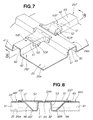
- FIG. 7 is a perspective view corresponding to FIG. 2 , but showing a modification of connecting members, floor frame and cross member;
- FIG. 8 is a cross-sectional view taken along line 8 - 8 of FIG. 7 ;
- FIG. 9 is an exploded perspective view showing the connecting members, floor frame and cross member of FIG. 7 .
- a vehicle body 11 (specifically, a vehicle body frame 11 ) of a vehicle 10 is composed of a monocoque body, as shown in FIG. 1 .
- the passenger compartment portion in the vehicle body 11 is composed of left and right side sills 21 , 21 extending in the longitudinal direction of the vehicle body 11 , a floor tunnel 22 extending in the longitudinal direction of the vehicle body 11 in the widthwise center of the vehicle 10 , two front and rear cross members 23 , 24 extending in the vehicle width direction so as to span between the left and right side sills 21 , 21 and the floor tunnel 22 , front floor panels 25 , 25 spread out between the left and right side sills 21 , 21 and the floor tunnel 22 and a plurality of floor frames 26 F, 26 R extending in the longitudinal direction of the vehicle body 11 to the left and right sides of the floor tunnel 22 .
- the rear cross members 24 are articles folded from steel sheets.
- the rear cross members 24 have a substantially inverted U shape in cross section, and flanges 34 , 35 extend sideways from the sides of the cross members, as shown in FIGS. 2 through 5 .
- the flanges 34 , 35 are bonded to top surfaces 25 a of the front floor panels 25 .
- the cross members 24 are each composed of a pair of left and right vertical walls 31 , 32 that rise from the top surfaces 25 a (one set of surfaces 25 a ) of the front floor panels 25 , top plates 33 that span between the top ends of the left and right vertical walls 31 , 32 , and the left and right flanges 34 , 35 which extend to the sides from the bottom ends of the left and right vertical walls 31 , 32 .
- the vertical walls 31 on the left side face toward the front of the vehicle body, and the vertical walls 32 on the right side face towards the rear of the vehicle body.
- the left vertical walls 31 are hereinbelow referred to as the “front vertical walls 31 ,” and the right vertical walls 32 are referred to as the “rear vertical walls 32 .”
- the front floor panels 25 are composed of steel sheets as shown in FIGS. 2 through 5 .
- the floor frames 26 F, 26 R swell upward from the top surfaces 25 a of the front floor panels 25 and form long, thin beads extending in the longitudinal direction of the vehicle body 11 . These beads are formed on the front floor panels 25 by embossing so as to swell upward from the top surfaces 25 a , and are shaped as grooves as seen from the underside of the front floor panels 25 .
- the floor frames 26 F, 26 R are formed into inverted U shapes in cross section, and are each composed of a pair of left and right vertical walls 41 , 42 that rise from the top surfaces 25 a of the front floor panels 25 , and top plates 43 that span between the top ends of the left and right vertical walls 41 , 42 .
- the plurality of floor frames 26 F, 26 R provided on the left side of the floor tunnel 22 are aligned in a straight row, sandwiching the rear cross member 24 at the front and rear sides.
- the plurality of floor frames 26 F, 26 R provided on the right side of the floor tunnel 22 are aligned in the same manner.
- the floor frames 26 F which are aligned to the front of the vehicle body with respect to the rear cross members 24 , are hereinbelow referred to as the “front floor frames 26 F,” and the floor frames 26 R aligned to the rear with respect to the vehicle body are referred to as the “rear floor frames 26 R.”
- Terminal ends 44 F of the front floor frames 26 F are positioned in proximity to the front vertical walls 31 in the cross members 24 .
- Terminal ends 44 R of the rear floor frames 26 R are positioned in proximity to the rear vertical walls 32 in the cross members 24 .
- the terminal ends 44 F, 44 R are the ends of the beads. The result is that in a plan view, the front terminal ends 44 F and the rear terminal ends 44 R are arranged in T shapes with respect to the cross members 24 .
- the spaces from distal ends 45 F of the front terminal ends 44 F to distal ends 45 R of the rear terminal ends 44 R are devoid of the floor frames 26 F, 26 R and are therefore flat, as shown in FIGS. 3 and 5 .
- the front and rear distal ends 45 F, 45 R are the same height as the top surfaces 25 a of the front floor panels 25 .
- the separation distance L 1 between the front and rear distal ends 45 F, 45 R is slightly greater than the outside width L 2 of the pairs of flanges 34 , 35 in the cross members 24 .
- Inclined top plates 46 that are inclined from the top plates 43 toward the distal ends 45 F extend from the front terminal ends 44 F.
- the rear terminal ends 44 R similarly have inclined top plates 46 .
- FIGS. 2 through 5 the bonding structure of the rear cross members 24 and the floor frames 26 F, 26 R will be described.
- the vertical walls 31 , 41 , 42 are joined together, as are the top plates 33 , 43 , by front connecting members 50 F.
- the vertical walls 32 , 41 , 42 are joined together, as are the top plates 33 , 43 , by rear connecting members 50 R.
- the front and rear connecting members 50 F, 50 R are iron and steel articles formed into T shapes in a plan view, and are composed of folded or cast steel sheets, for example.
- the front connecting members 50 F are integrally formed articles composed of top plates 51 having T shapes in a plan view, and pairs of left and right vertical walls 52 , 53 extending toward the front floor panels 25 from the sides of the stems of the top plates 51 .
- the top plates 51 are horizontal flat portions that join together the top plates 33 of the cross members 24 and the top plates 43 in the front terminal ends 44 F.
- the left and right vertical walls 52 , 53 join together the vertical walls 41 , 42 of the terminal ends 44 F and the front vertical walls 31 in the cross members 24 , and the left and right vertical walls 52 , 53 are formed into L shapes in a plan view.
- the rear connecting members 50 R are configured substantially the same as the front connecting members 50 F, and are longitudinally reversed from the front connecting members 50 F. Specifically, the top plates 51 in the rear connecting members 50 R join together the top plates 33 of the cross members 24 and the top plates 43 in the rear terminal ends 44 R. The left and right vertical walls 52 , 53 in the rear connecting members 50 R join together the rear vertical walls 32 in the cross members 24 and the vertical walls 41 , 42 in the terminal ends 44 R.
- the joining procedure using the front connecting members 50 F is as follows.
- the front connecting members 50 F are placed over the cross members 24 and the front terminal ends 44 F, which are disposed in T shapes in a plan view.
- top plates 51 of the connecting members 50 F are then joined to the top plates 33 of the cross members 24 , and the top plates 51 of the connecting members 50 F are joined to the top plates 43 of the terminal ends 44 F.
- the result is that the top plates 33 , 43 can be joined together by the top plates 51 of the connecting members 50 F.
- the vertical walls 52 , 53 of the connecting members 50 F are joined to the front vertical walls 31 of the cross members 24 , and the vertical walls 52 , 53 of the connecting members 50 F are joined to the vertical walls 41 , 42 in the terminal ends 44 F.
- the result is that the front vertical walls 31 and the vertical walls 41 , 42 of the terminal ends 44 F can be joined together by the vertical walls 52 , 53 of the connecting members 50 F.
- cross members 24 and the front terminal ends 44 F are joined together by the front connecting members 50 F.
- the rear connecting members 50 R are placed over the cross members 24 and the rear terminal ends 44 R, which are disposed in T shapes in a plan view.
- top plates 51 of the connecting members 50 R are then joined to the top plates 33 of the cross members 24 , and the top plates 51 of the connecting members 50 R are joined to the top plates 43 of the terminal ends 44 R.
- the result is that the top plates 33 , 43 can be joined together by the top plates 51 of the connecting members 50 R.
- the vertical walls 52 , 53 of the connecting members 50 R are joined to the rear vertical walls 32 of the cross members 24 , and the vertical walls 52 , 53 of the connecting members 50 R are joined to the vertical walls 41 , 42 in the terminal ends 44 R.
- the result is that the rear vertical walls 32 and the vertical walls 41 , 42 of the terminal ends 44 R can be joined together by the vertical walls 52 , 53 of the connecting members 50 R.
- the front and rear (plurality of) floor frames 26 F, 26 R composed of beads that are long and thin in the longitudinal direction of the vehicle body 11 are aligned in straight rows sandwiching the front and rear sides of the cross members 24 , the terminal ends 44 F, 44 R in the front and rear floor frames 26 F, 26 R are positioned in proximity to the cross members 24 , and the vertical walls 31 , 32 , 41 , 42 and top plates 33 , 43 in the terminal ends 44 F, 44 R and cross members 24 are joined together by the connecting members 50 F, 50 R which have T shapes in a plan view.
- the rigidity (including rigidity against loads in the vertical directions of the vehicle body 11 ) of the intersecting portions between the cross members 24 and the front and rear floor frames 26 F, 26 R can be increased by the connecting members 50 F, 50 R.
- the weight of the vehicle body 11 does not substantially increase because of a configuration merely in which the front and rear floor frames 26 F, 26 R composed of beads that are long and thin in the longitudinal direction of the vehicle body 11 are aligned in straight rows sandwiching the front and rear sides of the cross members 24 , and the cross members 24 and the terminal ends 44 F, 44 R in the front and rear floor frames 26 F, 26 R are joined together by the connecting members 50 F, 50 R which have T shapes in a plan view. In other words, rigidity can be increased while weight increases in the vehicle body 11 are suppressed.
- the cross members 24 have inverted U shapes, the cross members 24 are groove-shaped when viewed from below.
- the front vertical walls 31 and rear vertical walls 32 of the cross members 24 are connected to each other by two vertical ribs 61 , 61 aligned inside the grooves in the longitudinal direction of the cross members 24 .
- the two vertical ribs 61 , 61 are flat plates that are perpendicular in relation to the top surfaces 25 a of the front floor panels 25 , and are dividing walls (bulkheads) that partition the grooves of the cross members 24 in the longitudinal direction.
- the rigidity of the cross members 24 is increased by the two vertical ribs 61 , 61 .
- the rigidity of the cross members 24 is further increased if the vertical ribs 61 , 61 are also joined to the top plates 33 of the cross members 24 .
- the two vertical ribs 61 , 61 are disposed so as to be substantially continuous with the left and right vertical walls 41 , 42 in the front and rear floor frames, as shown in FIG. 4 . Therefore, the vertical walls 41 , 42 of the floor frames 26 F, 26 R, the vertical walls 52 , 53 of the connecting members 50 F, 50 R, and the vertical ribs 61 , 61 extend in a generally continuous manner along straight lines. Consequently, the rigidity (including the rigidity against loads in the vertical directions of the vehicle body) of the intersecting portions between the cross members 24 and the front and rear floor frames 26 F, 26 R can be further increased by the connecting members 50 F, 50 R.
- the weight of the vehicle body 11 does not substantially increase because of a configuration merely in which the front and rear floor frames 26 F, 26 R composed of beads that are long and thin in the longitudinal direction of the vehicle body are aligned in straight rows sandwiching the front and rear sides of the cross members 24 , the cross members 24 and the terminal ends 44 F, 44 R in the front and rear floor frames 26 F, 26 R are joined together by the connecting members 50 F, 50 R which have T shapes in a plan view, and the front and rear vertical walls 31 , 32 in the cross members 24 are connected by the two vertical ribs 61 , 61 .
- rigidity can be increased while weight increases in the vehicle body 11 are suppressed.
- FIGS. 1 through 5 The configuration in which the cross members 24 and the front and rear floor frames 26 F, 26 R are bonded by the connecting members 50 F, 50 R as shown in FIGS. 1 through 5 can be applied to other areas in the vehicle body 11 as shown in FIG. 6 .
- FIG. 6 shows an application example in which the connecting members shown in FIG. 1 are applied to other parts of the vehicle body 11 .
- the application example shows an example in which in a cargo space 71 in the rear of a vehicle 10 , cross members 24 and front and rear floor frames 26 F, 26 R are aligned to reinforce the bottom surface of rear floor panels 72 of the vehicle body 11 , and the cross members 24 and front and rear front floor frames 26 F, 26 R are bonded by connecting members 50 F, 50 R. According to the application example, a sufficient amount of space is ensured in the cargo space 71 , and lightweight and highly rigid rear floor panels 72 can be configured.
- FIGS. 7 through 9 show a modification of the cross members shown in FIGS. 1 through 5 . Components similar to those of the embodiment shown in FIGS. 1 through 5 are denoted by the same numerical symbols and are not described.
- the cross members 24 A of the modification are configured from beads formed integrally with front floor panels 25 , as are the floor frames 26 F, 26 R.
- the cross members 24 A of the modification are composed of pairs of left and right vertical walls 31 , 32 (front vertical walls 31 and rear vertical walls 32 ), and top plates 33 that span between the top ends of the left and right vertical walls 31 , 32 .
- cross members 24 A are configured from beads that swell upward from the front floor panels 25 and that are long and thin in the vehicle width direction, rigidity can be increased while weight increases in the vehicle body 11 are further suppressed.
- the material of the connecting members 50 F, 50 R is not limited to metal, and the connecting members may be resinous articles, for example.
Landscapes
- Engineering & Computer Science (AREA)
- Chemical & Material Sciences (AREA)
- Combustion & Propulsion (AREA)
- Transportation (AREA)
- Mechanical Engineering (AREA)
- Body Structure For Vehicles (AREA)
Abstract
Description
Claims (1)
Applications Claiming Priority (4)
| Application Number | Priority Date | Filing Date | Title |
|---|---|---|---|
| JP2007-277429 | 2007-10-25 | ||
| JP2007-277411 | 2007-10-25 | ||
| JP2007277411A JP5078546B2 (en) | 2007-10-25 | 2007-10-25 | Body structure |
| JP2007277429A JP5235067B2 (en) | 2007-10-25 | 2007-10-25 | Body structure |
Publications (2)
| Publication Number | Publication Date |
|---|---|
| US20090108633A1 US20090108633A1 (en) | 2009-04-30 |
| US7828370B2 true US7828370B2 (en) | 2010-11-09 |
Family
ID=40581906
Family Applications (1)
| Application Number | Title | Priority Date | Filing Date |
|---|---|---|---|
| US12/254,193 Expired - Fee Related US7828370B2 (en) | 2007-10-25 | 2008-10-20 | Vehicle body structure |
Country Status (1)
| Country | Link |
|---|---|
| US (1) | US7828370B2 (en) |
Cited By (12)
| Publication number | Priority date | Publication date | Assignee | Title |
|---|---|---|---|---|
| US20090206632A1 (en) * | 2008-02-19 | 2009-08-20 | Dr. Ing. H.C. F. Porsche Aktiengesellschaft | Central floor part of a vehicle body |
| US20090256339A1 (en) * | 2008-04-04 | 2009-10-15 | Christopher Mampe | Vehicle supplemental restraint system configuration and method |
| US20090289476A1 (en) * | 2008-04-24 | 2009-11-26 | Gm Global Technology Operations, Inc. | Frame structure for a motor vehicle |
| US20100026050A1 (en) * | 2008-08-04 | 2010-02-04 | Honda Motor Co., Ltd | Light weight devices and related methods for reinforcing an automotive roof assembly |
| US20100117394A1 (en) * | 2006-12-19 | 2010-05-13 | Dow Global Technologies, Inc. | Floor module including seating |
| US20100301637A1 (en) * | 2009-05-28 | 2010-12-02 | Honda Motor Co., Ltd. | Vehicle body rear part structure |
| US20130313860A1 (en) * | 2011-02-03 | 2013-11-28 | Teijin Limited | Vehicle Floor Structure |
| US20150003898A1 (en) * | 2012-03-06 | 2015-01-01 | Jfe Steel Corporation | Joint structure |
| US20150180078A1 (en) * | 2013-12-25 | 2015-06-25 | Toyota Jidosha Kabushiki Kaisha | Resin panel structure |
| US20170088177A1 (en) * | 2014-03-18 | 2017-03-30 | Renault S.A.S. | Rear structure of a motor vehicle |
| FR3096333A1 (en) | 2019-05-22 | 2020-11-27 | Psa Automobiles Sa | Front floor, fixing cross member for the front seat and vehicle comprising such elements |
| US20210178883A1 (en) * | 2019-12-16 | 2021-06-17 | Hyundai Motor Company | Vehicle floor structure |
Families Citing this family (17)
| Publication number | Priority date | Publication date | Assignee | Title |
|---|---|---|---|---|
| JP4407713B2 (en) * | 2007-03-30 | 2010-02-03 | 日産自動車株式会社 | Body structure |
| US7854472B2 (en) * | 2007-10-22 | 2010-12-21 | Honda Motor Co., Ltd. | Vehicle body structure |
| CN102001362B (en) * | 2009-08-27 | 2013-01-02 | 本田技研工业株式会社 | Vehicle body structure |
| WO2013028630A2 (en) * | 2011-08-19 | 2013-02-28 | Leroy Hagenbuch | An improved off-highway truck body floor design |
| CA2869625C (en) * | 2012-04-05 | 2016-02-23 | Nippon Sharyo, Ltd. | Rolling stock |
| JP6074155B2 (en) * | 2012-04-23 | 2017-02-01 | 川崎重工業株式会社 | Railway vehicle structure and rail vehicle including the same |
| FR3023251B1 (en) * | 2014-07-04 | 2018-01-19 | Psa Automobiles Sa. | IMPROVED CROSSROAD STRAP FOR SIDE SHOCK AND FRONT SHOCK |
| CL2016001847A1 (en) * | 2016-07-21 | 2017-02-10 | Minetec Sa | Transportable hopper in parts and assembly methods. |
| US20180065688A1 (en) * | 2016-09-07 | 2018-03-08 | Thunder Power New Energy Vehicle Development Compa ny Limited | Connection for the cross member and sill (pontoon) |
| CN108860320B (en) * | 2018-06-22 | 2020-11-17 | 江苏卡威汽车工业集团股份有限公司 | Lightweight automobile body structure of car |
| FR3086631B1 (en) * | 2018-10-01 | 2020-11-27 | Renault Sas | MODULAR DEVICE FOR REINFORCING A REAR FLOOR OF A MOTOR VEHICLE, IN A MOUNTING ZONE OF A UREA TANK |
| JP7107176B2 (en) * | 2018-11-08 | 2022-07-27 | トヨタ自動車株式会社 | vehicle underbody structure |
| DE102018129468A1 (en) * | 2018-11-22 | 2020-05-28 | Bombardier Transportation Gmbh | Envelope structure for a car body |
| US11208021B2 (en) * | 2019-10-25 | 2021-12-28 | Caterpillar Inc. | Haul truck dump body front wall support |
| KR20230042805A (en) * | 2021-09-23 | 2023-03-30 | 현대자동차주식회사 | Device for jointing members of vehicle |
| KR20240162919A (en) * | 2023-05-09 | 2024-11-18 | 현대자동차주식회사 | Floor panel |
| FR3156742B1 (en) * | 2023-12-15 | 2025-10-31 | Ampere Sas | Assembly for transferring longitudinal forces from a motor vehicle underbody |
Citations (15)
| Publication number | Priority date | Publication date | Assignee | Title |
|---|---|---|---|---|
| US1854710A (en) * | 1927-01-14 | 1932-04-19 | William G Mayer | Vehicle body and bumper |
| US3328935A (en) * | 1963-03-22 | 1967-07-04 | Renault | Shaped pieces with stamped ribs and reinforced junction points |
| US4462629A (en) * | 1981-11-11 | 1984-07-31 | Hitachi, Ltd. | Construction of car structure |
| JPH07291150A (en) | 1994-04-26 | 1995-11-07 | Honda Motor Co Ltd | Car floor |
| US5806918A (en) * | 1995-09-01 | 1998-09-15 | Honda Giken Kogyo Kabushiki Kaisha | Vehicle body structure |
| US5992921A (en) * | 1996-03-19 | 1999-11-30 | Toyota Jidosha Kabushiki Kaisha | Vehicle body structure |
| US6616217B1 (en) * | 1999-04-06 | 2003-09-09 | Expotech Limited | Vehicle pillar system |
| US6834912B2 (en) * | 2002-10-18 | 2004-12-28 | Honda Motor Co., Ltd. | Structure for controlled deformation of body side structure |
| US7014256B2 (en) * | 2003-01-16 | 2006-03-21 | Mazda Motor Corporation | Floor panel structure of vehicle body |
| US7500714B2 (en) * | 2007-06-19 | 2009-03-10 | Honda Motor Co., Ltd. | Vehicle body floor structure |
| US20090102238A1 (en) * | 2007-10-22 | 2009-04-23 | Honda Motor Co., Ltd. | Vehicle body structure |
| JP2009101772A (en) * | 2007-10-22 | 2009-05-14 | Honda Motor Co Ltd | Body structure |
| US7644978B2 (en) * | 2007-07-06 | 2010-01-12 | Nissan Motor Co., Ltd. | Vehicle floor structure for a motor vehicle |
| US20100078966A1 (en) * | 2007-06-19 | 2010-04-01 | Honda Motor Co., Ltd. | Vehicle body floor structure |
| US7690721B2 (en) * | 2003-08-13 | 2010-04-06 | Thyssenkrupp Steel Europe Ag | Junction structure for connecting two profiles in a vehicle support frame |
-
2008
- 2008-10-20 US US12/254,193 patent/US7828370B2/en not_active Expired - Fee Related
Patent Citations (15)
| Publication number | Priority date | Publication date | Assignee | Title |
|---|---|---|---|---|
| US1854710A (en) * | 1927-01-14 | 1932-04-19 | William G Mayer | Vehicle body and bumper |
| US3328935A (en) * | 1963-03-22 | 1967-07-04 | Renault | Shaped pieces with stamped ribs and reinforced junction points |
| US4462629A (en) * | 1981-11-11 | 1984-07-31 | Hitachi, Ltd. | Construction of car structure |
| JPH07291150A (en) | 1994-04-26 | 1995-11-07 | Honda Motor Co Ltd | Car floor |
| US5806918A (en) * | 1995-09-01 | 1998-09-15 | Honda Giken Kogyo Kabushiki Kaisha | Vehicle body structure |
| US5992921A (en) * | 1996-03-19 | 1999-11-30 | Toyota Jidosha Kabushiki Kaisha | Vehicle body structure |
| US6616217B1 (en) * | 1999-04-06 | 2003-09-09 | Expotech Limited | Vehicle pillar system |
| US6834912B2 (en) * | 2002-10-18 | 2004-12-28 | Honda Motor Co., Ltd. | Structure for controlled deformation of body side structure |
| US7014256B2 (en) * | 2003-01-16 | 2006-03-21 | Mazda Motor Corporation | Floor panel structure of vehicle body |
| US7690721B2 (en) * | 2003-08-13 | 2010-04-06 | Thyssenkrupp Steel Europe Ag | Junction structure for connecting two profiles in a vehicle support frame |
| US7500714B2 (en) * | 2007-06-19 | 2009-03-10 | Honda Motor Co., Ltd. | Vehicle body floor structure |
| US20100078966A1 (en) * | 2007-06-19 | 2010-04-01 | Honda Motor Co., Ltd. | Vehicle body floor structure |
| US7644978B2 (en) * | 2007-07-06 | 2010-01-12 | Nissan Motor Co., Ltd. | Vehicle floor structure for a motor vehicle |
| US20090102238A1 (en) * | 2007-10-22 | 2009-04-23 | Honda Motor Co., Ltd. | Vehicle body structure |
| JP2009101772A (en) * | 2007-10-22 | 2009-05-14 | Honda Motor Co Ltd | Body structure |
Cited By (21)
| Publication number | Priority date | Publication date | Assignee | Title |
|---|---|---|---|---|
| US20100117394A1 (en) * | 2006-12-19 | 2010-05-13 | Dow Global Technologies, Inc. | Floor module including seating |
| US20090206632A1 (en) * | 2008-02-19 | 2009-08-20 | Dr. Ing. H.C. F. Porsche Aktiengesellschaft | Central floor part of a vehicle body |
| US8342600B2 (en) * | 2008-02-19 | 2013-01-01 | Dr. Ing. H.C.F. Porsche Aktiengesellschaft | Central floor part of a vehicle body |
| US20090256339A1 (en) * | 2008-04-04 | 2009-10-15 | Christopher Mampe | Vehicle supplemental restraint system configuration and method |
| US8113541B2 (en) * | 2008-04-04 | 2012-02-14 | Honda Motor Co., Ltd. | Vehicle supplemental restraint system configuration and method |
| US8287035B2 (en) * | 2008-04-24 | 2012-10-16 | GM Global Technology Operations LLC | Frame structure for a motor vehicle |
| US20090289476A1 (en) * | 2008-04-24 | 2009-11-26 | Gm Global Technology Operations, Inc. | Frame structure for a motor vehicle |
| US20100026050A1 (en) * | 2008-08-04 | 2010-02-04 | Honda Motor Co., Ltd | Light weight devices and related methods for reinforcing an automotive roof assembly |
| US8087717B2 (en) * | 2008-08-04 | 2012-01-03 | Honda Motor Co., Ltd. | Light weight devices and related methods for reinforcing an automotive roof assembly |
| US20100301637A1 (en) * | 2009-05-28 | 2010-12-02 | Honda Motor Co., Ltd. | Vehicle body rear part structure |
| US8070217B2 (en) * | 2009-05-28 | 2011-12-06 | Honda Motor Co., Ltd. | Vehicle body rear part structure |
| US20130313860A1 (en) * | 2011-02-03 | 2013-11-28 | Teijin Limited | Vehicle Floor Structure |
| US8814255B2 (en) * | 2011-02-03 | 2014-08-26 | Teijin Limited | Vehicle floor structure |
| US20150003898A1 (en) * | 2012-03-06 | 2015-01-01 | Jfe Steel Corporation | Joint structure |
| US20150180078A1 (en) * | 2013-12-25 | 2015-06-25 | Toyota Jidosha Kabushiki Kaisha | Resin panel structure |
| US9755262B2 (en) * | 2013-12-25 | 2017-09-05 | Toyota Jidosha Kabushiki Kaisha | Resin panel structure |
| US20170088177A1 (en) * | 2014-03-18 | 2017-03-30 | Renault S.A.S. | Rear structure of a motor vehicle |
| US9809252B2 (en) * | 2014-03-18 | 2017-11-07 | Renault S.A.S. | Rear structure of a motor vehicle |
| FR3096333A1 (en) | 2019-05-22 | 2020-11-27 | Psa Automobiles Sa | Front floor, fixing cross member for the front seat and vehicle comprising such elements |
| US20210178883A1 (en) * | 2019-12-16 | 2021-06-17 | Hyundai Motor Company | Vehicle floor structure |
| US11813933B2 (en) * | 2019-12-16 | 2023-11-14 | Hyundai Motor Company | Vehicle floor structure |
Also Published As
| Publication number | Publication date |
|---|---|
| US20090108633A1 (en) | 2009-04-30 |
Similar Documents
| Publication | Publication Date | Title |
|---|---|---|
| US7828370B2 (en) | Vehicle body structure | |
| US7854472B2 (en) | Vehicle body structure | |
| JP4272626B2 (en) | Lower body structure | |
| US9281505B2 (en) | Battery mounting structure for vehicle | |
| US6962389B2 (en) | Vehicle body structure | |
| US20100156146A1 (en) | Floor structure for vehicle body | |
| US9643655B2 (en) | Vehicle side portion structure | |
| KR102107967B1 (en) | A Joint Material for Chassis Frame and Variable type Chassis Module of Vehicle using the same | |
| CN112441137B (en) | Front body structure of the vehicle | |
| US7325865B2 (en) | Vehicle rear body structure | |
| US10549787B2 (en) | Vehicle body floor structure | |
| KR100333294B1 (en) | Frame for bus applied center space frame | |
| CN112441136B (en) | Front body structure of the vehicle | |
| JP7310458B2 (en) | Vehicle front body structure | |
| US20110175400A1 (en) | Vehicle front structure | |
| JP2009107424A (en) | Body structure | |
| US10112650B2 (en) | Vehicle frame assembly | |
| US10745056B2 (en) | Front pillar for a vehicle body | |
| US10501125B2 (en) | Vehicle body rear portion structure | |
| CN111572649B (en) | Body-in-white structure | |
| CN108791505B (en) | Roof structure | |
| CN220391349U (en) | Suspension mounting structure and vehicle | |
| JP2009101772A (en) | Body structure | |
| JP5078546B2 (en) | Body structure | |
| CN209888934U (en) | Rear wall assembly and vehicle with same |
Legal Events
| Date | Code | Title | Description |
|---|---|---|---|
| AS | Assignment |
Owner name: HONDA MOTOR CO., LTD., JAPAN Free format text: ASSIGNMENT OF ASSIGNORS INTEREST;ASSIGNORS:OHI, YOSHIAKI;GOMI, TETSUYA;REEL/FRAME:021706/0298 Effective date: 20081009 |
|
| STCF | Information on status: patent grant |
Free format text: PATENTED CASE |
|
| FEPP | Fee payment procedure |
Free format text: PAYOR NUMBER ASSIGNED (ORIGINAL EVENT CODE: ASPN); ENTITY STATUS OF PATENT OWNER: LARGE ENTITY |
|
| FPAY | Fee payment |
Year of fee payment: 4 |
|
| MAFP | Maintenance fee payment |
Free format text: PAYMENT OF MAINTENANCE FEE, 8TH YEAR, LARGE ENTITY (ORIGINAL EVENT CODE: M1552) Year of fee payment: 8 |
|
| FEPP | Fee payment procedure |
Free format text: MAINTENANCE FEE REMINDER MAILED (ORIGINAL EVENT CODE: REM.); ENTITY STATUS OF PATENT OWNER: LARGE ENTITY |
|
| LAPS | Lapse for failure to pay maintenance fees |
Free format text: PATENT EXPIRED FOR FAILURE TO PAY MAINTENANCE FEES (ORIGINAL EVENT CODE: EXP.); ENTITY STATUS OF PATENT OWNER: LARGE ENTITY |
|
| STCH | Information on status: patent discontinuation |
Free format text: PATENT EXPIRED DUE TO NONPAYMENT OF MAINTENANCE FEES UNDER 37 CFR 1.362 |
|
| FP | Lapsed due to failure to pay maintenance fee |
Effective date: 20221109 |