EP2011686A2 - Container securing device - Google Patents
Container securing device Download PDFInfo
- Publication number
- EP2011686A2 EP2011686A2 EP08159156A EP08159156A EP2011686A2 EP 2011686 A2 EP2011686 A2 EP 2011686A2 EP 08159156 A EP08159156 A EP 08159156A EP 08159156 A EP08159156 A EP 08159156A EP 2011686 A2 EP2011686 A2 EP 2011686A2
- Authority
- EP
- European Patent Office
- Prior art keywords
- container
- housing portion
- flap
- beverage container
- securing device
- Prior art date
- Legal status (The legal status is an assumption and is not a legal conclusion. Google has not performed a legal analysis and makes no representation as to the accuracy of the status listed.)
- Granted
Links
Images





Classifications
-
- B—PERFORMING OPERATIONS; TRANSPORTING
- B60—VEHICLES IN GENERAL
- B60N—SEATS SPECIALLY ADAPTED FOR VEHICLES; VEHICLE PASSENGER ACCOMMODATION NOT OTHERWISE PROVIDED FOR
- B60N3/00—Arrangements or adaptations of other passenger fittings, not otherwise provided for
- B60N3/10—Arrangements or adaptations of other passenger fittings, not otherwise provided for of receptacles for food or beverages, e.g. refrigerated
- B60N3/105—Arrangements or adaptations of other passenger fittings, not otherwise provided for of receptacles for food or beverages, e.g. refrigerated for receptables of different size or shape
- B60N3/106—Arrangements or adaptations of other passenger fittings, not otherwise provided for of receptacles for food or beverages, e.g. refrigerated for receptables of different size or shape with adjustable clamping mechanisms
-
- B—PERFORMING OPERATIONS; TRANSPORTING
- B60—VEHICLES IN GENERAL
- B60N—SEATS SPECIALLY ADAPTED FOR VEHICLES; VEHICLE PASSENGER ACCOMMODATION NOT OTHERWISE PROVIDED FOR
- B60N3/00—Arrangements or adaptations of other passenger fittings, not otherwise provided for
- B60N3/10—Arrangements or adaptations of other passenger fittings, not otherwise provided for of receptacles for food or beverages, e.g. refrigerated
- B60N3/101—Arrangements or adaptations of other passenger fittings, not otherwise provided for of receptacles for food or beverages, e.g. refrigerated fixed
-
- Y—GENERAL TAGGING OF NEW TECHNOLOGICAL DEVELOPMENTS; GENERAL TAGGING OF CROSS-SECTIONAL TECHNOLOGIES SPANNING OVER SEVERAL SECTIONS OF THE IPC; TECHNICAL SUBJECTS COVERED BY FORMER USPC CROSS-REFERENCE ART COLLECTIONS [XRACs] AND DIGESTS
- Y10—TECHNICAL SUBJECTS COVERED BY FORMER USPC
- Y10S—TECHNICAL SUBJECTS COVERED BY FORMER USPC CROSS-REFERENCE ART COLLECTIONS [XRACs] AND DIGESTS
- Y10S224/00—Package and article carriers
- Y10S224/926—Vehicle attached carrier for beverage container or bottle
Definitions
- the present invention relates to a container securing device, including a housing portion with a cylindrical shape, an upper end whereof is opened, to house a container, such as a beverage container, and a flap, positioned so as to be moved within a hole that is formed in a cylindrical wall of the housing portion, which secures the beverage container within the housing portion.
- a container securing device is conventionally known, such as is depicted in FIG. 8A , which includes a housing portion 2, wherein a beverage container 103 is inserted, and a diameter compensation element; i.e., a flap, 1, which is capable of a hinged swinging movement, either forward or backward, in a depression portion 2b of a surrounding wall 2a of the housing 2, and which secures the beverage container 103 in the housing portion 2 by causing a leading end portion 1a of the diameter compensation element 1 to protrude into the housing portion 2, a spring (not shown) that impels the diameter compensation element to swing in a counterclockwise direction, and a ratchet mechanism (not shown) that allows the hinged swinging movement in a clockwise direction of the diameter compensation element 1, and checks the hinged swinging movement in the counterclockwise direction thereof, at each of a plurality of prescribed angles, for instance, at 20 degrees, 40 degrees, and 60 degrees refer, for instance, to Japanese Patent Application Laid-Open No. 2003-237452 for
- the diameter compensation element 1 is impelled by the spring, such the a tapering constriction component 103c of the beverage container 103 is impressed upon the leading end portion 1a of the diameter compensation element 1, with a result that the beverage container 103 is secured within the housing portion 2, such as is depicted in FIG. 8C .
- the diameter compensation element 1 When extracting the beverage container 103 from the housing portion 2, when the beverage container 103 is in a state such as is depicted in FIG. 8C , the diameter compensation element 1 catches upon a widening component 103b of the beverage container 103, making it difficult to extract the beverage container 103 from the housing portion 2 as a consequence thereof
- the diameter compensation element 1 does not swing in a left hand direction, i.e., in the counterclockwise direction, beyond the prescribed angle, forcibly extracting the beverage container 103 from the housing portion 2 may result in a breakage of the diameter compensation element 1 or the ratchet mechanism, owing to the leading end portion 1a of the diameter compensation element 1 catching upon the widening component 103b of the beverage container 103.
- An object of the present invention is to provide a container securing device that is capable of a) reliably securing even a container with a tapering constriction component thereof and b) allowing the container to be easily extracted, without being caught upon a widening component thereof.
- a container securing device includes a housing portion with a cylindrical shape, an upper end whereof is opened, to house a container, and a flap, positioned within a hole that is formed in a cylindrical wall of the housing portion, so as to be capable of moving either into, or out of the housing portion, in response to an insertion of the container into the housing portion, or an extraction of the container from the housing portion.
- the flap When the container is fully housed within the housing portion, the flap is capable of moving to a location that secures the container therein.
- FIG. 1 depicts a container securing device according to the present invention; as an instance, according to an embodiment wherein a container securing device accordance to the present invention is applied to an automobile.
- a center console 1000 of an approximately rectangular shape, and which is positioned in an interior of the automobile (not shown), such as is depicted in FIG. 1 , comprises such as a compartment 101, which is a rectangular box that is formed within an approximate center portion of the center console 1000, and an armrest 102, which is installed in a portion of the center console 1000 to a rear of the compartment 101, on a change of elevation therefrom, and which opens and closes on a support of an axle (not shown).
- a pair of container securing devices 100, 100 according to the present invention is fitted into an upper opening of the compartment 101.
- Each respective container securing device 100 comprises, as an instance, a housing portion 20, which is formed from a cylindrical body, and which is open at an upper end thereof, in order to house a container, as an instance, a beverage container 103 (refer to FIGs. 7A to 7C ), a panel portion 10 that is installed in an upper portion of the housing portion 20,and a securing mechanism 200 that is installed in an outer portion of an exterior cylindrical wall 21d of the housing portion 20, such as is depicted in FIG. 2 .
- each respective component that configures the container securing device 100 prefferably be formed of essentially any material that does not deform as a result of an effect of a heat that would be transmitted thereto from the beverage container 103. It would be desirable to use a material that does not suffer heat shrinkage.
- the panel portion 10 comprises the two housing portions 20, 20, a flange 11 (partially not shown) that is formed as a single unit with the upper end of the two housing portions 20, 20 (only one thereof shown), and a rib 12, which extends in a downward direction from four edge portions 11a of the flange 11.
- the flange 11 is formed in a shape that is nearly identical to the shape of the upper opening of the compartment, 101 of the center console 1000, such as is depicted in FIG. 1 . Fitting the container securing devices 100, 100 into the compartment 101 brings the rib 12 of the flange 11 into contact with an interior wall 101a (refer to FIG. 1 ) of the compartment 101.
- a hole 21a is formed in each respective housing portion 20, in an immediate vicinity of an upper opening 21b thereof, and which protrudes into in the cylindrical wall 21d thereof, such as is depicted in FIG. 2 and FIG. 3 .
- an inner diameter thereof inclines gradually from an upper opening end 21c of the housing portion 20, narrowing toward a base wall 21e thereof such as is depicted in FIG. 2B .
- An under surface 21f of the base wall 21e of each respective housing portion 20 comes into contact with a base wall of the compartment 101, and the container securing device 100 is supported within the compartment 101 (not shown).
- the securing mechanism 200 comprises a guide portion 30, which extends from the cylindrical wall 21d toward an exterior thereof, in a diameter direction, a flap 40, which is placed within the guide portion 30 so as to be movable, i.e., in a left to right direction in FIG. 2B , a pin 70, which is placed in a center shoe portion 31Af. 31Bf, (see FIG. 4A ) of the guide portion 30, and an impelling component 60, which impels the flap 40 into an interior portion, of the housing portion 20.
- the impelling component thereof is formed from a coiled spring, as an instance thereof.
- the guide portion 30 comprises a pair of side panels 31A, 31B, which are formed in an approximate "E" shape, with a relative mutual facing thereof, and a substrate 32, which mutually links the side panels 31A, 31B, via a lower portion thereof, such as is depicted in FIG. 4A and FIG. 4B .
- Each respective side panel 31A, 31B comprises an upper shoe portion 31Ae, 31Be, the center shoe portion 31Af, 31Bf, which is formed, in an approximate semicircular are shape, a lower shoe portion 31Ag, 31Bg, and a linking portion 31Al, 31Bl which links the respective shoe portions thereof.
- a crevice 31Ae, 31Ad, 13Bc, 31Bd is respectively formed between each respective upper shoe portion, and each respective central shoe portion, and between each respective central shoe portion and each respective lower shoe portion.
- the side panels 31A, 31B connect to the exterior surface of the cylindrical wall 21d, in a location that constricts the hole 21a of the cylindrical wall 21d.
- a separation distance between the side panels 31A, 31B is set so as to be approximately identical with a width dimension of the hole 21a.
- an upper surface 31Aa, 31Ba, of the side panels 31A, 31B is in a location that is higher than an upper edge of the hole 21a
- a lower surface 31Am, 31Bm, of the side panels 31A, 31B is in a location that is lower than a lower edge of the hole 21a.
- the width dimension of the hole 21a is set so as to be approximately identical with a width dimension of the flap 40, and a height dimension of the hole 21a is set so as to be larger than the width dimension of the flap 40.
- An axle loop 31Afa, 31Bfa is formed within each respective center shoe portion 31Af, 31Bf, such as is depicted in FIG. 4A , and the pin 70 passes through the axle loops 31Afa, 31BE such as is depicted in FIG. 4B .
- a height dimension of the crevices 31Ac, 31Bc, and of the crevices 31Ad, 31Bd is respectively set to be a degree larger than a diameter of a first axle 41 and a second axle 42 of the flap 40 (to be described hereinafter).
- the flap 40 prises a pair of panels 51, 52, which are mutually, spaced apart, and which exhibit a "C" shape when viewed side on, the first axle 41 and the second axle 42, which penetrate an upper protrusion portion 51a 52a, and a lower protrusion portion 51b, 52b, of the panels 51, 52, and a linking portion 53, which links a leading end portion of the panel 51 and a leading end portion of the panel 52, such as is depicted in FIG. 9 through FIG. 11 .
- a circular arc portion of a right hand side of the flap 40 constitutes a leading end 40a, as depicted in FIG. 11 .
- a length of the first axle 41 and the second axle 42 is set to be approximately identical to a width W32 of the guide portion 30 (refer to FIG. 12 ).
- the flap 40 enters into a space between the hole 21a of the housing portion 20, and the side panels 31A, 31B of the guide portion 30, and the leading end 40a of the flap 40 protrudes into the interior portion of the housing portion 20, such as is depicted in FIG. 3 .
- the first axle 41 enters into the crevices 31Ac, 31Bc of the guide portion 30, is capable of movement in line with the crevices 31Ac, 31Bc thereof, and is supported by an upper surface of the center shoe portion 31Af, 31Bf, such as is depicted in FIG. 4B .
- the second, axle 42 also enters into the crevices 31Ad, 31Bd of the guide portion 30, is capable of movement in line with the crevices 31Ad, 31Bd thereof, and is supported by an upper surface of the lower shoe portion 31Ag, 31Bg, in a manner similar to that of the first axle 41. It is thus possible for the flap 40 to swing in a hinged manner, around the first axle 41 or the second axle 42.
- the flap 40 is guided in a forward and reverse direction with respect to the housing portion 20 by the side panels 31A, 31B of the guide portion 30, such as is depicted in FIG. 3 , and the leading end 40a of the flap 40 protrudes into the interior portion of the housing portion 20, wherein the leading end 40a thereof makes contact with a side surface 103 of the beverage container 103, such as is depicted in FIGs. 7A to 7C .
- the coiled spring 60 is configured from a pair of arm portions in a straight line shape 60a, 60b, and a main spring body in a spiral shape 60c.
- the coiled. spring main body 60c is attached to the pin 70, and the pair of arm portions 60a, 60b, of the coiled spring 60 extend from the coiled spring main body 60c in an approximately straight line shape, i.e., in an upper and a lower direction in FIG. 5 , come into contact with the first axle 41 and the second axle 42, and impel the first axle 41 and the second axis 42 toward the housing portion 20, i.e., toward a laft hand side thereof in FIG. 5 .
- the flap 40 When the beverage container 103 is not housed, the flap 40 is impelled by an impelling force of the coiled spring 60 into the interior of the housing portion 20, and the leading end 40a of the flap 40 is caused to protrude into the interior space of the housing portion 20, such as is depicted in FIG. 6A .
- the widening component 103b of a surface 103a of the beverage container 103 comes into contact with the leading end 40a of the flap 40, and impresses the flap 40 in a direction, that is denoted by an arrow S1, such as is depicted in FIG. 6B and FIG. 7A
- the flap 40 swings, i.e., fluctuates, in a counterclockwise direction revolving around the first axle 41, resisting the impelling force of the coiled spring 60, and is propelled into the hole 21a of the cylindrical wall 21d of the housing portion 20.
- the flap 40 is being constantly impelled toward the housing portion 20 by the coiled spring 60, further inserting the beverage container 103 into the housing portion 20 causes the leading end 40a of the flap 40 to make a rubbing contact upon the tapering constriction component 103c of the beverage container 103.
- the flap 40 being impelled toward the housing portion 20 by the coiled spring 60, swings, i.e., fluctuates, in a clockwise direction revolving around the second axle 42, while also being propelled toward the interior of the housing portion 20 (refer to FIG. 7B ).
- the leading end 40a of the flap 40 comes into contact with the tapering constriction component 103c of the beverage container 103, without catching upon the widening component 103b of the beverage container 103, and it is possible to secure the beverage container 103 thereby. As a consequence thereof it is possible to reliably fix the beverage container 103 within the housing portion 20.
- Lifting the beverage container 103 from the housing portion 20 when extracting the beverage container 103 causes the leading end 40a of the flap 40, which is in contact with the tapering constriction component 103c of the beverage container 103, to be impressed in an upward direction S2, and to make a rubbing contact in the direction of the widening component 103b thereof
- the rubbing contact thereof causes the flap 40 to swing, i.e., to fluctuate, in the counterclockwise direction revolving around the second axle 42, resisting the impelling force of the coiled spring 60, and the leading end 40a of the flap 40 is thereby propelled into the hole 21a of the housing portion 20.
- the flap 40 is being constantly impelled toward the housing portion 20 by the coiled spring 60, further lifting the beverage container 103 causes the leading end 40a of the flap 40 to move beyond the widening component 103b of the beverage container 103, and to make a rubbing contact in the direction of a lower portion 103d thereof.
- the flap 40 swings in the counterclockwise direction revolving around the second axle 42, and is also propelled toward the interior of the housing portion 20, thereby returning to an initial state wherein the beverage container 103 is not housed,
- the flap 40 it is possible for the flap 40 to fluctuate smoothly, because the center shoe portion 31Af, 31Bf is formed in the approximate semicircular arc shape, such as is depicted in FIG. 4B .
- the flap 40 fluctuates in accordance with a shape of the tapering constriction component 103c of the beverage container 103 when the beverage container 103 is extracted in the manner described herein, it is possible to reliably secure the tapering constriction component 103c of the beverage container 103 without catching upon the widening component 103b of the beverage container 103, and to reliably fix the beverage container 103 within the housing portion 20 thereby.
- a typical device that secures a beverage container is installed so as to be capable of swinging within the inner wall of the housing portion that houses the beverage container, or within a location that corresponds to the inner wall of the housing portion that houses the beverage container, the securing mechanism thereof is exposed in its entirety in many instances, and the swinging motion of the securing mechanism may be inhibited as a beverage fluid adheres to, and degrades, a swinging hinge base portion of the securing mechanism.
- the fact that such a. securing mechanism is typically exposed is not considered particularly suitable from a standpoint of vehicle compartment design. The present invention resolves such problems as the foregoing, in addition to the problems described herein.
- the flap fluctuates in accordance with a shape of the widening component of the beverage container when the beverage container is extracted, it is possible to smoothly extract the beverage container, without the flap catching upon the widening component of the beverage container.
Landscapes
- Engineering & Computer Science (AREA)
- Physics & Mathematics (AREA)
- Thermal Sciences (AREA)
- Transportation (AREA)
- Mechanical Engineering (AREA)
- Passenger Equipment (AREA)
- Vehicle Step Arrangements And Article Storage (AREA)
- Details Of Rigid Or Semi-Rigid Containers (AREA)
Abstract
Description
- The present invention, relates to a container securing device, including a housing portion with a cylindrical shape, an upper end whereof is opened, to house a container, such as a beverage container, and a flap, positioned so as to be moved within a hole that is formed in a cylindrical wall of the housing portion, which secures the beverage container within the housing portion.
- A container securing device is conventionally known, such as is depicted in
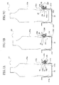
FIG. 8A , which includes ahousing portion 2, wherein abeverage container 103 is inserted, and a diameter compensation element; i.e., a flap, 1, which is capable of a hinged swinging movement, either forward or backward, in adepression portion 2b of a surroundingwall 2a of thehousing 2, and which secures thebeverage container 103 in thehousing portion 2 by causing a leadingend portion 1a of thediameter compensation element 1 to protrude into thehousing portion 2, a spring (not shown) that impels the diameter compensation element to swing in a counterclockwise direction, and a ratchet mechanism (not shown) that allows the hinged swinging movement in a clockwise direction of thediameter compensation element 1, and checks the hinged swinging movement in the counterclockwise direction thereof, at each of a plurality of prescribed angles, for instance, at 20 degrees, 40 degrees, and 60 degrees refer, for instance, to Japanese Patent Application Laid-Open No.2003-237452 - As an instance with respect to the conventional container securing device, such as is depicted in
FIG. 8B , inserting thebeverage container 103, which has a tapering constriction therein, into thehousing portion 2 by way of an opening at an upper end thereof, alower portion 103d of thebeverage container 103 comes into contact with the leadingend portion 1a of thediameter compensation element 1, resisting an impelling form of the spring element (not shown), and thereby causing thediameter compensation element 1 to swing in the clockwise direction. Furthermore, when thebeverage container 103 is inserted thereinto, thediameter compensation element 1 is impelled by the spring, such the a taperingconstriction component 103c of thebeverage container 103 is impressed upon the leadingend portion 1a of thediameter compensation element 1, with a result that thebeverage container 103 is secured within thehousing portion 2, such as is depicted inFIG. 8C . - When extracting the
beverage container 103 from thehousing portion 2, when thebeverage container 103 is in a state such as is depicted inFIG. 8C , thediameter compensation element 1 catches upon awidening component 103b of thebeverage container 103, making it difficult to extract thebeverage container 103 from thehousing portion 2 as a consequence thereof In addition, whereas, owing to the ratchet mechanism, thediameter compensation element 1 does not swing in a left hand direction, i.e., in the counterclockwise direction, beyond the prescribed angle, forcibly extracting thebeverage container 103 from thehousing portion 2 may result in a breakage of thediameter compensation element 1 or the ratchet mechanism, owing to the leadingend portion 1a of thediameter compensation element 1 catching upon the wideningcomponent 103b of thebeverage container 103. - An object of the present invention is to provide a container securing device that is capable of a) reliably securing even a container with a tapering constriction component thereof and b) allowing the container to be easily extracted, without being caught upon a widening component thereof.
- In order to accomplish the above object, a container securing device according to an embodiment of the present invention includes a housing portion with a cylindrical shape, an upper end whereof is opened, to house a container, and a flap, positioned within a hole that is formed in a cylindrical wall of the housing portion, so as to be capable of moving either into, or out of the housing portion, in response to an insertion of the container into the housing portion, or an extraction of the container from the housing portion.
- When the container is fully housed within the housing portion, the flap is capable of moving to a location that secures the container therein.
-
- FIG. is an oblique view that depicts a center console within an automobile whereto is applied a container securing device according to an embodiment of the present invention.
-
FIG. 2A is a partial cutaway oblique view of the container securing device that is depicted inFIG. 1 . -
FIG. 2B is a cutaway view of the container securing device that is depicted inFIG. 1 . -
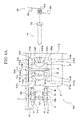
FIG. 3 is an oblique view that depicts a key portion of the container securing device that is depicted in eitherFIG. 2A or FIG. 2B . -
FIG. 4A is an exploded view of the key portion of the container securing device that is depicted in eitherFIG. 2A or FIG. 2B . -
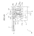
FIG. 4B depicts a key portion of the container securing device that is depicted in eitherFIG. 2A or FIG. 2B . -
FIG. 5A is an oblique cutaway view that depicts a cutaway of the key portion of the container securing device that is depicted in eitherFIG. 2A or FIG. 2B and that is obtained along a line A-A that is denoted inFIG. 4B . -
FIG. 5B is an oblique cutaway view that depicts a cutaway of the key portion of the container securing device that is depicted in eitherFIG. 2A or FIG. 2B and that is obtained along a line A-A that is denoted inFIG. 4B . -
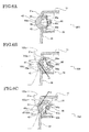
FIGs. 6A to 6C are cutaway views that describe an operation of the container securing device according to the embodiment. -
FIGs. 7A to 7C are cutaway views that describe an operation of the container securing device according to the embodiment. -
FIGS. 8A to 8C are cutaway views that describe an operation of a conventional container securing device. -
FIG. 9 is a cutaway view that depicts a flap of the container securing device that is depicted inFIG. 4 . -
FIG. 10 is a cutaway view of the flap of the container securing device that is depicted inFIG. 4A . -
FIG. 11 is an elevation view of the flap of the container securing device that is depicted inFIG. 4A . -
FIG. 12 is a rear view of the key portion of the container securing device that is depicted inFIG. 4B . - Preferred embodiments of the present invention will be explained in detail hereinafter, with reference to the accompanying drawings.
-
FIG. 1 depicts a container securing device according to the present invention; as an instance, according to an embodiment wherein a container securing device accordance to the present invention is applied to an automobile. - According to the embodiment, a
center console 1000, of an approximately rectangular shape, and which is positioned in an interior of the automobile (not shown), such as is depicted inFIG. 1 , comprises such as acompartment 101, which is a rectangular box that is formed within an approximate center portion of thecenter console 1000, and anarmrest 102, which is installed in a portion of thecenter console 1000 to a rear of thecompartment 101, on a change of elevation therefrom, and which opens and closes on a support of an axle (not shown). - A pair of
container securing devices compartment 101. - Each respective
container securing device 100 comprises, as an instance, ahousing portion 20, which is formed from a cylindrical body, and which is open at an upper end thereof, in order to house a container, as an instance, a beverage container 103 (refer toFIGs. 7A to 7C ), apanel portion 10 that is installed in an upper portion of thehousing portion 20,and asecuring mechanism 200 that is installed in an outer portion of an exteriorcylindrical wall 21d of thehousing portion 20, such as is depicted inFIG. 2 . - It would be permissible for each respective component that configures the container securing
device 100 to be formed of essentially any material that does not deform as a result of an effect of a heat that would be transmitted thereto from thebeverage container 103. It would be desirable to use a material that does not suffer heat shrinkage. - The
panel portion 10 comprises the twohousing portions housing portions 20, 20 (only one thereof shown), and arib 12, which extends in a downward direction from fouredge portions 11a of theflange 11. - The
flange 11 is formed in a shape that is nearly identical to the shape of the upper opening of the compartment, 101 of thecenter console 1000, such as is depicted inFIG. 1 . Fitting thecontainer securing devices compartment 101 brings therib 12 of theflange 11 into contact with aninterior wall 101a (refer toFIG. 1 ) of thecompartment 101. - A
hole 21a is formed in eachrespective housing portion 20, in an immediate vicinity of anupper opening 21b thereof, and which protrudes into in thecylindrical wall 21d thereof, such as is depicted inFIG. 2 andFIG. 3 . - With respect to an interior surface of the
housing portion 20, an inner diameter thereof inclines gradually from anupper opening end 21c of thehousing portion 20, narrowing toward abase wall 21e thereof such as is depicted inFIG. 2B . An undersurface 21f of thebase wall 21e of eachrespective housing portion 20 comes into contact with a base wall of thecompartment 101, and thecontainer securing device 100 is supported within the compartment 101 (not shown). - The
securing mechanism 200 comprises aguide portion 30, which extends from thecylindrical wall 21d toward an exterior thereof, in a diameter direction, aflap 40, which is placed within theguide portion 30 so as to be movable, i.e., in a left to right direction inFIG. 2B , apin 70, which is placed in a center shoe portion 31Af. 31Bf, (seeFIG. 4A ) of theguide portion 30, and animpelling component 60, which impels theflap 40 into an interior portion, of thehousing portion 20. The impelling component thereof is formed from a coiled spring, as an instance thereof. - The
guide portion 30 comprises a pair ofside panels substrate 32, which mutually links theside panels FIG. 4A andFIG. 4B . Eachrespective side panel side panels cylindrical wall 21d, in a location that constricts thehole 21a of thecylindrical wall 21d. - A separation distance between the
side panels hole 21a. In addition, an upper surface 31Aa, 31Ba, of theside panels hole 21a, and a lower surface 31Am, 31Bm, of theside panels hole 21a. - In addition, the width dimension of the
hole 21a is set so as to be approximately identical with a width dimension of theflap 40, and a height dimension of thehole 21a is set so as to be larger than the width dimension of theflap 40. - An axle loop 31Afa, 31Bfa is formed within each respective center shoe portion 31Af, 31Bf, such as is depicted in
FIG. 4A , and thepin 70 passes through the axle loops 31Afa, 31BE such as is depicted inFIG. 4B . In addition a height dimension of the crevices 31Ac, 31Bc, and of the crevices 31Ad, 31Bd, is respectively set to be a degree larger than a diameter of afirst axle 41 and asecond axle 42 of the flap 40 (to be described hereinafter). - The
flap 40 prises a pair ofpanels first axle 41 and thesecond axle 42, which penetrate anupper 52a, and aprotrusion portion 51alower protrusion portion panels portion 53, which links a leading end portion of thepanel 51 and a leading end portion of thepanel 52, such as is depicted inFIG. 9 through FIG. 11 . A circular arc portion of a right hand side of theflap 40 constitutes aleading end 40a, as depicted inFIG. 11 . - A length of the
first axle 41 and thesecond axle 42 is set to be approximately identical to a width W32 of the guide portion 30 (refer toFIG. 12 ). - In addition, the
flap 40 enters into a space between thehole 21a of thehousing portion 20, and theside panels guide portion 30, and theleading end 40a of theflap 40 protrudes into the interior portion of thehousing portion 20, such as is depicted inFIG. 3 . - The
first axle 41 enters into the crevices 31Ac, 31Bc of theguide portion 30, is capable of movement in line with the crevices 31Ac, 31Bc thereof, and is supported by an upper surface of the center shoe portion 31Af, 31Bf, such as is depicted inFIG. 4B . In addition, the second,axle 42 also enters into the crevices 31Ad, 31Bd of theguide portion 30, is capable of movement in line with the crevices 31Ad, 31Bd thereof, and is supported by an upper surface of the lower shoe portion 31Ag, 31Bg, in a manner similar to that of thefirst axle 41. It is thus possible for theflap 40 to swing in a hinged manner, around thefirst axle 41 or thesecond axle 42. - In addition, the
flap 40 is guided in a forward and reverse direction with respect to thehousing portion 20 by theside panels guide portion 30, such as is depicted inFIG. 3 , and theleading end 40a of theflap 40 protrudes into the interior portion of thehousing portion 20, wherein theleading end 40a thereof makes contact with aside surface 103 of thebeverage container 103, such as is depicted inFIGs. 7A to 7C . - The
coiled spring 60 is configured from a pair of arm portions in astraight line shape spiral shape 60c. The coiled. springmain body 60c is attached to thepin 70, and the pair ofarm portions spring 60 extend from the coiled springmain body 60c in an approximately straight line shape, i.e., in an upper and a lower direction inFIG. 5 , come into contact with thefirst axle 41 and thesecond axle 42, and impel thefirst axle 41 and thesecond axis 42 toward thehousing portion 20, i.e., toward a laft hand side thereof inFIG. 5 . - Following is a description of an operation of the
container securing device 100, according to the description herein. - When the
beverage container 103 is not housed, theflap 40 is impelled by an impelling force of the coiledspring 60 into the interior of thehousing portion 20, and theleading end 40a of theflap 40 is caused to protrude into the interior space of thehousing portion 20, such as is depicted inFIG. 6A . - When the
beverage container 103 is inserted via theupper opening 21b of thehousing portion 20, the wideningcomponent 103b of asurface 103a of thebeverage container 103 comes into contact with theleading end 40a of theflap 40, and impresses theflap 40 in a direction, that is denoted by an arrow S1, such as is depicted inFIG. 6B andFIG. 7A As a consequence, theflap 40 swings, i.e., fluctuates, in a counterclockwise direction revolving around thefirst axle 41, resisting the impelling force of the coiledspring 60, and is propelled into thehole 21a of thecylindrical wall 21d of thehousing portion 20. - Given that the
flap 40 is being constantly impelled toward thehousing portion 20 by the coiledspring 60, further inserting thebeverage container 103 into thehousing portion 20 causes theleading end 40a of theflap 40 to make a rubbing contact upon thetapering constriction component 103c of thebeverage container 103. In such a circumstance, theflap 40, being impelled toward thehousing portion 20 by the coiledspring 60, swings, i.e., fluctuates, in a clockwise direction revolving around thesecond axle 42, while also being propelled toward the interior of the housing portion 20 (refer toFIG. 7B ). As a consequence thereof, theleading end 40a of theflap 40 comes into contact with the taperingconstriction component 103c of thebeverage container 103, without catching upon the wideningcomponent 103b of thebeverage container 103, and it is possible to secure thebeverage container 103 thereby. As a consequence thereof it is possible to reliably fix thebeverage container 103 within thehousing portion 20. - Lifting the
beverage container 103 from thehousing portion 20 when extracting thebeverage container 103 causes theleading end 40a of theflap 40, which is in contact with the taperingconstriction component 103c of thebeverage container 103, to be impressed in an upward direction S2, and to make a rubbing contact in the direction of the wideningcomponent 103b thereof The rubbing contact thereof causes theflap 40 to swing, i.e., to fluctuate, in the counterclockwise direction revolving around thesecond axle 42, resisting the impelling force of the coiledspring 60, and theleading end 40a of theflap 40 is thereby propelled into thehole 21a of thehousing portion 20. - Given that the
flap 40 is being constantly impelled toward thehousing portion 20 by the coiledspring 60, further lifting thebeverage container 103 causes theleading end 40a of theflap 40 to move beyond the wideningcomponent 103b of thebeverage container 103, and to make a rubbing contact in the direction of alower portion 103d thereof. In such a circumstance, theflap 40 swings in the counterclockwise direction revolving around thesecond axle 42, and is also propelled toward the interior of thehousing portion 20, thereby returning to an initial state wherein thebeverage container 103 is not housed, - In addition, it is possible for the
flap 40 to fluctuate smoothly, because the center shoe portion 31Af, 31Bf is formed in the approximate semicircular arc shape, such as is depicted inFIG. 4B . - Given that the
flap 40 fluctuates when thebeverage container 103 is extracted, such as is depicted inFIGS. 7A to 7C , it is possible to smoothly extract thebeverage container 103, without theflap 40 catching upon thetapering constriction component 103c of thebeverage container 103. As a consequence thereof, no risk exists that theflap 40 will be damaged thereby. - Given that the
flap 40 fluctuates in accordance with a shape of thetapering constriction component 103c of thebeverage container 103 when thebeverage container 103 is extracted in the manner described herein, it is possible to reliably secure thetapering constriction component 103c of thebeverage container 103 without catching upon the wideningcomponent 103b of thebeverage container 103, and to reliably fix thebeverage container 103 within thehousing portion 20 thereby. - Given that a typical device that secures a beverage container is installed so as to be capable of swinging within the inner wall of the housing portion that houses the beverage container, or within a location that corresponds to the inner wall of the housing portion that houses the beverage container, the securing mechanism thereof is exposed in its entirety in many instances, and the swinging motion of the securing mechanism may be inhibited as a beverage fluid adheres to, and degrades, a swinging hinge base portion of the securing mechanism. In addition, the fact that such a. securing mechanism is typically exposed is not considered particularly suitable from a standpoint of vehicle compartment design. The present invention resolves such problems as the foregoing, in addition to the problems described herein.
- It is possible to extract a beverage container by way of the container securing device according to the present invention without causing the flap to catch upon a side surface widening component of the beverage container.
- As an instance thereof, given that the flap fluctuates in accordance with a shape of the widening component of the beverage container when the beverage container is extracted, it is possible to smoothly extract the beverage container, without the flap catching upon the widening component of the beverage container.
- Although the preferred embodiments of the present invention have been described herein, it should be understood that the present invention is not limited to the embodiments described herein, and that various modifications and changes can be made to the embodiments.
Claims (4)
- A container securing device, comprising:a housing portion (20) configured to house a container (103), with a cylindrical shape, and opened at an upper end thereof,a flap (40) configured to be positioned within a hole that is formed within a surrounding wall (21d) of the housing portion (20), and to be installed so as to be capable of moving either out of the housing portion, or into the housing portion, in response to the container being inserted into, or extracted from, the housing portion; andan impelling component (60) configured to impel the flap toward an interior direction of the housing unit;wherein:the flap (40) is capable of moving to a location that secures the container when the container is fully housed within, the housing portion.
- The container securing device according to claim 1, wherein:a portion of the flap (40) that makes contact with the container is formed in an approximately semicircular shape.
- The container securing device according to claim 1, wherein:the flap further comprises a first and a second axle (41, 42), which are positioned in either a direction of an insertion of the container into the housing portion, or a direction of a removal of the container from the housing portion, with an interval placed therebetween;wherein:the impelling component (60) impels the first and second axles toward the interior direction of the housing unit; andthe flap (40) is configured so as to be capable of fluctuating revolving around either of the first or the second axle.
- The container securing device according to claim 2, wherein:the flap (40) further comprises a first and a second axle (41, 42), which are positioned in either a direction of an insertion of the container (103) into the housing portion (20), or a direction of a removal of the container from the housing portion, with an interval placed therebetween;wherein:the impelling component (60) impels the first and second axles toward the interior direction of the housing unit; andthe flap (40) is configured so as to be capable of fluctuating revolving around either of the first or the second axle.
Applications Claiming Priority (1)
| Application Number | Priority Date | Filing Date | Title |
|---|---|---|---|
| JP2007173903A JP5154849B2 (en) | 2007-07-02 | 2007-07-02 | Drink container holding mechanism |
Publications (3)
| Publication Number | Publication Date |
|---|---|
| EP2011686A2 true EP2011686A2 (en) | 2009-01-07 |
| EP2011686A3 EP2011686A3 (en) | 2012-07-04 |
| EP2011686B1 EP2011686B1 (en) | 2016-08-24 |
Family
ID=39790324
Family Applications (1)
| Application Number | Title | Priority Date | Filing Date |
|---|---|---|---|
| EP08159156.2A Ceased EP2011686B1 (en) | 2007-07-02 | 2008-06-27 | Container securing device |
Country Status (4)
| Country | Link |
|---|---|
| US (1) | US7748679B2 (en) |
| EP (1) | EP2011686B1 (en) |
| JP (1) | JP5154849B2 (en) |
| CN (1) | CN101337521A (en) |
Cited By (1)
| Publication number | Priority date | Publication date | Assignee | Title |
|---|---|---|---|---|
| DE102009017235A1 (en) | 2009-04-09 | 2010-10-14 | Fischer Automotive Systems Gmbh & Co. Kg | Holder for a beverage container, comprises an open top container receptacle in which the beverage container is adjustable from the top, a holding element, a guide, an elastic ring and a housing in which the holding element is implemented |
Families Citing this family (11)
| Publication number | Priority date | Publication date | Assignee | Title |
|---|---|---|---|---|
| JP6338932B2 (en) * | 2014-05-28 | 2018-06-06 | カルソニックカンセイ株式会社 | Cup holder |
| JP2016078585A (en) * | 2014-10-15 | 2016-05-16 | 豊田合成株式会社 | Container holder |
| DE102015002669B4 (en) | 2015-03-02 | 2021-09-30 | Audi Ag | Storage device for arrangement in a motor vehicle |
| US10506890B2 (en) * | 2016-03-11 | 2019-12-17 | Toyoda Gosei Co., Ltd. | Cup holder |
| KR101795284B1 (en) * | 2016-07-04 | 2017-11-07 | 현대자동차주식회사 | Cup holder and manufacturing method thereof |
| JP6321242B2 (en) * | 2017-03-03 | 2018-05-09 | カルソニックカンセイ株式会社 | Cup holder |
| US10086736B1 (en) | 2017-03-28 | 2018-10-02 | Ford Global Technologies, Llc | Cup holder assembly having stabilizers |
| JP6873172B2 (en) * | 2019-02-13 | 2021-05-19 | 森六テクノロジー株式会社 | Beverage container holding device |
| JP7470664B2 (en) * | 2021-07-14 | 2024-04-18 | 本田技研工業株式会社 | Container holding structure |
| JP1772948S (en) * | 2023-11-24 | 2024-06-13 | ||
| USD1103067S1 (en) * | 2023-11-28 | 2025-11-25 | Jaguar Land Rover Limited | Vehicle center console |
Citations (3)
| Publication number | Priority date | Publication date | Assignee | Title |
|---|---|---|---|---|
| US20050279752A1 (en) | 2004-06-17 | 2005-12-22 | Nifco Inc. | Container holding unit and cup holder device |
| DE102005038683A1 (en) | 2004-08-24 | 2006-03-09 | Hyundai Motor Co. | Cup holder for vehicles |
| DE102005044358A1 (en) | 2004-10-02 | 2006-04-13 | Hyundai Motor Co. | Cup holder for vehicles |
Family Cites Families (12)
| Publication number | Priority date | Publication date | Assignee | Title |
|---|---|---|---|---|
| DE29606583U1 (en) * | 1996-04-11 | 1997-10-09 | Bayerische Motoren Werke AG, 80809 München | Holder for a beverage container |
| US5782448A (en) * | 1996-07-09 | 1998-07-21 | Ldm Technologies, Inc. | Apparatus for supporting a container |
| JP3706536B2 (en) * | 2000-05-12 | 2005-10-12 | 小島プレス工業株式会社 | Vehicle article holding device |
| DE20108250U1 (en) * | 2001-05-16 | 2002-09-19 | fischerwerke Artur Fischer GmbH & Co. KG, 72178 Waldachtal | Cup holder for a tailored bottle |
| DE10161122C2 (en) * | 2001-12-12 | 2003-10-23 | Preh Elektro Feinmechanik | Holder for hollow vessels, in particular for beverage containers |
| DE10206267A1 (en) | 2002-02-15 | 2003-08-28 | Fischer Automotive Sys Gmbh | Holder for a beverage container |
| DE20219606U1 (en) * | 2002-12-18 | 2004-04-29 | Fischer Automotive Systems Gmbh | Holder for a beverage container |
| US6705580B1 (en) * | 2002-12-20 | 2004-03-16 | Daimlerchrysler Corporation | Cup holder for a motor vehicle |
| JP2005349959A (en) * | 2004-06-10 | 2005-12-22 | Inoac Corp | Container holder |
| JP4275101B2 (en) * | 2004-06-11 | 2009-06-10 | 小島プレス工業株式会社 | Vehicle storage device |
| KR100569342B1 (en) * | 2004-08-16 | 2006-04-07 | 현대자동차주식회사 | Cup holder support structure for automobile |
| JP2007084022A (en) * | 2005-09-26 | 2007-04-05 | Toyota Motor Corp | Vehicle cup holder |
-
2007
- 2007-07-02 JP JP2007173903A patent/JP5154849B2/en not_active Expired - Fee Related
-
2008
- 2008-06-27 EP EP08159156.2A patent/EP2011686B1/en not_active Ceased
- 2008-07-01 US US12/216,225 patent/US7748679B2/en not_active Expired - Fee Related
- 2008-07-02 CN CNA200810127831XA patent/CN101337521A/en active Pending
Patent Citations (3)
| Publication number | Priority date | Publication date | Assignee | Title |
|---|---|---|---|---|
| US20050279752A1 (en) | 2004-06-17 | 2005-12-22 | Nifco Inc. | Container holding unit and cup holder device |
| DE102005038683A1 (en) | 2004-08-24 | 2006-03-09 | Hyundai Motor Co. | Cup holder for vehicles |
| DE102005044358A1 (en) | 2004-10-02 | 2006-04-13 | Hyundai Motor Co. | Cup holder for vehicles |
Cited By (1)
| Publication number | Priority date | Publication date | Assignee | Title |
|---|---|---|---|---|
| DE102009017235A1 (en) | 2009-04-09 | 2010-10-14 | Fischer Automotive Systems Gmbh & Co. Kg | Holder for a beverage container, comprises an open top container receptacle in which the beverage container is adjustable from the top, a holding element, a guide, an elastic ring and a housing in which the holding element is implemented |
Also Published As
| Publication number | Publication date |
|---|---|
| US7748679B2 (en) | 2010-07-06 |
| CN101337521A (en) | 2009-01-07 |
| JP2009012515A (en) | 2009-01-22 |
| EP2011686B1 (en) | 2016-08-24 |
| JP5154849B2 (en) | 2013-02-27 |
| EP2011686A3 (en) | 2012-07-04 |
| US20090045309A1 (en) | 2009-02-19 |
Similar Documents
| Publication | Publication Date | Title |
|---|---|---|
| EP2011686A2 (en) | Container securing device | |
| US20180371808A1 (en) | Interior apparatus of a vehicle | |
| JP2006144537A (en) | Push latch | |
| CN100473569C (en) | Safe air bag module | |
| US20030116988A1 (en) | Vehicle interior panel having compartment and swing door | |
| EP1164459A2 (en) | Computer panel member | |
| JP2656766B2 (en) | Holding device used for beverage containers | |
| KR20200034860A (en) | Fuel door apparatus for vehicle | |
| US6543822B1 (en) | Self-presenting secondary hood latch assembly | |
| KR101393285B1 (en) | Door checker for vehicle | |
| US11260800B2 (en) | Vehicle interior component | |
| US7646879B2 (en) | Headset communication unit | |
| JP2000110425A (en) | Opener device | |
| WO2021085595A1 (en) | Lock lever and opening/closing device | |
| KR100396584B1 (en) | Arm stopper device of opening part | |
| US6853545B2 (en) | Structure for guiding flexible printed wiring board through a hinge portion between a body and a swingable member | |
| JP2005113402A (en) | Finger padding prevention device for hinged door | |
| JP5028153B2 (en) | Push latch device and cabinet using the same | |
| JP3187771B2 (en) | Handle mechanism | |
| JP4999445B2 (en) | Console hinge structure | |
| KR20050120271A (en) | Center facia tray locking device of an automobile | |
| JP7730742B2 (en) | Baggage claim box | |
| JP7457641B2 (en) | inside handle device | |
| KR100427214B1 (en) | Center console for vehicles | |
| US11591828B2 (en) | Handle device |
Legal Events
| Date | Code | Title | Description |
|---|---|---|---|
| PUAI | Public reference made under article 153(3) epc to a published international application that has entered the european phase |
Free format text: ORIGINAL CODE: 0009012 |
|
| 17P | Request for examination filed |
Effective date: 20080627 |
|
| AK | Designated contracting states |
Kind code of ref document: A2 Designated state(s): AT BE BG CH CY CZ DE DK EE ES FI FR GB GR HR HU IE IS IT LI LT LU LV MC MT NL NO PL PT RO SE SI SK TR |
|
| AX | Request for extension of the european patent |
Extension state: AL BA MK RS |
|
| PUAL | Search report despatched |
Free format text: ORIGINAL CODE: 0009013 |
|
| AK | Designated contracting states |
Kind code of ref document: A3 Designated state(s): AT BE BG CH CY CZ DE DK EE ES FI FR GB GR HR HU IE IS IT LI LT LU LV MC MT NL NO PL PT RO SE SI SK TR |
|
| AX | Request for extension of the european patent |
Extension state: AL BA MK RS |
|
| RIC1 | Information provided on ipc code assigned before grant |
Ipc: B60N 3/10 20060101AFI20120530BHEP |
|
| AKX | Designation fees paid |
Designated state(s): DE FR GB |
|
| 17Q | First examination report despatched |
Effective date: 20130426 |
|
| GRAP | Despatch of communication of intention to grant a patent |
Free format text: ORIGINAL CODE: EPIDOSNIGR1 |
|
| INTG | Intention to grant announced |
Effective date: 20160322 |
|
| GRAS | Grant fee paid |
Free format text: ORIGINAL CODE: EPIDOSNIGR3 |
|
| GRAA | (expected) grant |
Free format text: ORIGINAL CODE: 0009210 |
|
| RAP1 | Party data changed (applicant data changed or rights of an application transferred) |
Owner name: CALSONIC KANSEI CORPORATION |
|
| RIN1 | Information on inventor provided before grant (corrected) |
Inventor name: KIKUCHI, MASAMI |
|
| AK | Designated contracting states |
Kind code of ref document: B1 Designated state(s): DE FR GB |
|
| REG | Reference to a national code |
Ref country code: GB Ref legal event code: FG4D |
|
| REG | Reference to a national code |
Ref country code: DE Ref legal event code: R096 Ref document number: 602008045838 Country of ref document: DE |
|
| REG | Reference to a national code |
Ref country code: FR Ref legal event code: PLFP Year of fee payment: 10 |
|
| REG | Reference to a national code |
Ref country code: DE Ref legal event code: R097 Ref document number: 602008045838 Country of ref document: DE |
|
| PLBE | No opposition filed within time limit |
Free format text: ORIGINAL CODE: 0009261 |
|
| STAA | Information on the status of an ep patent application or granted ep patent |
Free format text: STATUS: NO OPPOSITION FILED WITHIN TIME LIMIT |
|
| 26N | No opposition filed |
Effective date: 20170526 |
|
| REG | Reference to a national code |
Ref country code: FR Ref legal event code: PLFP Year of fee payment: 11 |
|
| PGFP | Annual fee paid to national office [announced via postgrant information from national office to epo] |
Ref country code: DE Payment date: 20180612 Year of fee payment: 11 |
|
| PGFP | Annual fee paid to national office [announced via postgrant information from national office to epo] |
Ref country code: FR Payment date: 20180511 Year of fee payment: 11 |
|
| PGFP | Annual fee paid to national office [announced via postgrant information from national office to epo] |
Ref country code: GB Payment date: 20180627 Year of fee payment: 11 |
|
| REG | Reference to a national code |
Ref country code: DE Ref legal event code: R119 Ref document number: 602008045838 Country of ref document: DE |
|
| GBPC | Gb: european patent ceased through non-payment of renewal fee |
Effective date: 20190627 |
|
| PG25 | Lapsed in a contracting state [announced via postgrant information from national office to epo] |
Ref country code: GB Free format text: LAPSE BECAUSE OF NON-PAYMENT OF DUE FEES Effective date: 20190627 Ref country code: DE Free format text: LAPSE BECAUSE OF NON-PAYMENT OF DUE FEES Effective date: 20200101 |
|
| PG25 | Lapsed in a contracting state [announced via postgrant information from national office to epo] |
Ref country code: FR Free format text: LAPSE BECAUSE OF NON-PAYMENT OF DUE FEES Effective date: 20190630 |