EP2011684A2 - Operator's seat for heavy equipment having optimized switch arrangements for controlling the equipment - Google Patents
Operator's seat for heavy equipment having optimized switch arrangements for controlling the equipment Download PDFInfo
- Publication number
- EP2011684A2 EP2011684A2 EP08011971A EP08011971A EP2011684A2 EP 2011684 A2 EP2011684 A2 EP 2011684A2 EP 08011971 A EP08011971 A EP 08011971A EP 08011971 A EP08011971 A EP 08011971A EP 2011684 A2 EP2011684 A2 EP 2011684A2
- Authority
- EP
- European Patent Office
- Prior art keywords
- operator
- seat
- switches
- switch
- control lever
- Prior art date
- Legal status (The legal status is an assumption and is not a legal conclusion. Google has not performed a legal analysis and makes no representation as to the accuracy of the status listed.)
- Granted
Links
- XLYOFNOQVPJJNP-UHFFFAOYSA-N water Substances O XLYOFNOQVPJJNP-UHFFFAOYSA-N 0.000 description 4
- CDBYLPFSWZWCQE-UHFFFAOYSA-L Sodium Carbonate Chemical compound [Na+].[Na+].[O-]C([O-])=O CDBYLPFSWZWCQE-UHFFFAOYSA-L 0.000 description 3
- 238000007792 addition Methods 0.000 description 1
- 235000013361 beverage Nutrition 0.000 description 1
- 238000010276 construction Methods 0.000 description 1
- 230000004048 modification Effects 0.000 description 1
- 238000012986 modification Methods 0.000 description 1
- 229910052705 radium Inorganic materials 0.000 description 1
- HCWPIIXVSYCSAN-UHFFFAOYSA-N radium atom Chemical compound [Ra] HCWPIIXVSYCSAN-UHFFFAOYSA-N 0.000 description 1
- 238000006467 substitution reaction Methods 0.000 description 1
Images


Classifications
-
- B60K35/10—
-
- E—FIXED CONSTRUCTIONS
- E02—HYDRAULIC ENGINEERING; FOUNDATIONS; SOIL SHIFTING
- E02F—DREDGING; SOIL-SHIFTING
- E02F9/00—Component parts of dredgers or soil-shifting machines, not restricted to one of the kinds covered by groups E02F3/00 - E02F7/00
- E02F9/16—Cabins, platforms, or the like, for drivers
-
- B—PERFORMING OPERATIONS; TRANSPORTING
- B60—VEHICLES IN GENERAL
- B60K—ARRANGEMENT OR MOUNTING OF PROPULSION UNITS OR OF TRANSMISSIONS IN VEHICLES; ARRANGEMENT OR MOUNTING OF PLURAL DIVERSE PRIME-MOVERS IN VEHICLES; AUXILIARY DRIVES FOR VEHICLES; INSTRUMENTATION OR DASHBOARDS FOR VEHICLES; ARRANGEMENTS IN CONNECTION WITH COOLING, AIR INTAKE, GAS EXHAUST OR FUEL SUPPLY OF PROPULSION UNITS IN VEHICLES
- B60K20/00—Arrangement or mounting of change-speed gearing control devices in vehicles
- B60K20/02—Arrangement or mounting of change-speed gearing control devices in vehicles of initiating means
- B60K20/08—Dashboard means
-
- B—PERFORMING OPERATIONS; TRANSPORTING
- B60—VEHICLES IN GENERAL
- B60N—SEATS SPECIALLY ADAPTED FOR VEHICLES; VEHICLE PASSENGER ACCOMMODATION NOT OTHERWISE PROVIDED FOR
- B60N2/00—Seats specially adapted for vehicles; Arrangement or mounting of seats in vehicles
- B60N2/75—Arm-rests
- B60N2/79—Adaptations for additional use of the arm-rests
- B60N2/797—Adaptations for additional use of the arm-rests for use as electrical control means, e.g. switches
-
- B—PERFORMING OPERATIONS; TRANSPORTING
- B60—VEHICLES IN GENERAL
- B60N—SEATS SPECIALLY ADAPTED FOR VEHICLES; VEHICLE PASSENGER ACCOMMODATION NOT OTHERWISE PROVIDED FOR
- B60N3/00—Arrangements or adaptations of other passenger fittings, not otherwise provided for
- B60N3/10—Arrangements or adaptations of other passenger fittings, not otherwise provided for of receptacles for food or beverages, e.g. refrigerated
- B60N3/101—Arrangements or adaptations of other passenger fittings, not otherwise provided for of receptacles for food or beverages, e.g. refrigerated fixed
-
- E—FIXED CONSTRUCTIONS
- E02—HYDRAULIC ENGINEERING; FOUNDATIONS; SOIL SHIFTING
- E02F—DREDGING; SOIL-SHIFTING
- E02F9/00—Component parts of dredgers or soil-shifting machines, not restricted to one of the kinds covered by groups E02F3/00 - E02F7/00
-
- B—PERFORMING OPERATIONS; TRANSPORTING
- B60—VEHICLES IN GENERAL
- B60Y—INDEXING SCHEME RELATING TO ASPECTS CROSS-CUTTING VEHICLE TECHNOLOGY
- B60Y2200/00—Type of vehicle
- B60Y2200/40—Special vehicles
- B60Y2200/41—Construction vehicles, e.g. graders, excavators
- B60Y2200/412—Excavators
Definitions
- the present invention relates to an operator's seat for heavy equipment having optimized switch arrangements for controlling the equipment, in which various kinds of switches that are frequently operated by an operator sitting in the operator's seat are arranged in closest proximity to a control lever within a range in which the switches do not interfere with the control lever in operation, and thus physical inconvenience and fatigue that the operator who operates the corresponding switches for a long time suffers can be reduced.
- the present invention relates to an operator's seat for heavy equipment having optimized switch arrangements for controlling the equipment, in which arrangements of various kinds of switches and components of operating devices that are frequently used by an operator in the seat due to the characteristic of the equipment are integrated within a radius that an operator's hand reaches (i.e. in a hand arm operation zone), and thus physical inconvenience and fatigue that the operator who repeatedly operates working devices for a long time suffers can be reduced.
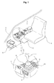
- an ash tray 3 is detachably installed on a front surface of a console box 2 on which a control lever 1, and a cup holder 6 for receiving a beverage container (e.g., a soda can, a water bottle, or the like) is installed on a side panel 5 of a cab.
- a beverage container e.g., a soda can, a water bottle, or the like
- An engine RPM mode switch 7 and various kinds of operating switches 8 are installed on the side panel 5, and a display mode switch 9 and an instrument cluster 10 are installed on the console box 2.
- the cup holder 6, which is arranged in front of the control lever 1, is positioned outside a hand arm operation zone (which is a zone where operator's arm and hand are situated when an operator extends his/her arm to operate the above-described switches).
- the display mode switch 9 and the instrument cluster 10 are arranged in a body on the console box 2, the operator sitting in the seat 4 should lower his/her head to confirm and operate the display mode switch 9 and the instrument cluster 10 whenever he/she changes a working mode of the equipment.
- the present invention has been made to solve the above-mentioned problems occurring in the prior art while advantages achieved by the prior art are maintained intact.
- One object of the present invention is to provide an operator's seat for heavy equipment having optimized switch arrangements for controlling the equipment, in which arrangements of various kinds of switches and components of operating devices that are frequently used by an operator in the seat due to the characteristic of the equipment are integrated within a radius that an operator's hand reaches, and thus physical inconvenience and fatigue that the operator who operates the corresponding switches suffers can be minimized.
- an operator's seat for heavy equipment having optimized switch arrangements for controlling the equipment which includes a switch instrument installed within a radius that a hand of an operator sitting in the operator's seat reaches; a control lever mounted on a specified position of the switch instrument to control operations of working devices; and switches arranged on the switch instrument in closest proximity to the control lever so that the operator in the operator's seat can operate the switches in the closest position in which the operator does not invade a control stroke zone of the control lever.
- the switches may include at least one of an engine RPM mode switch, operating switches of the equipment, and a display mode switch.
- the operator's seat for heavy equipment may further include a cup holder installed in a specified position of the switch instrument.
- control lever and the switches may be installed in a hand arm operation zone of the operator in the operator's seat.
- the control lever may be mounted on the switch instrument toward the operator in the operator's seat, the engine RPM mode switch may be arranged on the right side of the control lever, the operating switches may be arranged in front of the engine RPM mode switch, and the display mode switch may be arranged at the rear of the engine RPM mode switch.
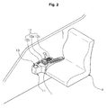
- an operator's seat for heavy equipment having optimized switch arrangements for controlling the equipment includes a switch instrument 11 installed within a radius that a hand of an operator sitting in the operator's seat 4 reaches (i.e. in a hand arm operation zone Z as indicated in FIG. 4 ); a control lever (RCV lever) mounted on a specified position of the switch instrument 11 to control operations of working devices such as a boom, an arm, and the like; and various kinds of switches 12 arranged on the switch instrument 11 in closest proximity to the control lever 1 so that the operator in the operator's seat 4 can operate the switches 12 in the closest position in which the operator does not invade a control stroke zone of the control lever 1.
- a switch instrument 11 installed within a radius that a hand of an operator sitting in the operator's seat 4 reaches (i.e. in a hand arm operation zone Z as indicated in FIG. 4 ); a control lever (RCV lever) mounted on a specified position of the switch instrument 11 to control operations of working devices such as a boom, an arm, and the like; and various kinds
- the switches 12 include at least one of an engine RPM mode switch 12a, operating switches 12b of the equipment, and a display mode switch 12c.
- the operator's seat 4 for heavy equipment further includes a cup holder 13 installed in a specified position of the switch instrument 11 to receive therein a soda can, a water bottle, or the like.
- control lever 1 and the switches 12 are installed in a hand arm operation zone Z of the operator in the operator's seat 4.
- the control lever 1 is mounted on the switch instrument 11 toward the operator in the operator's seat 4, the engine RPM mode switch 12a is arranged on the right side of the control lever 1, the operating switches 12b are arranged in front of the engine RPM mode switch 12a, and the display mode switch 12c is arranged at the rear of the engine RPM mode switch 12a.
- the heavy equipment such as an excavator possesses the characteristics that it repeats the same working mode for a long time in the same working place.
- the operator sitting in the operator's seat drives working devices such as a boom and so on by easily operating the control lever 1 and various kinds of switches 12 mounted on the switch instrument 11 that is installed within a radium that the operator's hand reaches, so that an excavating work is repeatedly performed.
- the operator can easily use a water bottle and so on received in the cup holder 13 installed in front of the switch instrument 11. That is, since the switch instrument 11 is installed within a radius Z that the hand of the operator in the operator's seat reaches, the operator can easily draw out the water bottle and so on received in the cup holder 13 by extending his/her arm during working.
- the switch instrument 11 in which the control lever 1 and various kinds of switches 12 that are frequently operated by the operator in the operator's during the working is installed in the optimal position in the radius that the operator's hand reaches.
- the switches 12 are arranged in closest proximity to the control lever 1 without invading the control stroke zone of the control lever 1 (i.e., the switches 12 are arranged in a specified position in closest proximity to the control lever 1 as they get out of the stroke zone of the control lever 1). Accordingly, the operator's body is prevented from touching the control lever 1 through the operator's carelessness when the operator in the operator's seat operates the switches 12, and this causes the corresponding working device to operate contrary to the operator's intention.
- the instrument cluster 14 comes in sight of the operator. Accordingly, the operator can confirm the display state of the instrument cluster 14 as he/she looks at the front working device.
- the operator sitting in the seat 4 should lower his/her head to confirm and operate the display mode switch 9 as illustrated in FIG. 1B , and this causes operator fatigue to be increased.
- an operator's seat for heavy equipment having optimized switch arrangements for controlling the equipment according to the embodiment of the present invention has the following advantages.
Abstract
Description
- This application is based on and claims priority from Korean Patent Application No.
10-2007-0067992, filed on July 6, 2007 - The present invention relates to an operator's seat for heavy equipment having optimized switch arrangements for controlling the equipment, in which various kinds of switches that are frequently operated by an operator sitting in the operator's seat are arranged in closest proximity to a control lever within a range in which the switches do not interfere with the control lever in operation, and thus physical inconvenience and fatigue that the operator who operates the corresponding switches for a long time suffers can be reduced.
- More particularly, the present invention relates to an operator's seat for heavy equipment having optimized switch arrangements for controlling the equipment, in which arrangements of various kinds of switches and components of operating devices that are frequently used by an operator in the seat due to the characteristic of the equipment are integrated within a radius that an operator's hand reaches (i.e. in a hand arm operation zone), and thus physical inconvenience and fatigue that the operator who repeatedly operates working devices for a long time suffers can be reduced.
- As illustrated in
FIG. 1 , according to a conventional operator's seat for heavy equipment, anash tray 3 is detachably installed on a front surface of aconsole box 2 on which acontrol lever 1, and acup holder 6 for receiving a beverage container (e.g., a soda can, a water bottle, or the like) is installed on aside panel 5 of a cab. - An engine
RPM mode switch 7 and various kinds ofoperating switches 8 are installed on theside panel 5, and a display mode switch 9 and aninstrument cluster 10 are installed on theconsole box 2. - The
cup holder 6, which is arranged in front of thecontrol lever 1, is positioned outside a hand arm operation zone (which is a zone where operator's arm and hand are situated when an operator extends his/her arm to operate the above-described switches). - Accordingly, if the operator who sits in the seat extends his/her arm to pick up a soda can placed in the
cup holder 6, a part of the operator's body may touch thecontrol lever 1 and so on through the operator's carelessness, and this may cause a corresponding working device to operate contrary to the operator's intention. - In addition, since the display mode switch 9 and the
instrument cluster 10 are arranged in a body on theconsole box 2, the operator sitting in theseat 4 should lower his/her head to confirm and operate the display mode switch 9 and theinstrument cluster 10 whenever he/she changes a working mode of the equipment. - Specifically, due to the conventional switch arrangements and the characteristic of the equipment that repeats the same work for a long time, the operator should repeatedly operate the corresponding switches of the equipment with feeling of physical inconvenience, and this causes the operator fatigue to be increased and the working efficiency to be lowered.
- Accordingly, the present invention has been made to solve the above-mentioned problems occurring in the prior art while advantages achieved by the prior art are maintained intact.
- One object of the present invention is to provide an operator's seat for heavy equipment having optimized switch arrangements for controlling the equipment, in which arrangements of various kinds of switches and components of operating devices that are frequently used by an operator in the seat due to the characteristic of the equipment are integrated within a radius that an operator's hand reaches, and thus physical inconvenience and fatigue that the operator who operates the corresponding switches suffers can be minimized.
- In order to accomplish these objects, there is provided an operator's seat for heavy equipment having optimized switch arrangements for controlling the equipment, according to the present invention, which includes a switch instrument installed within a radius that a hand of an operator sitting in the operator's seat reaches; a control lever mounted on a specified position of the switch instrument to control operations of working devices; and switches arranged on the switch instrument in closest proximity to the control lever so that the operator in the operator's seat can operate the switches in the closest position in which the operator does not invade a control stroke zone of the control lever.
- In a preferred embodiment of the present invention, the switches may include at least one of an engine RPM mode switch, operating switches of the equipment, and a display mode switch.
- The operator's seat for heavy equipment according to the present invention may further include a cup holder installed in a specified position of the switch instrument.
- The control lever and the switches may be installed in a hand arm operation zone of the operator in the operator's seat.
- The control lever may be mounted on the switch instrument toward the operator in the operator's seat, the engine RPM mode switch may be arranged on the right side of the control lever, the operating switches may be arranged in front of the engine RPM mode switch, and the display mode switch may be arranged at the rear of the engine RPM mode switch.
- The above and other objects, features and advantages of the present invention will be more apparent from the following detailed description taken in conjunction with the accompanying drawings, in which:
-
FIG. 1 is a view illustrating a cup holder and various kinds of switches installed in the neighborhood of a conventional operator's seat for heavy equipment; -
FIG. 2 is a partial perspective view of an operator's seat for heavy equipment having optimized switch arrangements for controlling the equipment according to an embodiment of the present invention; -
FIG. 3 is a schematic view explaining a zone in which operating devices, which are frequently operated by an operator in an operator's seat for heavy equipment having optimized switch arrangements for controlling the equipment, are arranged according to an embodiment of the present invention; -
FIG. 4 is a plan view explaining an optimum position in which switches, which are frequently operated by an operator in an operator's seat for heavy equipment having optimized switch arrangements for controlling the equipment, are arranged according to an embodiment of the present invention; and -
FIG. 5 is a view illustrating an operator's seat for heavy equipment having optimized switch arrangements for controlling the equipment in a used state according to an embodiment of the present invention. - Hereinafter, preferred embodiments of the present invention will be described with reference to the accompanying drawings. The matters defined in the description, such as the detailed construction and elements, are nothing but specific details provided to assist those of ordinary skill in the art in a comprehensive understanding of the invention, and thus the present invention is not limited thereto.
- As shown in
FIGS. 2 to 5 , an operator's seat for heavy equipment having optimized switch arrangements for controlling the equipment according to the present invention includes aswitch instrument 11 installed within a radius that a hand of an operator sitting in the operator'sseat 4 reaches (i.e. in a hand arm operation zone Z as indicated inFIG. 4 ); a control lever (RCV lever) mounted on a specified position of theswitch instrument 11 to control operations of working devices such as a boom, an arm, and the like; and various kinds ofswitches 12 arranged on theswitch instrument 11 in closest proximity to thecontrol lever 1 so that the operator in the operator'sseat 4 can operate theswitches 12 in the closest position in which the operator does not invade a control stroke zone of thecontrol lever 1. - In a preferred embodiment of the present invention, the
switches 12 include at least one of an engineRPM mode switch 12a,operating switches 12b of the equipment, and adisplay mode switch 12c. - The operator's
seat 4 for heavy equipment according to the present invention further includes acup holder 13 installed in a specified position of theswitch instrument 11 to receive therein a soda can, a water bottle, or the like. - The
control lever 1 and theswitches 12 are installed in a hand arm operation zone Z of the operator in the operator'sseat 4. - The
control lever 1 is mounted on theswitch instrument 11 toward the operator in the operator'sseat 4, the engineRPM mode switch 12a is arranged on the right side of thecontrol lever 1, theoperating switches 12b are arranged in front of the engineRPM mode switch 12a, and thedisplay mode switch 12c is arranged at the rear of the engineRPM mode switch 12a. - Hereinafter, the features of the operator's seat for heavy equipment having optimized switch arrangements for controlling the equipment according to an embodiment of the present invention will be described in detail with reference to the accompanying drawings.
- As shown in
FIGS. 3 to 5 , the heavy equipment such as an excavator possesses the characteristics that it repeats the same working mode for a long time in the same working place. In this case, the operator sitting in the operator's seat drives working devices such as a boom and so on by easily operating thecontrol lever 1 and various kinds ofswitches 12 mounted on theswitch instrument 11 that is installed within a radium that the operator's hand reaches, so that an excavating work is repeatedly performed. - Accordingly, even in the case of repeatedly performing the same working mode for a long time (e.g., 10 hours a day on average), the physical inconvenience and fatigue that the operator in the operator's seat feels due to the operation of various kinds of switches of the equipment can be minimized. Accordingly, convenience is provided to the operator and the workability of the equipment is maximized.
- Also, in the case of performing the work for a long time without seceding from the operator's seat, the operator can easily use a water bottle and so on received in the
cup holder 13 installed in front of theswitch instrument 11. That is, since theswitch instrument 11 is installed within a radius Z that the hand of the operator in the operator's seat reaches, the operator can easily draw out the water bottle and so on received in thecup holder 13 by extending his/her arm during working. - As illustrated in
FIGS. 3 and4 , theswitch instrument 11 in which the control lever 1 and various kinds ofswitches 12 that are frequently operated by the operator in the operator's during the working is installed in the optimal position in the radius that the operator's hand reaches. - That is, since the
switch instrument 11 is installed within the hand arm operation zone of the operator in the operator's seat, the fatigue that the operator feels is reduced even in the case where the operator repeatedly operates thecontrol lever 1 and theswitches 12 for a long time. - In this case, the
switches 12 are arranged in closest proximity to thecontrol lever 1 without invading the control stroke zone of the control lever 1 (i.e., theswitches 12 are arranged in a specified position in closest proximity to thecontrol lever 1 as they get out of the stroke zone of the control lever 1). Accordingly, the operator's body is prevented from touching thecontrol lever 1 through the operator's carelessness when the operator in the operator's seat operates theswitches 12, and this causes the corresponding working device to operate contrary to the operator's intention. - As illustrated in
FIG. 5 , even in the case where the operator frequently changes the working mode through theinstrument cluster 14 mounted on a specified region in front of theswitch instrument 11, it is not required for the operator in the operator's seat to lower his/her head to confirm thedisplay mode switch 12c. - That is, even in the case where the operator in the operator's seat looks at the front working device (e.g., a bucket), the
instrument cluster 14 comes in sight of the operator. Accordingly, the operator can confirm the display state of theinstrument cluster 14 as he/she looks at the front working device. By contrast, according to the conventional operator's seat, the operator sitting in theseat 4 should lower his/her head to confirm and operate the display mode switch 9 as illustrated inFIG. 1B , and this causes operator fatigue to be increased. - As described above, an operator's seat for heavy equipment having optimized switch arrangements for controlling the equipment according to the embodiment of the present invention has the following advantages.
- The arrangements of various kinds of switches and components of operating devices that are frequently used by an operator in the seat due to the characteristic of the equipment are integrated within a radius that an operator's hand reaches, and thus physical inconvenience and fatigue that the operator who operates the corresponding switches suffers can be minimized to improve the reliability of the equipment.
- Although preferred embodiment of the present invention has been described for illustrative purposes, those skilled in the art will appreciate that various modifications, additions and substitutions are possible, without departing from the scope and spirit of the invention as disclosed in the accompanying claims.
Claims (5)
- An operator's seat for heavy equipment having optimized switch arrangements for controlling the equipment, comprising:a switch instrument installed within a radius that a hand of an operator sitting in the operator's seat reaches;a control lever mounted on a specified position of the switch instrument to control operations of working devices; andswitches arranged on the switch instrument in closest proximity to the control lever so that the operator in the operator's seat can operate the switches in the closest position in which the operator does not invade a control stroke zone of the control lever.
- The operator's seat of claim 1, wherein the switches include at least one of an engine RPM mode switch, operating switches of the equipment, and a display mode switch.
- The operator's seat of claim 1, further comprising a cup holder installed in a specified position of the switch instrument.
- The operator's seat of claim 1, wherein the control lever and the switches are installed in a hand arm operation zone of the operator in the operator's seat.
- The operator's seat of claim 2, wherein the control lever is mounted on the switch instrument toward the operator in the operator's seat, the engine RPM mode switch is arranged on the right side of the control lever, the operating switches are arranged in front of the engine RPM mode switch, and the display mode switch is arranged at the rear of the engine RPM mode switch.
Applications Claiming Priority (1)
| Application Number | Priority Date | Filing Date | Title |
|---|---|---|---|
| KR1020070067992A KR100876981B1 (en) | 2007-07-06 | 2007-07-06 | Driver's seat of heavy equipment of switch and component best arrangement |
Publications (3)
| Publication Number | Publication Date |
|---|---|
| EP2011684A2 true EP2011684A2 (en) | 2009-01-07 |
| EP2011684A3 EP2011684A3 (en) | 2010-09-15 |
| EP2011684B1 EP2011684B1 (en) | 2015-12-02 |
Family
ID=39865371
Family Applications (1)
| Application Number | Title | Priority Date | Filing Date |
|---|---|---|---|
| EP08011971.2A Active EP2011684B1 (en) | 2007-07-06 | 2008-07-03 | Operator's seat for heavy equipment having optimized switch arrangements for controlling the equipment |
Country Status (5)
| Country | Link |
|---|---|
| US (1) | US7721839B2 (en) |
| EP (1) | EP2011684B1 (en) |
| JP (1) | JP2009013780A (en) |
| KR (1) | KR100876981B1 (en) |
| CN (1) | CN101337549B (en) |
Families Citing this family (9)
| Publication number | Priority date | Publication date | Assignee | Title |
|---|---|---|---|---|
| US7766293B2 (en) | 2006-04-25 | 2010-08-03 | Raffel Systems, Llc | Lighted cup holder for seating arrangements |
| US8695749B2 (en) * | 2008-10-03 | 2014-04-15 | Joseph W. Zsido | Boat command chair with instrument pod |
| JP5386473B2 (en) * | 2010-12-24 | 2014-01-15 | 日立建機株式会社 | Construction machinery |
| EP2567854B1 (en) * | 2011-09-12 | 2019-11-06 | Volvo Car Corporation | A system for driver-vehicle interaction in a vehicle |
| JP6483010B2 (en) * | 2015-11-30 | 2019-03-13 | ヤンマー株式会社 | Work vehicle |
| JP7147328B2 (en) * | 2018-07-27 | 2022-10-05 | コベルコ建機株式会社 | Construction machine cab |
| EP3663128B1 (en) * | 2018-12-06 | 2023-10-04 | Kubota Corporation | Working vehicle |
| JP7146680B2 (en) * | 2019-03-25 | 2022-10-04 | 株式会社クボタ | Container and work machine |
| CN111546988A (en) * | 2020-05-25 | 2020-08-18 | 徐州徐工矿业机械有限公司 | Mining dump truck cab, control box thereof and mining dump truck |
Citations (4)
| Publication number | Priority date | Publication date | Assignee | Title |
|---|---|---|---|---|
| US6450284B1 (en) * | 1999-04-19 | 2002-09-17 | Hitachi Construction Machinery Co., Ltd. | Cab for construction machinery |
| US20030001751A1 (en) * | 2000-11-17 | 2003-01-02 | Hiroshi Ogura | Display device and display controller of construction machinery |
| US20030230447A1 (en) * | 2002-06-17 | 2003-12-18 | Wulfert Wayne J. | Operator control station for controlling different work machines |
| JP2006151107A (en) * | 2004-11-26 | 2006-06-15 | Shin Caterpillar Mitsubishi Ltd | Armrest with cup holder for driver's seat of construction equipment |
Family Cites Families (7)
| Publication number | Priority date | Publication date | Assignee | Title |
|---|---|---|---|---|
| JPH0671891B2 (en) * | 1983-06-24 | 1994-09-14 | 株式会社小松製作所 | Tracked tractor controller |
| DE19624463A1 (en) * | 1996-06-19 | 1998-01-02 | Fendt Xaver Gmbh & Co | Control device for commercial vehicles, in particular for agricultural tractors |
| JP2003227147A (en) * | 2002-02-01 | 2003-08-15 | Shin Caterpillar Mitsubishi Ltd | Wrist rest for steering lever of construction machinery |
| EP1491393B1 (en) * | 2003-06-23 | 2006-10-25 | Caterpillar Inc. | Machine control apparatus and method |
| JP2005193883A (en) * | 2003-12-11 | 2005-07-21 | Mazda Motor Corp | Seat device |
| JP2006169886A (en) | 2004-12-17 | 2006-06-29 | Hitachi Constr Mach Co Ltd | Construction machine |
| JP4699884B2 (en) * | 2005-12-01 | 2011-06-15 | 株式会社小松製作所 | Console Box |
-
2007
- 2007-07-06 KR KR1020070067992A patent/KR100876981B1/en active IP Right Grant
-
2008
- 2008-06-30 US US12/164,314 patent/US7721839B2/en active Active
- 2008-07-02 JP JP2008173121A patent/JP2009013780A/en active Pending
- 2008-07-03 EP EP08011971.2A patent/EP2011684B1/en active Active
- 2008-07-04 CN CN2008101330022A patent/CN101337549B/en active Active
Patent Citations (4)
| Publication number | Priority date | Publication date | Assignee | Title |
|---|---|---|---|---|
| US6450284B1 (en) * | 1999-04-19 | 2002-09-17 | Hitachi Construction Machinery Co., Ltd. | Cab for construction machinery |
| US20030001751A1 (en) * | 2000-11-17 | 2003-01-02 | Hiroshi Ogura | Display device and display controller of construction machinery |
| US20030230447A1 (en) * | 2002-06-17 | 2003-12-18 | Wulfert Wayne J. | Operator control station for controlling different work machines |
| JP2006151107A (en) * | 2004-11-26 | 2006-06-15 | Shin Caterpillar Mitsubishi Ltd | Armrest with cup holder for driver's seat of construction equipment |
Also Published As
| Publication number | Publication date |
|---|---|
| EP2011684B1 (en) | 2015-12-02 |
| CN101337549B (en) | 2013-12-18 |
| US20090008169A1 (en) | 2009-01-08 |
| CN101337549A (en) | 2009-01-07 |
| KR100876981B1 (en) | 2009-01-07 |
| US7721839B2 (en) | 2010-05-25 |
| EP2011684A3 (en) | 2010-09-15 |
| JP2009013780A (en) | 2009-01-22 |
Similar Documents
| Publication | Publication Date | Title |
|---|---|---|
| EP2011684B1 (en) | Operator's seat for heavy equipment having optimized switch arrangements for controlling the equipment | |
| ES2776125T3 (en) | Carrier and backhoe control system and procedure | |
| US6450284B1 (en) | Cab for construction machinery | |
| EP1982864A3 (en) | Seat for heavy equipment having buffer means in forward and backward directions | |
| KR100732507B1 (en) | Harvester | |
| AU2013211462B2 (en) | Working vehicle | |
| JP2014136943A (en) | Hydraulic shovel | |
| EP3591125A1 (en) | Excavator | |
| US20220009564A1 (en) | Housing body and working machine | |
| KR20100002236A (en) | Agricultural vehicle driver seat having armrest with electronic controller | |
| CN102528854B (en) | Portable cutting machine | |
| CN103850285A (en) | Method and apparatus for ride control activation | |
| JP4025676B2 (en) | Work machine input device | |
| JP2006028934A (en) | Tractor mount type front loader | |
| CN213897295U (en) | Mounting structure of driving seat, driving seat assembly, driving cab and engineering machinery | |
| JP2010215058A (en) | Driver's cabin structure of service vehicle | |
| JP2005054412A (en) | Construction machine | |
| JP6451707B2 (en) | Construction machinery | |
| JP2001262626A (en) | Construction machinery | |
| JP2021155957A (en) | Shovel | |
| JP2003312315A (en) | Separate type monitor disposing structure | |
| JP2022155955A (en) | Construction machine | |
| JP2001213198A (en) | Display device for construction machine | |
| JP5064589B2 (en) | Engine output limit cover | |
| CN114222678A (en) | Operation device and work vehicle |
Legal Events
| Date | Code | Title | Description |
|---|---|---|---|
| PUAI | Public reference made under article 153(3) epc to a published international application that has entered the european phase |
Free format text: ORIGINAL CODE: 0009012 |
|
| AK | Designated contracting states |
Kind code of ref document: A2 Designated state(s): AT BE BG CH CY CZ DE DK EE ES FI FR GB GR HR HU IE IS IT LI LT LU LV MC MT NL NO PL PT RO SE SI SK TR |
|
| AX | Request for extension of the european patent |
Extension state: AL BA MK RS |
|
| PUAL | Search report despatched |
Free format text: ORIGINAL CODE: 0009013 |
|
| AK | Designated contracting states |
Kind code of ref document: A3 Designated state(s): AT BE BG CH CY CZ DE DK EE ES FI FR GB GR HR HU IE IS IT LI LT LU LV MC MT NL NO PL PT RO SE SI SK TR |
|
| AX | Request for extension of the european patent |
Extension state: AL BA MK RS |
|
| RIC1 | Information provided on ipc code assigned before grant |
Ipc: B60K 20/00 20060101ALI20100812BHEP Ipc: B60K 20/08 20060101ALI20100812BHEP Ipc: B60N 2/46 20060101ALI20100812BHEP Ipc: B60K 37/06 20060101AFI20081030BHEP |
|
| 17P | Request for examination filed |
Effective date: 20110223 |
|
| AKX | Designation fees paid |
Designated state(s): DE FR GB IT |
|
| GRAP | Despatch of communication of intention to grant a patent |
Free format text: ORIGINAL CODE: EPIDOSNIGR1 |
|
| INTG | Intention to grant announced |
Effective date: 20150721 |
|
| GRAS | Grant fee paid |
Free format text: ORIGINAL CODE: EPIDOSNIGR3 |
|
| GRAA | (expected) grant |
Free format text: ORIGINAL CODE: 0009210 |
|
| AK | Designated contracting states |
Kind code of ref document: B1 Designated state(s): DE FR GB IT |
|
| REG | Reference to a national code |
Ref country code: GB Ref legal event code: FG4D |
|
| REG | Reference to a national code |
Ref country code: DE Ref legal event code: R096 Ref document number: 602008041352 Country of ref document: DE |
|
| REG | Reference to a national code |
Ref country code: DE Ref legal event code: R097 Ref document number: 602008041352 Country of ref document: DE |
|
| PLBE | No opposition filed within time limit |
Free format text: ORIGINAL CODE: 0009261 |
|
| STAA | Information on the status of an ep patent application or granted ep patent |
Free format text: STATUS: NO OPPOSITION FILED WITHIN TIME LIMIT |
|
| 26N | No opposition filed |
Effective date: 20160905 |
|
| REG | Reference to a national code |
Ref country code: FR Ref legal event code: PLFP Year of fee payment: 9 |
|
| PGFP | Annual fee paid to national office [announced via postgrant information from national office to epo] |
Ref country code: GB Payment date: 20170125 Year of fee payment: 9 |
|
| REG | Reference to a national code |
Ref country code: FR Ref legal event code: PLFP Year of fee payment: 10 |
|
| PGFP | Annual fee paid to national office [announced via postgrant information from national office to epo] |
Ref country code: IT Payment date: 20170127 Year of fee payment: 9 |
|
| GBPC | Gb: european patent ceased through non-payment of renewal fee |
Effective date: 20170703 |
|
| PG25 | Lapsed in a contracting state [announced via postgrant information from national office to epo] |
Ref country code: GB Free format text: LAPSE BECAUSE OF NON-PAYMENT OF DUE FEES Effective date: 20170703 |
|
| REG | Reference to a national code |
Ref country code: FR Ref legal event code: PLFP Year of fee payment: 11 |
|
| PG25 | Lapsed in a contracting state [announced via postgrant information from national office to epo] |
Ref country code: IT Free format text: LAPSE BECAUSE OF NON-PAYMENT OF DUE FEES Effective date: 20170703 |
|
| REG | Reference to a national code |
Ref country code: DE Ref legal event code: R079 Ref document number: 602008041352 Country of ref document: DE Free format text: PREVIOUS MAIN CLASS: B60K0037060000 Ipc: B60K0035100000 |
|
| PGFP | Annual fee paid to national office [announced via postgrant information from national office to epo] |
Ref country code: FR Payment date: 20230725 Year of fee payment: 16 Ref country code: DE Payment date: 20230726 Year of fee payment: 16 |