EP2011243B2 - A device for coupling and housing a mobile telephone in a motor vehicle - Google Patents
A device for coupling and housing a mobile telephone in a motor vehicle Download PDFInfo
- Publication number
- EP2011243B2 EP2011243B2 EP07724266.7A EP07724266A EP2011243B2 EP 2011243 B2 EP2011243 B2 EP 2011243B2 EP 07724266 A EP07724266 A EP 07724266A EP 2011243 B2 EP2011243 B2 EP 2011243B2
- Authority
- EP
- European Patent Office
- Prior art keywords
- antenna
- mobile telephone
- antenna structure
- mobile phone
- holder
- Prior art date
- Legal status (The legal status is an assumption and is not a legal conclusion. Google has not performed a legal analysis and makes no representation as to the accuracy of the status listed.)
- Active
Links
- 230000008878 coupling Effects 0.000 title claims description 31
- 238000010168 coupling process Methods 0.000 title claims description 31
- 238000005859 coupling reaction Methods 0.000 title claims description 31
- 230000008054 signal transmission Effects 0.000 claims description 8
- 238000012216 screening Methods 0.000 claims 2
- 239000000463 material Substances 0.000 description 18
- 230000005540 biological transmission Effects 0.000 description 14
- 239000006260 foam Substances 0.000 description 12
- 230000006870 function Effects 0.000 description 8
- 238000012544 monitoring process Methods 0.000 description 8
- 239000004020 conductor Substances 0.000 description 6
- 239000013013 elastic material Substances 0.000 description 6
- 238000005516 engineering process Methods 0.000 description 6
- 239000006261 foam material Substances 0.000 description 6
- 239000002184 metal Substances 0.000 description 6
- 238000013461 design Methods 0.000 description 5
- 230000009466 transformation Effects 0.000 description 5
- 239000006096 absorbing agent Substances 0.000 description 4
- 230000006978 adaptation Effects 0.000 description 4
- 230000008901 benefit Effects 0.000 description 4
- 230000008859 change Effects 0.000 description 4
- 230000000694 effects Effects 0.000 description 4
- 238000000034 method Methods 0.000 description 4
- 230000036961 partial effect Effects 0.000 description 4
- 239000004033 plastic Substances 0.000 description 4
- 229920003023 plastic Polymers 0.000 description 4
- 229920002725 thermoplastic elastomer Polymers 0.000 description 4
- 230000007704 transition Effects 0.000 description 4
- 230000003321 amplification Effects 0.000 description 2
- 230000002238 attenuated effect Effects 0.000 description 2
- 239000000919 ceramic Substances 0.000 description 2
- 238000004891 communication Methods 0.000 description 2
- 230000005489 elastic deformation Effects 0.000 description 2
- 230000005670 electromagnetic radiation Effects 0.000 description 2
- 238000011156 evaluation Methods 0.000 description 2
- 230000001939 inductive effect Effects 0.000 description 2
- 238000003199 nucleic acid amplification method Methods 0.000 description 2
- 230000003071 parasitic effect Effects 0.000 description 2
- 230000002093 peripheral effect Effects 0.000 description 2
- 238000012545 processing Methods 0.000 description 2
- 239000000126 substance Substances 0.000 description 2
- OKTJSMMVPCPJKN-UHFFFAOYSA-N Carbon Chemical compound [C] OKTJSMMVPCPJKN-UHFFFAOYSA-N 0.000 description 1
- 229920005830 Polyurethane Foam Polymers 0.000 description 1
- 230000009471 action Effects 0.000 description 1
- 238000013459 approach Methods 0.000 description 1
- 229910052799 carbon Inorganic materials 0.000 description 1
- 238000005291 chaos (dynamical) Methods 0.000 description 1
- 238000006243 chemical reaction Methods 0.000 description 1
- 230000000295 complement effect Effects 0.000 description 1
- 238000013016 damping Methods 0.000 description 1
- 230000003247 decreasing effect Effects 0.000 description 1
- 230000001419 dependent effect Effects 0.000 description 1
- 238000001514 detection method Methods 0.000 description 1
- 239000003989 dielectric material Substances 0.000 description 1
- 238000006073 displacement reaction Methods 0.000 description 1
- 239000003814 drug Substances 0.000 description 1
- 238000004870 electrical engineering Methods 0.000 description 1
- 238000004146 energy storage Methods 0.000 description 1
- 239000003822 epoxy resin Substances 0.000 description 1
- 239000002360 explosive Substances 0.000 description 1
- 238000001914 filtration Methods 0.000 description 1
- 239000003365 glass fiber Substances 0.000 description 1
- 230000036541 health Effects 0.000 description 1
- 238000003780 insertion Methods 0.000 description 1
- 230000037431 insertion Effects 0.000 description 1
- 238000009434 installation Methods 0.000 description 1
- 230000002452 interceptive effect Effects 0.000 description 1
- 230000000670 limiting effect Effects 0.000 description 1
- 238000004519 manufacturing process Methods 0.000 description 1
- 239000000203 mixture Substances 0.000 description 1
- 238000010295 mobile communication Methods 0.000 description 1
- 238000005498 polishing Methods 0.000 description 1
- 229920000647 polyepoxide Polymers 0.000 description 1
- -1 polytetrafluoroethylene Polymers 0.000 description 1
- 229920001343 polytetrafluoroethylene Polymers 0.000 description 1
- 239000004810 polytetrafluoroethylene Substances 0.000 description 1
- 239000011496 polyurethane foam Substances 0.000 description 1
- 239000000843 powder Substances 0.000 description 1
- 238000003825 pressing Methods 0.000 description 1
- 230000005855 radiation Effects 0.000 description 1
- 230000002829 reductive effect Effects 0.000 description 1
- 238000009420 retrofitting Methods 0.000 description 1
- 230000002441 reversible effect Effects 0.000 description 1
- 230000035939 shock Effects 0.000 description 1
- 239000007787 solid Substances 0.000 description 1
- 230000003068 static effect Effects 0.000 description 1
Images


Classifications
-
- H—ELECTRICITY
- H04—ELECTRIC COMMUNICATION TECHNIQUE
- H04B—TRANSMISSION
- H04B1/00—Details of transmission systems, not covered by a single one of groups H04B3/00 - H04B13/00; Details of transmission systems not characterised by the medium used for transmission
- H04B1/38—Transceivers, i.e. devices in which transmitter and receiver form a structural unit and in which at least one part is used for functions of transmitting and receiving
- H04B1/3827—Portable transceivers
- H04B1/3877—Arrangements for enabling portable transceivers to be used in a fixed position, e.g. cradles or boosters
-
- B—PERFORMING OPERATIONS; TRANSPORTING
- B60—VEHICLES IN GENERAL
- B60R—VEHICLES, VEHICLE FITTINGS, OR VEHICLE PARTS, NOT OTHERWISE PROVIDED FOR
- B60R11/00—Arrangements for holding or mounting articles, not otherwise provided for
- B60R11/02—Arrangements for holding or mounting articles, not otherwise provided for for radio sets, television sets, telephones, or the like; Arrangement of controls thereof
- B60R11/0241—Arrangements for holding or mounting articles, not otherwise provided for for radio sets, television sets, telephones, or the like; Arrangement of controls thereof for telephones
-
- H—ELECTRICITY
- H01—ELECTRIC ELEMENTS
- H01Q—ANTENNAS, i.e. RADIO AERIALS
- H01Q1/00—Details of, or arrangements associated with, antennas
- H01Q1/12—Supports; Mounting means
-
- H—ELECTRICITY
- H01—ELECTRIC ELEMENTS
- H01Q—ANTENNAS, i.e. RADIO AERIALS
- H01Q1/00—Details of, or arrangements associated with, antennas
- H01Q1/12—Supports; Mounting means
- H01Q1/22—Supports; Mounting means by structural association with other equipment or articles
- H01Q1/24—Supports; Mounting means by structural association with other equipment or articles with receiving set
- H01Q1/241—Supports; Mounting means by structural association with other equipment or articles with receiving set used in mobile communications, e.g. GSM
- H01Q1/242—Supports; Mounting means by structural association with other equipment or articles with receiving set used in mobile communications, e.g. GSM specially adapted for hand-held use
-
- H—ELECTRICITY
- H01—ELECTRIC ELEMENTS
- H01Q—ANTENNAS, i.e. RADIO AERIALS
- H01Q1/00—Details of, or arrangements associated with, antennas
- H01Q1/27—Adaptation for use in or on movable bodies
- H01Q1/32—Adaptation for use in or on road or rail vehicles
-
- B—PERFORMING OPERATIONS; TRANSPORTING
- B60—VEHICLES IN GENERAL
- B60R—VEHICLES, VEHICLE FITTINGS, OR VEHICLE PARTS, NOT OTHERWISE PROVIDED FOR
- B60R13/00—Elements for body-finishing, identifying, or decorating; Arrangements or adaptations for advertising purposes
- B60R13/08—Insulating elements, e.g. for sound insulation
- B60R13/0869—Insulating elements, e.g. for sound insulation for protecting heat sensitive parts, e.g. electronic components
-
- B—PERFORMING OPERATIONS; TRANSPORTING
- B60—VEHICLES IN GENERAL
- B60R—VEHICLES, VEHICLE FITTINGS, OR VEHICLE PARTS, NOT OTHERWISE PROVIDED FOR
- B60R11/00—Arrangements for holding or mounting articles, not otherwise provided for
- B60R2011/0042—Arrangements for holding or mounting articles, not otherwise provided for characterised by mounting means
- B60R2011/0049—Arrangements for holding or mounting articles, not otherwise provided for characterised by mounting means for non integrated articles
- B60R2011/0064—Connection with the article
- B60R2011/0075—Connection with the article using a containment or docking space
-
- H—ELECTRICITY
- H04—ELECTRIC COMMUNICATION TECHNIQUE
- H04M—TELEPHONIC COMMUNICATION
- H04M1/00—Substation equipment, e.g. for use by subscribers
- H04M1/60—Substation equipment, e.g. for use by subscribers including speech amplifiers
- H04M1/6033—Substation equipment, e.g. for use by subscribers including speech amplifiers for providing handsfree use or a loudspeaker mode in telephone sets
- H04M1/6041—Portable telephones adapted for handsfree use
- H04M1/6075—Portable telephones adapted for handsfree use adapted for handsfree use in a vehicle
Definitions
- the invention relates to an arrangement for coupling a mobile phone to devices of a motor vehicle and in particular for receiving the mobile phone within the motor vehicle.
- the invention further relates to a method for coupling and arranging the mobile phone in the motor vehicle.
- a mobile telephone means a device that can communicate with a remote station via a radio interface while it is being moved.
- the device does not necessarily have a keyboard and is not necessarily suitable for both the transmission mode and the reception mode.
- the mobile phone may be a mobile emergency transmitter that sends an emergency signal to the station at the push of a button.
- a mobile phone can be kept within a motor vehicle at a desired location.
- connections for the electrical connection of the mobile phone to a speakerphone and / or an antenna of the motor vehicle are integrated.
- the mobile phone can be connected via a Bluetooth radio interface with the built-in car in the car kit.
- the holders are usually suitable only for a particular design of mobile phones. If another type of mobile phone is to be held, a new holder or at least a new adapter is usually required.
- WO 2004/095634 A2 describes a vehicle mobile phone mount for mounting a mobile station in a vehicle.
- the holder has an electrical interface for connecting an external antenna and a coupling antenna electrically connected to the interface for non-contact electromagnetic coupling of high-frequency signals between the coupling antenna and the antenna of the mobile radio terminal (see summary).
- the bracket is used for low-loss electromagnetic coupling between typical internal antennas of mobile stations, which are operated in two or more different frequency bands.
- the housing of the holder may have a housing part, which at least partially encloses the inserted mobile station together with the molded for receiving the mobile terminal housing part and is coated with an electrically conductive layer or consists of an electrically conductive plastic.
- an electromagnetic radiation absorbing foam member may be part of the assembly.
- the holder may have an electronic circuit 44, a coupling antenna 1 and an electrical connection element 43 ( FIG. 1 ).
- the coupling antenna 1 is connected via a connecting line to the electrical connection element 43, wherein it is in the electrical connection line z.
- B. may be a coaxial cable (fourth paragraph on page 9).
- the electrical circuit 44 performs the function of a hands-free device and is connected via the connection element 43 with corresponding peripheral components (last paragraph on page 9).
- the holder further has an electrical connection element 42 which engages in an interface of the mobile radio terminal 5 when the terminal 5 is inserted into the holder 4. Out FIG. 1 Furthermore, an electrical connection between the connection element 42 and the electronic circuit 44 can be removed.
- DE 103 60 109 A1 discloses a power interface circuit for an active antenna that couples a supply voltage from a radio receiver to an antenna feeder.
- WO 99/13527 A1 describes a bracket for mounting in a vehicle and supporting a dual-frequency mobile phone.
- a first parasitic coupler element is aligned with a feeding coupler element and connected to the baseplate. It electromagnetically couples signals at a first frequency to and from the antenna of the mobile phone. The elements together hold the antenna of the phone. Further, a second parasitic element is provided to electromagnetically couple signals to and from the antenna at a second frequency.
- DE 10 2004 033 009 A1 discloses a vehicle device having a vehicle-mounted or attachable vehicle box having an antenna for wireless communication with an external detection device, wherein the vehicle box is insertable into a holder having an internal antenna connectable or connected to an external antenna of the vehicle the holder inserted vehicle box is contactlessly coupled to the antenna of the vehicle box.
- DE 103 21 429 A1 describes an antenna coupler for a mobile station and a holder for the device.
- the coupler can be connected to an external car antenna.
- a coupling structure of the coupler electromagnetically couples RF signals from the antenna of the nearby mobile device.
- the holder for fixing the mobile station may have a magnet, a headband or a mechanical clamping element.
- the size and shape of the coupler may be varied depending on the frequency bands used, the design of the antenna of the device, and other design constraints and conditions of the mount.
- the device may be mobile devices of different manufacturers.
- the bracket and the coupler can be used with a variety of different mobile terminals.
- the mobile phone is wirelessly coupled to an antenna structure of the motor vehicle.
- the antenna structure may be connected to an external antenna of the motor vehicle (eg via a coaxial cable).
- radio signals that are emitted by the mobile phone from the antenna structure inside the motor vehicle can be received via the connection to the outer antenna of the motor vehicle and emitted by the latter.
- the signals it is also possible for the signals to be received from the antenna structure after being received, but before being transmitted via the outside antenna be changed and / or processed.
- additional information can be added to the information to be transmitted and / or it is possible to proceed to a different data format and / or transmission protocol.
- the coupling of the mobile telephone to the antenna structure allows reception of signals initially received by the outside antenna, transmitted to the antenna structure via the connection between the outside antenna and the antenna structure, and wirelessly transmitted from the antenna structure to the receiving antenna of the mobile telephone the transmitting and receiving antenna of the mobile phone can also be a single antenna.
- the transmitting and receiving antenna of the mobile phone can also be a single antenna.
- a device is preferably provided which limits the local area in which the mobile telephone can be located via the antenna structure during operation.
- a single fixed position may be defined in which the mobile phone is held when held by the holder.
- the same holder may be adapted to hold different types of mobile phones, and the positions occupied by the different types of mobile phones in the holding position may vary from type to type.
- a holder can hold the same type of mobile phone in different positions and / or (within a certain local area) in any desired positions.
- the antenna structure is arranged relative to the holder such that in every possible holding position (this also includes different rotational positions, i.e. orientations of the mobile telephone) between the antenna (s) of the mobile telephone and the antenna structure, a wireless signal transmission can take place.
- the antenna of the mobile phone or the antennas of the mobile phone are preferably in the near field of the antenna structure and / or the antenna structure is in the near field of the antenna or the antennas of the mobile phone.
- the distance between the antenna or the antennas of the mobile phone and the antenna structure is therefore z. B. at most 15 cm, in particular at most 10 cm, preferably at most 5 cm. This allows low coupling losses can be achieved in the coupling of the mobile phone to the antenna structure.
- a holder for a mobile phone z. B. also understood the housing described below with fixing element. Furthermore, a holder is also understood to mean that the holder merely restricts the possibilities of movement of the mobile telephone, but does not hold the mobile telephone in an immovable position.
- the holder can therefore z. B. have a lined with padding material shell, in which the mobile phone is put into it and then preferably is in the near field of the antenna structure.
- the antenna structure and the holder may form a common structural unit or be part of a common structural unit. Under a structural unit is understood that the parts of the unit are mechanically connected to each other and therefore can be installed in a single operation in the motor vehicle.
- the holder can be installed in a predefined area on the surface of a front side of the interior facing the interior of the motor vehicle. It can be z. B. be selected between different brackets, which are each designed for one or more specific types of mobile phones.
- the antenna structure may be installed on an opposite side of the surface (ie, wall) of the vehicle interior, and regardless of which bracket is disposed in the vehicle interior, be provided for coupling with the antenna or antennas of the mobile phone and also operate in operation ,
- the antenna structure is mounted on the side of a so-called instrument panel facing the engine compartment of a front-engine road vehicle.
- the antenna structure is therefore not visible from the vehicle interior.
- a suitable holder for a particular mobile phone, for several certain types of mobile phones or a universal holder for almost any type of mobile phone can be mounted.
- the antennas of the mobile telephone and of the antenna structure are preferably in the near field when the respective mobile telephone is held by the holder.
- a major advantage of this approach is that a relatively inexpensive to manufacture antenna structure can be permanently installed in the motor vehicle, but it can be left to the respective owner of the vehicle, whether and which mobile phone he would like to couple to the antenna structure.
- the cost of retrofitting the holder is relatively low.
- the antenna structure can already be galvanically connected to the outside antenna of the motor vehicle from the outset, for example via a coaxial cable.
- the holder of the mobile phone and / or the mobile phone when operating within the motor vehicle have no galvanic connection to other devices of the motor vehicle.
- the signal transmission necessary for the operation of the mobile telephone can take place solely via the antenna structure, or via a plurality of antenna structures.
- the actual transmission and / or reception signals of the mobile phone are wirelessly transmitted, but also control signals and / or signals that are transmitted to the coupling of the mobile phone to a hands-free device of the motor vehicle, ie z.
- a receiving device for a mobile device with holding means for fixing the mobile device with a predetermined holding position and a coupling antenna is designed and arranged such that there is a wireless coupling between a mobile device antenna of the mobile device and the coupling antenna when befindlichem in the holding position mobile device.
- the transmission power of the wireless coupling is kept low and, in addition, an amplifier element is provided which amplifies signals in a transmission line to an external antenna of a motor vehicle.
- the antenna structure for the wireless transmission of signals to and / or from the transmitting and / or receiving antenna of the mobile telephone in such a way that the antenna structure is broadband.
- the antenna structure is configured to transmit and / or receive the signals in a frequency range which contains the frequency bands of at least two different mobile radio networks and / or at least one mobile radio network and a further frequency band.
- the frequency bands are so z.
- the antenna structure (which may also be a spatially distributed antenna structure) preferably has the characteristics described below.
- the dimensions (in particular the length and / or width) of electrically conductive areas (i.e., antennas) forming the antenna structure are on the order of 10 cm.
- the length and / or width z. B. up to 1 cm small and / or z. B. can be up to 1 m in size.
- the frequencies with which the radio signals are transmitted within a mobile telephone network are currently usually in the range of about 450 MHz (GSM, Global System for Mobile Communication, in Africa) to 2200 MHz (UMTS, Universal Mobile Telecommunications System).
- GSM Global System for Mobile Communication
- UMTS Universal Mobile Telecommunications System
- the transmission frequencies for Bluetooth standard signals are in the range of 2400 to 2500 MHz.
- the preferred embodiment of the antenna structure should be suitable for receiving and / or transmitting in a plurality, preferably in all frequency bands of said systems, at least in the frequency range from 850 MHz to 2500 MHz.
- This makes it possible to transmit not only the signals for operating the mobile phone in a mobile network but also to transmit signals for operation in another mobile network and / or Bluetooth standard.
- control signals for controlling the operation of the mobile telephone eg dialing a subscriber number by means of voice signals or using a keyboard at a location other than the mobile telephone
- signals in hands-free operation can be transmitted.
- the antenna structure is preferably designed such that it can broadband transmit and / or receive frequency signals in a frequency band. It is also possible for the antenna structure to have a plurality of frequency bands in which it can transmit and / or receive in broadband, the frequency ranges being able to be separated from one another or overlapping one another. Each frequency band or the entire frequency range is limited by an upper limit frequency and a lower limit frequency. Broadband is understood to mean, within the frequency range between the upper limit frequency f o and the lower limit frequency fu, the ripple factor s or the VSWR determined from the amplitudes of the waves traveling from the antenna supply line to the antenna (amplitude U h).
- the antenna structure in this sense broadband for the reception and / or transmission of signals in the aforementioned frequency ranges of the GSM, the UMTS is a future wireless network and / or Bluetooth.
- An antenna structure is self-similar if electrically conductive and / or non-conductive regions of the antenna structure are similar or similar in shape (but not necessarily in size). Even similar structures can be fractals. Fractals are especially known from chaos theory. For example, the antenna structure has a plurality of different local areas in which electrically conductive areas of the same shape as in the other areas are arranged.
- An antenna structure is self-complementary if the size and shape of electrically conductive areas of the antenna structure are equal to the size and shape of electrically non-conductive areas in the local area (in two-dimensional structures in the area) of the antenna structure.
- An example is a two-dimensional antenna structure in which, from a center of the antenna structure, boundary lines between electrically conductive and non-conductive regions of the structure are linear, i.e., linear. emanate radiant, wherein the thus formed (in the region of the center) triangular electrically conductive and non-conductive areas are the same size, ie occupy in particular equal angular ranges.
- An antenna structure has a shape that remains unchanged in the case of a scale change if, for different signal frequencies (for which the antenna structure is broadband), structural elements of the antenna structure are present that are normalized to the signal frequency in the same way.
- An example is a helical antenna. A region of the antenna structure close to the center of the spiral is just as large and shaped in relation to a small signal frequency as a further outward region of the spiral antenna structure for a larger signal frequency.
- the electrically conductive portions of the antenna structure may extend in a plane along a surface of a plate-shaped carrier, such that the antenna structure is substantially suitable for receiving and / or transmitting signals in directions transverse to the surface.
- the carrier may, for. Example, be known from electrical engineering board on the surface with known structuring techniques, the desired electrically conductive areas of the antenna structure are generated. The electrical connection to the antenna feed line can then be made advantageously on the back of the board or the carrier.
- a preferred embodiment of a holder for mobile phones is based on the idea that an electromagnetic shielding housing, which is installed, for example, fixed in the interior of the motor vehicle to be able to record mobile phones with different outer dimensions, the handling of the operations of introducing the mobile phone into the housing and the Take out the mobile phone from the housing for the user to be as simple as possible.
- an antenna structure for wireless transmission the signals are used between the mobile telephone antenna and facilities of the vehicle.
- an opening which must necessarily have the housing for insertion and removal of the mobile phone, can be at least partially closed by an elastically deformable element.
- the elastically deformable element is designed on the one hand as a fixing element, which fixes the mobile phone in the closed state of the opening or in the closed state of the housing mechanically in a current position.
- the fixing element is configured electromagnetically absorbing.
- the electromagnetic shield is designed specifically for one or more of the frequency bands in which mobile phones transmit and / or receive their radio signals. These may be the frequency bands used within a mobile telephone network and / or the frequency bands for an additional radio interface, for example according to the Bluetooth standard.
- the mobile phone need not be arranged at a specific, predefined position within the housing. Rather, the mobile phone can be introduced in any manner in the housing and the fixing element can be used to fix the mobile phone in the arbitrary position that it just occupies.
- the housing may be completely or partially lined with materials that prevent or at least complicate slippage of the mobile phone.
- at least a part of the housing is internally provided with a foam material on which the mobile phone can be placed and / or to which the mobile phone can be pressed, so that in the fixed position of the foam is elastically deformed by the mobile phone. The elastic opposing forces then fix the mobile phone or complicate at least a change in the current position of the mobile phone.
- the foam acts to cushion shocks from the housing to the mobile phone.
- the fixing element also has a foam in which a substance or mixture of substances is preferably distributed which has electromagnetically absorbing properties.
- the arrangement with the housing has at least one connection for transmitting an antenna signal from an antenna of the motor vehicle to the mobile telephone and / or vice versa.
- the mobile phone can be operated via the vehicle antenna while it is disposed in the housing.
- further interfaces between the mobile phone and devices of the motor vehicle are present, for. B. a Bluetooth interface, so that the mobile phone z. B. can be connected to a speakerphone of the motor vehicle.
- connection for transmitting the antenna signal is connected via an electrical line (for example a coaxial cable) to an antenna structure in the interior of the housing.
- the antenna structure makes it possible to wirelessly transmit the antenna signals to be exchanged between it and the mobile telephone. This eliminates a mechanical-electrical connection of the mobile phone to the antenna terminal of the arrangement. For example, the user then does not need to connect an antenna plug associated with the housing to the mobile phone when inserting the mobile phone into the housing.
- a fixation of the mobile telephone in a current position is understood to mean, in particular, that the fixing element rests against the mobile telephone during fixation and is elastically deformed, so that the opposing force counteracting the elastic deformation acts on the mobile telephone so that the mobile telephone is fixed .
- Fixation does not necessarily mean a rigid fixation. Rather, z. B. take place due to external forces despite the fixation movement of the mobile phone from its current position out. In particular, z. B. when braking the motor vehicle, the mobile phone are temporarily or permanently moved due to its inertia. Preferably, however, the displacement is only temporary and cushioned by the fixing element and / or by other elastic components of the arrangement.
- an arrangement in another aspect to be described in this specification, includes a holder for holding the mobile phone in a current position.
- the holder may be part of a housing in which the mobile phone is to be held or may also be arranged outside of a housing.
- a coupling of the mobile telephone antenna to devices of a motor vehicle may be provided.
- “Hold” can also be understood as a contribution to the fixation of the mobile phone in a current position.
- the mobile phone can be fixed, for example, by being held by the holder and additionally fixed by the fixing element described above.
- the holder is designed to hold the mobile form-fitting and / or non-positively.
- the holder may be configured to alternatively hold another mobile phone with other external dimensions positively and / or non-positively.
- different positions also includes the case that, when comparing a first position with a second position, only the orientation of the respectively held mobile phones is different.
- different mobile phones are optionally introduced into a housing and connected via the connection for transmitting the antenna signal to the antenna of the motor vehicle, for example a PDA (Personal Digital Assistant) and optionally a standard mobile phone with small outer dimensions.
- PDA Personal Digital Assistant
- a user can therefore select one of the different positions, which is particularly well suited for the mobile phone to be held. Attempts have shown that users learn very quickly which position is best suited for a particular mobile phone and can also remember this position well.
- the holder on a trough-shaped receiving space for receiving the mobile phone, which is bounded by a bottom and a self-contained circumferential peripheral edge surface.
- a trough-shaped receiving space can be designed in different ways so that it provides the different positions for mobile phones with different dimensions.
- the edge surface may have a plurality of projections, which are formed for example by an elastic material. These projections alone allow a plurality of different positions.
- a mobile phone may be inserted into the trough-shaped receiving space so that it either rests on one or the other side of one of the projections and / or is arranged between any pairs of the projections or between any combinations of the projections and at least held by these projections means rests on these projections.
- the edge surface may have one or more recesses and / or depressions.
- a recess and a recess is in each case an area (either a material area or a material-free area) understood that interrupts a continuous course of the edge surface.
- the continuous course of the edge surface may be a straight course or a continuous curved course.
- "Course” is to be understood in particular as the course of the edge area around the receiving space.
- the edge surface and / or the bottom is formed by an elastic material.
- a thermoplastic elastomer TPE
- the material that forms the bottom and the edge surface, and optionally also the projections, may be a single piece of material, for example, made as a molded piece using a female mold.
- the edge surface along its course around the receiving space at least a concave portion and a convex portion.
- a convex portion is understood to mean a portion where the receiving space is curved outward, while at a concave portion, the receiving space is "downsized" inwardly as compared to the case where the edge area in the portion is straight.
- a curvature is also understood to mean that the portion of the edge surface has one or more corners on which or on which the edge surface bends along its course around the receiving space.
- a convex section corresponds to a course with an outer corner, in which the inner angle of the corner measured in the receiving space is between 0 and 180 °.
- a concave section corresponds to an inner corner, at which the inner angle measured in the receiving space is greater than 180 °.
- the above-described embodiment with at least one concave and one convex section therefore corresponds, for example, to a course of the edge surface around the receiving space with at least one inner corner on which the material forming the edge surface protrudes into the receiving space.
- the edge surface in the at least one convex portion extends along a spiral line around an imaginary central point within the receiving space.
- a spiral line is understood to mean a line that continuously increases its radius with respect to the center point in its course to the center point while at the same time continuously increasing or (spiraling counterclockwise) or decreasing (rotating clockwise) the rotation angle about the center point.
- a course of the edge surface along a spiral line also means that the edge surface of the spiral line does not exactly follow, but instead, for example, cuts it several times. In such an embodiment in which the edge surface has rectilinear sections with outer corners, will be discussed in more detail.
- the invention further includes a method for placing a mobile phone in an electromagnetically shielded Space inside a motor vehicle.
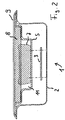
- a housing 1 can be provided which has a lower part 2 and a cover 9.
- the lower part 2 surrounds an inner space of the housing 1 on all sides except the upper side.
- the lower part 2 is configured substantially cuboid, but has rounded corners and forms an upper edge 6 for supporting a trough-shaped insert part 5.
- the lower part 2 is z. B. made of metal (and may optionally be connected to the ground potential of the motor vehicle), so that it attenuates electromagnetic waves that pass through the lower part 2, and / or so that electromagnetic waves can not pass through the lower part 2. In both cases, a shielding effect is achieved.
- the trough-shaped insert 5 defines, inside the housing 1, a partial interior space 11 which is large enough to be arranged in each case a mobile telephone, wherein the mobile telephone can be selected from a large number of different types, wherein the external dimensions of the mobile phones in a wide Range can vary.
- the in Fig. 1 From right to left extending length of the cellphone 7 shown there fills the partial interior 11 is not. In particular, there would still be room for one above (ie in the Fig. 1 pointing to the right) on the mobile phone 7 or other mobile phone protruding antenna. But also in Fig. 2 From right to left extending width of the mobile phone does not fill the part of the interior space 11.
- the support surface of the insert 5, on which the mobile phone rests 7, is preferably formed of non-slip material, preferably by a layer of soft plastic.
- the insert 5 forms both in the longitudinal section according to Fig. 1 as well as in the cross section according to Fig. 2 considers a shoulder, ie a region located laterally of the partial interior 11, in which it extends above the level of the support surface for the mobile telephone 7 in an approximately horizontal direction. From this level, the material of the insert 5 then rises to the level of the edge 6 of the lower part 2. At the said intermediate level is in the in Fig. 1 and Fig. 2 illustrated closed state of the housing 1 a foam plate 8 is placed, which may be secured to the underside of the lid 9. The height or thickness of the foam plate 8 is dimensioned such that it extends from the lower surface of the lid 9 to the intermediate level and rests there on the shoulder of the insert 5.
- the height of the insert 5 in the area of the sub-interior 11 in which the mobile phone 7 or other mobile phones can be arranged is such that the thickness of mobile phones having a thickness in the usual range (the thickness is the dimension, the in Fig. 1 and Fig. 2 extends in the vertical direction) is greater than the height between the support surface for the mobile phone 7 to the top of the shoulder.
- the mobile phone protrudes beyond the level of the shoulder and therefore pushes the foam plate 8 with the lid closed 9 on the mobile phone, as from Fig. 1 and Fig. 2 is recognizable. Therefore, the foam of the foam sheet 8 is compressed (not in Fig. 1 and Fig. 2 shown) and exerts due to the resulting elastic deformation of a pressing force on the mobile phone 7, which presses the mobile phone in addition to its weight on the support surface of the insert 5.
- the foam sheet 8 is made of a material that passes through passing electromagnetic Waves, especially in the frequency ranges used by mobile phones, causes high dielectric losses, so that the waves are attenuated and a shielding effect is achieved.
- carbon is distributed in the foam material which causes at least the substantial portion of the dielectric losses.
- the foam material may be polyurethane foam, for example.
- the electromagnetic shield formed by the housing and by the elastic material serves not only to attenuate the radio signals emanating from the mobile phone but also interfering signals that might otherwise act on the mobile phone.
- Such interference can z. B. also be generated by the motor vehicle itself or by facilities within the motor vehicle.
- C-RAM MT the homogeneous damping foam offered by Emc GmbH
- C-RAM SFC the homogeneous damping foam offered by Emc GmbH
- This absorber also damps electromagnetic waves.
- the pyramid absorber has the advantage that it can protrude much further from the bottom of the lid 9 or other lid in the part-interior in which the mobile phone is included or should be recorded.
- the pyramid tips can extend into the possibly remaining free area between the mobile phone and the edges of the tray formed by the insert and effectively prevent any movement of the mobile phone. Since the pyramid tips can be pressed with less force in the direction of the underside of the lid, the lid is still well on the lower part of the housing.
- a pyramid absorber can also be used in other embodiments of a housing.
- the lid also z. B. can be hinged to the lower part 2 via a hinge.
- a circuit board 3 is arranged in the space between the bottom of the lower part 2 and the part-inner space 11 (trough), in which the mobile phone 7 is arranged. Electrical components and circuit elements as well as other devices may be formed on the circuit board 3. Instead of a circuit board may also be provided another body carrying such devices. In particular, these devices can perform functions that serve for the operation of the mobile phone 7 or another mobile phone in the housing 1 or in another housing. In particular, it is preferred that the mobile phone can be used within the housing.
- one of the devices on the board 3 or the other body is formed as an antenna structure, so that between the antenna structure and the antenna of the mobile phone radio signals can be transmitted.
- the board 3, the antenna structure according to Fig. 7 and 8th be.
- the antenna structure is in turn connected via a passage 4 through the housing to the vehicle antenna.
- Other devices such as a compensator, and / or a second antenna structure for a Bluetooth interface between the mobile phone and the devices on the board 3 or the other body may also be provided.
- the mobile phone via the Bluetooth interface, the mobile phone can therefore be connected in a conventional manner to a hands-free device of the motor vehicle with at least one speaker and with at least one microphone.
- the housing only a single antenna structure, which may be configured broadband (ie receive broadband signals within a frequency range of the mobile phone and / or can send to the mobile phone), z. B. the antenna structure described with reference to another figure.
- the antenna structure may have a single or a plurality of individual antennas.
- the broadband frequency range includes z. B. both the signal frequency ranges in which the signals of a mobile phone network are transmitted (in particular between mobile phone and stationary base station of the network) and also in which signals for controlling the mobile phone operation and / or for coupling the mobile phone to a speakerphone in the motor vehicle transmitted (eg according to the Bluetooth standard).
- FIG. 3 shows the lower part of a housing which is configured electromagnetic shielding.
- the housing has a hard, made of substantially inelastic material lower shell, which is formed for example of plastic.
- the lower shell has a trough-shaped receiving space 23 for receiving a mobile telephone 7.
- a lining made of elastic material is inserted, for example made of TPE.
- the lining follows the contours of the lower shell and thus defines the surface of the receiving space 23.
- the material of the lining defines the bottom 24 and the self-contained circumferential lateral edge surface 25, the trough-shaped receiving space 23 down and laterally limit.
- the height of the edge surface is preferably constant over its course and large enough that mobile phones with standard dimensions do not have the Top edge of the trough-shaped receiving space 23 protrude when they are arranged therein.
- the lower shell and / or the lining are formed of electromagnetic shielding material.
- the lining may be made of a foam material which preferably has electromagnetic shielding properties.
- the lining is shaped so that its material at the edge surface 25 has a plurality of triangular projections 26 a to 26 m.
- the projections 26 are therefore also formed of elastic material.
- the projections 26 are distributed over the circumference of the receiving space 23, but preferably not evenly distributed, that is, adjacent projections have viewed along the course of the edge surface 25 at a constant distance from each other.
- the projections are each arranged on a rectilinear section A - I of the edge surface 25.
- the rectilinear sections A - I each extend angled to their two adjacent sections, so that a total of nine corners between the sections A - I are formed. Of these, eight of the nine corners are outside corners.
- One of the corners, namely the corner between the sections H and I is an inner corner, that is to say the angle between the course of the sections H and I measured within the receiving space is more than 180 °.
- the sections H and I therefore form a concave course of the edge surface 25.
- the concave course merges into a single convex course of the edge surface 25.
- the course of the edge surface is formed by a single concave portion and a single convex portion.
- sections A, B, C and D are along a spiral line. This follows because the outside corner between sections A and B and the outside corner between sections B and C have about the same corner angle, with sections A and B being about the same length but section C being longer. Again, section D following section C is approximately the same length as section C, but the angle of the corner between sections C, D is greater than the angle between sections B and C.
- the sections E, F and G also run along a spiral-shaped line, but not the same spiral-shaped line as the sections A - D.
- the entire course of the edge surface 25 therefore becomes approximately along a respective spiral-shaped line through a concave section and two partial sections educated.
- a plurality of different positions result, in which mobile phones can be arranged in the receiving space 23, wherein they rest in the respective position on the floor 24 and at the same time bear against the edge area 25 on opposite sides.
- these positions which can also be referred to as holding positions, because the mobile phone can be held in this position, the respective mobile phone is even contacted on multiple sides of points or portions of the edge surface 25.
- the lining consists of elastic material, so that on the one hand, a clamping action can arise due to elastic forces and on the other hand, mobile phones with slightly different dimensions can be kept in the same position.
- FIG. 3 also shows, in addition to the trough-shaped receiving space 23 for receiving a mobile phone and a smaller trough-shaped receiving space 31 for receiving, for example, of plugs or adapters for connecting the mobile phone formed both in the lower shell and in the lining.
- FIG. 3 shows the outlines of three different mobile phones 7a, 7b, 7c with different outer dimensions.
- the mobile phone 7b is longer than the mobile phones 7a and 7c.
- the mobile phone 7c (for example, a PDA) is wider than the mobile phones 7a and 7b.
- the section f of the edge surface 25 has a recess 32.
- this recess 32 may be arranged electrical contacts for electrically connecting the recorded in the receiving space 23 of the mobile phone 7, for example, a USB-A socket to which a charging plug for charging the battery of the mobile phone 7 can be inserted.
- electrical contacts for other purposes and / or electrical contacts may be provided for different purposes.
- such contacts may serve to connect the mobile phone to the port for transmitting the antenna signal to the vehicle antenna.
- parts of an electrical circuit can be arranged, for example a printed circuit board with corresponding components.
- the printed circuit board may, for example, have an antenna structure with which electromagnetic waves can be transmitted wirelessly between the mobile telephone 7 and the printed circuit board.
- the antenna structure may be a transmitting and / or receiving structure.
- end of the housing may be hinged in a particular embodiment of a hinge, a lid, which can be brought by turning about an axis of rotation of the hinge in a closed position of the housing.
- a foam material arranged on the underside of the lid presses on the mobile telephone arranged in the trough-shaped receiving space 23, so that this is additionally fixed in the receiving space 23.
- the foam material is preferably designed to absorb electromagnetic waves in the GHz range.
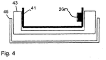
- Fig. 4 shows the cross section along the line xx in Fig. 3
- the representation is to be understood schematically and not to scale.
- the representation is explosive, ie, the three parts shown 41, 43, 45 are shown in the vertical direction at a distance from each other. In the operating state, however, the three parts abut each other.
- the housing is in Fig. 4 designated by the reference numeral 45. It is preferably made of metal (in particular sheet metal) and has in practical embodiments (as in Fig. 3 shown) preferably rounded corners. Accordingly, rounded portions are preferably also provided in the parts 41, 43, which in Fig. 4 are not shown.
- the lower shell is designated by the reference numeral 43. Unlike in Fig. 4 shown, its width corresponds to the width of the interior of the housing 45 so that it fits into the housing 45 without play.
- the lower shell is a dimensionally stable part.
- the one of the (by the lines in Fig. 4 shown) outlined space of the lower shell may be completely or partially filled with the material of the lower shell.
- the lining is designated by the reference numeral 45. It consists of TPE. On the lining, the projections 26 are formed. The projection 26m can be seen on the right in the illustration. The lining also fits without play (unlike in Fig. 4 shown) in the lower shell 43rd
- FIG. 5 shows parts of a side view of a car for operation on roads, wherein an arrangement for coupling a mobile phone to devices of the motor vehicle is shown schematically and enlarged within an oval outline.
- the car 51 has an external antenna 52, via which in particular signals for operating a mobile telephone in a mobile radio network can be transmitted and / or received.
- the antenna may also be used for transmitting and / or receiving other signals, for example for receiving signals for determining the current position of the motor vehicle in a satellite-based positioning system such as the GPS.
- different antennas may also be provided for the various signals.
- the antenna 52 is connected via an antenna line 53 to a device 54 installed in the vehicle.
- the antenna may also be directly connected to an antenna structure inside the vehicle, so the device 54 may be omitted.
- the device 54 is a unit of a hands-free system to allow people in the vehicle to make phone calls without having to hold the mobile phone in their hands.
- the device 54 is therefore connected via at least one electrical connection to at least one loudspeaker 55 and to a microphone 56.
- the received voice signals are converted via the speaker 55 into acoustic signals that may be heard in the vehicle interior, and are received in the vehicle interior via the microphone 56 sounds, so that transmit corresponding signals to other participants in the mobile network can be.
- the device 54 can directly assume the function of the mobile telephone or can forward the signals received by the microphone 56 to the mobile telephone or forward signals received from the mobile telephone to the loudspeaker 55. In this case, a processing of the signals can take place.
- z. B a built-in motor vehicle stereo.
- the edge of the vehicle interior is indicated, in which people can be while driving.
- the device 54 is therefore located outside the space intended for persons, since it is shown to the right of the line 57.
- the speaker 55, the microphone 56 and a holder 58 for holding a mobile phone are shown to the left of the line 57 and are located in the interior for persons, which is designated by the reference numeral 59.
- the space for the device 54 and other devices is typically located between the operator's control panels and the engine compartment of the vehicle and is in FIG. 5 designated by the reference numeral 60.
- a mobile phone 61 having a mobile phone antenna 62 may be received by and held by the holder 58, as indicated by two right-pointing arrows.
- the antenna structure 63 is arranged for coupling the mobile telephone antenna 62 to devices of the motor vehicle, in particular to the device 54.
- the antenna structure 63 is connected to the wall of the passenger compartment 59 via fastening elements 64a, 64b.
- the wall is in the representation of FIG. 5 symbolized by the line 57.
- the holder 58 is connected to the wall via fastening elements 65a, 65b.
- the antenna structure 63 may, for. B. based on FIG. 7 will be described, a flat, substantially two-dimensional structure whose surface normal extends approximately perpendicular through the wall and at a small distance between the antenna structure 63 and mobile telephone antenna 62 to the mobile phone antenna 62.
- the distance is z. B. smaller than 10 cm, preferably smaller than 5 cm.
- the mobile telephone antenna 62 is located in particular in the near field of the antenna structure 63 with respect to the highest limit frequency of the antenna structure 63, which is in particular equal to the highest frequency of the frequency ranges in which the antenna structure receives signals from the mobile telephone 61 or transmits them to it.
- the antenna structure 63 is expediently arranged at a location on the wall of the person room 59, at which the wall has no or at most a low shielding effect for electromagnetic radiation.
- the wall can be made of the plastic materials commonly used today in cars.
- an additional control unit 66 for operating the device 54 and / or for operating the mobile telephone 61 may be located in the passenger compartment 59.
- the control panel 66 z. B. a subscriber connection over the mobile network and / or terminated.
- the control unit 66 may also have a display device for optically displaying information, for example a display for displaying the telephone number of a calling subscriber and / or for displaying other information.
- z. B. stored in the device 54 or in the mobile phone 61 address and / or telephone number information on the control panel 66 and / or be accessed.
- the operating part 66 is as in FIG. 5 indicated, connected via a connecting line to the device 54.
- the in FIG. 5 illustrated and previously described arrangement operated, for example, as follows:
- a user sets after entering the motor vehicle 51 his mobile phone 61 in the holder 58 and turns on the mobile phone 61 a.
- the mobile phone 61 is already turned on.
- the antenna structure 63 receives signals transmitted from the mobile telephone antenna 62, which are transmitted to the device 54 via the line connection.
- the device 54 thus recognizes that a mobile phone has been coupled, passes the transmitted signals via the antenna line 53 to the outside antenna 52 and begins to establish an additional Bluetooth radio connection to the mobile telephone 61.
- the wireless connection between the antenna structure 63 and the mobile telephone antenna 62 is used for this Bluetooth connection.
- the Bluetooth connection can now be used for known applications such.
- B. the control of the mobile phone 61 by operation of the control panel 66 and / or for the connection of the mobile phone 61 to the hands-free system of the motor vehicle 51 are used.
- FIG. 6 shows an alternative arrangement in the motor vehicle 51.
- the same parts are given the same reference numerals as in FIG. 5 designated and not explained again.
- a housing 1 with a lower part 2 and a lid 9 is provided for receiving the mobile phone 61, the z. B. is arranged on a center console 96 between the front seats of a car or in the center console 96 integrated. In the case 1, it may be z. B. to act as an embodiment, as based on the FIGS. 1 to 3 has been described.
- the antenna structure 63 is arranged in the housing 1, for. B. between the trough-shaped insert part 5 and the bottom formed by the lower part 2.
- a compensator 95 is permanently installed in the vehicle, here in the vicinity of the external antenna 52.
- the compensator can, however, z. B. also be integrated into the housing 1. In the embodiment according to FIG. 5 it could be integrated in the holder 58 or in the device 54.
- an additional reflector for reducing the antenna losses due to radiation in the direction of the rear side of the antenna structure can be used, in particular when using a two-dimensional antenna structure.
- the reflector reflects the waves radiated from the antenna structure towards the rear (i.e., to the side facing away from the mobile phone) towards the front side.
- the reflector may be arranged on the carrier of the antenna structure, for. B. as an additional metallic layer as part of a board with more than two layers in which are electrically conductive areas.
- the supply line such.
- FIG. 7 represented and in a third, underlying layer of the reflector.
- the reflector can also be arranged as a separate component at a distance to the back of the antenna structure, for. B. as a metal plate, which in the embodiment of FIG. 1 and FIG. 2 between the board 3 and the bottom of the lower part 2 is arranged.
- z. B. the bottom of the housing 2 according to FIG. 1 act as a reflector.
- Antenna structures which generate circularly polarized waves or can therefore receive linearly polarized waves in any direction with high efficiency are particularly suitable for holders or housings for receiving mobile phones that allow different orientations of the mobile phone antenna.
- the holder according to FIG. 3 be combined in an advantageous manner with such an antenna structure.
- FIG. 9 Another arrangement, alternative to the in FIG. 5 and FIG. 6 shown arrangements may be provided in a motor vehicle is in FIG. 9 shown.
- the outer antenna 52 of the motor vehicle is connected via an antenna feed directly to the antenna structure 63, but in the antenna feeder other facilities such.
- the illustrated amplifier 93 may be provided for amplifying the signals.
- "direct" means that the device 54 is off FIG. 5 and FIG. 6 is not disposed in the connection between the external antenna 52 and the antenna structure 63.
- the signals received via the external antenna 52 are wirelessly transmitted from the antenna structure 63 to the mobile telephone antenna 62.
- the mobile radio network is preferably designed as WLAN.
- the mobile phone 61 is a mobile WLAN station.
- the transmission signals generated by the mobile telephone 61 are transmitted (in the reverse direction) via the said connection to the external antenna 52 and transmitted by the latter.
- the mobile telephone 61 is preferably configured to generate the required voice signals for the hands-free operation within the motor vehicle, for example according to the Bluetooth standard via the coupling to the antenna structure 63 via a line connection to a device 94, from the latter via a data bus 96 of the motor vehicle an audio device 95 and from this to a loudspeaker 55 to be transmitted.
- the audio device 95 can also be omitted if the implementation of the Bluetooth signals to control signals for driving the speaker 55 is made directly from the device 94.
- a microphone 56 is connected to the audio device 95 or directly to the device 94.
- the boundary between the vehicle interior for the stay of persons is again represented by a line 57.
- the people room is located to the left of the line 57 in the representation of FIG. 9 ,
- the incoming voice signals according to the IP standard as VoIP (Voice over Internet Protocol) signals can be transmitted.
- VoIP Voice over Internet Protocol
- the function of the mobile phone can therefore be limited to implementing the VoIP signals from the WLAN to the Bluetooth standard or another standard used for in-vehicle use.
- speech signals generated by the device 94 or by the audio device 95 can be transmitted via the antenna structure 63 to the mobile telephone 61, converted by the latter into WLAN, and transmitted via the external antenna 52.
- Fig. 7 and Fig. 8 show a preferred embodiment of an antenna structure having a plate-shaped carrier 71 and on one side (without limiting the generality: the front) in spiral waveguide executed Spiralarm Modellen.
- stripline technique is meant that on the surface of the support structure (eg a plate) strip-shaped areas extending along the surface of the support consist of electrically conductive material, while other areas of the surface of the support are not covered with electrically conductive material are.
- the wearer may wear a layer of metal on its surface that is uniformly thick and extends over the entire surface at the front.
- To produce the stripline structure can then z. B. those areas that should be free of electrically conductive material to be demetallized, z. Using corrosive materials or by grinding and polishing.
- the electrically conductive regions can also be selectively applied locally.
- the carrier 71 is made of glass fiber reinforced epoxy resin, for example, as is common in printed circuit board technology for electrical and electronic circuits.
- the carrier may be made of any other dielectric material, e.g. As ceramic or mixed with ceramic powder polytetrafluoroethylene.
- the illustrated structure has an uninterrupted region 75 formed by the electrically conductive layer.
- the electrically conductive material-free areas have the shape of two spiral arms and are designated by the reference numerals 73, 74, wherein the areas 73, 74 in the center of the spiral by a transition region 76 are interconnected ( Fig. 8 ). Accordingly, complementary regions 75a, 75b, which are part of the region 75, extend to the regions 73, 74 as far as the center of the spiral, but are electrically separated from each other by the transition region 76.
- the spiral arms 75a, 75b are therefore electrically connected to each other only over the outer region of the region 75.
- a feed region 77 made of electrically conductive material.
- the supply area 77 is again a strip. This strip runs directly opposite one of the metallic spiral arms 75a or 75b, here opposite 75a.
- the strip 77 extends to the center of the spiral, but there it traverses the region immediately opposite the transition region 76 (FIG. Fig. 8 ).
- the strip 77 in the center is electrically connected to a connection 78 which extends through the material of the carrier 71 and electrically connects the strip 77 to the center-side end of the spiral arm 75b.
- the via 78 may be omitted and the strip 77 may instead continue over extend the back of the transition region 76, continue to follow the back of the spiral arm 75b, but terminate approximately at an extent corresponding to a 180 ° bend about the center of the spiral.
- the width of the spiral arm 77 of the supply line changes in its course from the center of the spiral to the edge of the carrier 71, where he z. B. is electrically connected to the center conductors of coaxial cables 88a, 88b.
- the shield of the coaxial cable is in this case electrically connected to the electrically conductive region 75. Due to the stepwise changing width in the course of the spiral arm 77, an adaptation of the impedance to the desired connection value of the antenna structure is undertaken. For example, if a 50 ohm input is desired, but the impedance is 120 ohms without the adjustment, the stepwise change in width will result in the desired match.
- the adaptation can also be referred to as transformation of the impedance.
- the distance between the stages 79a, 79b (the distance is measured not linearly, but along the course of the spiral arm 77 along the curve) is chosen to be equal to a quarter of the wavelength of the center frequency of the frequency range , in which the antenna structure should work broadband.
- Z 2 denote the impedance which is to be transformed (without adaptation) and Z 1 the impedance to which it is to be adapted (desired connection value).
- Z T 1 Z 1 Z 2
- Z 1 3 50 ⁇ ⁇ 120 50 3 ⁇ 66 . 9 ⁇ 1
- the spiral arm of the connecting line can also become continuously wider in its course from the center of the spiral to the outside. This also allows an adjustment of the impedance can be made.
- the antenna structure has a crossover (eg 72 in Fig. 7 ), which is preferably also applied in stripline technology on the same carrier carrying the actual antennas.
- the spiral arm 77 is connected at its view from the center of the spiral outer end to a so-designed crossover.
- the crossover is used to distribute frequency signals in different frequency ranges to two different or even more than two different connection lines.
- the connecting lines are each formed by a coaxial cable 88a, 88b, for example.
- two connection lines are present and divides the crossover signals in the range of the frequency band for Bluetooth of signals in the range of a GSM frequency band.
- the crossover 72 is preferably configured as a duplexer, d. H. it not only divides frequencies onto the connection lines which correspond to frequency signals received by the antenna structure, but also makes it possible to supply transmit signals via the connection lines so that they are emitted by the antenna structure. In this case, the crossover unit combines the signals that are fed via the different connection lines of the antenna structure.
- the crossover can be used exclusively for the transmission mode.
- crossover network in stripline technology it is also possible to use commercially available, separate components which are fastened, for example, to the carrier of the antenna structure or which are fastened to another holder.
- the crossover z. B. be constructed from a suitable combination of bandpass filters.
- an amplifier is preferably provided which routes the signals on their way from the antenna structure to other devices such as an outdoor antenna of the motor vehicle or amplified to a speakerphone of the motor vehicle.
- an amplifier may be provided which transmits the transmission signals on their way reinforced to the antenna structure.
- the one or more amplifiers are z. B. part of the arrangement for transmitting the antenna signals to and / or from the mobile telephone antenna.
- the amplifier or amplifiers are mechanically connected to the holder for holding and / or receiving the mobile phone.
- the amplifier on the board 3 according to Fig. 1 be attached.
- a spiral antenna structure may also be different than with reference to FIG Fig. 7 be described and electrically connected. Examples are in the US 5,621,422 described. As explained therein, the existing two spiral arms can be electrically connected at their outer ends and are connected via a so-called 180 ° hybrid, which in turn allows the connection of connecting lines for signals in different frequency bands (as in US 5,621,422 in Fig. 9 and Fig. 10 shown and described in the associated description in columns 10 and 11).
- FIG. 10 shows a holder 101, which is configured as an electromagnetic shielding housing for receiving a mobile phone 61.
- the holder 101 has a first antenna 103 for transmitting signals of a mobile radio network (eg GSM or UMTS or WLAN) to a first mobile telephone antenna 105 or for receiving such signals.
- a second antenna 104 of the holder 101 is provided, which serves to transmit signals of a positioning system (eg GPS) to a second mobile telephone antenna 106.
- the first antenna 103 is connected via a bandpass filter 107 with a connecting line 100 of the holder 101, wherein the connecting line z. B. is a coaxial cable that connects the bracket 101 with an outdoor antenna of the motor vehicle.
- the second antenna 104 is also connected to the connecting line 100 via a further bandpass filter 108.
- the holder has a device 109 which serves to execute control, monitoring and / or diagnostic functions of devices and components installed in the vehicle.
- a device 109 which serves to execute control, monitoring and / or diagnostic functions of devices and components installed in the vehicle.
- An example has already been described and relates to the temperature monitoring of a refrigerated container of the motor vehicle.
- the device 109 is in turn connected to the connecting line 100 via a further bandpass 110.
- the holder 101 has a power supply device 112, the z. B. has a rechargeable battery with associated charging electronics and connections for components to be supplied and facilities of the holder 101.
- This power supply device 112 is also connected to the connecting line 100 via a low-pass filter 113.
- the center conductor of the cable with the bandpass filters 107, 108 and 110 and with the low-pass filter 113 is connected.
- the mobile phone 61 can receive position signals of the GPS and also receive wireless signals from a mobile radio network via the wireless connection to the first antenna 103 and send in this. Furthermore, via the connecting line 100, the power supply of facilities and components of the holder 101 can be ensured, for. B. the device 109 or any other devices that in FIG. 10 are not shown, such.
- a signal amplifier for amplifying the over the connecting line 108 to be transmitted high-frequency signals a display or illuminated controls on the bracket 101st
- the holder preferably has a device for the inductive (wireless) charging of an energy store which is part of the mobile telephone. Also, this charging device can be supplied via a power supply as described above with electrical energy for charging the mobile phone. Under an inductive charging is understood that energy is transmitted in the form of electromagnetic waves to the mobile phone and there z. B. from a coil (more generally formulated: an antenna) and introduced into the energy storage.
- the device 109 may be functionally independent of the mobile phone 61. However, it is preferred that the device 109 in the event of the occurrence of certain events, such. B. the finding that the temperature rises in the freezer container, via a further antenna, not shown, the holder 101 or the signal path a) bandpass filter 110, b) bandpass filter 107 and c) first antenna 103 transmits a signal to the mobile phone 61, which this to a reaction, eg. B. causes the transmission of signals via the mobile network.
- a reaction eg. B. causes the transmission of signals via the mobile network.
- the antennas 103, 104 are parts of a spatially distributed antenna structure of the holder 101. This shows that the antenna structure does not necessarily have to be a structural unit, even if it is preferred. In the Fig. 10 shown antenna variant was chosen because the incident during normal use of the mobile phone 61 under the open sky position signals or incident and radiated mobile signals typically propagate from the perspective of the mobile phone 61 in different solid angle ranges.
- the mobile phone antennas 105, 106 therefore have different directional characteristics from each other and are disposed in the mobile phone 61 at remote locations.
- FIG. 11 shows a variant of the arrangement of FIG. 10
- signal amplifiers 115, 116 are provided.
- a first amplifier 115 is disposed in the connection between the bandpass filter 108 and the second antenna 104. It is used to amplify position signals which pass via the connecting line 100 to the bandpass filter 108, are transmitted by the latter and are to be transmitted via the second antenna 104 to the mobile telephone 61.
- the bandpass filter 107 is off FIG. 10 replaced by a compensator 116, which also performs a signal amplification in addition to the function of bandpass filtering for the frequencies of the mobile network.
- a compensator 116 which also performs a signal amplification in addition to the function of bandpass filtering for the frequencies of the mobile network.
- both the signals received by the mobile telephone 61 via the first antenna 103 and the signals to be transmitted by the first antenna 103 to the mobile telephone 61 are amplified.
- power connections 118, 119 and 120 are shown connecting the power supply 112 to the amplifier 115, the compensator 116 and (via an auxiliary output 121 of the compensator 116) to the device 109.
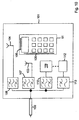
- FIG. 12 shows a holder 120 for holding a mobile phone (not shown).
- the holder 120 may again be a housing which is shielded electromagnetically to the outside.
- a single antenna 123 is provided to transmit and receive radio signals to and from the mobile telephone.
- the antenna is connected via a diplexer 125 to a first connecting line 130 for connecting the holder 121 to devices of the motor vehicle.
- these devices are a further crossover network 126, to which a first external antenna 131 for receiving position signals is connected and to which a second external antenna 132 is connected for a radio connection within a mobile radio network.
- crossover 126 via a line connection 135 another crossover 129 is connected, to which in turn a power supply device 139 of the motor vehicle is connected (low-frequency or DC voltage terminal 138 of the crossover 129) and to the z. B. via a data bus 137 (eg, CAN bus) further devices of the motor vehicle are connected, which are referred to in the example flat by the reference numeral 141.
- the devices 141 may be, for example, control, monitoring and / or diagnostic devices that serve the driving operation of the motor vehicle.
- the antenna 123 of the holder 120 is also connected via a first frequency filter 121 to a second connecting line 134 of the holder 120.
- WLAN or Bluetooth signals are transmitted to audio, video, multimedia, control and / or telematics devices of the motor vehicle via this connecting line 134.
- These include, in particular, a hands-free system, a stereo system and / or a navigation system. These devices are generally designated by the reference numeral 142.
- the antenna 123 is connected via a second frequency filter 122 to a third connecting line 136 of the holder 120. Via this connecting line 136, for example, signals in one or more different frequency bands for so-called ISM systems (Industrial Scientific Medical) of the motor vehicle are transmitted to devices which in the example are referred to by the reference symbol 143.
- ISM frequency band is a frequency range for radio frequency transmitters in industry, science and medicine that is not subject to state regulation and may be used without license. Only conditions relating to the transmission power and the interference of adjacent frequency ranges must be complied with and the devices must be expertly tested.
- the devices 143 may be, for example, control, monitoring and / or diagnostic devices that do not serve the driving of the motor vehicle but additional functions such as monitoring and control of Frachtcontainem or monitoring the driving ability of the driver.
- the device 143 is z.
- the mobile phones via the antenna 123, the crossover 125, the connecting line 130, the crossover 126 and the external antenna 132 automatically a message to a subscriber of the mobile network from.
- the mobile telephone can also be a monitoring and / or evaluation device for other ISM functions that are present in the motor vehicle.
- This has the advantage that it can operate a radio communication dependent on monitoring and / or evaluation via the mobile radio network.
- connection lines 130, 134, 136 may be z. B. act on coaxial cable.
Description
Die Erfindung betrifft eine Anordnung zur Ankopplung eines Mobiltelefons an Einrichtungen eines Kraftfahrzeugs und insbesondere zur Aufnahme des Mobiltelefons innerhalb des Kraftfahrzeugs. Die Erfindung betrifft ferner ein Verfahren zum Ankoppeln und Anordnen des Mobiltelefons in dem Kraftfahrzeug. Unter einem Mobiltelefon wird ein Gerät verstanden, das über eine Funkschnittstelle mit einer entfernt gelegenen Station kommunizieren kann, während es bewegt wird. Das Gerät muss nicht zwingend eine Tastatur aufweisen und nicht zwingend sowohl für den Sendebetrieb als auch den Empfangsbetrieb geeignet sein. Z. B. kann es sich bei dem Mobiltelefon um einen mobilen Notfallsender handeln, der auf Knopfdruck ein Notsignal zu der Station sendet.The invention relates to an arrangement for coupling a mobile phone to devices of a motor vehicle and in particular for receiving the mobile phone within the motor vehicle. The invention further relates to a method for coupling and arranging the mobile phone in the motor vehicle. A mobile telephone means a device that can communicate with a remote station via a radio interface while it is being moved. The device does not necessarily have a keyboard and is not necessarily suitable for both the transmission mode and the reception mode. For example, the mobile phone may be a mobile emergency transmitter that sends an emergency signal to the station at the push of a button.
Es sind bereits zahlreiche Halter bekannt, mit denen ein Mobiltelefon innerhalb eines Kraftfahrzeugs an einem gewünschten Ort gehalten werden kann. Meist sind in den Haltern Anschlüsse zum elektrischen Anschließen des Mobiltelefons an eine Freisprechanlage und/oder an eine Antenne des Kraftfahrzeugs integriert. Es ist jedoch auch bekannt, dass das Mobiltelefon über eine Bluetooth-Funkschnittstelle mit der in dem Kraftfahrzeug verbauten Freisprechanlage verbunden werden kann.There are already numerous holders known with which a mobile phone can be kept within a motor vehicle at a desired location. Usually in the holders connections for the electrical connection of the mobile phone to a speakerphone and / or an antenna of the motor vehicle are integrated. However, it is also known that the mobile phone can be connected via a Bluetooth radio interface with the built-in car in the car kit.
Die Halter sind jedoch in der Regel nur für eine bestimmte Bauform von Mobiltelefonen geeignet. Wenn ein anderer Typ von Mobiltelefonen gehaltert werden soll, ist in der Regel ein neuer Halter oder zumindest ein neuer Adapter erforderlich.However, the holders are usually suitable only for a particular design of mobile phones. If another type of mobile phone is to be held, a new holder or at least a new adapter is usually required.
"
Es ist eine Aufgabe der vorliegenden Erfindung, eine Anordnung anzugeben, die für die Aufnahme einer Vielzahl von unterschiedlichen Mobiltelefontypen geeignet ist. Bevorzugtermaßen soll außerdem der Innenraum des Kraftfahrzeugs gegen Funksignale abgeschirmt werden, die das Mobiltelefon aussendet. Die beigefügten Patentansprüche definieren den Schutzumfang.It is an object of the present invention to provide an arrangement suitable for accommodating a variety of different types of mobile phones. In addition, the interior of the motor vehicle should preferably be screened against radio signals that the mobile phone emits. The appended claims define the scope of protection.
Einem Aspekt der Erfindung liegt der Gedanke zugrunde, dass das Mobiltelefon drahtlos an eine Antennenstruktur des Kraftfahrzeugs angekoppelt ist. Die Antennenstruktur kann (z. B. über ein Koaxialkabel) mit einer Außenantenne des Kraftfahrzeugs verbunden sein bzw. werden. Auf diese Weise können Funksignale, die von dem Mobiltelefon ausgesendet werden von der Antennenstruktur im Innern des Kraftfahrzeugs empfangen werden, über die Verbindung zu der Außenantenne des Kraftfahrzeugs gelangen und von dieser ausgesendet werden. Dabei ist es optional außerdem möglich, dass die Signale nach ihrem Empfang von der Antennenstruktur, aber vor dem Aussenden über die Außenantenne verändert und/oder verarbeitet werden. Insbesondere können dabei den auszusendenden Informationen Zusatzinformationen hinzugefügt werden und/oder kann auf ein anderes Datenformat und/oder Übertragungsprotokoll übergegangen werden. Umgekehrt ermöglicht die Ankopplung des Mobiltelefons an die Antennenstruktur einen Empfang von Signalen, die zunächst von der Außenantenne empfangen werden, über die Verbindung zwischen der Außenantenne und der Antennenstruktur zu der Antennenstruktur übertragen werden und drahtlos von der Antennenstruktur zu der Empfangsantenne des Mobiltelefons übertragen werden, wobei die Sende-und Empfangsantenne des Mobiltelefons auch eine einzige Antenne sein kann. In entsprechender Weise, wie für Sendesignale beschrieben, kann nach dem Empfang der Empfangssignale von der Außenantenne, aber vor der Übertragung von der Antennenstruktur zu der Empfangsantenne des Mobiltelefons eine Verarbeitung und/oder Veränderung der in den Empfangssignalen enthaltenen Information durchgeführt werden.One aspect of the invention is based on the idea that the mobile phone is wirelessly coupled to an antenna structure of the motor vehicle. The antenna structure may be connected to an external antenna of the motor vehicle (eg via a coaxial cable). In this way, radio signals that are emitted by the mobile phone from the antenna structure inside the motor vehicle can be received via the connection to the outer antenna of the motor vehicle and emitted by the latter. Optionally, it is also possible for the signals to be received from the antenna structure after being received, but before being transmitted via the outside antenna be changed and / or processed. In particular, additional information can be added to the information to be transmitted and / or it is possible to proceed to a different data format and / or transmission protocol. Conversely, the coupling of the mobile telephone to the antenna structure allows reception of signals initially received by the outside antenna, transmitted to the antenna structure via the connection between the outside antenna and the antenna structure, and wirelessly transmitted from the antenna structure to the receiving antenna of the mobile telephone the transmitting and receiving antenna of the mobile phone can also be a single antenna. In a corresponding manner as described for transmission signals, after receiving the reception signals from the outside antenna but before the transmission from the antenna structure to the reception antenna of the mobile phone, processing and / or variation of the information contained in the reception signals can be performed.
Bevorzugtermaßen ist eine Einrichtung vorgesehen, die den örtlichen Bereich in dem sich das Mobiltelefon beim Betrieb über die Antennenstruktur befinden kann, beschränkt. Im Fall einer Standard-Halterung (Cradle) für ein Mobiltelefon kann eine einzige feste Position definiert sein, in der sich das Mobiltelefon befindet, wenn es von dem Halter gehalten wird. Dabei kann dieselbe Halterung dazu geeignet sein, verschiedene Mobiltelefontypen zu halten und können die Positionen, die die verschiedenen Mobiltelefontypen in der Halteposition einnehmen, von Typ zu Typ variieren.A device is preferably provided which limits the local area in which the mobile telephone can be located via the antenna structure during operation. In the case of a standard cradle for a mobile phone, a single fixed position may be defined in which the mobile phone is held when held by the holder. In this case, the same holder may be adapted to hold different types of mobile phones, and the positions occupied by the different types of mobile phones in the holding position may vary from type to type.
Gemäß der Erfindung ist es aber auch möglich, dass eine Halterung denselben Mobiltelefontyp in verschiedenen Positionen und/oder (innerhalb eines bestimmten örtlichen Bereichs) in beliebigen Positionen halten kann. Dabei ist die Antennenstruktur so relativ zu der Halterung angeordnet, dass in jeder möglichen Halteposition (dies schließt auch verschiedene Drehstellungen, d. h. Orientierungen des Mobiltelefons mit ein) zwischen der oder den Antennen des Mobiltelefons und der Antennenstruktur eine drahtlose Signalübertragung stattfinden kann.However, according to the invention, it is also possible that a holder can hold the same type of mobile phone in different positions and / or (within a certain local area) in any desired positions. In this case, the antenna structure is arranged relative to the holder such that in every possible holding position (this also includes different rotational positions, i.e. orientations of the mobile telephone) between the antenna (s) of the mobile telephone and the antenna structure, a wireless signal transmission can take place.
Dabei befindet sich die Antenne des Mobiltelefons bzw. befinden sich die Antennen des Mobiltelefons vorzugsweise im Nahfeld der Antennenstruktur und/oder befindet sich die Antennenstruktur im Nahfeld der Antenne bzw. der Antennen des Mobiltelefons. Der Abstand zwischen der Antenne bzw. den Antennen des Mobiltelefons und der Antennenstruktur beträgt daher z. B. höchstens 15 cm, insbesondere höchstens 10 cm, vorzugsweise höchstens 5 cm. Dadurch können geringe Kopplungsverluste bei der Ankopplung des Mobiltelefons an die Antennenstruktur erreicht werden.In this case, the antenna of the mobile phone or the antennas of the mobile phone are preferably in the near field of the antenna structure and / or the antenna structure is in the near field of the antenna or the antennas of the mobile phone. The distance between the antenna or the antennas of the mobile phone and the antenna structure is therefore z. B. at most 15 cm, in particular at most 10 cm, preferably at most 5 cm. This allows low coupling losses can be achieved in the coupling of the mobile phone to the antenna structure.
Unter einer Halterung für ein Mobiltelefon wird z. B. auch das im Folgenden noch beschriebene Gehäuse mit Fixierungselement verstanden. Ferner wird unter einer Halterung auch verstanden, dass die Halterung lediglich die Bewegungsmöglichkeiten des Mobiltelefons einschränkt, das Mobiltelefon aber nicht in einer unverrückbaren Position festhält. Die Halterung kann also z. B. eine mit Polstermaterial ausgekleidete Schale aufweisen, in die das Mobiltelefon hineingelegt wird und sich dann vorzugsweise im Nahfeld der Antennenstruktur befindet.Under a holder for a mobile phone z. B. also understood the housing described below with fixing element. Furthermore, a holder is also understood to mean that the holder merely restricts the possibilities of movement of the mobile telephone, but does not hold the mobile telephone in an immovable position. The holder can therefore z. B. have a lined with padding material shell, in which the mobile phone is put into it and then preferably is in the near field of the antenna structure.
Die Antennenstruktur und die Halterung können eine gemeinsame bautechnische Einheit bilden oder Teil einer gemeinsamen bautechnischen Einheit sein. Unter einer bautechnischen Einheit wird verstanden, dass die Teile der Einheit miteinander mechanisch verbunden sind und daher in einem einzigen Arbeitsvorgang in dem Kraftfahrzeug verbaut werden können.The antenna structure and the holder may form a common structural unit or be part of a common structural unit. Under a structural unit is understood that the parts of the unit are mechanically connected to each other and therefore can be installed in a single operation in the motor vehicle.
Es ist jedoch auch möglich, die Antennenstruktur und die Halterung als separate, nicht miteinander mechanisch verbundene Teile im Kraftfahrzeug zu verbauen, so dass sie erst durch den Einbau mechanisch miteinander verbunden werden. Z. B. kann die Halterung in einem vordefinierten Bereich an der zum Innenraum des Kraftfahrzeugs weisenden Oberfläche einer Frontseite des Innenraums verbaut werden. Dabei kann z. B. zwischen verschiedenen Halterungen gewählt werden, die jeweils für einen oder mehrere bestimmte Mobiltelefontypen konzipiert sind. Die Antennenstruktur aber kann an einer gegenüberliegenden Seite der Oberfläche (d. h. der Wand) des Fahrzeug-Innenraums verbaut sein und unabhängig davon, welche Halterung im Fahrzeug-Innenraum angeordnet wird, zur Kopplung mit der oder den Antennen des Mobiltelefons vorgesehen sein und im Betrieb auch funktionieren. Z. B. ist die Antennenstruktur an der Seite eines so genannten Armaturenbretts montiert, die zum Motorraum eines Straßenkraftfahrzeugs mit Frontmotor weist. Die Antennenstruktur ist daher vom Fahrzeug-Innenraum nicht sichtbar. In dem dafür vorgesehenen Bereich im Fahrzeug-Innenraum, der an derselben Stelle des Armaturenbretts liegt, an der auch die Antennenstruktur montiert ist, jedoch durch das Material des Armaturenbretts von der Antennenstruktur getrennt ist, kann dann eine geeignete Halterung für ein bestimmtes Mobiltelefon, für mehrere bestimmte Mobiltelefontypen oder ein Universalhalter für nahezu beliebige Mobiltelefontypen montiert werden. Dabei befinden sich die Antennen des Mobiltelefons und der Antennenstruktur wie oben beschrieben vorzugsweise im Nahfeld, wenn das jeweilige Mobiltelefon von der Halterung gehalten wird.However, it is also possible to obstruct the antenna structure and the holder as separate, not mechanically connected parts in the motor vehicle, so that they are mechanically connected to each other only by the installation. For example, the holder can be installed in a predefined area on the surface of a front side of the interior facing the interior of the motor vehicle. It can be z. B. be selected between different brackets, which are each designed for one or more specific types of mobile phones. However, the antenna structure may be installed on an opposite side of the surface (ie, wall) of the vehicle interior, and regardless of which bracket is disposed in the vehicle interior, be provided for coupling with the antenna or antennas of the mobile phone and also operate in operation , For example, the antenna structure is mounted on the side of a so-called instrument panel facing the engine compartment of a front-engine road vehicle. The antenna structure is therefore not visible from the vehicle interior. In the designated area in the vehicle interior, which is located at the same location of the dashboard, on which the antenna structure is mounted, but is separated by the material of the dashboard of the antenna structure, then a suitable holder for a particular mobile phone, for several certain types of mobile phones or a universal holder for almost any type of mobile phone can be mounted. In this case, as described above, the antennas of the mobile telephone and of the antenna structure are preferably in the near field when the respective mobile telephone is held by the holder.
Ein wesentlicher Vorteil dieser Vorgehensweise besteht darin, dass eine verhältnismäßig kostengünstig herzustellende Antennenstruktur fest im Kraftfahrzeug verbaut werden kann, es dem jeweiligen Inhaber des Fahrzeugs aber überlassen bleiben kann, ob und welches Mobiltelefon er an die Antennenstruktur ankoppeln möchte. Der Aufwand für die nachträgliche Montage des Halters ist verhältnismäßig gering. Insbesondere kann die Antennenstruktur bereits von vornherein mit der Außenantenne des Kraftfahrzeugs galvanisch verbunden sein, etwa über ein Koaxialkabel.A major advantage of this approach is that a relatively inexpensive to manufacture antenna structure can be permanently installed in the motor vehicle, but it can be left to the respective owner of the vehicle, whether and which mobile phone he would like to couple to the antenna structure. The cost of retrofitting the holder is relatively low. In particular, the antenna structure can already be galvanically connected to the outside antenna of the motor vehicle from the outset, for example via a coaxial cable.
Es ist in diesem Fall sogar möglich, dass die Halterung des Mobiltelefons und/oder das Mobiltelefon beim Betrieb innerhalb des Kraftfahrzeugs keinerlei galvanische Verbindung zu anderen Einrichtungen des Kraftfahrzeugs aufweisen. Die zum Betrieb des Mobiltelefons erforderliche Signalübertragung kann allein über die Antennenstruktur erfolgen, oder über eine Mehrzahl von Antennenstrukturen. Dabei können nicht nur, wie an anderer Stelle dieser Beschreibung noch näher beschrieben wird, die eigentlichen Sende- und/oder Empfangssignale des Mobiltelefons drahtlos übertragen werden, sondern auch Steuersignale und/oder Signale, die zur Ankopplung des Mobiltelefons an eine Freisprecheinrichtung des Kraftfahrzeugs übertragen werden, also z. B. Signale eines Mikrofons und/oder Lautsprechers, der bzw. die im Kraftfahrzeug verbaut sind.It is even possible in this case that the holder of the mobile phone and / or the mobile phone when operating within the motor vehicle have no galvanic connection to other devices of the motor vehicle. The signal transmission necessary for the operation of the mobile telephone can take place solely via the antenna structure, or via a plurality of antenna structures. Not only, as elsewhere in this description is described in more detail, the actual transmission and / or reception signals of the mobile phone are wirelessly transmitted, but also control signals and / or signals that are transmitted to the coupling of the mobile phone to a hands-free device of the motor vehicle, ie z. B. signals of a microphone and / or speaker, which are installed in the motor vehicle.
Aus der
Es ist eine Aufgabe eines im Folgenden beschriebenen Aspekts der Erfindung, der für sich allein realisiert werden kann oder in beliebiger Kombination mit den anderen in dieser Beschreibung beschriebenen Aspekten realisiert werden kann, eine Anordnung zur Ankopplung einer Mobiltelefonantenne an Einrichtungen eines Kraftfahrzeugs anzugeben, die Möglichkeiten, das Mobiltelefon zu nutzen, erweitern.It is an object of an aspect of the invention described in the following which can be realized on its own or can be implemented in any combination with the other aspects described in this description, an arrangement for coupling a mobile telephone antenna to devices of a motor vehicle, the possibilities to use the mobile phone, expand.
Es wird vorgeschlagen, die Antennenstruktur zum drahtlosen Übertragen von Signalen zu und/oder von der Sende- und/oder Empfangsantenne des Mobiltelefons so auszugestalten, dass die Antennenstruktur breitbandig ist. Insbesondere ist die Antennenstruktur ausgestaltet, die Signale in einem Frequenzbereich zu senden und/oder zu empfangen, der die Frequenzbänder von zumindest zwei verschiedenen Mobilfunknetzen und/oder zumindest einem Mobilfunknetz und einem weiteren Frequenzband enthält. Bei den Frequenzbändern handelt es sich also z. B. um die Frequenzbänder von zwei verschiedenen GSM-Netzen, einem GSM-Netz und einem UMTS-Netz, zwei oder mehr UMTS-Netzen oder einem Mobilfunknetz und dem Frequenzband gemäß Bluetooth-Standard.It is proposed to design the antenna structure for the wireless transmission of signals to and / or from the transmitting and / or receiving antenna of the mobile telephone in such a way that the antenna structure is broadband. In particular, the antenna structure is configured to transmit and / or receive the signals in a frequency range which contains the frequency bands of at least two different mobile radio networks and / or at least one mobile radio network and a further frequency band. The frequency bands are so z. B. the frequency bands of two different GSM networks, a GSM network and a UMTS network, two or more UMTS networks or a mobile network and the frequency band according to Bluetooth standard.
Die Antennenstruktur (bei der es sich auch um eine örtlich verteilte Antennenstruktur handeln kann) hat vorzugsweise die Eigenschaften, die im Folgenden beschrieben werden.The antenna structure (which may also be a spatially distributed antenna structure) preferably has the characteristics described below.
Bevorzugt wird, dass die Abmessungen (insbesondere die Länge und/oder Breite) von elektrisch leitfähigen Bereichen (d.h. Antennen), die die Antennenstruktur bilden, in der Größenordnung von 10 cm liegen. Dies heißt, dass bei verschiedenen Ausführungsformen der Antennenstruktur die Länge und/oder Breite z. B. bis zu 1 cm klein und/oder z. B. bis zu 1 m groß sein kann. Die Frequenzen, mit denen die Funksignale innerhalb eines Mobiltelefonnetzes übertragen werden, liegen heutzutage üblicherweise im Bereich von ca. 450 MHz (GSM, Global System for Mobile Communication, in Tansania) bis 2200 MHz (UMTS, Universal Mobile Telecommunications System). Für zukünftige Mobilfunknetze (z. B. WLAN-Netze) sind auch höhere Signalfrequenzen möglich. Die Übertragungsfrequenzen für Signale gemäß Bluetooth-Standard liegen im Bereich von 2400 bis 2500 MHz.It is preferred that the dimensions (in particular the length and / or width) of electrically conductive areas (i.e., antennas) forming the antenna structure are on the order of 10 cm. This means that in various embodiments of the antenna structure, the length and / or width z. B. up to 1 cm small and / or z. B. can be up to 1 m in size. The frequencies with which the radio signals are transmitted within a mobile telephone network are currently usually in the range of about 450 MHz (GSM, Global System for Mobile Communication, in Tanzania) to 2200 MHz (UMTS, Universal Mobile Telecommunications System). For future mobile radio networks (eg WLAN networks) higher signal frequencies are also possible. The transmission frequencies for Bluetooth standard signals are in the range of 2400 to 2500 MHz.
Die bevorzugte Ausführungsform der Antennenstruktur soll für den Empfang und/oder das Senden in mehreren, vorzugsweise in allen Frequenzbändern der genannten Systeme geeignet sein, zumindest im Frequenzbereich von 850 MHz bis 2500 MHz. Damit ist es möglich, nicht nur die Signale zum Betreiben des Mobiltelefons in einem Mobilfunknetz zu übertragen sondern außerdem noch Signale zum Betrieb in einem anderen Mobilfunknetz und/oder gemäß Bluetooth-Standard zu übertragen. Gemäß Bluetooth-Standard können zum Beispiel Steuersignale zur Steuerung des Betriebes des Mobiltelefons (z. B. Wählen einer Teilnehmernummer durch Sprachsignale oder Bedienung einer Tastatur an anderer Stelle als am Mobiltelefon) und/oder Signale im Freisprech-Betrieb übertragen werden.The preferred embodiment of the antenna structure should be suitable for receiving and / or transmitting in a plurality, preferably in all frequency bands of said systems, at least in the frequency range from 850 MHz to 2500 MHz. This makes it possible to transmit not only the signals for operating the mobile phone in a mobile network but also to transmit signals for operation in another mobile network and / or Bluetooth standard. In accordance with the Bluetooth standard, for example, control signals for controlling the operation of the mobile telephone (eg dialing a subscriber number by means of voice signals or using a keyboard at a location other than the mobile telephone) and / or signals in hands-free operation can be transmitted.
Die Antennenstruktur ist vorzugsweise so ausgestaltet, dass sie Frequenzsignale in einem Frequenzband breitbandig senden und/oder empfangen kann. Es ist auch möglich, dass die Antennenstruktur mehrere Frequenzbänder aufweist, in denen sie breitbandig senden und/oder empfangen kann, wobei die Frequenzbereiche voneinander getrennt sein können oder einander überlappen können. Jedes Frequenzband oder der gesamte Frequenzbereich werden durch eine obere Grenzfrequenz und eine untere Grenzfrequenz begrenzt. Unter breitbandig wird verstanden, dass innerhalb des Frequenzbereichs zwischen der oberen Grenzfrequenz fo und der unteren Grenzfrequenz fu der Welligkeitsfaktor s oder das Stehwellenverhältnis VSWR, das aus den Amplituden der Wellen bestimmt wird, die aus der Antennen-Versorgungsleitung hin zur Antenne laufen (Amplitude Uh) und aus der Antenne in die Antennen-Versorgungsleitung zurücklaufen (Amplitude Ur), bezogen auf eine Oktave den Faktor 2 nicht überschreitet, d.h. ![]()
![]()
![]()
![]()
Bevorzugt wird daher, dass die Antennenstruktur in diesem Sinne breitbandig für den Empfang und/oder das Senden von Signalen in den zuvor genannten Frequenzbereichen des GSM, des UMTS ein zukünftiges WLAN-Mobilfunknetz und/oder für Bluetooth ist.It is therefore preferred that the antenna structure in this sense broadband for the reception and / or transmission of signals in the aforementioned frequency ranges of the GSM, the UMTS is a future wireless network and / or Bluetooth.
Die Antennenstruktur kann eine beliebige breitbandige Antennenstruktur sein, die aus der Antennentechnik bekannt oder noch unbekannt ist. Insbesondere kann die Antennenstruktur
- selbstähnlich sein,
- selbstkomplementär sein,
- eine Form aufweisen, die bei einer Maßstabsänderung unverändert bleibt, und/oder
- mehrere Resonanzelemente aufweisen, wobei sich die Abmessungen der Resonanzelemente zueinander wie die Elemente einer geometrischen Reihe verhalten.
- be self-similar,
- be self-complementary,
- have a shape that remains unchanged upon a scale change, and / or
- have a plurality of resonance elements, wherein the dimensions of the resonance elements to each other behave like the elements of a geometric series.
Eine Antennenstruktur ist selbstähnlich, wenn sich elektrisch leitfähige und/oder nicht leitfähigen Bereiche der Antennenstruktur einander in ihrer Form (nicht aber zwingend auch in ihrer Größe) ähneln oder gleichen. Selbst ähnliche Strukturen können Fraktale sein. Fraktale sind insbesondere aus der Chaostheorie bekannt.
Z. B. weist die Antennenstruktur eine Vielzahl von verschiedenen örtlichen Gebieten auf, in denen elektrisch leitfähigen Bereiche gleicher Form wie in den anderen Gebieten angeordnet sind.An antenna structure is self-similar if electrically conductive and / or non-conductive regions of the antenna structure are similar or similar in shape (but not necessarily in size). Even similar structures can be fractals. Fractals are especially known from chaos theory.
For example, the antenna structure has a plurality of different local areas in which electrically conductive areas of the same shape as in the other areas are arranged.
Eine Antennenstruktur ist selbstkomplementär, wenn Größe und Form von elektrisch leitfähigen Bereichen der Antennenstruktur gleich der Größe und Form von elektrisch nicht leitfähigen Bereichen im örtlichen Gebiet (bei zweidimensionalen Strukturen in der Fläche) der Antennenstruktur sind. Ein Beispiel ist eine zweidimensionale Antennenstruktur, bei der von einem Zentrum der Antennenstruktur Grenzlinien zwischen elektrisch leitfähigen und nicht leitfähigen Bereichen der Struktur linear, d.h. strahlenförmig ausgehen, wobei die so gebildeten (im Bereich des Zentrums) dreieckförmigen elektrisch leitfähigen und nicht leitfähigen Bereiche gleich groß sind, also insbesondere gleich große Winkelbereiche einnehmen.An antenna structure is self-complementary if the size and shape of electrically conductive areas of the antenna structure are equal to the size and shape of electrically non-conductive areas in the local area (in two-dimensional structures in the area) of the antenna structure. An example is a two-dimensional antenna structure in which, from a center of the antenna structure, boundary lines between electrically conductive and non-conductive regions of the structure are linear, i.e., linear. emanate radiant, wherein the thus formed (in the region of the center) triangular electrically conductive and non-conductive areas are the same size, ie occupy in particular equal angular ranges.
Eine Antennenstruktur weist eine Form auf, die bei einer Maßstabsänderung unverändert bleibt, wenn für verschiedene Signalfrequenzen (für die die Antennenstruktur breitbandig ist) jeweils Strukturelemente der Antennenstruktur vorhanden sind, die normiert auf die Signalfrequenz gleich groß sind. Ein Beispiel ist eine spiralförmige Antenne. Ein nahe dem Zentrum der Spirale liegender Bereich der Antennenstruktur ist bezogen auf eine kleine Signalfrequenz genauso groß und gleich geformt wie ein weiter außen gelegener Bereich der spiralförmigen Antennenstruktur für eine größere Signalfrequenz.An antenna structure has a shape that remains unchanged in the case of a scale change if, for different signal frequencies (for which the antenna structure is broadband), structural elements of the antenna structure are present that are normalized to the signal frequency in the same way. An example is a helical antenna. A region of the antenna structure close to the center of the spiral is just as large and shaped in relation to a small signal frequency as a further outward region of the spiral antenna structure for a larger signal frequency.
Z. B. können die elektrisch leitfähigen Bereiche der Antennenstruktur sich in einer Ebene entlang einer Oberfläche eines plattenförmige Trägers erstrecken, sodass die Antennenstruktur im Wesentlichen für den Empfang und/oder das Senden von Signalen in Richtungen quer zu der Oberfläche geeignet ist. Der Träger kann z. B. eine aus der Elektrotechnik bekannte Platine sein, an deren Oberfläche mit an sich bekannten Strukturierungstechniken die gewünschten elektrisch leitfähigen Bereiche der Antennenstruktur erzeugt werden. Der elektrische Anschluss an die Antennen-Zuleitung kann dann vorteilhafter Weise auf der Rückseite der Platine bzw. des Trägers erfolgen.For example, the electrically conductive portions of the antenna structure may extend in a plane along a surface of a plate-shaped carrier, such that the antenna structure is substantially suitable for receiving and / or transmitting signals in directions transverse to the surface. The carrier may, for. Example, be known from electrical engineering board on the surface with known structuring techniques, the desired electrically conductive areas of the antenna structure are generated. The electrical connection to the antenna feed line can then be made advantageously on the back of the board or the carrier.
Ein Beispiel für den Fall, dass sich Abmessungen der Resonanzelemente (d. h. der Strukturelemente eine Antennenstruktur) zueinander wie die Elemente einer geometrischen Reihe verhalten, wird im Folgenden gegeben: Besitzt ein Resonanzelement z. B. die Länge L0, so ist das nächst kleinere t × L0 lang, das dritte t × 2L0 lang usw., wobei t auch der Stufenfaktor genannt wird: ![]()
![]()
Einer bevorzugten Ausgestaltung einer Halterung für Mobiltelefone liegt der Gedanke zugrunde, dass ein elektromagnetisch abschirmendes Gehäuse, welches beispielsweise fest im Innenraum des Kraftfahrzeugs verbaut ist, Mobiltelefone mit unterschiedlichen Außenabmessungen aufnehmen können soll, wobei die Handhabung der Vorgänge des Einbringens des Mobiltelefons in das Gehäuse und des Herausnehmens des Mobiltelefons aus dem Gehäuse für den Benutzer möglichst einfach ausgestaltet sein sollen. Dabei kann auch eine Antennenstruktur zur drahtlosen Übertragung der Signale zwischen der Mobiltelefonantenne und Einrichtungen des Fahrzeugs eingesetzt werden. Es ist jedoch auch möglich, das Mobiltelefon auf andere Weise mit den Einrichtungen zu koppeln, z. B über eine Steckverbindung an dem Mobiltelefon.A preferred embodiment of a holder for mobile phones is based on the idea that an electromagnetic shielding housing, which is installed, for example, fixed in the interior of the motor vehicle to be able to record mobile phones with different outer dimensions, the handling of the operations of introducing the mobile phone into the housing and the Take out the mobile phone from the housing for the user to be as simple as possible. In this case, an antenna structure for wireless transmission the signals are used between the mobile telephone antenna and facilities of the vehicle. However, it is also possible to couple the mobile phone in other ways with the facilities, for. B via a plug connection to the mobile phone.
Eine Öffnung, die das Gehäuse zwangsläufig zum Einbringen und Herausnehmen des Mobiltelefons haben muss, kann zumindest teilweise durch ein elastisch verformbares Element verschlossen werden. Dabei ist das elastisch verformbare Element einerseits als Fixierungselement ausgestaltet, welches das Mobiltelefon in dem geschlossenen Zustand der Öffnung bzw. in dem geschlossenen Zustand des Gehäuses mechanisch in einer momentanen Position fixiert. Andererseits ist das Fixierungselement elektromagnetisch absorbierend ausgestaltet.An opening, which must necessarily have the housing for insertion and removal of the mobile phone, can be at least partially closed by an elastically deformable element. In this case, the elastically deformable element is designed on the one hand as a fixing element, which fixes the mobile phone in the closed state of the opening or in the closed state of the housing mechanically in a current position. On the other hand, the fixing element is configured electromagnetically absorbing.
Unter elektromagnetisch absorbierend und/oder elektromagnetisch abschirmend wird in dieser Beschreibung verstanden, dass elektromagnetische Wellen, die durch das Fixierungselement bzw. durch Gehäuseteile hindurchtreten möchten, in ihrer Amplitude signifikant gedämpft werden. In besonderer Ausgestaltung ist die elektromagnetische Abschirmung speziell für ein oder mehrere der Frequenzbänder ausgelegt, in denen Mobiltelefone ihre Funksignale senden und/oder empfangen. Dabei kann es sich um die Frequenzbänder handeln, die innerhalb eines Mobiltelefonnetzes genutzt werden, und/oder um die Frequenzbänder für eine zusätzliche Funkschnittstelle, beispielsweise nach dem Bluetooth-Standard.Under electromagnetic absorbing and / or electromagnetic shielding is understood in this description that electromagnetic waves that want to pass through the fixing element or through housing parts are significantly attenuated in amplitude. In a particular embodiment, the electromagnetic shield is designed specifically for one or more of the frequency bands in which mobile phones transmit and / or receive their radio signals. These may be the frequency bands used within a mobile telephone network and / or the frequency bands for an additional radio interface, for example according to the Bluetooth standard.
Dadurch, dass ein elastisch verformbares Fixierungselement (oder auch eine Mehrzahl davon) verwendet wird, braucht das Mobiltelefon nicht an einer bestimmten, vordefinierten Position innerhalb des Gehäuses angeordnet zu werden. Vielmehr kann das Mobiltelefon in beliebiger Weise in das Gehäuse eingebracht werden und kann das Fixierungselement dazu verwendet werden, das Mobiltelefon in der beliebigen Position, die es gerade einnimmt, zu fixieren.By using an elastically deformable fixing element (or a plurality thereof), the mobile phone need not be arranged at a specific, predefined position within the housing. Rather, the mobile phone can be introduced in any manner in the housing and the fixing element can be used to fix the mobile phone in the arbitrary position that it just occupies.
Optional sind auch andere Teile des Gehäuses speziell dazu ausgestaltet, das Mobiltelefon in seiner beliebigen, momentanen Position zu fixieren, zumindest wenn auch das zumindest eine Fixierungselement an dem Mobiltelefon anliegt und dieses festhält. Zum Beispiel kann das Gehäuse ganz oder teilweise mit Materialien ausgekleidet werden, die ein Verrutschen des Mobiltelefons verhindern oder zumindest erschweren. In einer konkreten Ausgestaltung ist zumindest ein Teil des Gehäuses innen mit einem Schaumstoffmaterial versehen, auf das das Mobiltelefon aufgelegt werden kann und/oder an das das Mobiltelefon angedrückt werden kann, so dass in der fixierten Position der Schaumstoff durch das Mobiltelefon elastisch verformt wird. Die elastischen Gegenkräfte fixieren dann das Mobiltelefon oder erschweren zumindest eine Veränderung der momentanen Position des Mobiltelefons. Auch wirkt der Schaumstoff dämpfend für Stöße, die von dem Gehäuse auf das Mobiltelefon einwirken.Optionally, other parts of the housing are specially designed to fix the mobile phone in its arbitrary, instantaneous position, at least if the at least one fixing element rests on the mobile phone and this holds. For example, the housing may be completely or partially lined with materials that prevent or at least complicate slippage of the mobile phone. In a specific embodiment, at least a part of the housing is internally provided with a foam material on which the mobile phone can be placed and / or to which the mobile phone can be pressed, so that in the fixed position of the foam is elastically deformed by the mobile phone. The elastic opposing forces then fix the mobile phone or complicate at least a change in the current position of the mobile phone. Also, the foam acts to cushion shocks from the housing to the mobile phone.
Bevorzugt wird, dass auch das Fixierungselement einen Schaumstoff aufweist, in dem bevorzugt ein Stoff oder Stoffgemisch verteilt ist, der bzw. das elektromagnetisch absorbierende Eigenschaften hat.It is preferred that the fixing element also has a foam in which a substance or mixture of substances is preferably distributed which has electromagnetically absorbing properties.
Außerdem weist die Anordnung mit dem Gehäuse zumindest einen Anschluss zum Übertragen eines Antennensignals von einer Antenne des Kraftfahrzeugs zu dem Mobiltelefon und/oder umgekehrt auf. Auf diese Weise kann das Mobiltelefon über die Fahrzeugantenne betrieben werden, während es in dem Gehäuse angeordnet ist.In addition, the arrangement with the housing has at least one connection for transmitting an antenna signal from an antenna of the motor vehicle to the mobile telephone and / or vice versa. In this way, the mobile phone can be operated via the vehicle antenna while it is disposed in the housing.
Vorzugsweise sind weitere Schnittstellen zwischen dem Mobiltelefon und Einrichtungen des Kraftfahrzeugs vorhanden, z. B. eine Bluetooth-Schnittstelle, damit das Mobiltelefon z. B. an eine Freisprecheinrichtung des Kraftfahrzeuges angeschlossen werden kann.Preferably, further interfaces between the mobile phone and devices of the motor vehicle are present, for. B. a Bluetooth interface, so that the mobile phone z. B. can be connected to a speakerphone of the motor vehicle.
Der Anschluss zum Übertragen des Antennensignals ist bei einer bevorzugten Ausgestaltung über eine elektrische Leitung (z. B. ein Koaxialkabel) mit einer Antennenstruktur im Inneren des Gehäuses verbunden. Die Antennenstruktur ermöglicht es, die zwischen ihr und dem Mobiltelefon auszutauschenden Antennensignale drahtlos zu übertragen. Damit entfällt ein mechanisch-elektrischer Anschluss des Mobiltelefons an den Antennenanschluss der Anordnung. Der Benutzer braucht dann beispielsweise keinen Antennenstecker, der dem Gehäuse zugeordnet ist, mit dem Mobiltelefon zu verbinden, wenn er das Mobiltelefon in das Gehäuse einbringt.In a preferred embodiment, the connection for transmitting the antenna signal is connected via an electrical line (for example a coaxial cable) to an antenna structure in the interior of the housing. The antenna structure makes it possible to wirelessly transmit the antenna signals to be exchanged between it and the mobile telephone. This eliminates a mechanical-electrical connection of the mobile phone to the antenna terminal of the arrangement. For example, the user then does not need to connect an antenna plug associated with the housing to the mobile phone when inserting the mobile phone into the housing.
Unter einer Fixierung des Mobiltelefons in einer momentanen Position wird insbesondere verstanden, dass das Fixierungselement bei der Fixierung an dem Mobiltelefon anliegt und dabei elastisch verformt wird, so dass die Gegenkraft, die der elastischen Verformung entgegenwirkt auf das Mobiltelefon einwirkt, so dass das Mobiltelefon fixiert wird. Unter Fixierung ist jedoch nicht zwangsläufig eine starre Fixierung zu verstehen. Vielmehr kann z. B. aufgrund äußerer Kräfte trotz der Fixierung eine Bewegung des Mobiltelefons aus seiner momentanen Position heraus stattfinden. Insbesondere kann z. B. beim Bremsen des Kraftfahrzeugs das Mobiltelefon aufgrund seiner Trägheit temporär oder dauerhaft verschoben werden. Vorzugsweise ist die Verschiebung jedoch nur temporär und durch das Fixierungselement und/oder durch andere elastische Komponenten der Anordnung abgefedert.A fixation of the mobile telephone in a current position is understood to mean, in particular, that the fixing element rests against the mobile telephone during fixation and is elastically deformed, so that the opposing force counteracting the elastic deformation acts on the mobile telephone so that the mobile telephone is fixed , Fixation, however, does not necessarily mean a rigid fixation. Rather, z. B. take place due to external forces despite the fixation movement of the mobile phone from its current position out. In particular, z. B. when braking the motor vehicle, the mobile phone are temporarily or permanently moved due to its inertia. Preferably, however, the displacement is only temporary and cushioned by the fixing element and / or by other elastic components of the arrangement.
Gemäß einem weiteren Aspekt, der in dieser Beschreibung beschrieben werden soll, weist eine Anordnung eine Halterung zum Halten des Mobiltelefons in einer momentanen Position auf. Dabei kann die Halterung Teil eines Gehäuses sein, in dem das Mobiltelefon gehalten werden soll oder kann auch außerhalb eines Gehäuses angeordnet sein. Es kann eine Ankopplung der Mobiltelefonantenne an Einrichtungen eines Kraftfahrzeugs vorgesehen sein.In another aspect to be described in this specification, an arrangement includes a holder for holding the mobile phone in a current position. In this case, the holder may be part of a housing in which the mobile phone is to be held or may also be arranged outside of a housing. A coupling of the mobile telephone antenna to devices of a motor vehicle may be provided.
Unter "Halten" kann auch ein Beitrag zur Fixierung des Mobiltelefons in einer momentanen Position verstanden werden. Insgesamt kann das Mobiltelefon beispielsweise dadurch fixiert werden, dass es von der Halterung gehalten und zusätzlich von dem oben beschriebenen Fixierungselement fixiert wird."Hold" can also be understood as a contribution to the fixation of the mobile phone in a current position. Overall, the mobile phone can be fixed, for example, by being held by the holder and additionally fixed by the fixing element described above.
Vorzugsweise ist die Halterung ausgestaltet, das Mobiltelefon formschlüssig und/oder kraftschlüssig zu halten. Insbesondere kann die Halterung ausgestaltet sein, alternativ ein anderes Mobiltelefon mit anderen Außenabmessungen formschlüssig und/oder kraftschlüssig zu halten. Z. B. kann durch die Ausgestaltung der Halterung eine Mehrzahl von unterschiedlichen Positionen definiert sein, in denen jeweils eines von mehreren Mobiltelefonen mit unterschiedlichen Außenabmessungen formschlüssig und/oder kraftschlüssig von der Halterung gehalten wird. Dabei ist es bei einer konkreten Ausgestaltung der Halterung lediglich möglich, eines der mehreren Mobiltelefone mit unterschiedlichen Außenabmessungen zu halten.Preferably, the holder is designed to hold the mobile form-fitting and / or non-positively. In particular, the holder may be configured to alternatively hold another mobile phone with other external dimensions positively and / or non-positively. For example, can be defined by the configuration of the holder, a plurality of different positions, in each of which one of a plurality of mobile phones with different outer dimensions is positively and / or non-positively held by the holder. It is only possible in a specific embodiment of the holder to hold one of the several mobile phones with different outer dimensions.
Der Begriff "unterschiedliche Positionen" schließt auch den Fall mit ein, dass im Vergleich einer ersten Position mit einer zweiten Position lediglich die Ausrichtung der jeweils gehaltenen Mobiltelefone unterscheidet.The term "different positions" also includes the case that, when comparing a first position with a second position, only the orientation of the respectively held mobile phones is different.
Auf diese Weise können z. B. unterschiedliche Mobiltelefone wahlweise in ein Gehäuse eingebracht werden und über den Anschluss zum Übertragen des Antennensignals an die Antenne des Kraftfahrzeugs angeschlossen werden, zum Beispiel ein PDA (Personal Digital Assistent) und wahlweise ein Standard-Mobiltelefon mit kleinen Außenabmessungen.In this way, for. B. different mobile phones are optionally introduced into a housing and connected via the connection for transmitting the antenna signal to the antenna of the motor vehicle, for example a PDA (Personal Digital Assistant) and optionally a standard mobile phone with small outer dimensions.
Ein Benutzer kann daher jeweils eine der unterschiedlichen Positionen auswählen, die für das zu haltende Mobiltelefon besonders gut geeignet ist. Versuche habe gezeigt, dass Benutzer sehr schnell lernen, welche Position für ein bestimmtes Mobiltelefon am besten geeignet ist und sich auch gut an diese Position erinnern können.A user can therefore select one of the different positions, which is particularly well suited for the mobile phone to be held. Attempts have shown that users learn very quickly which position is best suited for a particular mobile phone and can also remember this position well.
Gemäß Anspruch 1 weist die Halterung einen wannenförmigen Aufnahmeraum zur Aufnahme des Mobiltelefons auf, der von einem Boden und einer in sich geschlossen umlaufenden seitlichen Randfläche begrenzt ist. Ein solcher wannenförmiger Aufnahmeraum kann auf unterschiedliche Weise so gestaltet sein, dass er die unterschiedlichen Positionen für Mobiltelefone mit unterschiedlichen Abmessungen bereitstellt.According to claim 1, the holder on a trough-shaped receiving space for receiving the mobile phone, which is bounded by a bottom and a self-contained circumferential peripheral edge surface. Such a trough-shaped receiving space can be designed in different ways so that it provides the different positions for mobile phones with different dimensions.
Insbesondere kann die Randfläche eine Mehrzahl von Vorsprüngen aufweisen, die zum Beispiel von einem elastischen Material gebildet werden. Diese Vorsprünge allein ermöglichen eine Mehrzahl der unterschiedlichen Positionen. Beispielsweise kann ein Mobiltelefon so in den wannenförmigen Aufnahmeraum eingebracht werden, dass es entweder auf der einen oder anderen Seite eines der Vorsprünge anliegt und/oder zwischen beliebigen Paaren der Vorsprünge oder zwischen beliebigen Kombinationen der Vorsprünge angeordnet ist und zumindest von diesen Vorsprüngen gehalten wird, dass heißt an diesen Vorsprüngen anliegt.In particular, the edge surface may have a plurality of projections, which are formed for example by an elastic material. These projections alone allow a plurality of different positions. For example, a mobile phone may be inserted into the trough-shaped receiving space so that it either rests on one or the other side of one of the projections and / or is arranged between any pairs of the projections or between any combinations of the projections and at least held by these projections means rests on these projections.
Alternativ oder zusätzlich kann die Randfläche eine oder mehrere Aussparungen und/oder Vertiefungen aufweisen.Alternatively or additionally, the edge surface may have one or more recesses and / or depressions.
Unter einem Vorsprung, einer Vertiefung und einer Aussparung wird jeweils ein Bereich (entweder ein Materialbereich oder ein materialfreier Bereich) verstanden, der einen kontinuierlichen Verlauf der Randfläche unterbricht. Bei dem kontinuierlichen Verlauf der Randfläche kann es sich um einen geradlinigen Verlauf oder um einen kontinuierlichen gekrümmten Verlauf handeln. Unter "Verlauf" ist insbesondere der Verlauf der Randfläche um den Aufnahmeraum herum zu verstehen.Under a projection, a recess and a recess is in each case an area (either a material area or a material-free area) understood that interrupts a continuous course of the edge surface. The continuous course of the edge surface may be a straight course or a continuous curved course. "Course" is to be understood in particular as the course of the edge area around the receiving space.
Vorzugsweise wird die Randfläche und/oder der Boden von einem elastischen Material gebildet. Gut geeignet ist insbesondere ein thermoplastisches Elastomer (TPE). Bei dem Material, das den Boden und die Randfläche und optional auch die Vorsprünge bildet, kann es sich um ein einziges Stück Material handeln, das beispielsweise als Formstück unter Verwendung einer Negativform hergestellt wurde.Preferably, the edge surface and / or the bottom is formed by an elastic material. Especially suitable is a thermoplastic elastomer (TPE). The material that forms the bottom and the edge surface, and optionally also the projections, may be a single piece of material, for example, made as a molded piece using a female mold.
Bei einer bevorzugten Ausführungsform weist die Randfläche entlang ihrem Verlauf um den Aufnahmeraum zumindest einen konkaven Abschnitt und einen konvexen Abschnitt auf. Unter einem konvexen Abschnitt wird ein Abschnitt verstanden, an dem der Aufnahmeraum nach außen gewölbt ist, während an einem konkaven Abschnitt der Aufnahmeraum nach innen "verkleinert" ist im Vergleich zu dem Fall, dass die Randfläche in dem Abschnitt durchgehend gerade verläuft.In a preferred embodiment, the edge surface along its course around the receiving space at least a concave portion and a convex portion. A convex portion is understood to mean a portion where the receiving space is curved outward, while at a concave portion, the receiving space is "downsized" inwardly as compared to the case where the edge area in the portion is straight.
Unter einer Wölbung wird jedoch auch verstanden, dass der Abschnitt der Randfläche einen oder mehrere Ecken aufweist, an der bzw. an denen die Randfläche entlang ihrem Verlauf um den Aufnahmeraum herum abknickt. Einem konvexen Abschnitt entspricht beispielsweise ein Verlauf mit einer Außenecke, bei der der im Aufnahmeraum gemessene Innenwinkel der Ecke zwischen 0 und 180° liegt. Einem konkaven Abschnitt entspricht beispielsweise eine Innenecke, an der der im Aufnahmeraum gemessene Innenwinkel größer als 180° ist.However, a curvature is also understood to mean that the portion of the edge surface has one or more corners on which or on which the edge surface bends along its course around the receiving space. A convex section, for example, corresponds to a course with an outer corner, in which the inner angle of the corner measured in the receiving space is between 0 and 180 °. A concave section, for example, corresponds to an inner corner, at which the inner angle measured in the receiving space is greater than 180 °.
Der zuvor beschriebenen Ausführungsform mit zumindest einem konkaven und einem konvexen Abschnitt entspricht beispielsweise daher ein Verlauf der Randfläche um den Aufnahmeraum mit zumindest einer Innenecke, an der das Material, das die Randfläche bildet, in den Aufnahmeraum hineinragt.The above-described embodiment with at least one concave and one convex section therefore corresponds, for example, to a course of the edge surface around the receiving space with at least one inner corner on which the material forming the edge surface protrudes into the receiving space.
Vorzugsweise verläuft die Randfläche in dem zumindest einen konvexen Abschnitt entlang einer Spirallinie um einen imaginären Zentralpunkt innerhalb des Aufnahmeraums. Unter einer Spirallinie wird eine Linie verstanden, die in Bezug auf den Zentrumspunkt in ihrem Verlauf kontinuierlich ihren Radius zu dem Zentrumspunkt vergrößert und dabei gleichzeitig kontinuierlich den Drehwinkel um den Zentrumspunkt entweder vergrößert oder (Spirale im Gegenuhrzeigersinn) oder verkleinert (Spirale um Uhrzeigersinn). Unter einem Verlauf der Randfläche entlang einer Spirallinie wird jedoch auch verstanden, dass die Randfläche der Spirallinie nicht exakt folgt, sondern diese beispielsweise mehrfach schneidet. Auf ein derartiges Ausführungsbeispiel, in dem die Randfläche geradlinig verlaufende Abschnitte mit Außenecken aufweist, wird noch näher eingegangen.Preferably, the edge surface in the at least one convex portion extends along a spiral line around an imaginary central point within the receiving space. A spiral line is understood to mean a line that continuously increases its radius with respect to the center point in its course to the center point while at the same time continuously increasing or (spiraling counterclockwise) or decreasing (rotating clockwise) the rotation angle about the center point. However, a course of the edge surface along a spiral line also means that the edge surface of the spiral line does not exactly follow, but instead, for example, cuts it several times. In such an embodiment in which the edge surface has rectilinear sections with outer corners, will be discussed in more detail.
Zur Erfindung gehört ferner ein Verfahren zum Anordnen eines Mobiltelefons in einen elektromagnetisch abgeschirmten Raum innerhalb eines Kraftfahrzeugs.The invention further includes a method for placing a mobile phone in an electromagnetically shielded Space inside a motor vehicle.
Bevorzugte Ausführungsformen und weitere Merkmale, die optional zusätzlich zu den bereits genannten Merkmalen vorhanden sein können, werden nun unter Bezugnahme auf die beigefügte Zeichnung beschrieben. Die einzelnen Figuren der Zeichnung zeigen:
- Fig. 1
- einen vertikalen Längsschnitt durch ein Gehäuse mit einem darin angeordneten Mobiltelefon,
- Fig. 2
- einen vertikalen Querschnitt durch die Anordnung gemäß
Fig. 1 , - Fig. 3
- eine Ansicht von oben auf einen wannenförmigen Aufnahmeraum zur wahlweisen Aufnahme von Mobiltelefonen mit unterschiedlichen Abmessungen,
- Fig. 4
- einen Querschnitt entlang der Linie x-x in
Fig. 3 , - Fig. 5
- schematisch einen vergrößert dargestellten Bereich in einem Kraftfahrzeug mit einer Anordnung zur Ankopplung eines Mobiltelefons an Einrichtungen des Kraftfahrzeugs,
- Fig. 6
- schematisch einen vergrößert dargestellten Bereich in einem Kraftfahrzeug mit einer anderen Anordnung zur Ankopplung eines Mobiltelefons an Einrichtungen des Kraftfahrzeugs,
- Fig. 7
- eine Draufsicht auf einer Vorderseite eines Trägers, der eine Antennenstruktur trägt,
- Fig. 8
- einen Ausschnitt der in
Fig. 7 dargestellten Antennenstruktur im Zentrum der Struktur, - Fig. 9
- schematisch eine weitere Anordnung zur Ankopplung eines Mobiltelefons an Einrichtungen des Kraftfahrzeugs,
- Fig. 10
- eine erste Anordnung von Frequenzfiltern und Einrichtungen einer Halterung für ein Mobiltelefon,
- Fig. 11
- eine zweite Anordnung von Frequenzfiltern und Einrichtungen für eine Mobiltelefon-Halterung und
- Fig. 12
- eine Gesamt-Anordnung von Einrichtungen in einem Kraftfahrzeug mit einer dritten Anordnung von Filtereinrichtungen und anderen Einrichtungen einer Mobiltelefon-Halterung.
- Fig. 1
- a vertical longitudinal section through a housing with a mobile phone disposed therein,
- Fig. 2
- a vertical cross section through the arrangement according to
Fig. 1 . - Fig. 3
- a top view of a trough-shaped receiving space for selectively receiving mobile phones with different dimensions,
- Fig. 4
- a cross section along the line xx in
Fig. 3 . - Fig. 5
- 3 schematically shows an enlarged area in a motor vehicle with an arrangement for coupling a mobile telephone to devices of the motor vehicle;
- Fig. 6
- 3 schematically shows an enlarged area in a motor vehicle with another arrangement for coupling a mobile telephone to devices of the motor vehicle, FIG.
- Fig. 7
- a top view on a front side of a carrier which carries an antenna structure,
- Fig. 8
- a section of in
Fig. 7 illustrated antenna structure in the center of the structure, - Fig. 9
- 1 schematically another arrangement for coupling a mobile telephone to devices of the motor vehicle,
- Fig. 10
- a first arrangement of frequency filters and means of a holder for a mobile phone,
- Fig. 11
- a second arrangement of frequency filters and devices for a mobile phone holder and
- Fig. 12
- an overall arrangement of devices in a motor vehicle with a third arrangement of filter devices and other devices of a mobile phone holder.
Wie in den
Der wannenförmige Einsatz 5 definiert im Innern des Gehäuses 1 einen Teil-Innenraum 11, der groß genug ist, um jeweils ein Mobiltelefon darin anzuordnen, wobei das Mobiltelefon aus einer großen Anzahl von unterschiedlichen Typen ausgewählt werden kann, wobei die Außenabmessungen der Mobiltelefone in einem weiten Bereich variieren können. Insbesondere die sich in
Der Einsatz 5 bildet sowohl in dem Längsschnitt gemäß
Die Schaumstoffplatte 8 ist aus einem Material hergestellt, das bei hindurch tretenden elektromagnetischen Wellen, insbesondere in den von Mobiltelefonen benutzten Frequenzbereichen, hohe dielektrische Verluste bewirkt, so dass die Wellen gedämpft werden und eine Abschirmwirkung erzielt wird. Z. B. ist in dem Schaumstoffmaterial Kohlenstoff verteilt, der zumindest den wesentlichen Anteil der dielektrischen Verluste bewirkt. Bei dem Schaumstoffmaterial kann es sich zum Beispiel um Polyurethanschaumstoff handeln.The
Ganz grundsätzlich, losgelöst von dem Ausführungsbeispiel gemäß
Geeignete Schaumstoffe mit elektromagnetischer Abschirmwirkung werden z. B. von der Emc-Technik und Consulting GmbH, Emilienstraße 35, 70563 Stuttgart vertrieben. Für das Ausführungsbeispiel gemäß
Nicht in
In dem Zwischenraum zwischen dem Boden des Unterteils 2 und dem Teil-Innenraum 11 (Wanne), in dem das Mobiltelefon 7 angeordnet ist, ist eine Platine 3 angeordnet. Elektrische Bauteile und Schaltungselemente sowie weitere Einrichtungen können an der Platine 3 ausgebildet sein. Anstelle einer Platine kann ferner ein anderer Körper vorgesehen sein, der solche Einrichtungen trägt. Diese Einrichtungen können insbesondere Funktionen ausüben, die für den Betrieb des Mobiltelefons 7 oder eines anderen Mobiltelefons in dem Gehäuse 1 oder in einem anderen Gehäuse dienen. Insbesondere wird bevorzugt, dass das Mobiltelefon innerhalb des Gehäuses benutzt werden kann. Hierzu ist eine der Einrichtungen an der Platine 3 oder dem anderen Körper als Antennenstruktur ausgebildet, so dass zwischen der Antennenstruktur und der Antenne des Mobiltelefons Funksignale übertragen werden können. Insbesondere kann die Platine 3 die Antennenstruktur gemäß
Es kann jedoch auch nur eine einzige Antennenstruktur in dem Gehäuse angeordnet sein, die breitbandig ausgestaltet sein kann (also Signale innerhalb eines Frequenzbereichs breitbandig von dem Mobiltelefon empfangen und/oder zu dem Mobiltelefon senden kann), z. B. die noch anhand einer weiteren Figur beschriebene Antennenstruktur. Dabei kann die Antennenstruktur eine einzige oder mehrere einzelne Antennen aufweisen. Der breitbandige Frequenzbereich umfasst z. B. sowohl die Signalfrequenz-Bereiche, in denen die Signale eines Mobiltelefon-Netzes übertragen werden (insbesondere zwischen Mobiltelefon und ortsfester Basisstation des Netzes) und auch in denen Signale zur Steuerung des Mobiltelefonbetriebes und/oder zur Ankopplung des Mobiltelefons an eine Freisprecheinrichtung in dem Kraftfahrzeug übertragen werden (z. B. nach dem Bluetooth-Standard).However, it may also be arranged in the housing only a single antenna structure, which may be configured broadband (ie receive broadband signals within a frequency range of the mobile phone and / or can send to the mobile phone), z. B. the antenna structure described with reference to another figure. In this case, the antenna structure may have a single or a plurality of individual antennas. The broadband frequency range includes z. B. both the signal frequency ranges in which the signals of a mobile phone network are transmitted (in particular between mobile phone and stationary base station of the network) and also in which signals for controlling the mobile phone operation and / or for coupling the mobile phone to a speakerphone in the motor vehicle transmitted (eg according to the Bluetooth standard).
Unter einem Kompenser wird eine Schaltungsanordnung zur Kompensation von Dämpfungsverlusten verstanden, die in einer Antennenleitung entstehen, wie z. B. in
Die Auskleidung ist so geformt, dass ihr Material an der Randfläche 25 eine Mehrzahl von dreiecksförmigen Vorsprüngen 26 a bis 26 m aufweist. Die Vorsprünge 26 sind daher ebenfalls aus elastischem Material gebildet. Die Vorsprünge 26 sind über den Umfang des Aufnahmeraums 23 verteilt, allerdings vorzugsweise nicht gleichmäßig verteilt, das heißt benachbarte Vorsprünge weisen betrachtet entlang dem Verlauf der Randfläche 25 keinen konstanten Abstand zueinander auf.The lining is shaped so that its material at the
Die Vorsprünge sind jeweils an einem an sich geradlinig verlaufenden Abschnitt A - I der Randfläche 25 angeordnet. Die geradlinigen Abschnitte A - I verlaufen jeweils zu ihren beiden benachbarten Abschnitten abgewinkelt, so dass insgesamt neun Ecken zwischen den Abschnitten A - I gebildet sind. Davon sind acht der neun Ecken Außenecken. Eine der Ecken, nämlich die Ecke zwischen den Abschnitten H und I ist eine Innenecke, das heißt der innerhalb des Aufnahmeraumes gemessene Winkel zwischen dem Verlauf der Abschnitte H und I beträgt mehr als 180°. Die Abschnitte H und I bilden daher einen konkaven Verlauf der Randfläche 25. An den Abschnitten I und H geht der konkave Verlauf in einen einzigen konvexen Verlauf der Randfläche 25 über. Im Ergebnis wird der Verlauf der Randfläche durch einen einzigen konkaven Abschnitt und einen einzigen konvexen Abschnitt gebildet. Es sind jedoch auch Gestaltungen der Randfläche denkbar, die mehr als einen konkaven Abschnitt aufweisen.The projections are each arranged on a rectilinear section A - I of the
Die Abschnitte A, B, C und D verlaufen entlang einer spiralförmigen Linie. Dies folgt daraus, dass die Außenecke zwischen den Abschnitten A und B und die Außenecke zwischen den Abschnitten B und C etwa den gleichen Eckwinkel aufweisen, wobei die Abschnitte A und B etwa gleich lang sind, der Abschnitt C jedoch länger ist. Der sich an den Abschnitt C anschließende Abschnitt D ist wiederum etwa gleich lang wie der Abschnitt C, wobei jedoch der Winkel der Ecke zwischen den Abschnitten C, D größer ist als der Winkel zwischen den Abschnitten B und C.The sections A, B, C and D are along a spiral line. This follows because the outside corner between sections A and B and the outside corner between sections B and C have about the same corner angle, with sections A and B being about the same length but section C being longer. Again, section D following section C is approximately the same length as section C, but the angle of the corner between sections C, D is greater than the angle between sections B and C.
Ebenfalls entlang einer spiralförmigen Linie, jedoch nicht derselben spiralförmigen Linie wie die Abschnitte A - D, verlaufen die Abschnitte E, F und G. Der gesamte Verlauf der Randfläche 25 wird daher durch einen konkaven Abschnitt und zwei Teil-Verläufe etwa entlang jeweils einer spiralförmigen Linie gebildet.The sections E, F and G also run along a spiral-shaped line, but not the same spiral-shaped line as the sections A - D. The entire course of the
Im Ergebnis und in Kombination mit den Vorsprüngen 26 ergibt sich eine Vielzahl von unterschiedlichen Positionen, in denen Mobiltelefone in dem Aufnahmeraum 23 angeordnet werden können, wobei sie in der jeweiligen Position auf dem Boden 24 aufliegen und gleichzeitig an gegenüberliegenden Seiten an der Randfläche 25 anliegen. In manchen dieser Positionen, die auch als Haltepositionen bezeichnet werden können, weil das Mobiltelefon in dieser Position gehalten werden kann, wird das jeweilige Mobiltelefon sogar an mehreren Seiten von Punkten oder Abschnitten der Randfläche 25 kontaktiert.As a result, and in combination with the projections 26, a plurality of different positions result, in which mobile phones can be arranged in the receiving
Hinzu kommt, dass die Auskleidung aus elastischem Material besteht, so dass einerseits eine Klemmwirkung aufgrund elastischer Kräfte entstehen kann und andererseits auch Mobiltelefone mit leicht unterschiedlichen Abmessungen in derselben Position gehalten werden können.In addition, the lining consists of elastic material, so that on the one hand, a clamping action can arise due to elastic forces and on the other hand, mobile phones with slightly different dimensions can be kept in the same position.
Wie
Außerdem weist der Abschnitt f der Randfläche 25 eine Aussparung 32 auf. In dieser Aussparung 32 können elektrische Kontakte zum elektrischen Anschließen des in dem Aufnahmeraum 23 aufgenommenen Mobiltelefons 7 angeordnet sein, beispielsweise eine USB-A-Buchse, an die ein Ladestecker zum Aufladen der Batterie des Mobiltelefons 7 eingesteckt werden kann.In addition, the section f of the
Bei anderen Ausführungsformen der erfindungsgemäßen Anordnung können elektrische Kontakte für andere Zwecke und/oder elektrische Kontakte für verschiedene Zwecke vorgesehen sein. Beispielsweise können solche Kontakte den Anschluss des Mobiltelefons an den Anschluss zum Übertragen des Antennensignals zu der Fahrzeugantenne dienen.In other embodiments of the arrangement according to the invention electrical contacts for other purposes and / or electrical contacts may be provided for different purposes. For example, such contacts may serve to connect the mobile phone to the port for transmitting the antenna signal to the vehicle antenna.
Unter der Unterschale, dass heißt zwischen der Unterschale und dem Boden des Gehäuses, der beispielsweise aus Metall besteht, können Teile einer elektrischen Schaltung angeordnet sein, beispielsweise eine Leiterplatte mit entsprechenden Bauteilen. Die Leiterplatte kann beispielsweise eine Antennenstruktur aufweisen, mit der elektromagnetische Wellen zwischen dem Mobiltelefon 7 und der Leiterplatte drahtlos übertragen werden können. Bei der Antennenstruktur kann es sich um eine Sende- und/oder Empfangsstruktur handeln.Under the lower shell, that is between the lower shell and the bottom of the housing, which consists for example of metal, parts of an electrical circuit can be arranged, for example a printed circuit board with corresponding components. The printed circuit board may, for example, have an antenna structure with which electromagnetic waves can be transmitted wirelessly between the
An dem rechts in
Die Darstellung in
Das Gehäuse ist in
Die Unterschale ist mit dem Bezugszeichen 43 bezeichnet. Anders als in
Die Auskleidung ist mit dem Bezugszeichen 45 bezeichnet. Sie besteht aus TPE. An der Auskleidung sind die Vorsprünge 26 ausgebildet. Der Vorsprung 26m ist rechts in der Darstellung erkennbar. Auch die Auskleidung passt ohne Spiel (anders als in
In dem Ausführungsbeispiel gemäß
In dem Ausführungsbeispiel ist die Einrichtung 54 eine Einheit eines Freisprechsystems, um es Personen in dem Fahrzeug zu ermöglichen, Telefongespräche zu führen, ohne das Mobiltelefon in den Händen halten zu müssen. Über jeweils eine elektrische Verbindung ist die Einrichtung 54 daher mit zumindest einem Lautsprecher 55 und mit einem Mikrofon 56 verbunden. Beim Führen eines Telefonats werden die empfangenen Sprachsignale über den Lautsprecher 55 in akustische Signale umgewandelt, die im Fahrzeug-Innenraum gehört werden können, und werden Laute in dem Fahrzeug-Innenraum über das Mikrofon 56 empfangen, so dass entsprechende Signale zu anderen Teilnehmern des Mobilfunknetzes übertragen werden können. Dabei kann die Einrichtung 54 unmittelbar die Funktion des Mobiltelefons übernehmen oder kann die von dem Mikrofon 56 empfangenen Signale zu dem Mobiltelefon weiterleiten bzw. von dem Mobiltelefon empfangene Signale an den Lautsprecher 55 weiterleiten. Dabei kann auch eine Bearbeitung der Signale stattfinden. Weiterhin ist es möglich, dass außer der Einrichtung 54 auch noch weitere Einrichtungen daran beteiligt sind, z. B. eine im Kraftfahrzeug eingebaute Stereoanlage.In the embodiment, the
Durch eine breite Linie 57 ist der Rand des Fahrzeug-Innenraums angedeutet, in dem sich während der Fahrt Personen befinden können. Die Einrichtung 54 befindet sich daher außerhalb des für Personen vorgesehenen Raums, da sie rechts von der Linie 57 dargestellt ist. Der Lautsprecher 55, das Mikrofon 56 sowie ein Halter 58 zum Halten eines Mobiltelefons sind links von der Linie 57 dargestellt und befinden sich in dem Innenraum für Personen, der mit dem Bezugszeichen 59 bezeichnet ist. Der Raum für die Einrichtung 54 und weitere Geräte befindet sich typischerweise zwischen den Bedienkonsolen für den Fahrzeugführer und dem Motorraum des Fahrzeugs und ist in
Auf diese Weise kann eine verlustarme Übertragung von Signalen zwischen der Antennenstruktur 63 und der Mobiltelefonantenne 62 erzielt werden, wenn das Mobiltelefon 61 von dem Halter 58 gehalten wird. Die Antennenstruktur 63 kann wie z. B. anhand von
Außerdem kann sich im Personenraum 59 ein zusätzliches Bedienteil 66 zur Bedienung der Einrichtung 54 und/oder zur Bedienung des Mobiltelefons 61 befinden. Durch Bedienung des Bedienteils 66 kann z. B. eine Teilnehmerverbindung über das Mobilfunknetz hergestellt und/oder beendet werden. Dabei kann das Bedienteil 66 auch eine Anzeigeeinrichtung zur optischen Anzeige von Informationen aufweisen, beispielsweise ein Display zur Anzeige der Telefonnummer eines anrufenden Teilnehmers und/oder zur Anzeige von anderen Informationen. Auch können z. B. in der Einrichtung 54 oder in dem Mobiltelefon 61 gespeicherte Adress-und/oder Telefonnummerinformationen über das Bedienteil 66 abgerufen werden und/oder darauf zugegriffen werden. Das Bedienteil 66 ist wie in
In bevorzugter Ausgestaltung wird die in
Bei dieser Ausführungsform ist zur Aufnahme des Mobiltelefons 61 ein Gehäuse 1 mit einem Unterteil 2 und einem Deckel 9 vorgesehen, das z. B. auf einer Mittelkonsole 96 zwischen den Vordersitzen eines PKW bzw. in die Mittelkonsole 96 integriert angeordnet ist. Bei dem Gehäuse 1 kann es sich z. B. um eine Ausgestaltung handeln, wie anhand der
Die Antennenstruktur 63 ist in dem Gehäuse 1 angeordnet, z. B. zwischen dem wannenförmigen Einsatzteil 5 und dem durch das Unterteil 2 gebildeten Boden.The
Zum Ausgleich von Dämpfungsverlusten der Signale zwischen der Außenantenne 52 und dem Mobiltelefon 61 ist ein Kompenser 95 fest im Fahrzeug verbaut, hier in der Nähe der Außenantenne 52. Der Kompenser kann jedoch z. B. auch in das Gehäuse 1 integriert sein. Bei der Ausführungsform gemäß
Unabhängig von der konkret gewählten Ausführungsform der Halterung oder des Gehäuses kann insbesondere bei Verwendung einer zweidimensionalen Antennenstruktur ein zusätzlicher Reflektor zur Reduzierung der Antennenverluste durch Abstrahlung in Richtung der Rückseite der Antennenstruktur eingesetzt werden. Der Reflektor reflektiert die zur Rückseite (d. h. zu der dem Mobiltelefon abgewandten Seite) von der Antennenstruktur abgestrahlten Wellen in Richtung der Vorderseite.Regardless of the specific embodiment of the holder or of the housing, an additional reflector for reducing the antenna losses due to radiation in the direction of the rear side of the antenna structure can be used, in particular when using a two-dimensional antenna structure. The reflector reflects the waves radiated from the antenna structure towards the rear (i.e., to the side facing away from the mobile phone) towards the front side.
Z. B. kann der Reflektor an dem Träger der Antennenstruktur angeordnet sein, z. B. als zusätzliche metallische Schicht als Teil einer Platine mit mehr als zwei Schichten, in denen sich elektrisch leitfähige Bereiche befinden. In einer der Schichten ist z. B. die eigentliche Antennenstruktur angeordnet, in einer zweiten Schicht die Zuleitung wie z. B. in
Im Folgenden soll noch auf einen Vorteil eingegangen werden, der bei Verwendung einer Antennenstruktur besteht, die zirkular polarisierte Wellen abstrahlt. Insbesondere ist dies bei Antennenstrukturen mit spiralförmigen leitfähigen und nicht leitfähigen Bereichen der Fall, z. B. bei der Ausführungsform gemäß
Antennenstrukturen, die zirkular polarisierte Wellen erzeugen bzw. deswegen auch in beliebiger Richtung linear polarisierte Wellen mit hohem Wirkungsgrad empfangen können, eignen sich besonders für Halterungen oder Gehäuse zur Aufnahme von Mobiltelefonen, die verschiedene Orientierungen der Mobiltelefonantenne erlauben. Insbesondere kann daher die Halterung gemäß
Eine weitere Anordnung, die alternativ zu den in
Die über die Außenantenne 52 empfangenen Signale werden drahtlos von der Antennenstruktur 63 zu der Mobiltelefonantenne 62 übertragen. Dabei ist das Mobilfunknetz vorzugsweise als WLAN ausgeführt. Dementsprechend ist das Mobiltelefon 61 eine mobile WLAN-Station. Auch die von dem Mobiltelefon 61 erzeugten Sendesignale werden (in umgekehrter Richtung) über die genannte Verbindung zu der Außenantenne 52 übertragen und von dieser ausgesendet.The signals received via the
Das Mobiltelefon 61 ist vorzugsweise ausgestaltet, für den Freisprechbetrieb innerhalb des Kraftfahrzeugs die erforderlichen Sprachsignale zu erzeugen, die beispielsweise gemäß dem Bluetooth-Standard über die Ankopplung an die Antennenstruktur 63 über eine Leitungsverbindung zu einer Einrichtung 94, von dieser über einen Datenbus 96 des Kraftfahrzeuges zu einer Audioeinrichtung 95 und von dieser zu einem Lautsprecher 55 übertragen zu werden. Dabei kann die Audioeinrichtung 95 auch entfallen, wenn die Umsetzung der Bluetooth-Signale auf Steuersignale zum Ansteuern des Lautsprechers 55 unmittelbar von der Einrichtung 94 vorgenommen wird. In entsprechender Weise ist ein Mikrofon 56 an die Audioeinrichtung 95 oder direkt an die Einrichtung 94 angeschlossen. Wie auch in
Wenn das Mobilfunknetz als WLAN ausgeführt ist, können die eingehenden Sprachsignale gemäß dem IP-Standard als VoIP-Signale (Voice over Internet Protocol) übertragen werden. Im Freisprechbetrieb kann sich die Funktion des Mobiltelefons daher darauf beschränken, die VoIP-Signale vom WLAN auf den Bluetooth-Standard oder einen anderen für den fahrzeuginternen Gebrauch verwendeten Standard umzusetzen. Umgekehrt können von der Einrichtung 94 oder von der Audioeinrichtung 95 erzeugte Sprachsignale über die Antennenstruktur 63 zu dem Mobiltelefon 61 übertragen werden, von diesem auf WLAN umgesetzt werden und über die Außenantenne 52 ausgesendet werden.If the mobile network is designed as WLAN, the incoming voice signals according to the IP standard as VoIP (Voice over Internet Protocol) signals can be transmitted. In hands-free mode, the function of the mobile phone can therefore be limited to implementing the VoIP signals from the WLAN to the Bluetooth standard or another standard used for in-vehicle use. Conversely, speech signals generated by the
Der Träger 71 ist beispielsweise aus glasfaserverstärktem Epoxidharz hergestellt, wie es in der Leiterplattentechnik für elektrische und elektronische Schaltungen üblich ist. Alternativ kann der Träger jedoch auch aus jedem anderen dielektrischen Material bestehen, z. B. aus Keramik oder mit Keramikpulver vermischtem Polytetrafluorethylen.The
Die in
Auf der Rückseite des Trägers 71 erstreckt sich, wie durch einen schraffierten Spiralarm in
Alternativ dazu kann die Durchkontaktierung 78 entfallen und kann sich der Streifen 77 stattdessen weiter über die Rückseite des Übergangsbereichs 76 hinweg erstrecken, der Rückseite des Spiralarms 75b weiter folgen, jedoch etwa nach einer Erstreckung, die einer 180°-Krümmung um das Zentrum der Spirale entspricht, enden.Alternatively, the via 78 may be omitted and the
Wie aus der
Die Abschirmung des Koaxialkabels ist in diesem Fall mit dem elektrisch leitfähigen Bereich 75 elektrisch verbunden. Durch die sich stufenartig ändernde Breite in dem Verlauf des Spiralarms 77 wird eine Anpassung der Impedanz an den gewünschten Anschlusswert der Antennenstruktur vorgenommen. Ist beispielsweise ein Anschlusswert von 50 Ohm erwünscht, beträgt die Impedanz ohne die Anpassung aber 120 Ohm, führt die stufenweise Änderung der Breite zu der gewünschten Anpassung. Die Anpassung kann auch als Transformation der Impedanz bezeichnet werden. Um eine optimale Anpassung zu erzielen, wird der Abstand zwischen den Stufen 79a, 79b (der Abstand wird nicht linear, sondern entsprechend dem Verlauf des Spiralarms 77 entlang der Krümmung gemessen) so gewählt, dass er gleich einem Viertel der Wellenlänge der Mittenfrequenz des Frequenzbereichs ist, in dem die Antennenstruktur breitbandig funktionieren soll.The shield of the coaxial cable is in this case electrically connected to the electrically
Es bezeichne Z 2 die Impedanz, die transformiert werden soll (ohne Anpassung) und Z 1 die Impedanz, an die angepasst werden soll (gewünschter Anschlusswert). Bei einstufiger Transformation gilt für die Impedanz ZT des ein Viertel der Wellenlänge langen Transformationswellenleiters ![]()


![]()
Alternativ zu einer Anpassung der Impedanz durch die beschriebenen, stufenartigen Breitenänderungen kann der Spiralarm der Anschlussleitung in seinem Verlauf vom Zentrum der Spirale nach außen auch kontinuierlich breiter werden. Auch hierdurch kann eine Anpassung der Impedanz vorgenommen werden.As an alternative to an adaptation of the impedance through the described step-like width changes, the spiral arm of the connecting line can also become continuously wider in its course from the center of the spiral to the outside. This also allows an adjustment of the impedance can be made.
In bevorzugter Ausgestaltung weist die Antennenstruktur eine Frequenzweiche (z. B. 72 in
Die Frequenzweiche 72 wird vorzugsweise als Duplexweiche ausgestaltet, d. h. sie teilt nicht nur Frequenzen auf die Anschlussleitungen auf, die von der Antennenstruktur empfangenen Frequenzsignalen entsprechen, sondern ermöglicht auch über die Anschlussleitungen Sendesignale zuzuführen, damit diese von der Antennenstruktur ausgesendet werden. In diesem Fall vereint die Frequenzweiche die Signale, die über die verschiedenen Anschlussleitungen der Antennenstruktur zugeführt werden.The
Auch kann die Frequenzweiche ausschließlich für den Sendebetrieb verwendet werden.Also, the crossover can be used exclusively for the transmission mode.
Alternativ zu der beschriebenen Ausgestaltung der Frequenzweiche in Streifenleitertechnik können auch handelsübliche, separate Bauelemente verwendet werden, die beispielsweise an dem Träger der Antennenstruktur befestigt werden oder die an einer anderen Halterung befestigt werden. Dabei kann die Frequenzweiche z. B. aus einer geeigneten Kombination von Bandpassfiltern aufgebaut sein.As an alternative to the described embodiment of the crossover network in stripline technology, it is also possible to use commercially available, separate components which are fastened, for example, to the carrier of the antenna structure or which are fastened to another holder. In this case, the crossover z. B. be constructed from a suitable combination of bandpass filters.
Um Dämpfungsverluste bei der drahtlosen Übertragung der Signale zwischen der Antennenstruktur und der Mobiltelefonantenne zu kompensieren (einschließlich der Möglichkeit, eine zusätzliche Verstärkung vorzunehmen), ist vorzugsweise ein Verstärker vorgesehen, der die Signale auf ihrem Weg von der Antennenstruktur zu anderen Einrichtungen, wie beispielsweise einer Außenantenne des Kraftfahrzeugs oder zu einer Freisprecheinrichtung des Kraftfahrzeugs verstärkt. Alternativ oder zusätzlich kann ein Verstärker vorgesehen sein, der die Sendesignale auf ihrem Weg zu der Antennenstruktur verstärkt. Der oder die Verstärker sind z. B. Teil der Anordnung zur Übertragung der Antennensignale zu und/oder von der Mobiltelefonantenne. Beispielsweise sind der oder die Verstärker mechanisch mit dem Halter zum Halten und/oder Aufnehmen des Mobiltelefons verbunden. Z. B. kann der Verstärker an der Platine 3 gemäß
Eine spiralförmige Antennenstruktur kann auch anders als anhand von
Im Folgenden werden die
Ferner weist die Halterung eine Einrichtung 109 auf, die der Ausführung von Steuerungs-, Überwachungs- und/oder Diagnosefunktionen von im Fahrzeug verbauten Einrichtungen und Komponenten dient. Ein Beispiel ist bereits beschrieben worden und betrifft die Temperaturüberwachung eines Kühlcontainers des Kraftfahrzeugs. Die Einrichtung 109 ist über einen weiteren Bandpass 110 wiederum mit der Anschlussleitung 100 verbunden.Furthermore, the holder has a
Ferner weist die Halterung 101 eine Stromversorgungseinrichtung 112 auf, die z. B. eine wieder aufladbare Batterie mit zugehöriger Ladeelektronik sowie Anschlüsse für zu versorgende Komponenten und Einrichtungen der Halterung 101 aufweist. Diese Stromversorgungseinrichtung 112 ist über ein Tiefpassfilter 113 ebenfalls mit der Anschlussleitung 100 verbunden. Im Fall des Koaxialkabels ist daher z. B. der Zentrumsleiter des Kabels mit den Bandpassfiltern 107, 108 und 110 sowie mit dem Tiefpassfilter 113 verbunden.Furthermore, the
Auf diese Weise kann das Mobiltelefon 61 Positionssignale des GPS empfangen und auch über die drahtlose Verbindung zu der ersten Antenne 103 Funksignale aus einem Mobilfunknetz empfangen und in dieses senden. Ferner kann über die Anschlussleitung 100 die Stromversorgung von Einrichtungen und Komponenten der Halterung 101 gewährleistet werden, z. B. der Einrichtung 109 oder etwaiger anderer Einrichtungen, die in
Bevorzugtermaßen weist die Halterung eine Einrichtung zum induktiven (drahtlosen) Laden eines Energiespeichers auf, der Teil des Mobiltelefons ist. Auch diese Ladeeinrichtung kann über eine Stromversorgung wie zuvor beschrieben mit elektrischer Energie zum Laden des Mobiltelefons versorgt werden. Unter einem induktiven Laden wird verstanden, dass Energie in Form von elektromagnetischen Wellen zu dem Mobiltelefon übertragen wird und dort z. B. von einer Spule (allgemeiner formuliert: einer Antenne) aufgenommen und in den Energiespeicher eingebracht wird.The holder preferably has a device for the inductive (wireless) charging of an energy store which is part of the mobile telephone. Also, this charging device can be supplied via a power supply as described above with electrical energy for charging the mobile phone. Under an inductive charging is understood that energy is transmitted in the form of electromagnetic waves to the mobile phone and there z. B. from a coil (more generally formulated: an antenna) and introduced into the energy storage.
Um auf das Ausführungsbeispiel gemäß
Die Antennen 103, 104 sind Teile einer örtlich verteilten Antennenstruktur der Halterung 101. Dies zeigt, dass die Antennenstruktur nicht zwingend eine bautechnische Einheit sein muss, auch wenn sie es vorzugsweise ist. Die in
Ferner ist das Bandpassfilter 107 aus
Die Antenne 123 der Halterung 120 ist außerdem über ein erstes Frequenzfilter 121 mit einer zweiten Anschlussleitung 134 der Halterung 120 verbunden. Über diese Anschlussleitung 134 werden zum Beispiel WLAN- oder Bluetooth-Signale zu Audio-, Video-, Multimedia-, Steuer- und/oder Telematikeinrichtungen des Kraftfahrzeugs übertragen. Dazu zählen insbesondere eine Freisprechanlage, eine Stereoanlage und/oder ein Navigationssystem. Diese Einrichtungen sind pauschal mit dem Bezugszeichen 142 bezeichnet.The antenna 123 of the
Die Antenne 123 ist über ein zweites Frequenzfilter 122 mit einer dritten Anschlussleitung 136 der Halterung 120 verbunden. Über diese Anschlussleitung 136 werden zum Beispiel Signale in einem oder mehreren verschiedenen Frequenzbändern für so genannte ISM-Systeme (Industrial Scientific Medical) des Kraftfahrzeugs zu Einrichtungen übertragen, die im Beispiel pauschal mit dem Bezugszeichen 143 bezeichnet sind. Ein ISM-Frequenzband ist ein Frequenzbereich für Hochfrequenz-Sendegeräte in Industrie, Wissenschaft und Medizin, der nicht der staatlichen Regulierung unterliegt und lizenzfrei genutzt werden darf. Es müssen lediglich Auflagen bezüglich der Sendeleistung und der Störung benachbarter Frequenzbereiche eingehalten werden und die Geräte entsprechend fachkundig geprüft werden.The antenna 123 is connected via a
Bei den Einrichtungen 143 kann es sich zum Beispiel um Steuerungs-, Überwachungs- und/oder Diagnoseeinrichtungen handeln, die nicht dem Fahrbetrieb des Kraftfahrzeugs sondern Zusatzfunktionen wie Überwachung und Steuerung von Frachtcontainem oder Überwachung der Fahrtüchtigkeit des Fahrers dienen. Die Einrichtung 143 ist z. B. ein aktiver Transponder, der über eine Funkschnittstelle 145 mit einem Temperatursensor 146 in einem Kühlcontainer verbunden ist. Um die Historie der von dem Temperatursensor 146 gelieferten Temperatursignale aufzeichnen zu können, weist der Transponder 143 einen Datenspeicher 147 auf. Sobald ein Mobiltelefon von der Halterung 120 aufgenommen ist und über die Antenne 123, das Frequenzfilter 122 und die Anschlussleitung 136 an den Transponder 143 angekoppelt ist, ruft das Mobiltelefon die Historie in Form der gespeicherten Temperaturwerte ab und stellt fest, ob z. B. eine zulässige Höchsttemperatur in dem Kühlcontainer überschritten worden ist. Wenn dies der Fall ist, setzt das Mobiltelefonen über die Antenne 123, die Frequenzweiche 125, die Anschlussleitung 130, die Frequenzweiche 126 und die Außenantenne 132 automatisch eine Meldung an einen Teilnehmer des Mobilfunknetzes ab.The
In entsprechender Weise kann das Mobiltelefon eine Überwachungs- und/oder Auswertungseinrichtung auch für andere ISM-Funktionen sein, die in dem Kraftfahrzeug vorhanden sind. Dies hat den Vorteil, dass es eine von Überwachung und/oder Auswertung abhängige Funkkommunikation über das Mobilfunknetz betreiben kann.In a corresponding manner, the mobile telephone can also be a monitoring and / or evaluation device for other ISM functions that are present in the motor vehicle. This has the advantage that it can operate a radio communication dependent on monitoring and / or evaluation via the mobile radio network.
Bei den Anschlussleitungen 130, 134, 136 kann es sich z. B. um Koaxialkabel handeln.In the
Claims (7)
- Arrangement for holding a mobile telephone (7) in a motor vehicle and for coupling the mobile telephone (7) to devices in the motor vehicle, in particular to an external antenna and/or to a hands-free device in the motor vehicle, with the arrangement having an antenna structure (63) for wire-free transmission of signals to and/or from a transmitting and/or receiving antenna (62) of the mobile telephone (7),
wherein
the arrangement has a holder which at least restricts the movement capabilities of the mobile telephone (7), wherein• the holder is designed to hold the same mobile telephone type in any desired holding positions within a local area which is bounded by the holder, and is designed to hold different mobile telephone types,• the antenna structure (63) is designed and is arranged relative to the holder such that wire-free signal transmission can take place between the antenna or antennas of the held mobile telephone (7) and the antenna structure (63) in any possible holding position, and• the holder comprises a trough-shaped holding area (5) for holding the mobile telephone (7), which holding area (5) is bounded by a base as supporting surface for the mobile telephone (7) and an intrinsically closed, circumferential, side edge surface. - Arrangement according to Claim 1, with the antenna structure (63) being used both for coupling the transmitting and/or receiving antenna of a mobile telephone (7) to an external antenna (52) on the motor vehicle and for wire-free coupling of the mobile telephone (7) to a hands-free device in the motor vehicle.
- Arrangement according to one of the preceding claims, with the antenna structure being designed to emit circular-polarized waves.
- Arrangement according to one of the preceding claims, with the antenna structure having spiral electrically conductive areas (75a, 75b).
- Arrangement according to the preceding claim, with the antenna structure having a feed point (78) which is located at the centre of the spiral and is connected to the spiral areas (75a, 75b).
- Arrangement according to one of the preceding claims, with the holder having an electromagnetically screening housing (1), with an opening for introduction of the mobile telephone (7) into the housing (1) and for removal of the mobile telephone (7) from the housing (1), and with the antenna structure being arranged in the electromagnetically screening housing (1).
- Arrangement according to one of the preceding claims, with the holder having a holding area (23) for holding the mobile telephone (7), and with the antenna structure extending essentially over the entire length of an outer surface of the holding area.
Applications Claiming Priority (3)
| Application Number | Priority Date | Filing Date | Title |
|---|---|---|---|
| DE102006017661 | 2006-04-12 | ||
| DE102006034128A DE102006034128A1 (en) | 2006-04-12 | 2006-07-20 | Arrangement for receiving a mobile phone within a motor vehicle |
| PCT/EP2007/003328 WO2007118694A1 (en) | 2006-04-12 | 2007-04-05 | A device for coupling and housing a mobile telephone in a motor vehicle |
Publications (3)
| Publication Number | Publication Date |
|---|---|
| EP2011243A1 EP2011243A1 (en) | 2009-01-07 |
| EP2011243B1 EP2011243B1 (en) | 2009-08-26 |
| EP2011243B2 true EP2011243B2 (en) | 2017-03-22 |
Family
ID=38109982
Family Applications (1)
| Application Number | Title | Priority Date | Filing Date |
|---|---|---|---|
| EP07724266.7A Active EP2011243B2 (en) | 2006-04-12 | 2007-04-05 | A device for coupling and housing a mobile telephone in a motor vehicle |
Country Status (5)
| Country | Link |
|---|---|
| US (1) | US8238984B2 (en) |
| EP (1) | EP2011243B2 (en) |
| DE (2) | DE102006034128A1 (en) |
| ES (1) | ES2329734T5 (en) |
| WO (1) | WO2007118694A1 (en) |
Families Citing this family (40)
| Publication number | Priority date | Publication date | Assignee | Title |
|---|---|---|---|---|
| KR100783112B1 (en) * | 2006-07-27 | 2007-12-07 | 삼성전자주식회사 | Wireless communication device available for mobile broadcasting and bluetooth with single antenna |
| DE102007029952B4 (en) | 2007-06-28 | 2022-09-22 | Bayerische Motoren Werke Aktiengesellschaft | Information transmission device |
| DE102007039879A1 (en) * | 2007-08-20 | 2009-03-05 | Funkwerk Dabendorf Gmbh | Arrangement for coupling and receiving a mobile telephone within a motor vehicle |
| US9324230B2 (en) * | 2008-12-04 | 2016-04-26 | Gentex Corporation | System and method for configuring a wireless control system of a vehicle using induction field communication |
| DE202008004580U1 (en) | 2008-04-02 | 2008-07-03 | C&J Direct Gmbh & Co. Kg | Device for receiving a mobile terminal |
| US20090264066A1 (en) * | 2008-04-17 | 2009-10-22 | Ta-Fu Cheng | Circular polarized repeater and transmission method thereof |
| DE102009033751B4 (en) | 2009-07-17 | 2012-03-15 | Funkwerk Dabendorf Gmbh | Wireless coupling of an electronic device with radio link, in particular a mobile phone, to devices of a motor vehicle |
| US20110068974A1 (en) * | 2009-09-24 | 2011-03-24 | At&T Intellectual Property I, L.P. | Inline GPS Receiver Module |
| DE102011011053A1 (en) | 2010-02-13 | 2011-08-18 | PEIKER acustic GmbH & Co. KG, 61381 | Arrangement for coupling a mobile telephone to an external antenna |
| DE102010003888B4 (en) | 2010-04-13 | 2023-06-07 | Bayerische Motoren Werke Aktiengesellschaft | Cradle for a portable electronic device |
| DE102010019904A1 (en) | 2010-05-05 | 2011-11-10 | Funkwerk Dabendorf-Gmbh | Arrangement for wireless connection of wireless device i.e. mobile phone, to high-frequency line, has electrically conductive layer deposited on surface for receiving radio waves from coupling antenna, and strip line applied on surface |
| DE102010026698A1 (en) | 2010-07-07 | 2012-01-12 | Funkwerk Dabendorf Gmbh | Arrangement for the wireless connection of a radio |
| DE102010027620A1 (en) | 2010-07-23 | 2012-01-26 | Funkwerk Dabendorf Gmbh | Coupling of an electronic device with a radio link, in particular a mobile phone, to devices of a motor vehicle |
| DE102010054576B4 (en) | 2010-12-15 | 2019-02-07 | Volkswagen Ag | Device for coupling a mobile terminal to a vehicle |
| JP5264974B2 (en) * | 2011-02-01 | 2013-08-14 | 本田技研工業株式会社 | Non-contact power transmission device |
| JP5439416B2 (en) * | 2011-03-04 | 2014-03-12 | 株式会社東芝 | Wireless power transmission device |
| WO2012144222A1 (en) * | 2011-04-22 | 2012-10-26 | パナソニック株式会社 | Vehicle-mounting charging apparatus and vehicle mounted therewith |
| DE102011105358A1 (en) | 2011-06-22 | 2012-12-27 | Friedrich-Alexander-Universität Erlangen - Nürnberg | Mobile phone holder for accommodating mobile phone of any size in motor vehicle, has antenna structure, by which mobile phone-side antennas are coupled to supply network for motor vehicle side handsfree |
| DE102011105355B4 (en) | 2011-06-22 | 2022-09-08 | Paragon Ag | mobile phone holder for motor vehicles |
| JP2013103582A (en) * | 2011-11-14 | 2013-05-30 | Honda Motor Co Ltd | Structure for mounting power control unit on vehicle body |
| DE102011120250B4 (en) * | 2011-12-05 | 2023-05-04 | Volkswagen Aktiengesellschaft | Telephone antenna coupling board for a vehicle |
| DE102011120194A1 (en) | 2011-12-05 | 2013-06-06 | Volkswagen Aktiengesellschaft | Pocket-shaped retention device for arrangement at e.g. dashboard for retention of mobile radio telephone in passenger car, has connection sections for connecting plate-shaped portion with base plate along three edges of plate-shaped portion |
| DE102012007922A1 (en) * | 2012-04-24 | 2013-10-24 | Peiker Acustic Gmbh & Co. Kg | Integration device and method for producing a wall of a receiving device |
| DE102012010404B4 (en) | 2012-05-25 | 2018-10-31 | Audi Ag | Arrangement for receiving at least one small electronic device |
| US9520638B2 (en) | 2013-01-15 | 2016-12-13 | Fitbit, Inc. | Hybrid radio frequency / inductive loop antenna |
| DE102013207898A1 (en) | 2013-04-30 | 2014-10-30 | Novero Dabendorf Gmbh | Compensation of signal attenuation in the transmission of transmission signals of a mobile device |
| DE102013011881A1 (en) * | 2013-07-17 | 2015-01-22 | Peiker Acustic Gmbh & Co. Kg | Mobile phone integration means |
| US9698467B2 (en) | 2013-08-06 | 2017-07-04 | The Boeing Company | Wired ethernet adaptor for portable electronic devices |
| DE102013215727A1 (en) * | 2013-08-09 | 2015-02-12 | Bayerische Motoren Werke Aktiengesellschaft | Mobile device holding device for a vehicle |
| GB2517791B (en) * | 2013-09-03 | 2018-03-21 | Jaguar Land Rover Ltd | Antenna with device-shaped aperture locator for low-loss coupling |
| US9093750B2 (en) * | 2013-09-12 | 2015-07-28 | Laird Technologies, Inc. | Multiband MIMO vehicular antenna assemblies with DSRC capabilities |
| DE102013220476A1 (en) * | 2013-10-10 | 2015-04-30 | Volkswagen Aktiengesellschaft | Holding device for a mobile telephone in a vehicle |
| DE102015202254A1 (en) * | 2015-02-09 | 2016-08-11 | Volkswagen Aktiengesellschaft | Storage compartment and door, center console, armrest or the like with such a storage compartment |
| DE102015112127A1 (en) | 2015-03-17 | 2016-09-22 | Peiker Acustic Gmbh & Co. Kg | integration means |
| DE102015004722A1 (en) | 2015-04-09 | 2016-10-13 | Kathrein-Werke Kg | System for the wireless coupling of a mobile radio terminal to an external antenna structure |
| US20180065570A1 (en) * | 2016-09-07 | 2018-03-08 | Thunder Power New Energy Vehicle Development Compa ny Limited | Dynamic device housing for a transportation apparatus |
| DE102016217498B4 (en) | 2016-09-14 | 2019-03-07 | Volkswagen Aktiengesellschaft | Space-neutral coupling antenna |
| CN107426928A (en) * | 2017-05-26 | 2017-12-01 | 广东高标电子科技有限公司 | Controller for electric vehicle and electric car |
| CN108808803A (en) * | 2018-07-27 | 2018-11-13 | 舟山市普陀新伟电子设备厂 | Multi-functional mobile phone charging auxiliary device |
| US20230102508A1 (en) * | 2020-01-24 | 2023-03-30 | Jyri Kaija | Functional Housing Structure for an Electronic Device |
Family Cites Families (46)
| Publication number | Priority date | Publication date | Assignee | Title |
|---|---|---|---|---|
| JP2662567B2 (en) | 1987-09-25 | 1997-10-15 | アイシン精機株式会社 | Three-resonance microstrip antenna device |
| GB2236910B (en) | 1989-09-28 | 1993-12-08 | Technophone Ltd | A housing for electronic circuitry |
| US5336896A (en) | 1993-02-04 | 1994-08-09 | Katz Joseph M | Cellular telephone users protective device |
| WO1997017792A1 (en) | 1993-04-05 | 1997-05-15 | Crowley Robert J | Antenna transmission coupling arrangement |
| US5493702A (en) | 1993-04-05 | 1996-02-20 | Crowley; Robert J. | Antenna transmission coupling arrangement |
| DE9311242U1 (en) * | 1993-07-28 | 1993-09-16 | Votronic Entwicklung & Prod | Mobile phone for motor vehicles |
| US5621422A (en) | 1994-08-22 | 1997-04-15 | Wang-Tripp Corporation | Spiral-mode microstrip (SMM) antennas and associated methods for exciting, extracting and multiplexing the various spiral modes |
| CA2225389A1 (en) | 1995-06-23 | 1997-01-09 | Andreas Peiker | Telephone set with a handset having a mouthpiece and/or an earpiece |
| JPH10215305A (en) | 1997-01-30 | 1998-08-11 | Ando Electric Co Ltd | Measurement device for personal handy phone system |
| DE19707318C2 (en) | 1997-02-12 | 1999-12-30 | Sommer Allibert Lignotock Gmbh | Hands-free system for a mobile phone |
| DE19717834B4 (en) | 1997-04-26 | 2006-12-14 | Rohde & Schwarz Gmbh & Co. Kg | Antenna coupler for mobile phones |
| US5974333A (en) | 1997-07-25 | 1999-10-26 | E-Lead Electronic Co., Ltd. | Automobile acoustic unit having integrated cellular phone capabilities |
| US6134421A (en) | 1997-09-10 | 2000-10-17 | Qualcomm Incorporated | RF coupler for wireless telephone cradle |
| JPH11227536A (en) * | 1998-02-13 | 1999-08-24 | Nissan Motor Co Ltd | Portable telephone holder for vehicle |
| US6259407B1 (en) | 1999-02-19 | 2001-07-10 | Allen Tran | Uniplanar dual strip antenna |
| DE19921533C1 (en) | 1999-05-11 | 2001-01-04 | Mannesmann Vdo Ag | Communication system of a motor vehicle |
| US7612528B2 (en) * | 1999-06-21 | 2009-11-03 | Access Business Group International Llc | Vehicle interface |
| DE10008751A1 (en) * | 2000-02-24 | 2001-09-20 | Andreas Peiker | Arrangement for using mobile telephone in vehicle, comprises removable docking station offering hands-free operation |
| DE19953648A1 (en) | 1999-11-08 | 2001-05-10 | Lutz Rothe | Modular dual band planar coupler for external mobile phone antennas uses slot line resonators has no dielectric parts |
| US6317089B1 (en) | 1999-12-23 | 2001-11-13 | Wilson Electronics, Inc. | Hand-held transceiver antenna system |
| DE10037241A1 (en) | 2000-07-31 | 2002-02-14 | Siemens Ag | Mobile telephone holder for passenger compartment of motor vehicle, capacitively couples high frequency signals from telephone antenna to external antenna via coupling antenna |
| US7248901B2 (en) | 2001-01-18 | 2007-07-24 | Andreas Peiker | Arrangement for handling a communication device |
| DE10201612A1 (en) * | 2001-01-18 | 2002-07-25 | Andreas Peiker | Arrangement for handling communications device has holder with geometric or mechanical adaptation for device, in communication with device and containing electronic circuit |
| US7079086B2 (en) * | 2001-02-15 | 2006-07-18 | Integral Technologies, Inc. | Low cost electromagnetic field absorbing devices manufactured from conductive loaded resin-based materials |
| JP2003011734A (en) | 2001-04-26 | 2003-01-15 | Denso Corp | Mounting structure of electrical apparatus for vehicle |
| DE10123556C2 (en) | 2001-05-15 | 2003-07-03 | Parts Mobilphon & Zubehoer Gmb | Holder for easily detachable attachment of a cell phone in a motor vehicle |
| DE10129408A1 (en) | 2001-06-19 | 2003-01-02 | Rohde & Schwarz | antenna |
| US6563466B2 (en) | 2001-09-26 | 2003-05-13 | Ericsson Inc. | Multi-frequency band inverted-F antennas with coupled branches and wireless communicators incorporating same |
| DE10313498A1 (en) * | 2002-05-18 | 2003-12-04 | Audioton Kabelwerk Gmbh | Antenna coupler for mobile radiotelephone service devices sets up electromagnetic coupling of high-frequency signals via an external antenna like a car aerial |
| US20040072558A1 (en) * | 2002-10-15 | 2004-04-15 | Van Bosch James A. | System and method of forwarding an incoming call to a vehicle's embedded transceiver |
| US6928281B2 (en) | 2002-12-12 | 2005-08-09 | Visteon Global Technologies, Inc. | Active antenna system with fault detection |
| WO2004086558A1 (en) * | 2003-03-25 | 2004-10-07 | Audioton Kabelwerk Gmbh Zweigniederlassung Scheinfeld | Antenna coupler and mount for mobile radio terminals |
| DE10313625A1 (en) * | 2003-03-26 | 2004-10-07 | Siemens Ag | Receiver e.g. for portable radio equipment, has receiver for mobile telephone which is fixed in a pre-determined position with antenna connected to mobile telephone in retaining position using wireless coupling |
| CN100410493C (en) | 2003-04-22 | 2008-08-13 | 达斯·阿吉·卡马特 | Apparatus adapted to perform as compressor, motor, pump and internal combustion engine |
| DE10318296B3 (en) | 2003-04-23 | 2005-01-13 | Audioton Kabelwerk Gmbh | Car holder |
| DE20306910U1 (en) | 2003-05-02 | 2003-08-07 | Tobe Kfz Zubehoer Handel Gmbh | Car armrest bracket with top section lid for speakerphone installation |
| JP2004354171A (en) | 2003-05-28 | 2004-12-16 | Japan Radio Co Ltd | Shield case for measuring mobile phone |
| ITTO20030470A1 (en) * | 2003-06-20 | 2004-12-21 | Fiat Ricerche | VEHICLE EQUIPPED WITH A TELEMATIC ON-BOARD SYSTEM |
| DE10351703A1 (en) | 2003-11-03 | 2005-06-16 | Funkwerk Dabendorf-Gmbh | telecommunications equipment |
| DE10356087A1 (en) | 2003-12-01 | 2005-06-23 | Willtek Communications Gmbh | antenna |
| DE10356495A1 (en) | 2003-12-03 | 2005-07-28 | Siemens Ag | Holding device for holding a portable radio communication device with a Kopplerbaugruppe |
| US6942267B1 (en) * | 2004-03-01 | 2005-09-13 | Lear Corporation | Multi-purpose object holder with selectable sizes |
| GB2414121B (en) | 2004-05-11 | 2008-04-02 | Splashpower Ltd | Controlling inductive power transfer systems |
| ITTO20040348A1 (en) | 2004-05-25 | 2004-08-25 | Fiat Auto Spa | VEHICLE PROVIDED WITH A MOBILE PHONE SUPPORT DEVICE |
| DE102004033009A1 (en) | 2004-07-08 | 2005-09-15 | Audi Ag | Vehicle unit with a portable vehicle box that has a communications capability, e.g. a portable toll unit, is positioned in the vehicle in a mounting so that the box aerial makes a contactless connection to the vehicle's own aerial |
| DE102005053580A1 (en) | 2005-11-10 | 2007-05-16 | Bayerische Motoren Werke Ag | Storage box for small object e.g. mobile phone, has frame provided for clamping flexible, elastic silicone foil and movable between usage position, in which silicone foil secures object on storage surface, and non-usage position |
-
2006
- 2006-07-20 DE DE102006034128A patent/DE102006034128A1/en not_active Ceased
-
2007
- 2007-04-05 US US12/296,478 patent/US8238984B2/en active Active
- 2007-04-05 ES ES07724266.7T patent/ES2329734T5/en active Active
- 2007-04-05 DE DE502007001413T patent/DE502007001413D1/en active Active
- 2007-04-05 EP EP07724266.7A patent/EP2011243B2/en active Active
- 2007-04-05 WO PCT/EP2007/003328 patent/WO2007118694A1/en active Application Filing
Also Published As
| Publication number | Publication date |
|---|---|
| US8238984B2 (en) | 2012-08-07 |
| ES2329734T5 (en) | 2017-07-06 |
| US20090305746A1 (en) | 2009-12-10 |
| DE502007001413D1 (en) | 2009-10-08 |
| WO2007118694A1 (en) | 2007-10-25 |
| EP2011243B1 (en) | 2009-08-26 |
| ES2329734T3 (en) | 2009-11-30 |
| DE102006034128A1 (en) | 2007-10-18 |
| EP2011243A1 (en) | 2009-01-07 |
Similar Documents
| Publication | Publication Date | Title |
|---|---|---|
| EP2011243B2 (en) | A device for coupling and housing a mobile telephone in a motor vehicle | |
| DE102009051605B4 (en) | Highly integrated multi-band fin antenna for a vehicle | |
| DE102010012615B4 (en) | In a control module housing built-in slot antenna | |
| DE102006023206B4 (en) | Can be arranged in a vehicle antenna system | |
| EP1329085B1 (en) | Communications terminal | |
| DE112005002468B4 (en) | display device | |
| DE19602657A1 (en) | Mobile telephone aerial for securing to vehicle glass surface | |
| DE102010063038B4 (en) | Vehicle combination antenna device | |
| DE102007029952B4 (en) | Information transmission device | |
| DE102016100126A1 (en) | In a vehicle body panel built slot antenna | |
| DE19534192A1 (en) | Multi-component antenna and associated method | |
| DE102020210012B4 (en) | Shark fin antenna for vehicle | |
| EP2534759B1 (en) | Arrangement for coupling a mobile phone to an external antenna | |
| DE10318296B3 (en) | Car holder | |
| DE19824145A1 (en) | Integrated antenna arrangement for mobile telecommunications terminal | |
| EP2028055A2 (en) | Method for coupling and holding a mobile telephone in a motor vehicle | |
| EP1737135A1 (en) | Car telephone installation | |
| WO2002011303A2 (en) | Mobile telephone holding device | |
| EP1852978A2 (en) | Assembly for transmitting signals via an antenna connection within a mobile phone user station | |
| DE102011120194A1 (en) | Pocket-shaped retention device for arrangement at e.g. dashboard for retention of mobile radio telephone in passenger car, has connection sections for connecting plate-shaped portion with base plate along three edges of plate-shaped portion | |
| DE602004011621T2 (en) | Microphone coupler for a communication device | |
| DE10313625A1 (en) | Receiver e.g. for portable radio equipment, has receiver for mobile telephone which is fixed in a pre-determined position with antenna connected to mobile telephone in retaining position using wireless coupling | |
| DE202013007872U1 (en) | Multi-band fin antenna for mobile use, especially for vehicles | |
| WO2008022742A1 (en) | Apparatus for the inductive transmission of energy with a primary coil and covering means | |
| DE19958119A1 (en) | Mobile communication terminal |
Legal Events
| Date | Code | Title | Description |
|---|---|---|---|
| PUAI | Public reference made under article 153(3) epc to a published international application that has entered the european phase |
Free format text: ORIGINAL CODE: 0009012 |
|
| 17P | Request for examination filed |
Effective date: 20081112 |
|
| AK | Designated contracting states |
Kind code of ref document: A1 Designated state(s): AT BE BG CH CY CZ DE DK EE ES FI FR GB GR HU IE IS IT LI LT LU LV MC MT NL PL PT RO SE SI SK TR |
|
| AX | Request for extension of the european patent |
Extension state: AL BA HR MK RS |
|
| GRAP | Despatch of communication of intention to grant a patent |
Free format text: ORIGINAL CODE: EPIDOSNIGR1 |
|
| DAX | Request for extension of the european patent (deleted) | ||
| RBV | Designated contracting states (corrected) |
Designated state(s): DE ES FR GB IT |
|
| GRAS | Grant fee paid |
Free format text: ORIGINAL CODE: EPIDOSNIGR3 |
|
| GRAA | (expected) grant |
Free format text: ORIGINAL CODE: 0009210 |
|
| AK | Designated contracting states |
Kind code of ref document: B1 Designated state(s): DE ES FR GB IT |
|
| REG | Reference to a national code |
Ref country code: GB Ref legal event code: FG4D Free format text: NOT ENGLISH |
|
| REF | Corresponds to: |
Ref document number: 502007001413 Country of ref document: DE Date of ref document: 20091008 Kind code of ref document: P |
|
| REG | Reference to a national code |
Ref country code: ES Ref legal event code: FG2A Ref document number: 2329734 Country of ref document: ES Kind code of ref document: T3 |
|
| PLBI | Opposition filed |
Free format text: ORIGINAL CODE: 0009260 |
|
| PLAX | Notice of opposition and request to file observation + time limit sent |
Free format text: ORIGINAL CODE: EPIDOSNOBS2 |
|
| 26 | Opposition filed |
Opponent name: PEIKER ACUSTIC GMBH & CO. KG Effective date: 20100526 |
|
| PLBB | Reply of patent proprietor to notice(s) of opposition received |
Free format text: ORIGINAL CODE: EPIDOSNOBS3 |
|
| PG25 | Lapsed in a contracting state [announced via postgrant information from national office to epo] |
Ref country code: IT Free format text: LAPSE BECAUSE OF NON-PAYMENT OF DUE FEES Effective date: 20100405 |
|
| APBM | Appeal reference recorded |
Free format text: ORIGINAL CODE: EPIDOSNREFNO |
|
| APBP | Date of receipt of notice of appeal recorded |
Free format text: ORIGINAL CODE: EPIDOSNNOA2O |
|
| APAH | Appeal reference modified |
Free format text: ORIGINAL CODE: EPIDOSCREFNO |
|
| APAW | Appeal reference deleted |
Free format text: ORIGINAL CODE: EPIDOSDREFNO |
|
| APBQ | Date of receipt of statement of grounds of appeal recorded |
Free format text: ORIGINAL CODE: EPIDOSNNOA3O |
|
| APBQ | Date of receipt of statement of grounds of appeal recorded |
Free format text: ORIGINAL CODE: EPIDOSNNOA3O |
|
| REG | Reference to a national code |
Ref country code: FR Ref legal event code: PLFP Year of fee payment: 9 |
|
| PLAB | Opposition data, opponent's data or that of the opponent's representative modified |
Free format text: ORIGINAL CODE: 0009299OPPO |
|
| R26 | Opposition filed (corrected) |
Opponent name: PEIKER ACUSTIC GMBH & CO. KG Effective date: 20100526 |
|
| REG | Reference to a national code |
Ref country code: FR Ref legal event code: PLFP Year of fee payment: 10 |
|
| PLBP | Opposition withdrawn |
Free format text: ORIGINAL CODE: 0009264 |
|
| APBU | Appeal procedure closed |
Free format text: ORIGINAL CODE: EPIDOSNNOA9O |
|
| PUAH | Patent maintained in amended form |
Free format text: ORIGINAL CODE: 0009272 |
|
| STAA | Information on the status of an ep patent application or granted ep patent |
Free format text: STATUS: PATENT MAINTAINED AS AMENDED |
|
| 27A | Patent maintained in amended form |
Effective date: 20170322 |
|
| AK | Designated contracting states |
Kind code of ref document: B2 Designated state(s): DE ES FR GB IT |
|
| REG | Reference to a national code |
Ref country code: DE Ref legal event code: R102 Ref document number: 502007001413 Country of ref document: DE |
|
| REG | Reference to a national code |
Ref country code: FR Ref legal event code: PLFP Year of fee payment: 11 |
|
| REG | Reference to a national code |
Ref country code: ES Ref legal event code: DC2A Ref document number: 2329734 Country of ref document: ES Kind code of ref document: T5 Effective date: 20170706 |
|
| REG | Reference to a national code |
Ref country code: FR Ref legal event code: PLFP Year of fee payment: 12 |
|
| PGFP | Annual fee paid to national office [announced via postgrant information from national office to epo] |
Ref country code: FR Payment date: 20230309 Year of fee payment: 17 |
|
| PGFP | Annual fee paid to national office [announced via postgrant information from national office to epo] |
Ref country code: IT Payment date: 20230310 Year of fee payment: 17 Ref country code: GB Payment date: 20230302 Year of fee payment: 17 |
|
| P01 | Opt-out of the competence of the unified patent court (upc) registered |
Effective date: 20230528 |
|
| PGFP | Annual fee paid to national office [announced via postgrant information from national office to epo] |
Ref country code: ES Payment date: 20230510 Year of fee payment: 17 Ref country code: DE Payment date: 20230307 Year of fee payment: 17 |
|
| REG | Reference to a national code |
Ref country code: DE Ref legal event code: R081 Ref document number: 502007001413 Country of ref document: DE Owner name: MOLEX TECHNOLOGIES GMBH, DE Free format text: FORMER OWNER: FUNKWERK DABENDORF GMBH, 15806 DABENDORF, DE |