EP2011192B1 - Textile plug-type connector - Google Patents
Textile plug-type connector Download PDFInfo
- Publication number
- EP2011192B1 EP2011192B1 EP07724460A EP07724460A EP2011192B1 EP 2011192 B1 EP2011192 B1 EP 2011192B1 EP 07724460 A EP07724460 A EP 07724460A EP 07724460 A EP07724460 A EP 07724460A EP 2011192 B1 EP2011192 B1 EP 2011192B1
- Authority
- EP
- European Patent Office
- Prior art keywords
- connector
- textile material
- deflection means
- plug
- electrical plug
- Prior art date
- Legal status (The legal status is an assumption and is not a legal conclusion. Google has not performed a legal analysis and makes no representation as to the accuracy of the status listed.)
- Not-in-force
Links
- 239000004753 textile Substances 0.000 title claims description 81
- 239000000463 material Substances 0.000 claims description 79
- 239000004020 conductor Substances 0.000 claims description 22
- 238000003780 insertion Methods 0.000 claims description 12
- 230000037431 insertion Effects 0.000 claims description 12
- 230000003313 weakening effect Effects 0.000 claims description 2
- 239000004744 fabric Substances 0.000 description 3
- 230000008018 melting Effects 0.000 description 3
- 238000002844 melting Methods 0.000 description 3
- 238000011161 development Methods 0.000 description 2
- 230000018109 developmental process Effects 0.000 description 2
- 229920003023 plastic Polymers 0.000 description 2
- 238000004026 adhesive bonding Methods 0.000 description 1
- 238000004090 dissolution Methods 0.000 description 1
- 230000000694 effects Effects 0.000 description 1
- 239000000835 fiber Substances 0.000 description 1
- 229920002457 flexible plastic Polymers 0.000 description 1
Images





Classifications
-
- H—ELECTRICITY
- H01—ELECTRIC ELEMENTS
- H01R—ELECTRICALLY-CONDUCTIVE CONNECTIONS; STRUCTURAL ASSOCIATIONS OF A PLURALITY OF MUTUALLY-INSULATED ELECTRICAL CONNECTING ELEMENTS; COUPLING DEVICES; CURRENT COLLECTORS
- H01R13/00—Details of coupling devices of the kinds covered by groups H01R12/70 or H01R24/00 - H01R33/00
- H01R13/58—Means for relieving strain on wire connection, e.g. cord grip, for avoiding loosening of connections between wires and terminals within a coupling device terminating a cable
- H01R13/5833—Means for relieving strain on wire connection, e.g. cord grip, for avoiding loosening of connections between wires and terminals within a coupling device terminating a cable the cable being forced in a tortuous or curved path, e.g. knots in cable
Definitions
- the invention relates to an electrical connector for contacting at least one conductor track integrated in a textile material.
- Such textiles are provided with electronic functions and are used for example as a remote control for an MP3 player.
- the textiles usually have several, preferably woven conductor tracks, which serve for example for contacting electronic devices. Frequently, the tracks are helically shaped and thus extremely elongated.
- connectors are used which are electrically connected, in particular soldered, to the conductor tracks of the textile material.
- a positive strain relief for example, with the textile material piercing Fastening teeth is not effective, since the extremely elongated textile usually tends to rip in this case.
- the US 2001/0029129 A1 describes a connector having a terminal receiving chamber with electrical contacts for contacting at least one conductor track, in which a projection for deflecting the conductor tracks is provided
- the W02005 / 002001 A1 discloses a connector for textile materials in which the connection between plug and textile material can be secured by a Velcro / Velcro connection.
- the invention has for its object to propose an improved electrical connector for contacting the integrated circuit in a textile material interconnects, with the dissolution of the electrically conductive connection avoided even under the strongest conditions while tearing the fabric is prevented.
- the invention is based on the idea to provide a frictional strain relief, with which the textile material is frictionally held in or on the connector.
- deflecting means are provided for strain relief, with which the textile material is preferably deflected several times, whereby due to the wrap angle, a frictional connection between deflecting means and textile material is created. The more often the direction of the textile material is changed, the greater the frictional forces acting. Preference is given to large wrap angles between Textile material and deflection selected to further improve the frictional connection between textile material and deflection.
- the deflection means are integrally formed with the connector. This variant simplifies the assembly and the storage, logistics and transport of the electrical connectors. Due to the one-piece design of the deflection means with the connector, the force acting on the textile material tensile force can be passed to the housing of the connector.
- One possibility for realizing at least one directional deflection of the textile material is to guide the textile material through at least one, preferably two or more, through-feed slots within the deflection means.
- the slot width should match the fabric width plus a clearance.
- the deflection means are pivotally connected to the connector, in particular to the connector housing, in such a way that the deflection between an insertion position in which the textile material is passed through the at least one passage slot and a fixing position is pivotable.
- a pivoting takes place by about 180 °. This makes it possible that the insertion is outside the actual connector and that the deflection only by pivoting, preferably by 180 ° in the actual connector are pivotable, whereby the assembly is greatly facilitated.
- both housing and deflecting means and film hinge made of plastic.
- the film hinge is designed as a simple material weakening and / or of a material that differs from the material of the deflection and the material of the housing. It is preferably a flexible plastic.
- An optimal frictional connection between the textile material and the deflecting means is achieved if the deflection means are designed or arranged such that the textile material changes its direction at least twice, preferably every time by about 180 °, or four times by 90 °.
- the housing at least in two parts, namely with a lower part and a latchable with the lower part of the cover part.
- An optimal frictional connection between the connector and deflecting means can be realized when the textile material is additionally clamped between the cover part and deflecting means and / or between the lower part and deflecting means.
- the deflection takes place by means of the deflection means such that the textile material is guided twice in the region of the clamping between the deflection means and the cover part and / or the lower part.
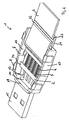
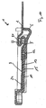
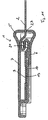
- the Fig. 1 to 8 show a first embodiment of a connector 1 according to the invention for contacting a textile material 2 (see Fig. 2 ), here a textile belt with integrated conductor tracks 3.
- the textile material 2 four interconnects 3 consisting of four individual wires 4 on.
- the conductor tracks 3 are woven into the textile material 2.
- a gluing of the conductor tracks 3 on the textile material 2 or between two layers of textile material is conceivable.
- the conductor tracks 3 are designed as a conductive textile web or as a conductive yarn.
- the fabric 2 is extremely ductile and very thin compared to its longitudinal and transverse extension.
- Connector 1 can be used in all types of flat textiles, for example of synthetic and / or textile fibers.
- the connector 1 comprises a housing 5, which consists of a lower part 6 and a cover part 7 (FIG. Fig. 6 ) consists.
- latching means 8 are provided on the lower part. These are with corresponding counter-locking means 9 ( Fig. 6 ) of the lid part 7 can be latched.
- the connector 1 has a board 10, which is held with clamping means 11 on the bottom 12 of the lower part 6.
- the board 10 has four flat, juxtaposed contacts 13 for contacting the interconnects 3.
- the board 10 is guided to the outside and has on the bottom four contact surfaces 14, which serve for contacting an electrical device.
- the outwardly guided region of the board 10 is located in a plug-in section 15 of the connector 1.
- the connector 1 may be formed for example as a USB plug.
- the bottom 12 of the lower part 6 is surrounded by walls arranged perpendicular thereto, namely two opposite side walls 17 and a front wall 18 connecting the side walls 17 and extending transversely thereto.
- the walls 17, 18 form with the bottom 12 a receiving trough for receiving the textile material 2 and the board 10th
- a film hinge 20 is provided, which connects the lower part 6 of the connector 1 with deflecting means 21 pivotally.
- the deflection means 21 like the housing 5, made of plastic.
- the deflecting means 21 are designed as a flat component with two parallel, in the transverse direction of the connector 1 extending through slots 22, 23.
- the lead-through slots 22, 23 also extend transversely to the longitudinal extent of the band-shaped textile material 2 or transversely to the longitudinal extent of the conductor tracks 3.
- the deflection means 21 are in an insertion position for threading the textile material into the passage slots 22, 23.
- the insertion position is located outside of the receiving trough formed by the bottom 12 and the walls 17, 18.
- the deflection means 21 are located in a plane parallel to a floor 12 receiving level.
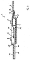
- the textile material 2 is guided by the longitudinal direction of the connector 1, in the insertion rear rear slot 23 from top to bottom and from below the deflection 21 through the front feed slot 22 back up.
- the exposed conductor tracks 3 are in Fig. 2 already welded to the contacts 13 of the connector 1. Exposure may be effected, for example, by melting the textile material in the exposed area at a temperature below the melting temperature of the conductor tracks 3, but above the melting temperature of the textile material 2.
- the conductor tracks 3 connect a front end piece 24 of the textile material 2, which is received within the lower part 6, with the rest of the textile material 2, that is to say with the section of the textile material 2 led out of the connector. This first fastening step is particularly clear in FIGS Fig. 2 and 3 shown.
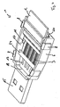
- the deflection means 21 are pivoted by 180 ° by means of the film hinge 20 in the longitudinal direction of the connector 1 to a running in the transverse direction of the connector 1 pivot axis.
- the textile material 2 extends initially above the deflection 21 in the longitudinal direction of the connector 1 along and is then deflected by 90 ° down and past the free end 25 of the deflection 21 and again deflected by 90 ° to the rear and then parallel to the insertion direction, however in connector 1 to the rear.
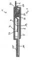
- the textile material 2 is guided by 90 ° up through the feed-through slot 23 and continues in the direction of the rear plug connector end. Thereafter, the textile material 2 is again deflected by 90 ° and deflected by the feed-through slot 22 downwards and then runs again in the direction of the front connector end. There then takes place a further deflection by 90 ° upwards along a deflecting wall 26, which is formed integrally with the lower part 6 and extends orthogonally to the bottom 12 of the lower part 6. At the free end of the deflection wall 26, the textile material is again deflected by 90 ° in the longitudinal direction of the connector 1 and then extends obliquely downward in the direction of the board 10.
- the deflection 21 is in the in Fig.
- the lid part 7 is integrallyklippst on the lower part 6.
- the textile material 2 is clamped between the free end of the deflection wall 26 and the cover part 7. In this area, the textile material 2 is easily guided.
- a slot 27 extending transversely to the longitudinal direction of the connector 1 is formed in the rear region for insertion of the textile material 2 into the housing 5.
- the deflection means 21 are not formed integrally with the housing 5. They consist only of a loose beam portion with a single feed slot 22.
- the attachment is as follows:
- the textile material 2 is passed through the slot 22.
- the deflection means 21 is rotated by 180 ° (see Fig. 10 ), so that the textile material surrounds the deflection means 21 in an S shape, that is to say it is deflected four times by 90 ° (twice by 180 °) at the deflection means.
- the deflection means 21 arranged transversely to the longitudinal extent of the connector 1 is arranged in two opposite retaining grooves 28 of the housing Lower part 6 added. These run perpendicular to the longitudinal extent of the connector 1. In this fixing position of the lead-through slot 22 extends parallel to the longitudinal extension of the connector 1 and thus parallel to the insertion of the textile material 2 in the connector 1 and also parallel to the conductors 3 and the contacts 13 and the board 10th ,
- the textile material used in the second embodiment has only two conductor tracks 3 each having ten helically formed wires 4.
- the textile material 2 is extremely stretchable.
- Fig. 11 the connector 1 is shown with the housing 5 closed.
- the cover part 7 is connected to the lower part 6, glued in this embodiment.
Landscapes
- Coupling Device And Connection With Printed Circuit (AREA)
Description
Die Erfindung betrifft einen elektrischen Steckverbinder zum Kontaktieren mindestens einer in einem Textilmaterial integrierten Leiterbahn.The invention relates to an electrical connector for contacting at least one conductor track integrated in a textile material.
So genannte intelligente Textilien sind auf dem Vormarsch. Derartige Textilien sind mit elektronischen Funktionen versehen und dienen beispielsweise als Fernbedienung für einen MP3-Player. Die Textilien weisen in der Regel mehrere, bevorzugt eingewebte Leiterbahnen auf, die beispielsweise zur Kontaktierung elektronischer Geräte dienen. Häufig sind die Leiterbahnen schraubenförmig ausgeformt und damit extrem längendehnbar. Zum Anschluss der Leiterbahnen an ein elektrisches Gerät werden Steckverbinder eingesetzt, die elektrisch mit den Leiterbahnen des Textilmaterials verbunden, insbesondere verlötet, werden. Beim täglichen Gebrauch des beispielsweise als Jacke ausgebildeten Textilmaterials kommt es aufgrund der ständig auftretenden Zugspannungen häufig zu einem Lösen der Kontaktierung zwischen Steckverbinder und Textilmaterial. Das Vorsehen einer formschlüssigen Zugentlastung, beispielsweise mit das Textilmaterial durchstoßenden Befestigungszähnen ist nicht zielführend, da das in der Regel extrem längendehnbare Textilmaterial in diesem Fall zum Ausreißen neigt.So-called intelligent textiles are on the rise. Such textiles are provided with electronic functions and are used for example as a remote control for an MP3 player. The textiles usually have several, preferably woven conductor tracks, which serve for example for contacting electronic devices. Frequently, the tracks are helically shaped and thus extremely elongated. To connect the conductor tracks to an electrical device, connectors are used which are electrically connected, in particular soldered, to the conductor tracks of the textile material. In the daily use of, for example, formed as a jacket textile material due to the constantly occurring tensile stresses often lead to a loosening of the contact between connector and textile material. The provision of a positive strain relief, for example, with the textile material piercing Fastening teeth is not effective, since the extremely elongated textile usually tends to rip in this case.
Die
Die
Der Erfindung liegt die Aufgabe zugrunde, einen verbesserten elektrischen Steckverbinder zur Kontaktierung der in einem Textilmaterial integrierten Leiterbahnen vorzuschlagen, mit dem ein Lösen der elektrisch leitenden Verbindung auch unter stärksten Beanspruchungen vermieden und gleichzeitig ein Ausreißen des Textilmaterials verhindert wird.The invention has for its object to propose an improved electrical connector for contacting the integrated circuit in a textile material interconnects, with the dissolution of the electrically conductive connection avoided even under the strongest conditions while tearing the fabric is prevented.
Diese Aufgabe wird mit den Merkmalen des Anspruches 1 gelöst.This object is achieved with the features of claim 1.
Vorteilhafte Weiterbildungen der Erfindung sind in den Unteransprüchen angegeben.Advantageous developments of the invention are specified in the subclaims.
Der Erfindung liegt der Gedanke zugrunde, eine reibschlüssige Zugentlastung vorzusehen, mit der das Textilmaterial reibschlüssig in bzw. am Steckverbinder gehalten ist. Erfindungsgemäß sind zur Zugentlastung Umlenkmittel vorgesehen, mit denen das Textilmaterial bevorzugt mehrfach umgelenkt wird, wodurch aufgrund der Umschlingungswinkel eine reibschlüssige Verbindung zwischen Umlenkmitteln und Textilmaterial geschaffen wird. Je öfter die Richtung des Textilmaterials geändert wird, desto größer sind die wirkenden Reibkräfte. Bevorzugt werden große Umschlingungswinkel zwischen Textilmaterial und Umlenkmitteln gewählt, um die reibschlüssige Verbindung zwischen Textilmaterial und Umlenkmitteln weiter zu verbessern.The invention is based on the idea to provide a frictional strain relief, with which the textile material is frictionally held in or on the connector. According to the invention, deflecting means are provided for strain relief, with which the textile material is preferably deflected several times, whereby due to the wrap angle, a frictional connection between deflecting means and textile material is created. The more often the direction of the textile material is changed, the greater the frictional forces acting. Preference is given to large wrap angles between Textile material and deflection selected to further improve the frictional connection between textile material and deflection.
In Ausgestaltung der Erfindung ist mit Vorteil vorgesehen, dass die Umlenkmittel einstückig mit dem Steckverbinder ausgebildet sind. Diese Variante vereinfacht zum einen die Montage und zum anderen die Lagerhaltung, die Logistik und den Transport der elektrischen Steckverbinder. Durch die einstückige Ausbildung der Umlenkmittel mit dem Steckverbinder kann die auf das Textilmaterial wirkende Zugkraft an das Gehäuse des Steckverbinders weitergegeben werden.In an embodiment of the invention is advantageously provided that the deflection means are integrally formed with the connector. This variant simplifies the assembly and the storage, logistics and transport of the electrical connectors. Due to the one-piece design of the deflection means with the connector, the force acting on the textile material tensile force can be passed to the housing of the connector.
Eine Möglichkeit, mindestens eine Richtungsumlenkung des Textilmaterials zu realisieren, besteht darin, das Textilmaterial durch mindestens einen, bevorzugt zwei oder mehr Durchführschlitze innerhalb des Umlenkmittels zu führen. Die Schlitzbreite sollte der Textilmaterialbreite zuzüglich eines Spiels entsprechen.One possibility for realizing at least one directional deflection of the textile material is to guide the textile material through at least one, preferably two or more, through-feed slots within the deflection means. The slot width should match the fabric width plus a clearance.
Gemäß einer bevorzugten Ausführungsform der Erfindung sind die Umlenkmittel schwenkbar mit dem Steckverbinder, insbesondere mit dem Steckverbindergehäuse verbunden, und zwar derart, dass die Umlenkmittel zwischen einer Einführposition, in der das Textilmaterial durch den mindestens einen Durchführschlitz durchführbar ist und einer Fixierposition verschwenkbar ist. Bevorzugt erfolgt eine Verschwenkung um etwa 180°. Hierdurch ist es möglich, dass sich die Einführposition außerhalb des eigentlichen Steckverbinders befindet und dass die Umlenkmittel erst durch Verschwenken, bevorzugt um 180° in den eigentlichen Steckverbinder hinein verschwenkbar sind, wodurch die Montage erheblich erleichtert wird.According to a preferred embodiment of the invention, the deflection means are pivotally connected to the connector, in particular to the connector housing, in such a way that the deflection between an insertion position in which the textile material is passed through the at least one passage slot and a fixing position is pivotable. Preferably, a pivoting takes place by about 180 °. This makes it possible that the insertion is outside the actual connector and that the deflection only by pivoting, preferably by 180 ° in the actual connector are pivotable, whereby the assembly is greatly facilitated.
In Weiterbildung der Erfindung ist mit Vorteil vorgesehen, dass zur schwenkbaren Anbindung der Umlenkmittel an dem Gehäuse mindestens ein Filmscharnier zwischen den Umlenkmitteln und dem Gehäuse vorgesehen ist. Bevorzugt bestehen sowohl Gehäuse als auch Umlenkmittel und Filmscharnier aus Kunststoff. In Ausgestaltung der Erfindung kann vorgesehen werden, dass das Filmscharnier als einfache Materialschwächung und/oder aus einem Material ausgebildet ist, das sich von dem Material der Umlenkmittel und dem Material des Gehäuses unterscheidet. Bevorzugt handelt es sich um einen flexiblen Kunststoff.In a further development of the invention is advantageously provided that at least one film hinge between the deflecting means and the housing is provided for the pivotable connection of the deflection means on the housing. Preferably, both housing and deflecting means and film hinge made of plastic. In an embodiment of the invention can be provided that the film hinge is designed as a simple material weakening and / or of a material that differs from the material of the deflection and the material of the housing. It is preferably a flexible plastic.
Eine optimale reibschlüssige Verbindung zwischen dem Textilmaterial und den Umlenkmitteln wird erreicht, wenn die Umlenkmittel derart ausgebildet oder angeordnet sind, dass das Textilmaterial mindestens zweimal seine Richtung ändert, bevorzugt jedes Mal um etwa 180°, bzw. viermal um 90°.An optimal frictional connection between the textile material and the deflecting means is achieved if the deflection means are designed or arranged such that the textile material changes its direction at least twice, preferably every time by about 180 °, or four times by 90 °.
Zur Erleichterung der Montage ist es zweckmäßig, das Gehäuse mindestens zweiteilig auszubilden, nämlich mit einem Unterteil und einem mit dem Unterteil verrastbaren Deckelteil. Eine optimale reibschlüssige Verbindung zwischen Steckverbinder und Umlenkmitteln kann realisiert werden, wenn das Textilmaterial zusätzlich zwischen Deckelteil und Umlenkmitteln und/oder zwischen Unterteil und Umlenkmitteln geklemmt wird. Bevorzugt erfolgt die Umlenkung mittels der Umlenkmittel derart, dass das Textilmaterial im Bereich der Klemmung zwischen den Umlenkmitteln und dem Deckelteil und/oder dem Unterteil doppelt geführt ist. Hierdurch kann eine verbesserte Klemmwirkung erzielt werden.To facilitate assembly, it is expedient to form the housing at least in two parts, namely with a lower part and a latchable with the lower part of the cover part. An optimal frictional connection between the connector and deflecting means can be realized when the textile material is additionally clamped between the cover part and deflecting means and / or between the lower part and deflecting means. Preferably, the deflection takes place by means of the deflection means such that the textile material is guided twice in the region of the clamping between the deflection means and the cover part and / or the lower part. As a result, an improved clamping effect can be achieved.
Weitere Vorteile und zweckmäßige Ausführungen der Erfindung sind den weiteren Ansprüchen, der Figurenbeschreibung und den Zeichnungen zu entnehmen. Es zeigen:
- Fig. 1
- eine perspektivische Darstellung eines Unterteils eines erfindungsgemäßen Steckverbinders mit schwenkbar angelenkten Umlenkmitteln in einer Einführposition,
- Fig. 2
- das Unterteil gemäß
Fig. 1 mit eingelegtem Textilmaterial, mit sich noch in Einführposition befindlichen Umlenkmitteln, - Fig. 3
- eine geschnittene Seitenansicht der in
Fig. 2 dargestellten Befestigungssituation, - Fig. 4
- eine perspektivische Ansicht des Unterteils mit befestigtem Textilmaterial, wobei die Umlenkmittel in eine Fixierposition innerhalb des Unterteils verschwenkt sind,
- Fig. 5
- eine geschnittene Seitenansicht der Befestigungssituation gemäß
Fig. 4 , - Fig. 6
- der elektrische Steckverbinder mit geschlossenem Gehäuse,
- Fig. 7
- eine geschnittene Seitenansicht des Steckverbinders gemäß
Fig. 6 , - Fig. 8
- ein zweites Ausführungsbeispiel eines Steckverbinders mit eingelegtem Textilmaterial in einer Draufsicht,
- Fig. 9
- die Umlenkmittel des Steckverbinders gemäß
Fig. 8 , - Fig. 10
- eine geschnittene Seitenansicht des Unterteils des Steckverbinders gemäß dem zweiten Ausführungsbeispiel mit eingelegtem Textilmaterial und
- Fig. 11
- der geschlossene Steckverbinder gemäß dem zweiten Ausführungsbeispiel.
- Fig. 1
- a perspective view of a lower part of a connector according to the invention with pivotally hinged deflection in an insertion position,
- Fig. 2
- the lower part according to
Fig. 1 with inserted textile material, with deflection means still in the insertion position, - Fig. 3
- a sectional side view of the
Fig. 2 illustrated attachment situation, - Fig. 4
- a perspective view of the lower part with attached textile material, wherein the deflection means are pivoted into a fixing position within the lower part,
- Fig. 5
- a sectional side view of the attachment situation according to
Fig. 4 . - Fig. 6
- the electrical connector with closed housing,
- Fig. 7
- a sectional side view of the connector according to
Fig. 6 . - Fig. 8
- A second embodiment of a connector with inserted textile material in a plan view,
- Fig. 9
- the deflection of the connector according to
Fig. 8 . - Fig. 10
- a sectional side view of the lower part of the connector according to the second embodiment with inserted textile material and
- Fig. 11
- the closed connector according to the second embodiment.
In den Figuren sind gleiche Bauteile und Bauteile mit gleicher Funktion mit den gleichen Bezugszeichen gekennzeichnet.In the figures, the same components and components with the same function with the same reference numerals.
Die
Der Steckverbinder 1 umfasst ein Gehäuse 5, welches aus einem Unterteil 6 und einem Deckelteil 7 (
Der Steckverbinder 1 weist eine Platine 10 auf, die mit Klemmmitteln 11 am Boden 12 des Unterteils 6 gehalten ist. Die Platine 10 weist vier flache, nebeneinander angeordnete Kontakte 13 zur Kontaktierung der Leiterbahnen 3 auf. Wie in
Der Boden 12 des Unterteils 6 ist von senkrecht dazu angeordneten Wänden, nämlich zwei gegenüberliegenden Seitenwänden 17 und einer die Seitenwände 17 miteinander verbindenden, quer zu diesen verlaufenden Frontwand 18 umgeben. Die Wände 17, 18 bilden mit dem Boden 12 eine Aufnahmemulde zur Aufnahme des Textilmaterials 2 und der Platine 10.The bottom 12 of the
An einer hinteren Kante 19 des Unterteils 6 ist ein Filmscharnier 20 vorgesehen, das das Unterteil 6 des Steckverbinders 1 mit Umlenkmitteln 21 schwenkbar verbindet. Die Umlenkmittel 21 sind, wie das Gehäuse 5, aus Kunststoff ausgebildet. Die Umlenkmittel 21 sind als flächiges Bauteil mit zwei parallelen, in Querrichtung des Steckverbinders 1 verlaufenden Durchführschlitzen 22, 23 ausgeführt. Damit verlaufen die Durchführschlitze 22, 23 auch quer zur Längserstreckung des bandförmigen Textilmaterials 2 bzw. quer zur Längserstreckung der Leiterbahnen 3.At a
In
Wie aus
Zunächst wird das Textilmaterial 2 durch den in Längsrichtung des Steckverbinders 1 gesehenen, in der Einführposition hinteren Durchführschlitz 23 von oben nach unten geführt und von unterhalb der Umlenkmittel 21 durch den vorderen Durchführschlitz 22 wieder nach oben. Die freigelegten Leiterbahnen 3 sind in
In einem nächsten, in den
In den
Bei dem in den
Zunächst wird das Textilmaterial 2 durch den Schlitz 22 hindurchgeführt. Daraufhin wird das Umlenkmittel 21 um 180° gedreht (siehe
Das bei dem zweiten Ausführungsbeispiel verwendete Textilmaterial weist lediglich zwei Leiterbahnen 3 mit jeweils zehn schraubenförmig ausgebildeten Drähten 4 auf. Das Textilmaterial 2 ist extrem längendehnbar.The textile material used in the second embodiment has only two
In
Wie aus
- 11
- SteckverbinderConnectors
- 22
- Textilmaterialtextile material
- 33
- Leiterbahnenconductor tracks
- 44
- Drähtewires
- 55
- Gehäusecasing
- 66
- Unterteillower part
- 77
- DecktelteilDecktelteil
- 88th
- Rastmittellatching means
- 99
- GegenrastmittelSecuring means
- 1010
- Platinecircuit board
- 1111
- Klemmmittelclamping means
- 1212
- Bodenground
- 1313
- Kontaktecontacts
- 1414
- Kontaktflächecontact area
- 1515
- Steckabschnittplug-in section
- 1616
- Umlenkmitteldeflecting
- 1717
- Seitenwändeside walls
- 1818
- Frontwandfront wall
- 1919
- hintere Kanterear edge
- 2020
- Filmscharnierfilm hinge
- 2121
- Umlenkmitteldeflecting
- 2222
- DurchführschlitzThrough-slot
- 2323
- DurchführschlitzThrough-slot
- 2424
- vorderes Endstückfront tail
- 2525
- freies Endefree end
- 2626
- Umlenkwandbaffle
- 2727
- Schlitzslot
- 2828
- Haltenutenretaining
Claims (12)
- An electrical plug-in connector (1) with a housing (5) and with at least one electrical contact (13) for making contact with at least one printed conductor (3) which is integrated in a textile material (2), characterized in that
there are deflection means (21) for the textile material (2) for causing a frictionally engaged connection between the plug-in connector (1) and the textile material (2). - The electrical plug-in connector as claimed in Claim 1, wherein the deflection means (21) are made integral with the plug-in connector (2).
- The electrical plug-in connector as claimed in Claim 2, wherein the deflection means (21) have at least one through slot (22, 23) for feeding the textile material (2) through.
- The electrical plug-in connector as claimed in one of the preceding claims, wherein the deflection means (21) are connected to be able to pivot, especially by 180°, to the housing (5), and wherein the deflection means (21) can be swiveled between an insertion position and a fixing position.
- The electrical plug-in connector as claimed in Claim 4, wherein there is at least one film hinge (20) between the deflection means (21) and the housing (5) for pivotable linkage of the deflection means (21) to the housing (5).
- The electrical plug-in connector as claimed in Claim 5, wherein the film hinge (20) is formed as a material weakening and/or from a preferably more flexible material which is different from the housing material.
- The electrical plug-in connector as claimed in one of the preceding claims, wherein the deflection means (21) are made to deflect the textile material (2) at least twice, preferably by 180° at a time.
- The electrical plug-in connector as claimed in one of the preceding claims, wherein the housing (5) has a lower part (6) and a cover part (7) which can be latched preferably to the lower part (6).
- The electrical plug-in connector as claimed in Claim 8, wherein the textile material (2) is held by clamping between the cover part (7) and the deflection means (21) and/or between the lower part (6) and the deflection means (21).
- The electrical plug-in connector as claimed in one of the preceding claims, wherein the deflection means (21) are located in the rear region of the plug-in connector (1).
- A combination of an electrical plug-in connector (1) as claimed in one of the preceding claims and a textile material (2) with at least one integrated printed conductor (3), the textile material being connected by frictional engagement to deflection means (21) of the plug-in connector (1).
- Use of an electrical plug-in connector (1) as claimed in one of Claims 1 to 10 for making contact with at least one printed conductor (3) which is surrounded by a textile material and for frictionally engaged linkage of the printed conductor (3).
Applications Claiming Priority (2)
| Application Number | Priority Date | Filing Date | Title |
|---|---|---|---|
| DE200610019269 DE102006019269A1 (en) | 2006-04-26 | 2006-04-26 | Electrical plug-in connector for e.g. contacting strip conductor, has enclosure with lower part and cover part, switching units for textile material and provided for producing frictional connection between connector and textile material |
| PCT/EP2007/003530 WO2007124880A1 (en) | 2006-04-26 | 2007-04-23 | Textile plug-type connector |
Publications (2)
| Publication Number | Publication Date |
|---|---|
| EP2011192A1 EP2011192A1 (en) | 2009-01-07 |
| EP2011192B1 true EP2011192B1 (en) | 2013-03-13 |
Family
ID=38144404
Family Applications (1)
| Application Number | Title | Priority Date | Filing Date |
|---|---|---|---|
| EP07724460A Not-in-force EP2011192B1 (en) | 2006-04-26 | 2007-04-23 | Textile plug-type connector |
Country Status (3)
| Country | Link |
|---|---|
| EP (1) | EP2011192B1 (en) |
| DE (1) | DE102006019269A1 (en) |
| WO (1) | WO2007124880A1 (en) |
Families Citing this family (2)
| Publication number | Priority date | Publication date | Assignee | Title |
|---|---|---|---|---|
| US8376759B2 (en) | 2010-09-20 | 2013-02-19 | Tyco Electronics Corporation | Connectors for E-textiles |
| AU2015248452A1 (en) | 2014-04-18 | 2016-11-24 | Healthwatch Ltd. | Connector and cable assembly for smart garments |
Citations (1)
| Publication number | Priority date | Publication date | Assignee | Title |
|---|---|---|---|---|
| WO2005002001A1 (en) * | 2003-06-30 | 2005-01-06 | Koninklijke Philips Electronics, N.V. | A textile interconnect |
Family Cites Families (2)
| Publication number | Priority date | Publication date | Assignee | Title |
|---|---|---|---|---|
| JP2001210409A (en) * | 2000-01-28 | 2001-08-03 | Yazaki Corp | Connector for flat circuit body and connection structure of flat circuit body to connector |
| US6538207B1 (en) * | 2002-01-18 | 2003-03-25 | Agilent Technologies, Inc. | Strain relief structures for lead connections |
-
2006
- 2006-04-26 DE DE200610019269 patent/DE102006019269A1/en not_active Withdrawn
-
2007
- 2007-04-23 WO PCT/EP2007/003530 patent/WO2007124880A1/en not_active Ceased
- 2007-04-23 EP EP07724460A patent/EP2011192B1/en not_active Not-in-force
Patent Citations (1)
| Publication number | Priority date | Publication date | Assignee | Title |
|---|---|---|---|---|
| WO2005002001A1 (en) * | 2003-06-30 | 2005-01-06 | Koninklijke Philips Electronics, N.V. | A textile interconnect |
Also Published As
| Publication number | Publication date |
|---|---|
| WO2007124880A1 (en) | 2007-11-08 |
| EP2011192A1 (en) | 2009-01-07 |
| DE102006019269A1 (en) | 2007-10-31 |
Similar Documents
| Publication | Publication Date | Title |
|---|---|---|
| DE19731455C2 (en) | Connector attachment structure | |
| DE60306643T2 (en) | An electrical connector having improved function of both the magnetic shield and the ground connection | |
| EP1950836B1 (en) | Electrical terminal | |
| DE4222452A1 (en) | SHIELDED CONNECTOR | |
| EP3164911A1 (en) | Plug | |
| DE3244939C1 (en) | Lockable electrical flat receptacle and electrical connector provided with it | |
| WO1997008785A1 (en) | Flat cable plug connecting device | |
| DE102017110546B3 (en) | Tensile and pressure relief means for a connector housing | |
| EP1656717B1 (en) | Flat cable connector arrangement | |
| EP3116074B1 (en) | Plug socket module | |
| WO2007131631A1 (en) | Module with connectors for actuators and/or sensors | |
| EP2011192B1 (en) | Textile plug-type connector | |
| DE112019002694B4 (en) | connector | |
| EP0122314A2 (en) | Multipole plug | |
| DE102015113512B3 (en) | Clamping arrangement and spring clamp | |
| DE602004008094T2 (en) | ELECTRICAL CONNECTOR FOR A FLEXIBLE FLAT LEADER AND SWITCHING DEVICE | |
| EP1091457A2 (en) | Electrical connector element and system | |
| DE69706858T2 (en) | ELECTRICAL CONNECTOR WITH ONE-PIECE SECONDARY LOCKING ELEMENT | |
| DE3118574A1 (en) | ELECTRICAL CONTACT AND ELECTRICAL PLUG ARRANGEMENT | |
| DE29907005U1 (en) | Connection and / or connection terminal for an electrical device | |
| DE29623742U1 (en) | Electrical connector, in particular for printed circuit boards | |
| LU500693B1 (en) | Connector part with a shield support | |
| DE10134562A1 (en) | System and method for electrical contacting and mechanical fastening of printed circuit boards | |
| DE19830635C1 (en) | Mains connector with spark suppression for electrical equipment has lug protruding from suppresser housing with earth connector forming mains cable strain reliever with mounting plate | |
| DE202024105808U1 (en) | Cable outlet and electrical device with the same |
Legal Events
| Date | Code | Title | Description |
|---|---|---|---|
| PUAI | Public reference made under article 153(3) epc to a published international application that has entered the european phase |
Free format text: ORIGINAL CODE: 0009012 |
|
| 17P | Request for examination filed |
Effective date: 20080908 |
|
| AK | Designated contracting states |
Kind code of ref document: A1 Designated state(s): AT BE BG CH CY CZ DE DK EE ES FI FR GB GR HU IE IS IT LI LT LU LV MC MT NL PL PT RO SE SI SK TR |
|
| AX | Request for extension of the european patent |
Extension state: AL BA HR MK RS |
|
| 17Q | First examination report despatched |
Effective date: 20101103 |
|
| DAX | Request for extension of the european patent (deleted) | ||
| GRAP | Despatch of communication of intention to grant a patent |
Free format text: ORIGINAL CODE: EPIDOSNIGR1 |
|
| GRAS | Grant fee paid |
Free format text: ORIGINAL CODE: EPIDOSNIGR3 |
|
| GRAA | (expected) grant |
Free format text: ORIGINAL CODE: 0009210 |
|
| AK | Designated contracting states |
Kind code of ref document: B1 Designated state(s): AT BE BG CH CY CZ DE DK EE ES FI FR GB GR HU IE IS IT LI LT LU LV MC MT NL PL PT RO SE SI SK TR |
|
| REG | Reference to a national code |
Ref country code: GB Ref legal event code: FG4D Free format text: NOT ENGLISH |
|
| REG | Reference to a national code |
Ref country code: AT Ref legal event code: REF Ref document number: 601282 Country of ref document: AT Kind code of ref document: T Effective date: 20130315 Ref country code: CH Ref legal event code: EP |
|
| REG | Reference to a national code |
Ref country code: IE Ref legal event code: FG4D Free format text: LANGUAGE OF EP DOCUMENT: GERMAN |
|
| REG | Reference to a national code |
Ref country code: DE Ref legal event code: R096 Ref document number: 502007011459 Country of ref document: DE Effective date: 20130508 |
|
| PG25 | Lapsed in a contracting state [announced via postgrant information from national office to epo] |
Ref country code: ES Free format text: LAPSE BECAUSE OF FAILURE TO SUBMIT A TRANSLATION OF THE DESCRIPTION OR TO PAY THE FEE WITHIN THE PRESCRIBED TIME-LIMIT Effective date: 20130624 Ref country code: BG Free format text: LAPSE BECAUSE OF FAILURE TO SUBMIT A TRANSLATION OF THE DESCRIPTION OR TO PAY THE FEE WITHIN THE PRESCRIBED TIME-LIMIT Effective date: 20130613 Ref country code: LT Free format text: LAPSE BECAUSE OF FAILURE TO SUBMIT A TRANSLATION OF THE DESCRIPTION OR TO PAY THE FEE WITHIN THE PRESCRIBED TIME-LIMIT Effective date: 20130313 Ref country code: SE Free format text: LAPSE BECAUSE OF FAILURE TO SUBMIT A TRANSLATION OF THE DESCRIPTION OR TO PAY THE FEE WITHIN THE PRESCRIBED TIME-LIMIT Effective date: 20130313 |
|
| REG | Reference to a national code |
Ref country code: NL Ref legal event code: VDEP Effective date: 20130313 |
|
| REG | Reference to a national code |
Ref country code: LT Ref legal event code: MG4D |
|
| PG25 | Lapsed in a contracting state [announced via postgrant information from national office to epo] |
Ref country code: FI Free format text: LAPSE BECAUSE OF FAILURE TO SUBMIT A TRANSLATION OF THE DESCRIPTION OR TO PAY THE FEE WITHIN THE PRESCRIBED TIME-LIMIT Effective date: 20130313 Ref country code: LV Free format text: LAPSE BECAUSE OF FAILURE TO SUBMIT A TRANSLATION OF THE DESCRIPTION OR TO PAY THE FEE WITHIN THE PRESCRIBED TIME-LIMIT Effective date: 20130313 Ref country code: SI Free format text: LAPSE BECAUSE OF FAILURE TO SUBMIT A TRANSLATION OF THE DESCRIPTION OR TO PAY THE FEE WITHIN THE PRESCRIBED TIME-LIMIT Effective date: 20130313 Ref country code: GR Free format text: LAPSE BECAUSE OF FAILURE TO SUBMIT A TRANSLATION OF THE DESCRIPTION OR TO PAY THE FEE WITHIN THE PRESCRIBED TIME-LIMIT Effective date: 20130614 |
|
| BERE | Be: lapsed |
Owner name: AMPHENOL-TUCHEL ELECTRONICS G.M.B.H. Effective date: 20130430 |
|
| PG25 | Lapsed in a contracting state [announced via postgrant information from national office to epo] |
Ref country code: RO Free format text: LAPSE BECAUSE OF FAILURE TO SUBMIT A TRANSLATION OF THE DESCRIPTION OR TO PAY THE FEE WITHIN THE PRESCRIBED TIME-LIMIT Effective date: 20130313 Ref country code: EE Free format text: LAPSE BECAUSE OF FAILURE TO SUBMIT A TRANSLATION OF THE DESCRIPTION OR TO PAY THE FEE WITHIN THE PRESCRIBED TIME-LIMIT Effective date: 20130313 Ref country code: IS Free format text: LAPSE BECAUSE OF FAILURE TO SUBMIT A TRANSLATION OF THE DESCRIPTION OR TO PAY THE FEE WITHIN THE PRESCRIBED TIME-LIMIT Effective date: 20130713 Ref country code: CZ Free format text: LAPSE BECAUSE OF FAILURE TO SUBMIT A TRANSLATION OF THE DESCRIPTION OR TO PAY THE FEE WITHIN THE PRESCRIBED TIME-LIMIT Effective date: 20130313 Ref country code: PT Free format text: LAPSE BECAUSE OF FAILURE TO SUBMIT A TRANSLATION OF THE DESCRIPTION OR TO PAY THE FEE WITHIN THE PRESCRIBED TIME-LIMIT Effective date: 20130715 Ref country code: SK Free format text: LAPSE BECAUSE OF FAILURE TO SUBMIT A TRANSLATION OF THE DESCRIPTION OR TO PAY THE FEE WITHIN THE PRESCRIBED TIME-LIMIT Effective date: 20130313 Ref country code: NL Free format text: LAPSE BECAUSE OF FAILURE TO SUBMIT A TRANSLATION OF THE DESCRIPTION OR TO PAY THE FEE WITHIN THE PRESCRIBED TIME-LIMIT Effective date: 20130313 |
|
| PG25 | Lapsed in a contracting state [announced via postgrant information from national office to epo] |
Ref country code: PL Free format text: LAPSE BECAUSE OF FAILURE TO SUBMIT A TRANSLATION OF THE DESCRIPTION OR TO PAY THE FEE WITHIN THE PRESCRIBED TIME-LIMIT Effective date: 20130313 Ref country code: CY Free format text: LAPSE BECAUSE OF FAILURE TO SUBMIT A TRANSLATION OF THE DESCRIPTION OR TO PAY THE FEE WITHIN THE PRESCRIBED TIME-LIMIT Effective date: 20130313 |
|
| REG | Reference to a national code |
Ref country code: CH Ref legal event code: PL |
|
| PG25 | Lapsed in a contracting state [announced via postgrant information from national office to epo] |
Ref country code: MC Free format text: LAPSE BECAUSE OF FAILURE TO SUBMIT A TRANSLATION OF THE DESCRIPTION OR TO PAY THE FEE WITHIN THE PRESCRIBED TIME-LIMIT Effective date: 20130313 |
|
| PLBE | No opposition filed within time limit |
Free format text: ORIGINAL CODE: 0009261 |
|
| STAA | Information on the status of an ep patent application or granted ep patent |
Free format text: STATUS: NO OPPOSITION FILED WITHIN TIME LIMIT |
|
| REG | Reference to a national code |
Ref country code: IE Ref legal event code: MM4A |
|
| PG25 | Lapsed in a contracting state [announced via postgrant information from national office to epo] |
Ref country code: CH Free format text: LAPSE BECAUSE OF NON-PAYMENT OF DUE FEES Effective date: 20130430 Ref country code: BE Free format text: LAPSE BECAUSE OF NON-PAYMENT OF DUE FEES Effective date: 20130430 Ref country code: LI Free format text: LAPSE BECAUSE OF NON-PAYMENT OF DUE FEES Effective date: 20130430 Ref country code: DK Free format text: LAPSE BECAUSE OF FAILURE TO SUBMIT A TRANSLATION OF THE DESCRIPTION OR TO PAY THE FEE WITHIN THE PRESCRIBED TIME-LIMIT Effective date: 20130313 |
|
| 26N | No opposition filed |
Effective date: 20131216 |
|
| PG25 | Lapsed in a contracting state [announced via postgrant information from national office to epo] |
Ref country code: IT Free format text: LAPSE BECAUSE OF FAILURE TO SUBMIT A TRANSLATION OF THE DESCRIPTION OR TO PAY THE FEE WITHIN THE PRESCRIBED TIME-LIMIT Effective date: 20130313 |
|
| REG | Reference to a national code |
Ref country code: DE Ref legal event code: R097 Ref document number: 502007011459 Country of ref document: DE Effective date: 20131216 |
|
| PG25 | Lapsed in a contracting state [announced via postgrant information from national office to epo] |
Ref country code: IE Free format text: LAPSE BECAUSE OF NON-PAYMENT OF DUE FEES Effective date: 20130423 |
|
| REG | Reference to a national code |
Ref country code: AT Ref legal event code: MM01 Ref document number: 601282 Country of ref document: AT Kind code of ref document: T Effective date: 20130423 |
|
| PG25 | Lapsed in a contracting state [announced via postgrant information from national office to epo] |
Ref country code: AT Free format text: LAPSE BECAUSE OF NON-PAYMENT OF DUE FEES Effective date: 20130423 |
|
| PG25 | Lapsed in a contracting state [announced via postgrant information from national office to epo] |
Ref country code: MT Free format text: LAPSE BECAUSE OF FAILURE TO SUBMIT A TRANSLATION OF THE DESCRIPTION OR TO PAY THE FEE WITHIN THE PRESCRIBED TIME-LIMIT Effective date: 20130313 |
|
| PG25 | Lapsed in a contracting state [announced via postgrant information from national office to epo] |
Ref country code: TR Free format text: LAPSE BECAUSE OF FAILURE TO SUBMIT A TRANSLATION OF THE DESCRIPTION OR TO PAY THE FEE WITHIN THE PRESCRIBED TIME-LIMIT Effective date: 20130313 |
|
| PG25 | Lapsed in a contracting state [announced via postgrant information from national office to epo] |
Ref country code: LU Free format text: LAPSE BECAUSE OF NON-PAYMENT OF DUE FEES Effective date: 20130423 Ref country code: HU Free format text: LAPSE BECAUSE OF FAILURE TO SUBMIT A TRANSLATION OF THE DESCRIPTION OR TO PAY THE FEE WITHIN THE PRESCRIBED TIME-LIMIT; INVALID AB INITIO Effective date: 20070423 |
|
| REG | Reference to a national code |
Ref country code: FR Ref legal event code: PLFP Year of fee payment: 10 |
|
| REG | Reference to a national code |
Ref country code: FR Ref legal event code: PLFP Year of fee payment: 11 |
|
| PGFP | Annual fee paid to national office [announced via postgrant information from national office to epo] |
Ref country code: FR Payment date: 20170424 Year of fee payment: 11 Ref country code: DE Payment date: 20170425 Year of fee payment: 11 Ref country code: GB Payment date: 20170425 Year of fee payment: 11 |
|
| REG | Reference to a national code |
Ref country code: DE Ref legal event code: R119 Ref document number: 502007011459 Country of ref document: DE |
|
| GBPC | Gb: european patent ceased through non-payment of renewal fee |
Effective date: 20180423 |
|
| PG25 | Lapsed in a contracting state [announced via postgrant information from national office to epo] |
Ref country code: DE Free format text: LAPSE BECAUSE OF NON-PAYMENT OF DUE FEES Effective date: 20181101 |
|
| PG25 | Lapsed in a contracting state [announced via postgrant information from national office to epo] |
Ref country code: GB Free format text: LAPSE BECAUSE OF NON-PAYMENT OF DUE FEES Effective date: 20180423 |
|
| PG25 | Lapsed in a contracting state [announced via postgrant information from national office to epo] |
Ref country code: FR Free format text: LAPSE BECAUSE OF NON-PAYMENT OF DUE FEES Effective date: 20180430 |