EP2010802B1 - Energy conduction chain - Google Patents
Energy conduction chain Download PDFInfo
- Publication number
- EP2010802B1 EP2010802B1 EP07722235.4A EP07722235A EP2010802B1 EP 2010802 B1 EP2010802 B1 EP 2010802B1 EP 07722235 A EP07722235 A EP 07722235A EP 2010802 B1 EP2010802 B1 EP 2010802B1
- Authority
- EP
- European Patent Office
- Prior art keywords
- energy guiding
- rollers
- guiding chain
- tongue
- chain according
- Prior art date
- Legal status (The legal status is an assumption and is not a legal conclusion. Google has not performed a legal analysis and makes no representation as to the accuracy of the status listed.)
- Active
Links
Images

Classifications
-
- F—MECHANICAL ENGINEERING; LIGHTING; HEATING; WEAPONS; BLASTING
- F16—ENGINEERING ELEMENTS AND UNITS; GENERAL MEASURES FOR PRODUCING AND MAINTAINING EFFECTIVE FUNCTIONING OF MACHINES OR INSTALLATIONS; THERMAL INSULATION IN GENERAL
- F16L—PIPES; JOINTS OR FITTINGS FOR PIPES; SUPPORTS FOR PIPES, CABLES OR PROTECTIVE TUBING; MEANS FOR THERMAL INSULATION IN GENERAL
- F16L3/00—Supports for pipes, cables or protective tubing, e.g. hangers, holders, clamps, cleats, clips, brackets
- F16L3/01—Supports for pipes, cables or protective tubing, e.g. hangers, holders, clamps, cleats, clips, brackets for supporting or guiding the pipes, cables or protective tubing, between relatively movable points, e.g. movable channels
- F16L3/015—Supports for pipes, cables or protective tubing, e.g. hangers, holders, clamps, cleats, clips, brackets for supporting or guiding the pipes, cables or protective tubing, between relatively movable points, e.g. movable channels using articulated- or supple-guiding elements
-
- F—MECHANICAL ENGINEERING; LIGHTING; HEATING; WEAPONS; BLASTING
- F16—ENGINEERING ELEMENTS AND UNITS; GENERAL MEASURES FOR PRODUCING AND MAINTAINING EFFECTIVE FUNCTIONING OF MACHINES OR INSTALLATIONS; THERMAL INSULATION IN GENERAL
- F16G—BELTS, CABLES, OR ROPES, PREDOMINANTLY USED FOR DRIVING PURPOSES; CHAINS; FITTINGS PREDOMINANTLY USED THEREFOR
- F16G13/00—Chains
- F16G13/12—Hauling- or hoisting-chains so called ornamental chains
- F16G13/16—Hauling- or hoisting-chains so called ornamental chains with arrangements for holding electric cables, hoses, or the like
-
- F—MECHANICAL ENGINEERING; LIGHTING; HEATING; WEAPONS; BLASTING
- F16—ENGINEERING ELEMENTS AND UNITS; GENERAL MEASURES FOR PRODUCING AND MAINTAINING EFFECTIVE FUNCTIONING OF MACHINES OR INSTALLATIONS; THERMAL INSULATION IN GENERAL
- F16G—BELTS, CABLES, OR ROPES, PREDOMINANTLY USED FOR DRIVING PURPOSES; CHAINS; FITTINGS PREDOMINANTLY USED THEREFOR
- F16G15/00—Chain couplings, Shackles; Chain joints; Chain links; Chain bushes
- F16G15/12—Chain links
-
- H—ELECTRICITY
- H02—GENERATION; CONVERSION OR DISTRIBUTION OF ELECTRIC POWER
- H02G—INSTALLATION OF ELECTRIC CABLES OR LINES, OR OF COMBINED OPTICAL AND ELECTRIC CABLES OR LINES
- H02G11/00—Arrangements of electric cables or lines between relatively-movable parts
- H02G11/006—Arrangements of electric cables or lines between relatively-movable parts using extensible carrier for the cable, e.g. self-coiling spring
Definitions
- the invention relates to an energy transmission chain according to the preamble of the main claim.
- Such energy drag chains are for example from the DE 19919076 A1 and the DE 4313075 A1 known. They generally consist of two strands of side flaps, which are connected to one another so that they are pivotable against each other, and two or more 'transverse webs, each connecting two side flaps of the two strands together to form a chain link.
- the side flaps can either be different, with largely flat inner flaps alternating with outer flaps in one strand, or they can be the same and, for example, each have an outwardly and an inwardly bent region.
- the power supply chain provided with supply lines is fixed at one end to a stationary supply source and at the other end to a mobile consumer and can be moved to form a lower run and a partially slid upper run over a deflection area in one Loop together. Desirable properties of the energy chain are high smoothness and low friction losses during the process.
- the smoothness of the energy chain can be improved if you store as many links on a certain length, ie the chain links designed as short as possible.
- the GB 1444307 discloses an energy chain, in the individual chain links a Support surface is assigned, which is aligned so that it forms a plane together with the other support surfaces on the inside of the loop.
- Certain chain links are provided with rollers which project beyond the support surface with their circumferential surface and roll on the opposite support surface during the process of the upper strand on the lower strand.
- WO 99/57457 A1 proposes to provide the peripheral surfaces of these rollers with a guide profile in the form of circumferential grooves with intermediate ridges, which engage in the grooves of the opposite rollers and can prevent uncontrolled lateral displacement of the upper strand.
- Object of the present invention is to provide an energy guide chain with rollers, which has a high level of smoothness and can be moved evenly and with minimal noise.
- the solution according to the invention makes it possible for one section of the side flap, which has the sliding roller and can be connected to the adjacent side flap, to be directly adjacent to the other section which can be connected to the side flap adjacent to the other side or even intersects therewith.
- the length of the roller-carrying chain links to the length of To match other chain links, creating a smooth flow with low noise and the smoothness of the chain can be set within limits by selecting the chain link length.
- This embodiment is preferred, although the invention may be practiced with more or less different lengths of roller-carrying chain links.
- the rollers are fastened to the outside of the side flaps, widenings being provided as running surfaces for the rollers on the inside of the loop of the side flaps.
- the rollers are mounted so that their axis of rotation coincides with the pivot axis of a side flap pair.
- the rollers can be advantageously incorporated in the interior of the side flaps, wherein the narrow sides of the flaps serve as a running surface.
- the side strap strands of the energy guiding chain according to the invention consist for the most part of tabs which are identical to one another and which each have one (viewed from the chain link) to the outside and an inwardly bent region.
- the chain of the inwardly cranked portion of a tab is then placed on the outwardly bent portion of the next tab and both pivotally connected to each other, for example, by an inserted into a receptacle pivot pin.
- side flaps with rollers are incorporated into such a strand, then it is advantageous to customize adapted to the region of the next flap to be connected to the roller-carrying area, so that a roll-carrying side flap pair results for incorporation into the side flaps strand.
- the end portions of this side tab pair are then again designed so that they are bent with the example inwardly or outwardly Area of mutually identical tabs are connectable.
- such a side flap pair preferably consists of a first side flap which has a region which is connectable to a rollless side flap and a tongue which carries at least one roll and a second side flap which has a region connectable to a rollless side flap. and a guide area.
- the tongue can be connected to the guide region so that both side flaps can be pivoted about an axis coincident with the axis of the roller.
- the regions of the first and second side flaps which can be connected to the rollless side flaps are complementary to one another. Then, such a side tab pair can also be incorporated into an existing strand of the same side tabs described above.
- the guide region of the second side flap is preferably formed by one or two cheeks, which extend, for example, in continuation of the side surfaces of the second side flap and leave an interior space free.
- the cheeks may receive means for pivotally connecting the tongue with them. These means may be, for example, pins attached to the tongue or the like.
- Preferably, circular openings are provided in the cheeks, inserted into the discs and fixed to the tongue, for. B. can be screwed.
- These discs may have a flange resting on the cheek for further stabilization on the outer face.
- the guide portion is formed by two cheeks, between which the tongue can be inserted with the at least one roller, so that the roller with a part its peripheral region protrudes from the guide area.
- rollers are attached to both sides of the tongue.
- the pairs of rollers thus formed delimit between them a guide groove, which serves the lateral guidance des.Obertrums.
- the attachment to the tongue is preferably carried out by plugging on pins on the tongue.
- the rollers are ball-bearing.
- the pivot axis for adjacent side flaps is arranged asymmetrically so that it lies closer to the running surface than to the opposite narrow side of the side flaps.
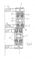
- FIG. 1 is a section of an energy guiding chain according to the invention with Untertrum 1 and upper strand 2 shown in view of the outside of one of the side strap strands.
- the strand consists for the most part of mutually equal side flaps 3. Included are roller-carrying side flap pairs 4, which consist of first side flaps 5 and second side flaps 6.
- the sectional view FIG. 2 corresponds to an operating condition in which the roles of Untertrum 1 and upper strand 2 are exactly superimposed.
- the guide portion 7 of the second side flap of the roll-carrying side flap pair extends into two cheeks 8, between which the tongue 9 of the first side flap is inserted. This is formed on both sides with pins 10, are mounted on the ball-bearing rollers 11, 12. These protrude with its peripheral region of the tread 16 and roll on the opposite tread.
- the tongue with the guide portion 7 is pivotally connected.
- the transverse webs 14 make the connection to the other side strap strand and together form with both strands the space for receiving the supply lines.
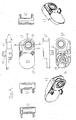
- FIG. 3 shows the first side flap of the roller-carrying side flap pair in orientation in the lower run 1 in plan view (ie on the tread 16) a), rear view (ie from the inside of the chain link) c), bottom view f), front view g), left side view b), right Side view d), section II-II e), and the rear view in perspective to the left h) and right i).
- the tongue 9 with the pin 10 serves the Receiving the rollers (not shown here)
- the area 22 under the outer surface 20 serves for connection to the other mutually equal side tabs by means of the recess 18, which can receive a corresponding pivot pin.
- the holes 21 in the pin 10 are provided for screws for fixing a disc, not shown here.
- transverse webs 14 FIG. 2 ) are plugged.
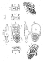
- FIG. 4 shows the second side flap of the roll-carrying side flap pair in orientation in the lower run 1 in plan view (ie on the tread 16) a), rear view (ie from the inside of the chain link) c), bottom view f), front view g), left side view b), right side view d), section II-II e), and the rear view in perspective to the left h) and right i).
- the guide portion 7 extends into the cheeks 8, which are provided with openings 24 for receiving the mounting plate, not shown here.
- the connecting portion 25 is provided here in the middle with a pivot pin 26 which can be accommodated in a receptacle of an adjacent side tab, the receptacle 18 (FIG. FIG. 3 ) corresponds.
- the connection region 25 on the second side flap is thus complementary to the connection region 22 on the first side flap.
- the smooth outer surface 23 of the connection region points here to the interior of the chain link.
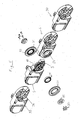
- FIG. 5 shows an exploded view of the roller-carrying side flap pair of first and second side flap 5 and 6 and two at its two ends of adjacent tabs 30 of a side strap strand of the energy supply chain according to the invention.
- the tongue 9 of the first side flap 5 rollers 32 are attached, which are provided with ball bearings Thereafter, the tongue 9 is guided between the cheeks 8 on the second side flap 6 and the first side flap 5 on the second 6 by means of the in the Opening 24 inserted and screwed with screws 33 on the tongue 9 slices 15 pivotally mounted.
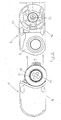
- FIG. 6 shows the alignment of the first and second side tabs 5 and 6 prior to insertion of the tongue 9 between the cheeks 8, after the rollers 32 were fitted with the ball bearings 31 on the pin 10.
- the axis of the pivot axis between the second side flap 6 and the adjacent flap 30 (FIG. FIG. 5 ) is to be seen with respect to the narrow sides 16 and 35 of the side strap strand.
- the pivot pin 26 is namely the narrow side with the tread 16 closer than the opposite narrow side 35 (a ⁇ b). This achieves that the running surfaces 16 of the adjacent side flaps do not interfere with the pivoting.
Description
Die Erfindung betrifft eine Energieführungskette nach dem Oberbegriff des Hauptanspruchs.The invention relates to an energy transmission chain according to the preamble of the main claim.
Solche Energieführungsketten sind beispielsweise aus der
Die Laufruhe der Energieführungskette kann verbessert werden, wenn man auf einer bestimmten Länge möglichst viele Kettenglieder unterbringt, d. h. die Kettenglieder möglichst kurz gestaltet. Die
Durch die Anbringung der Laufrollen an den Kettengliedern werden jedoch die Kettenglieder verlängert. Eine derartige Energieführungskette hat eine geringere Laufruhe. Wenn man nur die Kettenglieder ohne Laufrollen kürzer gestaltet als die rollentragenden Kettenglieder, ergibt sich eine ungleichmäßige Verfahrbewegung der Energieführungskette beim Ablegen und Aufnehmen sowie erhöhte Geräuschbildung.By attaching the rollers to the chain links, however, the chain links are extended. Such an energy chain has a lower smoothness. If you make only the links without rollers shorter than the roller-bearing chain links, results in a non-uniform movement of the energy chain when placing and picking up and increased noise.
Aufgabe der vorliegenden Erfindung ist es, eine Energieführungskette mit Laufrollen anzugeben, die eine hohe Laufruhe besitzt und sich gleichmäßig und mit minimaler Geräuschbildung verfahren läßt.Object of the present invention is to provide an energy guide chain with rollers, which has a high level of smoothness and can be moved evenly and with minimal noise.
Diese Aufgabe wird durch eine Energieführungskette nach dem Patentanspruch 1 gelöst.This object is achieved by a power transmission chain according to claim 1.
Zwar sind aus der
Die erfindungsgemäße Lösung ermöglicht es, dass der eine, die Gleitrolle aufweisende und mit der benachbarten Seitenlasche verschwenkbar verbindbare Abschnitt einer Seitenlasche unmittelbar an den anderen, mit der auf der anderen Seite benachbarten Seitenlasche verbindbaren Abschnitt angrenzt oder sich sogar mit diesem überschneidet. Dadurch ist es möglich, die Länge der rollentragenden Kettenglieder an die Länge der anderen Kettenglieder anzugleichen, wodurch ein gleichmäßiger Ablauf mit geringer Geräuschbildung entsteht und die Laufruhe der Kette in größeren Grenzen durch Wahl der Kettengliedlänge eingestellt werden kann. Diese Ausführungsform ist bevorzugt, obwohl die Erfindung auch mit mehr oder weniger abweichender Länge der rollentragenden Kettenglieder ausführbar ist.The solution according to the invention makes it possible for one section of the side flap, which has the sliding roller and can be connected to the adjacent side flap, to be directly adjacent to the other section which can be connected to the side flap adjacent to the other side or even intersects therewith. This makes it possible, the length of the roller-carrying chain links to the length of To match other chain links, creating a smooth flow with low noise and the smoothness of the chain can be set within limits by selecting the chain link length. This embodiment is preferred, although the invention may be practiced with more or less different lengths of roller-carrying chain links.
Bei einer erfindungsgemäßen Ausführungsform werden die Laufrollen außen an den Seitenlaschen befestigt, wobei an den Schlaufeninnenseiten der Seitenlaschen Verbreiterungen als Laufflächen für die Rollen vorgesehen sind. Dies ähnelt der in
Bevorzugt bestehen die Seitenlaschenstränge der erfindungsgemäßen Energieführungskette mehrheitlich aus untereinander gleichen Laschen, die jeweils einen (vom Kettenglied aus gesehen) nach außen und einen nach innen gekröpften Bereich aufweisen. Beim Zusammenfügen der Kette wird dann der nach innen gekröpfte Bereich der einen Lasche auf den nach außen gekröpften Bereich der nächsten Lasche gelegt und beide schwenkbar, beispielsweise durch einen in eine Aufnahme eingeführten Gelenkzapfen, miteinander verbunden. Sollen nun Seitenlaschen mit Rollen in einen solchen Strang eingegliedert werden, dann ist es vorteilhaft, auch den mit dem rollentragenden Bereich zu verbindenden Bereich der nächsten Lasche angepaßt auszugestalten, so dass sich ein rollentragendes Seitenlaschenpaar zur Eingliederung in den Seitenlaschenstrang ergibt. Die Endbereiche dieses Seitenlaschenpaars sind dann wieder so gestaltet, dass sie mit dem beispielsweise nach innen bzw. nach außen gekröpften Bereich der untereinander gleichen Laschen verbindbar sind.Preferably, the side strap strands of the energy guiding chain according to the invention consist for the most part of tabs which are identical to one another and which each have one (viewed from the chain link) to the outside and an inwardly bent region. When assembling the chain of the inwardly cranked portion of a tab is then placed on the outwardly bent portion of the next tab and both pivotally connected to each other, for example, by an inserted into a receptacle pivot pin. If now side flaps with rollers are incorporated into such a strand, then it is advantageous to customize adapted to the region of the next flap to be connected to the roller-carrying area, so that a roll-carrying side flap pair results for incorporation into the side flaps strand. The end portions of this side tab pair are then again designed so that they are bent with the example inwardly or outwardly Area of mutually identical tabs are connectable.
Demgemäß besteht ein solches Seitenlaschenpaar bevorzugt aus einer ersten Seitenlasche, die einen Bereich, der mit einer rollenlosen Seitenlasche verbindbar ist und eine Zunge, welche mindestens eine Rolle trägt, und aus einer zweiten Seitenlasche, die einen Bereich, der mit einer rollenlosen Seitenlasche verbindbar ist, und einen Führungsbereich aufweist. Dabei kann die Zunge mit dem Führungsbereich so verbunden werden, dass beide Seitenlaschen um eine mit der Achse der Rolle zusammenfallende Achse verschwenkt werden können.Accordingly, such a side flap pair preferably consists of a first side flap which has a region which is connectable to a rollless side flap and a tongue which carries at least one roll and a second side flap which has a region connectable to a rollless side flap. and a guide area. In this case, the tongue can be connected to the guide region so that both side flaps can be pivoted about an axis coincident with the axis of the roller.
Bevorzugt sind die mit den rollenlosen Seitenlaschen verbindbaren Bereiche der ersten und zweiten Seitenlasche zueinander komplementär. Dann läßt sich ein solches Seitenlaschenpaar auch in einen bestehenden Strang aus oben beschriebenen untereinander gleichen Seitenlaschen eingliedern.Preferably, the regions of the first and second side flaps which can be connected to the rollless side flaps are complementary to one another. Then, such a side tab pair can also be incorporated into an existing strand of the same side tabs described above.
Der Führungsbereich der zweiten Seitenlasche wird bevorzugt durch eine oder zwei Wangen gebildet, die sich beispielsweise in Fortsetzung der Seitenflächen der zweiten Seitenlasche erstrecken und einen Innenraum freilassen. Die Wangen können Mittel zum schwenkbaren Verbinden der Zunge mit ihnen aufnehmen. Diese Mittel können beispielsweise an der Zunge angebrachte Zapfen oder dergleichen sein. Bevorzugt sind in den Wangen kreisförmige Öffnungen vorgesehen, in die Scheiben eingelegt und an der Zunge befestigt, z. B. angeschraubt werden können. Diese Scheiben können zur weiteren Stabilisierung an der äußeren Stirnfläche einen außen auf der Wange aufliegende Flansch aufweisen.The guide region of the second side flap is preferably formed by one or two cheeks, which extend, for example, in continuation of the side surfaces of the second side flap and leave an interior space free. The cheeks may receive means for pivotally connecting the tongue with them. These means may be, for example, pins attached to the tongue or the like. Preferably, circular openings are provided in the cheeks, inserted into the discs and fixed to the tongue, for. B. can be screwed. These discs may have a flange resting on the cheek for further stabilization on the outer face.
Weiter bevorzugt wird der Führungsbereich durch zwei Wangen gebildet, zwischen die die Zunge mit der mindestens einen Rolle eingeschoben werden kann, so dass die Rolle mit einem Teil ihres Umfangsbereichs aus dem Führungsbereich herausragt.More preferably, the guide portion is formed by two cheeks, between which the tongue can be inserted with the at least one roller, so that the roller with a part its peripheral region protrudes from the guide area.
Vorteilhaft sind an beiden Seiten der Zunge Rollen angebracht. Die so gebildeten Rollenpaare begrenzen zwischen sich eine Führungsrille, die der Seitenführung des.Obertrums dient. Die Befestigung an der Zunge erfolgt dabei bevorzugt durch Aufstecken auf Zapfen an der Zunge. Besonders bevorzugt sind die Rollen kugelgelagert.Advantageously, rollers are attached to both sides of the tongue. The pairs of rollers thus formed delimit between them a guide groove, which serves the lateral guidance des.Obertrums. The attachment to the tongue is preferably carried out by plugging on pins on the tongue. Particularly preferably, the rollers are ball-bearing.
Vorteilhaft ist bei der erfindungsgemäßen Energieführungskette die Schwenkachse für benachbarte Seitenlaschen unsymmetrisch angeordnet, so dass sie näher bei der Lauffläche als bei der gegenüberliegenden Schmalseite der Seitenlaschen liegt.Advantageously, in the energy guiding chain according to the invention, the pivot axis for adjacent side flaps is arranged asymmetrically so that it lies closer to the running surface than to the opposite narrow side of the side flaps.
Die Erfindung wird nun anhand von Ausführungsbeispielen und der beigegebenen Zeichnungen näher erläutert.
-
Figur 1 zeigt ein Teilabschnitt einer erfindungsgemäßen Energieführungskette mit Obertrum und Untertrum in der Ansicht von außen auf einen Seitenlaschenstrang. -
Figur 2Figur 1 . -
Figur 3 -
Figur 4 -
Figur 5 -
Figur 6
-
FIG. 1 shows a section of a power transmission chain according to the invention with upper strand and lower strand in the view from the outside on a side strap strand. -
FIG. 2 shows the section II through the side strap strand ofFIG. 1 , -
FIG. 3 shows a first side flap of a roll-carrying side flap pair in views of six sides as well as a cross section and two perspective views. -
FIG. 4 shows a second side flap of a roll-carrying side flap pair in views of six sides and a cross section and two perspective views. -
FIG. 5 shows an exploded view of a roller-carrying side flap pair and the adjacent side bars in the strand. -
FIG. 6 shows the insertion of the first side flap into the second side flap.
In
Die Schnittdarstellung
- 11
- Untertrumstrand
- 22
- OberrtumOberrtum
- 33
- untereinander gleiche Seitenlaschenmutually identical side flaps
- 44
- SeitenlaschenpaarSide pair of tabs
- 55
- erste Seitenlaschefirst side flap
- 66
- zweite Seitenlaschesecond side flap
- 77
- Führungsbereichguide region
- 88th
- Wangecheek
- 99
- Zungetongue
- 1010
- Zapfenspigot
- 11, 1211, 12
- Laufrollencastors
- 1414
- Querstegcrosspiece
- 1515
- Scheibedisc
- 1616
- Laufflächetread
- 1717
- Zapfen für QuerstegSpigot for crosspiece
- 1818
- Aufnahme für GelenkzapfenMount for pivot pin
- 2020
- Außenflächeouter surface
- 2121
- Bohrung für SchraubeBore for screw
- 2222
- Verbindungsbereichconnecting area
- 2323
- Außenflächeouter surface
- 2424
- Öffnungopening
- 2525
- Verbindungsbereichconnecting area
- 2626
- Gelenkzapfenpivot pin
- 3030
- Seitenlascheside flap
- 3131
- Kugellagerball-bearing
- 3232
- Gleitrollecaster
- 3333
- Schraubescrew
- 3434
- Gelenkzapfenpivot pin
- 3535
- Schmalseite der SeitenlascheNarrow side of the side flap
Claims (14)
- Energy guiding chain for guiding hoses, cables and the like, with a number of chain links connected to each other in articulated fashion that are formed by mutually parallel side straps (3), connected to form parallel side strap strands, and cross-members (14) connecting them, where the side straps (3) can be pivoted relative to each other about a pivoting axis common to two adjacent side straps, where the energy guiding chain can be traversed in such a way that it forms an upper strand (2), a lower strand (1) and a deflection zone connecting the two, where the upper strand lies on the lower strand, and where rollers (11, 12) are provided on at least some chain links of the upper strand and/or the lower strand, these being arranged in such a way that they roll on running surfaces (16) provided on the chain links of the opposite strand when the energy guiding chain is traversed, characterized in that the axis of rotation of each of the rollers (11, 12) coincides with the pivoting axis of an adjacent pair (4) of side straps (5, 6).
- Energy guiding chain according to Claim 1, characterized in that the chain links provided with rollers have the same length as the rollerless chain links.
- Energy guiding chain according to Claim 1 or 2, characterized in that the rollers are mounted on the outer side of the chain links, and in that the sides of the side straps on the inside of the loop are provided with wider areas as running surfaces for the rollers.
- Energy guiding chain according to one of Claims 1 to 3, characterized in that the rollers are integrated on the inside of the side straps.
- Energy guiding chain according to one of Claims 1 to 4, characterized in that the side strap strands predominantly consist of mutually identical straps, each of which displays an inwardly cranked area and an outwardly cranked area, and in that roller-bearing side strap pairs are integrated in the strands.
- Energy guiding chain according to Claim 5, characterized in that the roller-bearing side strap pairs consist of- a first side strap displaying an area that can be connected to a rollerless side strap, and a tongue bearing at least one roller, and- a second side strap displaying an area that can be connected to a rollerless side strap, and a guide area, where the tongue can be connected to the guide area in such a way that both side straps can be pivoted about an axis coinciding with the axis of the roller.
- Energy guiding chain according to Claim 6, characterized in that the areas of the first and second side strap that can be connected to the rollerless side straps complement each other.
- Energy guiding chain according to Claim 6 or 7, characterized in that the guide area consists of one or two cheeks, which can accommodate means for connecting the tongue in pivoting fashion.
- Energy guiding chain according to Claim 8, characterized in that the tongue can be inserted between two cheeks, where the at least one roller partly projects from the guide area.
- Energy guiding chain according to one of Claims 6 to 9, characterized in that two rollers are present, being attached on both sides of the tongue.
- Energy guiding chain according to one of Claims 6 to 10, characterized in that the rollers are fitted on pins on the tongue.
- Energy guiding chain according to one of Claims 6 to 11, characterized in that the rollers are mounted in ball bearings.
- Energy guiding chain according to one of Claims 7 to 12, characterized in that the means for connecting the tongue are disks that can be inserted in a corresponding opening in the cheek and fastened on the tongue.
- Energy guiding chain according to one of the preceding Claims, characterized in that the pivoting axis for the adjacent side straps is closer to the running surface (16) than to the narrow face (35) of the side straps opposite the running surface.
Applications Claiming Priority (2)
| Application Number | Priority Date | Filing Date | Title |
|---|---|---|---|
| DE202006006645U DE202006006645U1 (en) | 2006-04-21 | 2006-04-21 | Power supply chain |
| PCT/DE2007/000677 WO2007121715A1 (en) | 2006-04-21 | 2007-04-17 | Energy conduction chain |
Publications (2)
| Publication Number | Publication Date |
|---|---|
| EP2010802A1 EP2010802A1 (en) | 2009-01-07 |
| EP2010802B1 true EP2010802B1 (en) | 2014-01-15 |
Family
ID=36710276
Family Applications (1)
| Application Number | Title | Priority Date | Filing Date |
|---|---|---|---|
| EP07722235.4A Active EP2010802B1 (en) | 2006-04-21 | 2007-04-17 | Energy conduction chain |
Country Status (8)
| Country | Link |
|---|---|
| US (1) | US7497072B2 (en) |
| EP (1) | EP2010802B1 (en) |
| JP (1) | JP4830118B2 (en) |
| KR (1) | KR101075698B1 (en) |
| CN (1) | CN101460766B (en) |
| DE (2) | DE202006006645U1 (en) |
| TW (1) | TWI314195B (en) |
| WO (1) | WO2007121715A1 (en) |
Cited By (2)
| Publication number | Priority date | Publication date | Assignee | Title |
|---|---|---|---|---|
| DE202014105940U1 (en) | 2014-12-09 | 2015-01-07 | Igus Gmbh | Reel device for at least one line and supply device with this reel device |
| WO2022123308A1 (en) | 2020-12-10 | 2022-06-16 | Igus Gmbh | Energy chains for long travels, in particular with rollers |
Families Citing this family (15)
| Publication number | Priority date | Publication date | Assignee | Title |
|---|---|---|---|---|
| DE202006006640U1 (en) * | 2006-04-21 | 2006-07-06 | Igus Gmbh | Power supply chain |
| DE202006006638U1 (en) | 2006-04-21 | 2006-06-22 | Igus Gmbh | Power supply chain |
| DE202006006645U1 (en) | 2006-04-21 | 2006-07-06 | Igus Gmbh | Power supply chain |
| KR101020761B1 (en) | 2010-10-15 | 2011-03-09 | 씨피시스템(주) | Roller assembly for cable chain |
| PL2678403T3 (en) * | 2011-02-24 | 2016-08-31 | Basf Se | Novel illumination devices |
| DE202011004762U1 (en) | 2011-04-04 | 2011-09-07 | Igus Gmbh | Power supply chain |
| DE202012003903U1 (en) * | 2012-04-19 | 2012-05-25 | Igus Gmbh | Energy guiding chain with rollers |
| DE202012003908U1 (en) * | 2012-04-19 | 2012-05-15 | Igus Gmbh | Energy guiding chain with rollers |
| US9032667B2 (en) * | 2013-07-10 | 2015-05-19 | Anthony International | Access system for a temperature controlled storage device |
| JP6262627B2 (en) * | 2014-09-24 | 2018-01-17 | 株式会社椿本チエイン | Cable protection guide device |
| US10367339B2 (en) * | 2017-05-10 | 2019-07-30 | The Boeing Company | Snag mitigating cable track apparatus |
| DE202017105644U1 (en) | 2017-09-18 | 2017-10-30 | Igus Gmbh | Energy guiding chain with rollers |
| DE202018102144U1 (en) * | 2018-04-18 | 2019-05-27 | Igus Gmbh | Energy guiding chain with damping elements and side part for it |
| DE202019107117U1 (en) | 2019-12-19 | 2021-04-19 | Igus Gmbh | Energy guiding chain and storage unit for an energy guiding chain |
| WO2023105279A1 (en) * | 2021-12-10 | 2023-06-15 | Igus Gmbh | Energy chain having plain bearing rings |
Citations (1)
| Publication number | Priority date | Publication date | Assignee | Title |
|---|---|---|---|---|
| WO2007121713A1 (en) * | 2006-04-21 | 2007-11-01 | Igus Gmbh | Energy conduction chain |
Family Cites Families (23)
| Publication number | Priority date | Publication date | Assignee | Title |
|---|---|---|---|---|
| US3284036A (en) * | 1965-05-06 | 1966-11-08 | Nat Crane Corp | Carrier link chain assembly for hoses |
| US3716986A (en) * | 1970-10-21 | 1973-02-20 | Gemco Electric Co | Rolling conductor support |
| US3779003A (en) * | 1972-09-07 | 1973-12-18 | Measurex Corp | Cable carrier with removable plastic links |
| GB1444307A (en) | 1974-10-01 | 1976-07-28 | Borjesson Kv | Chain construction |
| DE2656638A1 (en) * | 1976-12-14 | 1978-06-15 | Kurt Hennig | Flexible cover plate for power cable for machine - has curved guide to support loop formed by plates over machine tool |
| US4373324A (en) | 1980-09-02 | 1983-02-15 | Maysteel Corporation | Guide apparatus for flexible elements connected to relatively moving units |
| US4392344A (en) * | 1981-06-30 | 1983-07-12 | Central Safety Equipment Company | Chain-link cable carrier |
| JPS60125441A (en) * | 1983-12-06 | 1985-07-04 | Matsushita Electric Ind Co Ltd | Cable-dragging chain |
| DE4313075C2 (en) | 1993-04-21 | 1996-07-25 | Igus Gmbh | Energy chain |
| FR2723627B3 (en) | 1994-08-11 | 1996-07-12 | Murrplastik Systemtechnik Gmbh | GUIDANCE CHAIN FOR POWER CONDUCTORS |
| DE19512088C2 (en) * | 1995-04-03 | 1997-05-07 | Igus Gmbh | Energy chain |
| CN2261545Y (en) * | 1996-10-31 | 1997-09-03 | 威海特种电源研究所 | Cable moving apparatus |
| DE19701706C1 (en) * | 1997-01-21 | 1998-09-03 | Igus Gmbh | Energy supply chain |
| DE19715531C2 (en) | 1997-04-14 | 1999-05-27 | Igus Gmbh | Energy chain |
| US6425238B1 (en) * | 1998-05-05 | 2002-07-30 | Igus Spritzgussteile für die Industrie GmbH | Energy guiding chain |
| DE19839270C2 (en) * | 1998-05-05 | 2000-10-26 | Igus Gmbh | Energy chain |
| DE19919076C2 (en) * | 1999-04-19 | 2001-08-30 | Igus Gmbh | Energy chain |
| JP2001221293A (en) * | 2000-02-07 | 2001-08-17 | Kunimori Kagaku Co Ltd | Cable chain |
| JP4266745B2 (en) * | 2003-08-18 | 2009-05-20 | 株式会社椿本チエイン | Cable protection guide device |
| DE10343263A1 (en) | 2003-09-17 | 2005-05-04 | Murrplastik Systemtechnik Gmbh | Side unit for a link of an energy transmission chain comprises a structural element which on its surface is provided with a layer consisting of a material with a lower strength |
| DE102004022512A1 (en) | 2004-05-05 | 2005-12-01 | Kabelschlepp Gmbh | Chain link for an energy supply chain and energy supply chain with extended usage cross-section |
| FR2875065A1 (en) | 2004-09-03 | 2006-03-10 | Valeo Electronique Sys Liaison | Flat electrical conductor supporting and guiding device for motor vehicle, has chain formed with links to receive sheet, where each link has bar integrated to edge of one flange end and extending till right of related edge of another flange |
| DE202006006645U1 (en) | 2006-04-21 | 2006-07-06 | Igus Gmbh | Power supply chain |
-
2006
- 2006-04-21 DE DE202006006645U patent/DE202006006645U1/en not_active Expired - Lifetime
-
2007
- 2007-04-17 JP JP2009505716A patent/JP4830118B2/en active Active
- 2007-04-17 CN CN200780020428.0A patent/CN101460766B/en active Active
- 2007-04-17 WO PCT/DE2007/000677 patent/WO2007121715A1/en active Application Filing
- 2007-04-17 KR KR1020087028452A patent/KR101075698B1/en active IP Right Grant
- 2007-04-17 DE DE112007001536T patent/DE112007001536A5/en not_active Withdrawn
- 2007-04-17 EP EP07722235.4A patent/EP2010802B1/en active Active
- 2007-04-20 US US11/738,164 patent/US7497072B2/en active Active
- 2007-04-20 TW TW096113871A patent/TWI314195B/en active
Patent Citations (1)
| Publication number | Priority date | Publication date | Assignee | Title |
|---|---|---|---|---|
| WO2007121713A1 (en) * | 2006-04-21 | 2007-11-01 | Igus Gmbh | Energy conduction chain |
Cited By (3)
| Publication number | Priority date | Publication date | Assignee | Title |
|---|---|---|---|---|
| DE202014105940U1 (en) | 2014-12-09 | 2015-01-07 | Igus Gmbh | Reel device for at least one line and supply device with this reel device |
| WO2022123308A1 (en) | 2020-12-10 | 2022-06-16 | Igus Gmbh | Energy chains for long travels, in particular with rollers |
| DE202021004122U1 (en) | 2020-12-10 | 2022-09-15 | Igus Gmbh | Energy guiding chains for long travel distances, especially with rollers |
Also Published As
| Publication number | Publication date |
|---|---|
| DE202006006645U1 (en) | 2006-07-06 |
| DE112007001536A5 (en) | 2009-04-02 |
| TWI314195B (en) | 2009-09-01 |
| JP4830118B2 (en) | 2011-12-07 |
| KR20090014167A (en) | 2009-02-06 |
| WO2007121715A1 (en) | 2007-11-01 |
| TW200745466A (en) | 2007-12-16 |
| EP2010802A1 (en) | 2009-01-07 |
| US20070246600A1 (en) | 2007-10-25 |
| KR101075698B1 (en) | 2011-10-21 |
| CN101460766A (en) | 2009-06-17 |
| JP2009534593A (en) | 2009-09-24 |
| US7497072B2 (en) | 2009-03-03 |
| CN101460766B (en) | 2014-07-16 |
Similar Documents
| Publication | Publication Date | Title |
|---|---|---|
| EP2010802B1 (en) | Energy conduction chain | |
| EP1076784B1 (en) | Energy guiding chain | |
| DE3027834C2 (en) | Plate chain for infinitely adjustable conical pulley gear | |
| EP1359343B1 (en) | Supporting chain for energy carriers | |
| EP1108157B1 (en) | Energy guide chain for guiding lines comprising chain links which can move in three dimensions | |
| EP2010800B1 (en) | Energy conduction chain | |
| DE10345102B4 (en) | Trolley, in particular monorail cat with low height | |
| DE2914067A1 (en) | ROLLER CHAIN | |
| EP2010801B1 (en) | Energy conduction chain | |
| DE3990222B4 (en) | crawler track | |
| EP1466108A1 (en) | Energy guiding device with reduced friction forces | |
| EP2839182B1 (en) | Drag chain with rollers | |
| EP2839183A1 (en) | Cable drag chain comprising rollers | |
| EP0793784B1 (en) | Energy guiding chain with guiding stops | |
| DE4001529A1 (en) | CARRYING CHAIN, ESPECIALLY JAMED ROLLING CHAIN | |
| DE102006029530A1 (en) | Carriage for a cable drag chain | |
| DE19932636B4 (en) | pivot | |
| WO2006094423A1 (en) | Transport device, rolling body and transport body | |
| DE102007009821A1 (en) | Multi-row power transmission chain | |
| DE10137939A1 (en) | Thrust chain to be driven by sprocket has single chain links with forked ennd anr projecting element | |
| DE2209032C3 (en) | Drag chain | |
| EP1090696B2 (en) | Chain traction device for continuous drawing | |
| EP1069344B1 (en) | Side-bar chains with wear-resistant articulations | |
| EP1280973A1 (en) | Door hinge | |
| DE10109190C2 (en) | link chain |
Legal Events
| Date | Code | Title | Description |
|---|---|---|---|
| PUAI | Public reference made under article 153(3) epc to a published international application that has entered the european phase |
Free format text: ORIGINAL CODE: 0009012 |
|
| 17P | Request for examination filed |
Effective date: 20081023 |
|
| AK | Designated contracting states |
Kind code of ref document: A1 Designated state(s): AT BE BG CH CY CZ DE DK EE ES FI FR GB GR HU IE IS IT LI LT LU LV MC MT NL PL PT RO SE SI SK TR |
|
| AX | Request for extension of the european patent |
Extension state: AL BA HR MK RS |
|
| 17Q | First examination report despatched |
Effective date: 20090212 |
|
| DAX | Request for extension of the european patent (deleted) | ||
| RBV | Designated contracting states (corrected) |
Designated state(s): DE FR GB IT |
|
| GRAP | Despatch of communication of intention to grant a patent |
Free format text: ORIGINAL CODE: EPIDOSNIGR1 |
|
| INTG | Intention to grant announced |
Effective date: 20130829 |
|
| GRAS | Grant fee paid |
Free format text: ORIGINAL CODE: EPIDOSNIGR3 |
|
| GRAA | (expected) grant |
Free format text: ORIGINAL CODE: 0009210 |
|
| AK | Designated contracting states |
Kind code of ref document: B1 Designated state(s): DE FR GB IT |
|
| REG | Reference to a national code |
Ref country code: GB Ref legal event code: FG4D Free format text: NOT ENGLISH |
|
| REG | Reference to a national code |
Ref country code: DE Ref legal event code: R096 Ref document number: 502007012707 Country of ref document: DE Effective date: 20140227 |
|
| REG | Reference to a national code |
Ref country code: DE Ref legal event code: R097 Ref document number: 502007012707 Country of ref document: DE |
|
| PLBE | No opposition filed within time limit |
Free format text: ORIGINAL CODE: 0009261 |
|
| STAA | Information on the status of an ep patent application or granted ep patent |
Free format text: STATUS: NO OPPOSITION FILED WITHIN TIME LIMIT |
|
| 26N | No opposition filed |
Effective date: 20141016 |
|
| REG | Reference to a national code |
Ref country code: DE Ref legal event code: R097 Ref document number: 502007012707 Country of ref document: DE Effective date: 20141016 |
|
| REG | Reference to a national code |
Ref country code: FR Ref legal event code: PLFP Year of fee payment: 10 |
|
| REG | Reference to a national code |
Ref country code: FR Ref legal event code: PLFP Year of fee payment: 11 |
|
| REG | Reference to a national code |
Ref country code: FR Ref legal event code: PLFP Year of fee payment: 12 |
|
| P01 | Opt-out of the competence of the unified patent court (upc) registered |
Effective date: 20230526 |
|
| PGFP | Annual fee paid to national office [announced via postgrant information from national office to epo] |
Ref country code: IT Payment date: 20230428 Year of fee payment: 17 Ref country code: FR Payment date: 20230417 Year of fee payment: 17 Ref country code: DE Payment date: 20230628 Year of fee payment: 17 |
|
| PGFP | Annual fee paid to national office [announced via postgrant information from national office to epo] |
Ref country code: GB Payment date: 20230420 Year of fee payment: 17 |