EP2010123B1 - Massagegerät mit einer motorgetriebenen trommel mit frei drehbaren massageelementen - Google Patents
Massagegerät mit einer motorgetriebenen trommel mit frei drehbaren massageelementen Download PDFInfo
- Publication number
- EP2010123B1 EP2010123B1 EP07736787A EP07736787A EP2010123B1 EP 2010123 B1 EP2010123 B1 EP 2010123B1 EP 07736787 A EP07736787 A EP 07736787A EP 07736787 A EP07736787 A EP 07736787A EP 2010123 B1 EP2010123 B1 EP 2010123B1
- Authority
- EP
- European Patent Office
- Prior art keywords
- roller
- massaging members
- rotation
- massaging
- axis
- Prior art date
- Legal status (The legal status is an assumption and is not a legal conclusion. Google has not performed a legal analysis and makes no representation as to the accuracy of the status listed.)
- Active
Links
Images


Classifications
-
- A—HUMAN NECESSITIES
- A61—MEDICAL OR VETERINARY SCIENCE; HYGIENE
- A61H—PHYSICAL THERAPY APPARATUS, e.g. DEVICES FOR LOCATING OR STIMULATING REFLEX POINTS IN THE BODY; ARTIFICIAL RESPIRATION; MASSAGE; BATHING DEVICES FOR SPECIAL THERAPEUTIC OR HYGIENIC PURPOSES OR SPECIFIC PARTS OF THE BODY
- A61H15/00—Massage by means of rollers, balls, e.g. inflatable, chains, or roller chains
- A61H15/02—Massage by means of rollers, balls, e.g. inflatable, chains, or roller chains adapted for simultaneous treatment with light, heat or drugs
-
- A—HUMAN NECESSITIES
- A61—MEDICAL OR VETERINARY SCIENCE; HYGIENE
- A61H—PHYSICAL THERAPY APPARATUS, e.g. DEVICES FOR LOCATING OR STIMULATING REFLEX POINTS IN THE BODY; ARTIFICIAL RESPIRATION; MASSAGE; BATHING DEVICES FOR SPECIAL THERAPEUTIC OR HYGIENIC PURPOSES OR SPECIFIC PARTS OF THE BODY
- A61H15/00—Massage by means of rollers, balls, e.g. inflatable, chains, or roller chains
- A61H15/0078—Massage by means of rollers, balls, e.g. inflatable, chains, or roller chains power-driven
- A61H15/0085—Massage by means of rollers, balls, e.g. inflatable, chains, or roller chains power-driven hand-held
-
- A—HUMAN NECESSITIES
- A61—MEDICAL OR VETERINARY SCIENCE; HYGIENE
- A61H—PHYSICAL THERAPY APPARATUS, e.g. DEVICES FOR LOCATING OR STIMULATING REFLEX POINTS IN THE BODY; ARTIFICIAL RESPIRATION; MASSAGE; BATHING DEVICES FOR SPECIAL THERAPEUTIC OR HYGIENIC PURPOSES OR SPECIFIC PARTS OF THE BODY
- A61H15/00—Massage by means of rollers, balls, e.g. inflatable, chains, or roller chains
- A61H2015/0007—Massage by means of rollers, balls, e.g. inflatable, chains, or roller chains with balls or rollers rotating about their own axis
- A61H2015/0042—Balls or spheres
- A61H2015/005—Balls or spheres multiple on the same axis
-
- A—HUMAN NECESSITIES
- A61—MEDICAL OR VETERINARY SCIENCE; HYGIENE
- A61H—PHYSICAL THERAPY APPARATUS, e.g. DEVICES FOR LOCATING OR STIMULATING REFLEX POINTS IN THE BODY; ARTIFICIAL RESPIRATION; MASSAGE; BATHING DEVICES FOR SPECIAL THERAPEUTIC OR HYGIENIC PURPOSES OR SPECIFIC PARTS OF THE BODY
- A61H15/00—Massage by means of rollers, balls, e.g. inflatable, chains, or roller chains
- A61H2015/0064—Massage by means of rollers, balls, e.g. inflatable, chains, or roller chains with freely rotating spheres
-
- A—HUMAN NECESSITIES
- A61—MEDICAL OR VETERINARY SCIENCE; HYGIENE
- A61H—PHYSICAL THERAPY APPARATUS, e.g. DEVICES FOR LOCATING OR STIMULATING REFLEX POINTS IN THE BODY; ARTIFICIAL RESPIRATION; MASSAGE; BATHING DEVICES FOR SPECIAL THERAPEUTIC OR HYGIENIC PURPOSES OR SPECIFIC PARTS OF THE BODY
- A61H2201/00—Characteristics of apparatus not provided for in the preceding codes
- A61H2201/01—Constructive details
- A61H2201/0173—Means for preventing injuries
- A61H2201/018—By limiting the applied torque or force
-
- A—HUMAN NECESSITIES
- A61—MEDICAL OR VETERINARY SCIENCE; HYGIENE
- A61H—PHYSICAL THERAPY APPARATUS, e.g. DEVICES FOR LOCATING OR STIMULATING REFLEX POINTS IN THE BODY; ARTIFICIAL RESPIRATION; MASSAGE; BATHING DEVICES FOR SPECIAL THERAPEUTIC OR HYGIENIC PURPOSES OR SPECIFIC PARTS OF THE BODY
- A61H2201/00—Characteristics of apparatus not provided for in the preceding codes
- A61H2201/10—Characteristics of apparatus not provided for in the preceding codes with further special therapeutic means, e.g. electrotherapy, magneto therapy or radiation therapy, chromo therapy, infrared or ultraviolet therapy
- A61H2201/105—Characteristics of apparatus not provided for in the preceding codes with further special therapeutic means, e.g. electrotherapy, magneto therapy or radiation therapy, chromo therapy, infrared or ultraviolet therapy with means for delivering media, e.g. drugs or cosmetics
-
- A—HUMAN NECESSITIES
- A61—MEDICAL OR VETERINARY SCIENCE; HYGIENE
- A61H—PHYSICAL THERAPY APPARATUS, e.g. DEVICES FOR LOCATING OR STIMULATING REFLEX POINTS IN THE BODY; ARTIFICIAL RESPIRATION; MASSAGE; BATHING DEVICES FOR SPECIAL THERAPEUTIC OR HYGIENIC PURPOSES OR SPECIFIC PARTS OF THE BODY
- A61H2207/00—Anti-cellulite devices
Definitions
- the present invention generally relates to the field of machines used for massaging.
- the present invention relates to a vibrational, computerised device for treating body parts, having a draining effect on lipoedemas and lymphoedemas and a stimulation effect on the microcirculation.
- a device according to the preamble of claim 1 is known from DE 17 90 111 U .
- Machines used for applying mechanical massage are already known. Many known machines act for instance through a vacuum system allowing to suck tissues and to compress them between two cylinders which are mounted on a manual grip member applied by the operator. Such machines are obviously advantageous for treating cellulitis and muscular regions and for reactivating the blood circulation. However, notwithstanding the above advantages, these apparatuses have an application limited only to surface regions of human body tissues to be treated.
- the advantage offered by a system of this kind consists in a beneficial effect and a reduction of the time spent by the user.
- one of the objects of the present invention is to provide a device permitting to perform a treatment consisting in a method that allows to stimulate and modify both the resistance and elasticity of connective tissue, so as to re-establish a correct functional fluidity (flowability), thereby providing a profound muscle relaxation through mechanical oscillations.
- This therapy may be used as a cure for articular pain, specifically in the regions of the shoulder-nape of the neck, for treating muscle and cicatrix contractures, during massages in sport activities, for treatments before and after surgical operations; for treatments of the lymphatic system, for plantar stimulation, for the treatment of paniculus diseases with degenerative sclerotic oedema and for the re-activation of blood circulation.
- the device of the present invention has a drain effect and a stimulation effect on the microcirculation, by taking advantage of the muscles resistance and alternately squeezing the paniculus between the device itself and the muscles.
- a further object of the present invention is to allow this kind of treatment to be performed easily on all parts of the body, by employing a movable, manual grip member, which is connected to a main part of the device where an electronic control system is located.
- Another object of the present invention is to include safety systems preventing injuries to the user and failures of the electromechanical components of the device. Still another object of the present invention is to manufacture device components in such a way as to insure their maximum durability, thereby eliminating possible risks of breakage of the mechanisms used for transmitting the motion.
- the components/materials have been appropriately designed/chosen in order to extend their life and reduce friction forces during translational motion, on the epidermis, of the movable device used for applying massages.
- a further and main object of the present invention is to provide an electronic control unit, located in the main part of the device, used to control/set specific programmable functions by means of an apposite control board (panel) which is also provided on said main part of the device; consequently, the operator may choose the operation modality he/she wishes to use, as described later on.
- an object of the present invention is to generate an oscillatory action by means of the rotation of a roller around its axis, this roller supporting the round-shaped rotating components of the system, which could be spherical, cylindrical, or of any other shape, and are positioned either in a "honeycomb-like" manner or are parallel to each other; actually, the mutual arrangement of these round-shaped rotating components (massaging members) is not binding for the purposes of the present invention.
- These components give rise to a sort of "pumping effect" which promotes the elimination of surplus liquids and toxins and allows at the same time the recover of muscle tone and skin tone.
- a further object of the present invention is to permit a rotation of said roller - actuated by an electric motor - in both directions of rotation, that is clockwise and anticlockwise. This action promotes the lymphatic drainage, depending on the body regions and the kind of pathology to be treated.
- Another object of the present invention is to be able to apply this treatment also to human body regions that may have different levels of sensitivity. This is made possible by reducing or increasing the angular velocity of the roller, which implies a variation of the oscillatory (or vibrational) frequency produced by the round-shaped rotating components (massaging members) mounted on the roller itself.
- Still another object of the present invention is to protect, with an adequate protective means that also perfectly conforms to the device utilisation environment, the mobile part (hand-held member) of the device used by the operator for performing the treatment on the intended body part.
- the housing (protective means) of the device's mobile part that is, of the hand-held member, allows to easily put this device mobile part inside an apposite seat located in the device's main part, the latter receiving, as already mentioned, the electronic control unit (central unit) for the electronic control of said "roller".
- a further object of the present invention in a particular embodiment consists in performing a direct lubrication of the patient epidermis by means of the hand-held member (device mobile part) which is handled by the operator during treatment.
- This lubrication action is effected by means of a product transfer system of the analgetic product or lubricant contained within the device mobile part.
- the lubricant transfer system includes an apposite rotary tank which is in contact with the roller, and the latter, during its rotation, draws the lubricant from the tank itself by the action performed by its round-shaped rotating components and transfers the same to the epidermis by direct contact.
- a vibrational device for massaging and treating parts of the body comprising a mobile part carrying an assembly comprising separate massaging members, said assembly being in the form of a roller apt to rotate around its own rotation axis and being set in rotation by drive means formed by an electric motor coupled to a reduction gear, each of said massaging members being located around the external periphery of said roller and being freely rotatably mounted on supports, in such a manner that, due to the rotation of the roller around its own axis caused by said drive means, and due to the contact with the epidermis of said massaging members, the latter rotate on their supports, around their own geometric axis, thereby bringing about at the same time an alternate pressure action, or pumping action, exerted on the paniculus adiposus and on the underlying muscles, said drive means being mounted on said mobile part and said massaging members having a rounded shape, being for instance cylinders, oval bodies, ellipsoids, or spheres, said roller including two end
- the device of the present invention is shown in general, and schematically, in the axonometric view of Fig. 1 .
- the device includes two distinct parts, that is, a main part 1, also called “station”, and a mobile (movable) part 2, also called hand grip member or treatment member, which are connected to each other by an electric supply cable 3.
- the device is connected to the 220V electric power supply network.
- a transformer located inside the device main part 1, performs a voltage reduction to 12V, in the present example, in order to operate an electric motor 4 mounted on the mobile part 2.
- An additional transformer (not shown) is used to supply an electric voltage, in the present case 9V, to the central electronic unit, or control unit. The latter is electrically connected by means of said cable 3 to said motor 4 of the mobile part 2.
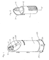
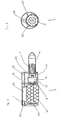
- the mobile member or part 2 comprises a handle 6, and a protective body or protective means (housing) 7, within which there is a roller 8 ( Fig. 6 ) formed by two ferrules 9, 10 located at the roller ends and carrying the massaging members, or round-shaped rotating components 11, which in the present case are spherical in shape.
- These massaging members 11 are made of a special material, which is a kind of anallergic silicone material in the preferred embodiment (claim 3).
- These through pins, or through bars 12, have the additional task of supporting the massaging members, that is, the spheres 11 (see for instance Figs. 4 and 5 ).
- a bushing 14 which facilitates the rotation of the respective sphere 11 around its own axis, by reducing friction forces between the through bar 12 and the bushing 14 itself.
- a further function of the latter is also to act as spacer for the spheres 11, one with respect to the other, so as to prevent their mutual contact and possible frictional action that would prevent their sliding/rotation.
- roller 8 of the device according to the present invention is caused by said electric motor 4 which is mounted within the handle 6 (see Fig. 3 ) and is connected to the reduction gear 15, the latter having the function to gear down the rotational (angular) velocity of the motor 4 by increasing its torque.
- a system 16 of safety friction clutches which in case of a forced blocking action exerted on the roller 8, allows a free sliding of the motor 4, thereby preventing damages and insuring a protection of the operator in case of accidental insertion of his/her fingers into the device mobile part 2.
- roller 8 also includes a small shaft or central axis 17, clamped at its ends in the respective ferrules 9, 10.
- this "roller” 8 forms a single assembly, rotating together with its through bars, or pins 12 (the latter also being clamped in the ferrules 9,10 inside the holes 13), and also rotating together with the respective spheres 11, when the central small shaft 17 is rotated by the motor 4 through the action of a connection means or power transmission hub 18 (see Fig. 3 ), the latter traversing an inner flange 19 which is also received inside the protective housing 7 of the mobile part 2.
- the mobile part 2 (see Fig. 3 ) comprises the following components: the roller 8, the safety clutch system 16, the reduction gear 15, the motor 4, the inner flange 19, which are all supported inside the outer protective housing 7 by two external discs 20, 21, the latter being in turn interconnected by means of longitudinal screws 22 in order to insure stability and to provide compactness for the above described set of components.
- the side disc 21 also has the function of receiving the handle 6 used by the operator during the handling of the movable part 2; in the preferred embodiment described herein, the other side disc 20 receives a ball bearing 23 having the task of supporting an extension of the central small shaft 17 of the roller 8 shown in Fig. 6 , thereby facilitating the rotation of this roller 8 within the protective housing 7.
- this protective means or housing 7, has an opening 24 to let part of the roller 8 project out of it, specifically its massaging members 11, in order to allow a contact with the epidermis.
- a "lubrication" of the epidermis is effected by the contact of the massaging members 11 (in this example the spheres 11) with a special rotating tank 25.
- this rotary tank 25 has a cylindrical shape and is longitudinally perforated at its centre, for the insertion of a longitudinal axis 26 which supports it during rotation.
- This rotating tank 25 is manufactured with an absorbent material, e.g. a sponge, thus allowing a gradual release of the lubricant, to improve the effectiveness of treatment.
- a plug 27 ( Fig. 9 ) closes a respective hole of the side disc 20 and allows replacement of the rotary tank 25.
- the mobile part 2 of the device is controlled by said electronic unit located inside the computerised electronic station 1 (main part 1), which allows to select the most appropriate program (regulation of the "roller” 8 velocity, control of its rotational direction and of the application time), using a control panel denoted by reference numbers 28, 28' in Fig.1 .
- the device main part 1 could be provided with small wheels 29 ( Fig. 1 ) to permit an easy displacement.
- the massaging members 2 could have a different shape and/or arrangement. It is essential, however, that a sufficient space exists between any massaging member 2 (rotating round-shaped component 2) and a neighbouring massaging member 2, to give rise to an alternating pressure on the epidermis because of the rotation of the rotating assembly 8 of massaging members 2. Furthermore, it is also essential that the massaging members 2 be mounted in the rotating assembly 8 in such a way as to be able to freely rotate around their own axis.
- the various massaging members 11, formed by the spheres 11 arranged in several rows could equally well be replaced by elongated cylinders, each of them substituting a single row of five spheres 11 of the present embodiment.
- the bushings 14 should in this case be longer and extend along the whole length of the axial through hole formed in each respective cylinder 11.
- the mobile part 2 could be directly supplied with the required electric voltage by means of batteries, without the need of an external transformer residing in the main part 1.
- the mobile part 2 could be actuated/moved by a robot in place of an operator. In that case an manipulator arm would be provided, connected with the device main part 1.
- the control action performed by the electronic unit on the motor could also take place by means of radio signals, thereby eliminating the electric cable 3, in case the mobile part 2 is supplied by internal batteries.
Landscapes
- Health & Medical Sciences (AREA)
- Rehabilitation Therapy (AREA)
- Animal Behavior & Ethology (AREA)
- Epidemiology (AREA)
- Pain & Pain Management (AREA)
- Physical Education & Sports Medicine (AREA)
- Veterinary Medicine (AREA)
- Life Sciences & Earth Sciences (AREA)
- Public Health (AREA)
- General Health & Medical Sciences (AREA)
- Bioinformatics & Cheminformatics (AREA)
- Engineering & Computer Science (AREA)
- Massaging Devices (AREA)
- Percussion Or Vibration Massage (AREA)
- Apparatuses For Bulk Treatment Of Fruits And Vegetables And Apparatuses For Preparing Feeds (AREA)
Claims (3)
- Vibrationsanordnung zum Massieren und Behandeln von Teilen des Körpers, die einen beweglichen Teil (2) aufweist, der einen Aufbau (8) trägt, der separate Massageelemente (11) aufweist, wobei der Aufbau (8) in der Form einer Walze (8) ist, die dazu geeignet ist, sich um ihre eigene Drehachse (17) zu drehen und in Drehung versetzt wird durch Antriebsmittel, die durch einen elektrischen Motor (4) ausgeformt sind, der mit einem Untersetzungsgetriebe (15) gekoppelt ist, jedes der Massageelemente (11) um den externen Umfang der Walze (8) herum angeordnet ist und frei drehbar auf Halterungen (12) befestigt ist, und zwar auf eine solche Weise, dass auf Grund der durch das Antriebsmittel bewirkten Drehung der Walze (8) um ihre eigene Achse (17) und auf Grund des Kontaktes der Epidermis mit diesen Massageelementen (11) sich die letzteren auf ihren Halterungen (12) um ihre eigene geometrische Achse drehen, wodurch sie zur gleichen Zeit eine alternierende Druckeinwirkung, oder pumpende Wirkung, bewirken, die auf den Panniculus adiposus und die darunterliegenden Muskeln ausgeübt wird,
wobei die Antriebsmittel auf dem beweglichen Teil (2) befestigt sind, und
die Massageelemente (11) eine abgerundete Form aufweisen, zum Beispiel Zylinder, ovale Körper, Ellipsoide, oder Kugeln sind,
wobei die Walze (8) zwei Metallendkappen (9, 10) aufweist, die die Enden von parallelen Durchgangsschienen oder Bolzen aufnehmen, die die Halterungen (12) ausformen, auf denen die Massageelemente (11) frei drehbar befestigt sind, wobei die Massageelemente (11) im Wesentlichen auch daran gehindert werden, sich in Längsrichtung, das heißt axial entlang der parallelen Durchgangsschienen oder Bolzen zu verschieben; dadurch gekennzeichnet, dass
ein Gehäuse (7) bereitgestellt wird, das in seinem Inneren die Walze (8) aufnimmt,
wobei das Gehäuse (7) eine Öffnung (24) aufweist um es zu ermöglichen, dass ein Teil der Walze (8), im Besonderen ein Teil der Massageelemente (11) selbst, nach außen gerichtet hervorsteht, so dass während der Drehung der Walze (8) alle diese Massageelemente (11) die zuvor genannte Pumpwirkung auf den Panniculus und die Mikrozirkulation ausüben können;
wobei weiterhin eine elektronische Steuereinheit für die Antriebsmittel zur Verfügung gestellt wird, die dazu dient, die Winkelgeschwindigkeit, die Richtung der Drehung, und die Zeitdauer der Drehung der Walze (8) zu steuern;
wobei die elektronische Einheit in einem Hauptteil (1) der Anordnung zur Verfügung gestellt wird, der eine Station ist, die auch eine Bedienkonsole (28, 28') und eine Anzeige aufweist; wobei der bewegliche Teil (2) eine Sicherheitskupplung (16) aufweist, die zwischen dem Untersetzungsgetriebe (15) und der Walze (8) und in Achse mit dem elektrischen Motor (4), dem Untersetzungsgetriebe (15) und der Walze (8) befestigt ist. - Anordnung gemäß Anspruch 1, dadurch gekennzeichnet, dass der bewegliche Teil (2) einen Behälter (25) für einen Schmierstoff aufweist, der den Schmierstoff während der Drehung der Walze (8) auf eine geregelte Weise freisetzt, wobei der Behälter (25) für den Schmierstoff eine Walze (25) aus absoxbierendem Material, zum Beispiel einem Schwamm, ausformt, die den Schmierstoff auf Grund der Reibung zwischen dem Behälter (25) und den Massageelementen (11) auf eine geregelte Weise freisetzt.
- Anordnung gemäß einem der vorherigen Ansprüche, wobei die Massageelemente (11) eine Oberfläche aufweisen, die aus anallergischem Gummi oder einer beliebigen anderen Art von ausreichend weichem Material hergestellt ist, das Vorsprünge aufweist, oder eine beliebige Art von Oberfläche und Form aufweist.
Applications Claiming Priority (2)
| Application Number | Priority Date | Filing Date | Title |
|---|---|---|---|
| IT000223A ITRM20060223A1 (it) | 2006-04-20 | 2006-04-20 | Dispositivo vibrazionale computerizzato per il trattamento delle parti del corpo |
| PCT/IT2007/000283 WO2007122656A1 (en) | 2006-04-20 | 2007-04-18 | Massaging device comprising a motor driven drum with freely rotatable massaging members |
Publications (2)
| Publication Number | Publication Date |
|---|---|
| EP2010123A1 EP2010123A1 (de) | 2009-01-07 |
| EP2010123B1 true EP2010123B1 (de) | 2010-09-01 |
Family
ID=38229753
Family Applications (1)
| Application Number | Title | Priority Date | Filing Date |
|---|---|---|---|
| EP07736787A Active EP2010123B1 (de) | 2006-04-20 | 2007-04-18 | Massagegerät mit einer motorgetriebenen trommel mit frei drehbaren massageelementen |
Country Status (6)
| Country | Link |
|---|---|
| EP (1) | EP2010123B1 (de) |
| AT (1) | ATE479415T1 (de) |
| DE (1) | DE602007008867D1 (de) |
| ES (1) | ES2351946T3 (de) |
| IT (1) | ITRM20060223A1 (de) |
| WO (1) | WO2007122656A1 (de) |
Families Citing this family (13)
| Publication number | Priority date | Publication date | Assignee | Title |
|---|---|---|---|---|
| CN101884586A (zh) * | 2010-07-05 | 2010-11-17 | 苏州工业园区博友钛钢科技有限公司 | 一种面部按摩棒 |
| CN102225035B (zh) * | 2011-05-05 | 2012-08-22 | 钟婕 | 一种滚珠按摩棒 |
| EP2810635A1 (de) * | 2013-06-03 | 2014-12-10 | Josek Berek Apolet | Sensorisches Stimulationssystem für einen Patienten mit Hirnschaden |
| ITUB20161062A1 (it) * | 2016-02-25 | 2017-08-25 | Fenix Srl | Dispositivo a microvibrazione compressiva. |
| IT201600074276A1 (it) * | 2016-07-15 | 2018-01-15 | Immacolata Isernia | Dispositivo di rotazione computerizzato per il trattamento massaggio del corpo umano |
| US11478630B2 (en) | 2017-12-18 | 2022-10-25 | Dan Sachs | Devices, systems and methods for therapeutic muscle stimulation |
| RU2704958C2 (ru) * | 2018-02-27 | 2019-10-31 | Общество с ограниченной ответственностью "Экономические Электрорешения" | Массажное устройство |
| IT201900000677A1 (it) | 2019-01-16 | 2020-07-16 | Fenix Group S R L | Dispositivo e metodo di trattamento personalizzato non-invasivo di inestetismi cutanei |
| IT201900000679A1 (it) | 2019-01-16 | 2020-07-16 | Fenix Group S R L | Dispositivo integrato per il trattamento personalizzato non-invasivo di inestetismi cutanei e metodo multifase associato |
| US20230263701A1 (en) * | 2020-07-10 | 2023-08-24 | Fenix Group S.R.L. | Device and method for the non-invasive personalized treatment of skin blemishes |
| IT202100032756A1 (it) * | 2021-12-28 | 2023-06-28 | Fenix Group S R L | Kit per il miglioramento dei disturbi associati all’infiammazione del tessuto adiposo, alle patologie flebolinfatiche e per la riabilitazione muscolare in genere |
| WO2026022794A1 (de) | 2024-09-16 | 2026-01-29 | Saxony Beauty Technology GmbH | Massageblock und massagehandgerät zur kompressiven mikrovibrationsbehandlung |
| DE102024132540A1 (de) | 2024-09-16 | 2026-03-19 | Saxony Beauty Technology GmbH | Massageblock und Massagehandgerät zur kompressiven Mikrovibrationsbehandlung |
Family Cites Families (8)
| Publication number | Priority date | Publication date | Assignee | Title |
|---|---|---|---|---|
| US1710051A (en) | 1927-03-01 | 1929-04-23 | Milo E Giacopazzi | Massaging device |
| US2003272A (en) * | 1931-01-31 | 1935-05-28 | William G Betz | Massaging device |
| CH366628A (it) | 1958-03-18 | 1963-01-15 | Pedron Mario | Apparecchio elettromassaggiatore |
| DE1141746B (de) * | 1960-11-18 | 1962-12-27 | Phil Nat Hanns Schuberth Dr Me | Kreislauf-Massagegeraet |
| FR2347035A1 (fr) * | 1976-04-09 | 1977-11-04 | Pannetier Henri | Electromasseur perfectionne pour therapeutique et amincissement |
| US4427001A (en) * | 1980-11-28 | 1984-01-24 | Mercedes Kiefer | Electrical facial massage apparatus |
| FR2714839B1 (fr) * | 1994-01-13 | 1996-03-15 | Seb Sa | Appareil délasseur pour le corps humain en particulier pour les jambes comportant un bloc de support autonome amovible. |
| US6860861B2 (en) | 2003-01-07 | 2005-03-01 | Gus Polychronis | Rotating apparatus for surface massage |
-
2006
- 2006-04-20 IT IT000223A patent/ITRM20060223A1/it unknown
-
2007
- 2007-04-18 WO PCT/IT2007/000283 patent/WO2007122656A1/en not_active Ceased
- 2007-04-18 DE DE602007008867T patent/DE602007008867D1/de active Active
- 2007-04-18 EP EP07736787A patent/EP2010123B1/de active Active
- 2007-04-18 AT AT07736787T patent/ATE479415T1/de not_active IP Right Cessation
- 2007-04-18 ES ES07736787T patent/ES2351946T3/es active Active
Also Published As
| Publication number | Publication date |
|---|---|
| DE602007008867D1 (de) | 2010-10-14 |
| WO2007122656A1 (en) | 2007-11-01 |
| ATE479415T1 (de) | 2010-09-15 |
| ES2351946T3 (es) | 2011-02-14 |
| EP2010123A1 (de) | 2009-01-07 |
| ITRM20060223A1 (it) | 2007-10-21 |
Similar Documents
| Publication | Publication Date | Title |
|---|---|---|
| EP2010123B1 (de) | Massagegerät mit einer motorgetriebenen trommel mit frei drehbaren massageelementen | |
| US6102875A (en) | Apparatus for combined application of massage, accupressure and biomagnetic therapy | |
| KR101457761B1 (ko) | 회전지압과 온열자극에 의한 복부비만 제거방법과 복부 마사지기 | |
| US20060287620A1 (en) | Power massager | |
| EP3880150B1 (de) | Handgehaltene massagevorrichtung | |
| US20250090415A1 (en) | Medical vibratory stimulation device | |
| KR100978414B1 (ko) | 마사지용 건강 지압기 | |
| WO2018100651A1 (ja) | リンパ節用マッサージ装置 | |
| RU2704958C2 (ru) | Массажное устройство | |
| KR20240001362U (ko) | 마사지용 매트 | |
| KR101288644B1 (ko) | 진동 마사지 장치 | |
| KR100948934B1 (ko) | 주무르기식 안마장치 | |
| JP2002136564A (ja) | 多機能型携帯美容機 | |
| CN208905784U (zh) | 一种揉法按摩器 | |
| KR20180023751A (ko) | 자이로스코프 세차운동 방식 피부 마사지기 | |
| CN110314075A (zh) | 一种揉法按摩器 | |
| RU2014818C1 (ru) | Физиотерапевтическое устройство для стимулирования рефлекторных точек | |
| CN106955224B (zh) | 睑板治疗仪 | |
| KR200458858Y1 (ko) | 마사지 기구 | |
| KR200458859Y1 (ko) | 2중 지압 기능이 구비된 마사지 기구 | |
| KR200230518Y1 (ko) | 자동 지압기 | |
| CN222265697U (zh) | 按摩组件、按摩机芯及按摩器 | |
| CN110478231A (zh) | 一种可深度点穴按摩头及按摩椅 | |
| EA031858B1 (ru) | Массажер электромеханический (варианты) | |
| CN209019373U (zh) | 一种用于腿部坐骨神经的护理按摩装置 |
Legal Events
| Date | Code | Title | Description |
|---|---|---|---|
| PUAI | Public reference made under article 153(3) epc to a published international application that has entered the european phase |
Free format text: ORIGINAL CODE: 0009012 |
|
| 17P | Request for examination filed |
Effective date: 20081111 |
|
| AK | Designated contracting states |
Kind code of ref document: A1 Designated state(s): AT BE BG CH CY CZ DE DK EE ES FI FR GB GR HU IE IS IT LI LT LU LV MC MT NL PL PT RO SE SI SK TR |
|
| AX | Request for extension of the european patent |
Extension state: AL BA HR MK RS |
|
| RIN1 | Information on inventor provided before grant (corrected) |
Inventor name: CAVALLETTI, ROMEO Inventor name: CAVALLETTI, GIANLUCA |
|
| GRAP | Despatch of communication of intention to grant a patent |
Free format text: ORIGINAL CODE: EPIDOSNIGR1 |
|
| DAX | Request for extension of the european patent (deleted) | ||
| RIN1 | Information on inventor provided before grant (corrected) |
Inventor name: CAVALLETTI, ROMEO Inventor name: CAVALLETTI, GIANLUCA |
|
| GRAS | Grant fee paid |
Free format text: ORIGINAL CODE: EPIDOSNIGR3 |
|
| GRAA | (expected) grant |
Free format text: ORIGINAL CODE: 0009210 |
|
| AK | Designated contracting states |
Kind code of ref document: B1 Designated state(s): AT BE BG CH CY CZ DE DK EE ES FI FR GB GR HU IE IS IT LI LT LU LV MC MT NL PL PT RO SE SI SK TR |
|
| REG | Reference to a national code |
Ref country code: GB Ref legal event code: FG4D |
|
| REG | Reference to a national code |
Ref country code: CH Ref legal event code: EP |
|
| REG | Reference to a national code |
Ref country code: IE Ref legal event code: FG4D |
|
| REF | Corresponds to: |
Ref document number: 602007008867 Country of ref document: DE Date of ref document: 20101014 Kind code of ref document: P |
|
| REG | Reference to a national code |
Ref country code: CH Ref legal event code: NV Representative=s name: FIAMMENGHI-FIAMMENGHI |
|
| REG | Reference to a national code |
Ref country code: NL Ref legal event code: VDEP Effective date: 20100901 |
|
| PG25 | Lapsed in a contracting state [announced via postgrant information from national office to epo] |
Ref country code: FI Free format text: LAPSE BECAUSE OF FAILURE TO SUBMIT A TRANSLATION OF THE DESCRIPTION OR TO PAY THE FEE WITHIN THE PRESCRIBED TIME-LIMIT Effective date: 20100901 Ref country code: LT Free format text: LAPSE BECAUSE OF FAILURE TO SUBMIT A TRANSLATION OF THE DESCRIPTION OR TO PAY THE FEE WITHIN THE PRESCRIBED TIME-LIMIT Effective date: 20100901 Ref country code: AT Free format text: LAPSE BECAUSE OF FAILURE TO SUBMIT A TRANSLATION OF THE DESCRIPTION OR TO PAY THE FEE WITHIN THE PRESCRIBED TIME-LIMIT Effective date: 20100901 |
|
| REG | Reference to a national code |
Ref country code: ES Ref legal event code: FG2A Effective date: 20110202 |
|
| LTIE | Lt: invalidation of european patent or patent extension |
Effective date: 20100901 |
|
| PG25 | Lapsed in a contracting state [announced via postgrant information from national office to epo] |
Ref country code: CY Free format text: LAPSE BECAUSE OF FAILURE TO SUBMIT A TRANSLATION OF THE DESCRIPTION OR TO PAY THE FEE WITHIN THE PRESCRIBED TIME-LIMIT Effective date: 20100901 Ref country code: SI Free format text: LAPSE BECAUSE OF FAILURE TO SUBMIT A TRANSLATION OF THE DESCRIPTION OR TO PAY THE FEE WITHIN THE PRESCRIBED TIME-LIMIT Effective date: 20100901 Ref country code: PL Free format text: LAPSE BECAUSE OF FAILURE TO SUBMIT A TRANSLATION OF THE DESCRIPTION OR TO PAY THE FEE WITHIN THE PRESCRIBED TIME-LIMIT Effective date: 20100901 |
|
| PG25 | Lapsed in a contracting state [announced via postgrant information from national office to epo] |
Ref country code: SE Free format text: LAPSE BECAUSE OF FAILURE TO SUBMIT A TRANSLATION OF THE DESCRIPTION OR TO PAY THE FEE WITHIN THE PRESCRIBED TIME-LIMIT Effective date: 20100901 Ref country code: LV Free format text: LAPSE BECAUSE OF FAILURE TO SUBMIT A TRANSLATION OF THE DESCRIPTION OR TO PAY THE FEE WITHIN THE PRESCRIBED TIME-LIMIT Effective date: 20100901 Ref country code: GR Free format text: LAPSE BECAUSE OF FAILURE TO SUBMIT A TRANSLATION OF THE DESCRIPTION OR TO PAY THE FEE WITHIN THE PRESCRIBED TIME-LIMIT Effective date: 20101202 Ref country code: NL Free format text: LAPSE BECAUSE OF FAILURE TO SUBMIT A TRANSLATION OF THE DESCRIPTION OR TO PAY THE FEE WITHIN THE PRESCRIBED TIME-LIMIT Effective date: 20100901 |
|
| PG25 | Lapsed in a contracting state [announced via postgrant information from national office to epo] |
Ref country code: EE Free format text: LAPSE BECAUSE OF FAILURE TO SUBMIT A TRANSLATION OF THE DESCRIPTION OR TO PAY THE FEE WITHIN THE PRESCRIBED TIME-LIMIT Effective date: 20100901 Ref country code: PT Free format text: LAPSE BECAUSE OF FAILURE TO SUBMIT A TRANSLATION OF THE DESCRIPTION OR TO PAY THE FEE WITHIN THE PRESCRIBED TIME-LIMIT Effective date: 20110103 Ref country code: SK Free format text: LAPSE BECAUSE OF FAILURE TO SUBMIT A TRANSLATION OF THE DESCRIPTION OR TO PAY THE FEE WITHIN THE PRESCRIBED TIME-LIMIT Effective date: 20100901 Ref country code: IS Free format text: LAPSE BECAUSE OF FAILURE TO SUBMIT A TRANSLATION OF THE DESCRIPTION OR TO PAY THE FEE WITHIN THE PRESCRIBED TIME-LIMIT Effective date: 20110101 Ref country code: CZ Free format text: LAPSE BECAUSE OF FAILURE TO SUBMIT A TRANSLATION OF THE DESCRIPTION OR TO PAY THE FEE WITHIN THE PRESCRIBED TIME-LIMIT Effective date: 20100901 Ref country code: RO Free format text: LAPSE BECAUSE OF FAILURE TO SUBMIT A TRANSLATION OF THE DESCRIPTION OR TO PAY THE FEE WITHIN THE PRESCRIBED TIME-LIMIT Effective date: 20100901 |
|
| PG25 | Lapsed in a contracting state [announced via postgrant information from national office to epo] |
Ref country code: BE Free format text: LAPSE BECAUSE OF FAILURE TO SUBMIT A TRANSLATION OF THE DESCRIPTION OR TO PAY THE FEE WITHIN THE PRESCRIBED TIME-LIMIT Effective date: 20100901 |
|
| PLBE | No opposition filed within time limit |
Free format text: ORIGINAL CODE: 0009261 |
|
| STAA | Information on the status of an ep patent application or granted ep patent |
Free format text: STATUS: NO OPPOSITION FILED WITHIN TIME LIMIT |
|
| PGFP | Annual fee paid to national office [announced via postgrant information from national office to epo] |
Ref country code: CH Payment date: 20110428 Year of fee payment: 5 |
|
| 26N | No opposition filed |
Effective date: 20110606 |
|
| PG25 | Lapsed in a contracting state [announced via postgrant information from national office to epo] |
Ref country code: DK Free format text: LAPSE BECAUSE OF FAILURE TO SUBMIT A TRANSLATION OF THE DESCRIPTION OR TO PAY THE FEE WITHIN THE PRESCRIBED TIME-LIMIT Effective date: 20100901 |
|
| PGFP | Annual fee paid to national office [announced via postgrant information from national office to epo] |
Ref country code: GB Payment date: 20110419 Year of fee payment: 5 |
|
| PGFP | Annual fee paid to national office [announced via postgrant information from national office to epo] |
Ref country code: DE Payment date: 20110525 Year of fee payment: 5 |
|
| REG | Reference to a national code |
Ref country code: DE Ref legal event code: R097 Ref document number: 602007008867 Country of ref document: DE Effective date: 20110606 |
|
| PG25 | Lapsed in a contracting state [announced via postgrant information from national office to epo] |
Ref country code: MC Free format text: LAPSE BECAUSE OF NON-PAYMENT OF DUE FEES Effective date: 20110430 |
|
| PG25 | Lapsed in a contracting state [announced via postgrant information from national office to epo] |
Ref country code: MT Free format text: LAPSE BECAUSE OF FAILURE TO SUBMIT A TRANSLATION OF THE DESCRIPTION OR TO PAY THE FEE WITHIN THE PRESCRIBED TIME-LIMIT Effective date: 20100901 |
|
| REG | Reference to a national code |
Ref country code: IE Ref legal event code: MM4A |
|
| PG25 | Lapsed in a contracting state [announced via postgrant information from national office to epo] |
Ref country code: IE Free format text: LAPSE BECAUSE OF NON-PAYMENT OF DUE FEES Effective date: 20110418 |
|
| REG | Reference to a national code |
Ref country code: CH Ref legal event code: PL |
|
| GBPC | Gb: european patent ceased through non-payment of renewal fee |
Effective date: 20120418 |
|
| PG25 | Lapsed in a contracting state [announced via postgrant information from national office to epo] |
Ref country code: GB Free format text: LAPSE BECAUSE OF NON-PAYMENT OF DUE FEES Effective date: 20120418 Ref country code: LI Free format text: LAPSE BECAUSE OF NON-PAYMENT OF DUE FEES Effective date: 20120430 Ref country code: CH Free format text: LAPSE BECAUSE OF NON-PAYMENT OF DUE FEES Effective date: 20120430 |
|
| REG | Reference to a national code |
Ref country code: DE Ref legal event code: R119 Ref document number: 602007008867 Country of ref document: DE Effective date: 20121101 |
|
| PG25 | Lapsed in a contracting state [announced via postgrant information from national office to epo] |
Ref country code: LU Free format text: LAPSE BECAUSE OF NON-PAYMENT OF DUE FEES Effective date: 20110418 |
|
| PG25 | Lapsed in a contracting state [announced via postgrant information from national office to epo] |
Ref country code: TR Free format text: LAPSE BECAUSE OF FAILURE TO SUBMIT A TRANSLATION OF THE DESCRIPTION OR TO PAY THE FEE WITHIN THE PRESCRIBED TIME-LIMIT Effective date: 20100901 Ref country code: BG Free format text: LAPSE BECAUSE OF FAILURE TO SUBMIT A TRANSLATION OF THE DESCRIPTION OR TO PAY THE FEE WITHIN THE PRESCRIBED TIME-LIMIT Effective date: 20101201 |
|
| PG25 | Lapsed in a contracting state [announced via postgrant information from national office to epo] |
Ref country code: HU Free format text: LAPSE BECAUSE OF FAILURE TO SUBMIT A TRANSLATION OF THE DESCRIPTION OR TO PAY THE FEE WITHIN THE PRESCRIBED TIME-LIMIT Effective date: 20100901 |
|
| PG25 | Lapsed in a contracting state [announced via postgrant information from national office to epo] |
Ref country code: DE Free format text: LAPSE BECAUSE OF NON-PAYMENT OF DUE FEES Effective date: 20121101 |
|
| REG | Reference to a national code |
Ref country code: FR Ref legal event code: PLFP Year of fee payment: 9 |
|
| REG | Reference to a national code |
Ref country code: FR Ref legal event code: PLFP Year of fee payment: 10 |
|
| REG | Reference to a national code |
Ref country code: FR Ref legal event code: PLFP Year of fee payment: 11 |
|
| REG | Reference to a national code |
Ref country code: ES Ref legal event code: PC2A Owner name: FENIX S.R.L. Effective date: 20180306 |
|
| REG | Reference to a national code |
Ref country code: FR Ref legal event code: PLFP Year of fee payment: 12 |
|
| REG | Reference to a national code |
Ref country code: FR Ref legal event code: CD Owner name: FENIX S.R.L., IT Effective date: 20180406 |
|
| REG | Reference to a national code |
Ref country code: ES Ref legal event code: PC2A Owner name: FENIX GROUP S.R.L. Effective date: 20220830 |
|
| PGFP | Annual fee paid to national office [announced via postgrant information from national office to epo] |
Ref country code: ES Payment date: 20250529 Year of fee payment: 19 |
|
| PGFP | Annual fee paid to national office [announced via postgrant information from national office to epo] |
Ref country code: IT Payment date: 20250424 Year of fee payment: 19 |
|
| PGFP | Annual fee paid to national office [announced via postgrant information from national office to epo] |
Ref country code: FR Payment date: 20250424 Year of fee payment: 19 |