EP2009662A1 - Multi-way rocker switch - Google Patents
Multi-way rocker switch Download PDFInfo
- Publication number
- EP2009662A1 EP2009662A1 EP07012382A EP07012382A EP2009662A1 EP 2009662 A1 EP2009662 A1 EP 2009662A1 EP 07012382 A EP07012382 A EP 07012382A EP 07012382 A EP07012382 A EP 07012382A EP 2009662 A1 EP2009662 A1 EP 2009662A1
- Authority
- EP
- European Patent Office
- Prior art keywords
- tilting
- hinge
- toggle switch
- hinge plate
- axes
- Prior art date
- Legal status (The legal status is an assumption and is not a legal conclusion. Google has not performed a legal analysis and makes no representation as to the accuracy of the status listed.)
- Granted
Links
Images


Classifications
-
- H—ELECTRICITY
- H01—ELECTRIC ELEMENTS
- H01H—ELECTRIC SWITCHES; RELAYS; SELECTORS; EMERGENCY PROTECTIVE DEVICES
- H01H25/00—Switches with compound movement of handle or other operating part
- H01H25/04—Operating part movable angularly in more than one plane, e.g. joystick
- H01H25/041—Operating part movable angularly in more than one plane, e.g. joystick having a generally flat operating member depressible at different locations to operate different controls
-
- G—PHYSICS
- G06—COMPUTING; CALCULATING OR COUNTING
- G06F—ELECTRIC DIGITAL DATA PROCESSING
- G06F3/00—Input arrangements for transferring data to be processed into a form capable of being handled by the computer; Output arrangements for transferring data from processing unit to output unit, e.g. interface arrangements
- G06F3/01—Input arrangements or combined input and output arrangements for interaction between user and computer
- G06F3/03—Arrangements for converting the position or the displacement of a member into a coded form
- G06F3/033—Pointing devices displaced or positioned by the user, e.g. mice, trackballs, pens or joysticks; Accessories therefor
- G06F3/0338—Pointing devices displaced or positioned by the user, e.g. mice, trackballs, pens or joysticks; Accessories therefor with detection of limited linear or angular displacement of an operating part of the device from a neutral position, e.g. isotonic or isometric joysticks
-
- H—ELECTRICITY
- H01—ELECTRIC ELEMENTS
- H01H—ELECTRIC SWITCHES; RELAYS; SELECTORS; EMERGENCY PROTECTIVE DEVICES
- H01H25/00—Switches with compound movement of handle or other operating part
- H01H25/04—Operating part movable angularly in more than one plane, e.g. joystick
- H01H25/041—Operating part movable angularly in more than one plane, e.g. joystick having a generally flat operating member depressible at different locations to operate different controls
- H01H2025/046—Operating part movable angularly in more than one plane, e.g. joystick having a generally flat operating member depressible at different locations to operate different controls having a spherical bearing between operating member and housing or bezel
Definitions
- the present invention relates to a multiway toggle switch according to the preamble of claim 1.
- Such reusable toggle switches are used in a wide variety of electronic devices such as mobile phones, PDAs, (car) radios or navigation systems in order to operate individual functions of the respective device or to be able to navigate through its user interface.
- electronic devices such as mobile phones, PDAs, (car) radios or navigation systems
- many such multi-way toggle switches are not discrete, which means that multiple or even all sides of the switch can be simultaneously undesirably actuated, which may result in multiple movable contacts simultaneously contacting their associated stationary contacts.
- this toggle switch is subject to wear caused by the fact that each time the toggle switch its toggle key comes into frictional contact with said projections, whereby the projections are worn over time, so that an unwanted Mehrfachrome ist in this toggle switch not permanently excluded can be.
- the invention has for its object to further develop a reusable toggle switch according to the preamble of claim 1 that an unwanted Mehrfachrome ist can be permanently excluded.
- the reusable toggle switch comprises a hinge plate with a plurality of intersecting and parallel to the tilt axes of the tilting hinge hinge axes around which deforms the hinge plate at a tilt of the tilt button for transmitting the tilting movement of the tilt button on the movable contacts ,
- the hinge plate In the case of a tilting of the tilting key about a first tilting axis, the hinge plate thereby deforms about an associated first hinge axis such that it blocks a simultaneous tilting of the tilting key about a second tilting axis crossing the first tilting axis.
- the invention is based on the finding that when the hinge plate was deliberately deformed by tilting the tilting key about a first tilting axis about an associated first hinge axis, it is then impossible to simultaneously tilt the tilting key about a second tilting axis crossing the first tilting axis such tilting is prevented by the hinge plate deformed about the first hinge axis.
- the intersecting hinge axes mutually subdivided into a plurality of hinge axis sections, so that the hinge axis sections of the hinge axis crossing the first hinge axis intersect when the hinge plate was deformed at the tilting of the tilting button about the first tilting axis about the associated first hinge axis.
- the hinge axis sections of the hinge axes crossing the first hinge axis intersect, it is impossible to deform the hinge plate about these hinge axis sections, which reliably counteracts unwanted multiple contacting of the multiway toggle switch.
- the multi-way toggle switch according to the invention may be formed as a four-way toggle switch, which means that the circuit board has four diamond-shaped arranged, in particular the vertices of a square defining stationary contacts. In a corresponding manner, four movable contacts are present in this case, which are also arranged diamond-shaped or square.
- the hinge plate has at least two mutually perpendicular hinge axes, so that the tilt button in a corresponding manner to two tilting axes perpendicular to each other can be tilted.
- the tilting and hinge axes run parallel to the diagonals of said diamonds or squares, so that when the tilting key is tilted about a tilting axis, targeted contacting of those contacts is achieved which lie on the respective other diagonal.
- the hinge plate has only two perpendicular crossing hinge axes, however, it may prove advantageous to form the hinge plate with four hinge axes, which are oriented so that the hinge plate is divided into nine areas.
- the hinge plate has two pairs of parallel hinge axes, with one pair crossing the other pair vertically. In this way, the hinge plate is divided into three times three, so nine areas.
- This embodiment proves to be advantageous in that thereby the area lying in the middle of the three times three areas can be used for fastening purposes of the hinge plate, since in this case only the eight edge areas are subjected to a deformation.
- the hinge plate can be made in one piece from a permanently elastic plastic material, wherein the hinge axes are formed by film hinges, which flexibly and movably the adjacent areas of the hinge plate connect.
- the hinge plate is thus designed as a single, one-piece part, which can be produced inexpensively, for example by means of an injection molding process. Because of the hinge plate is made of a durable elastic material, there is no mechanical wear along the hinge axes formed by the film hinges, which the risk of Mehrfachrome réelle can be permanently excluded with the reusable toggle switch according to the invention.
- the hinge plate can also be made of a permanently elastic metal, in particular spring steel, in which the hinge axes are impressed.
- the multi-way toggle switch may further comprise a holding body attached to the circuit board to which the hinge plate is attached.
- the tilt button can be mounted on the holding body, for example via a ball joint.
- the toggle button of the multi-way toggle switch can be provided with markings indicating the desired tilting directions of the switch, it is undesirable for the tilt button to be twisted, as the marks would then be pointing in wrong directions.
- the holding body and the tilting key can have mutually coordinated engagement sections in such a manner that they engage with each other, but at the same time allow tilting of the tilting button about its tilting axes.
- the holding body can be composed of an upper part and a lower part, wherein the hinge plate is arranged between the two parts.
- the unit of holding body and hinge plate can thereby already before the actual assembly of the reusable toggle switch be pre-assembled, whereby the actual assembly of the reusable toggle switch can be performed time-saving.
- the hinge plate is preferably received by the latter and thus the deformation of the hinge plate can not be transferred directly to the movable contacts, the individual contacts associated transmission elements are further provided which the deformation of the hinge plate due to tilting of the tilt button transmit the moving contacts.
- the holding body may have a plurality of guides, in particular four guides, which each receive a transmission element slidably.
- the transmission elements are in contact with the underside of the hinge plate, so that caused by a tilting of the tilting button deformation of the hinge plate is transmitted to an associated movable contact.
- the transmission elements may have openings which are aligned with corresponding openings in the holder body and in the hinge plate. In this way, the tilting button can be backlit by means of at least one light source arranged on the printed circuit board, without having to equip the tilting key itself with corresponding lighting means.
- the individual transmission elements can be connected to each other via elastic spring arms, which, for example, a spiral Shape to wind at least partially around the transmission elements around.
- elastic spring arms By connecting the transmission elements via said spring arms, the transmission elements can be mounted faster because not every transmission element must be installed individually.
- the spring arms do not obstruct the displaceability of the transmission elements, since they are made on the one hand as the transmission elements of a resilient plastic material and on the other hand their elasticity is supported by the spiral shape.
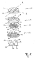
- the illustrated multi-way toggle switch 10 has, viewed from top to bottom, a circular tilting key 12, a housing 42 with a circular opening for receiving the tilting key 12, an upper holding body portion 14, a hinge plate 20, a lower one Holding body part 16, four connected by spring arms 40a, 40b, 40c, 40d transmission elements 18a, 18b, 18c, 18d, an elastic switching mat 26 and a circuit board 22 on.
- the printed circuit board 22 has four stationary contacts 24a, 24b, 24c, 24d, which are arranged at a uniform angular distance of about 90 ° around a point corresponding to the center of the tilting key 12.
- four upwardly open, elastic elevations 28a, 28b, 28c, 28d are formed on the elastic switching mat 26, which comprise on the inside of their upper end surfaces not shown movable, circular contact elements which the stationary contacts 24a, 24b, 24c , 24d of the circuit board 22 each spaced from each other.
- the elastic elevations 28a, 28b, 28c, 28d are reversibly deformable in the vertical direction and designed such that they buckle when a predetermined compressive force is exceeded in order to generate a perceptible for an operator shift feel.
- the tilting button 12 In order to apply the required compressive force for buckling of the transmission elements 18a, 18b, 18c, 18d and for closing the contacts 24a, 24b, 24c, 24d, the tilting button 12, which protrudes from the circular opening of the housing 42 partially to one of Operator to be pressed. How the particular Fig. 3 can be removed, the toggle button 12 is pivotally mounted via a ball joint 36 on the upper holding body part 14, which in turn with a plurality of pins 32 (FIG. Fig. 2 ) on the printed circuit board 22 (FIG. Fig. 1 ) is attached. The pins 32 protrude through corresponding openings in the lower Holding body 16 therethrough, which in turn has an upstanding spherical body for producing said articulated connection 36 with the tilting key 12.
- the lower holding part 16 further has four tubular guide openings 38a, 38b, 38c, 38d, which are arranged at a uniform angular distance of approximately 90 ° about a point corresponding to the center of the tilting button 12 around.
- the guide openings 38a, 38b, 38c, 38d receive the transmission elements 18a, 18b, 18c, 18d so that they are slidably mounted in the guide openings 38a, 38b, 38c, 38d in order to exert a compressive force on the tilting button 12 by tilting Transmission elements 18a, 18b, 18c, 18d to be able to apply to the elevations 28a, 28b, 28c, 28d.
- the Mehrwegkippschalter 10 therefore has the hinge plate 20, which has two pairs of parallel hinge axes a 1 , a 2 , b 1 , b 2 , wherein the one Pair a 1 , a 2 the other pair b 1 , b 2 crosses vertically.
- the hinge axes a 1 , a 2 of the hinge plate 20 extend parallel to the tilt axis A of the tilting button 12 and the hinge axes b 1 , b 2 extend in a corresponding manner parallel to the tilt axis B of the tilting key 12.
- the hinge axes a 1 , a 2 , b 1 , b 2 the hinge plate 20 is divided into three times three, so nine areas.
- the hinge plate 20 can be, for example, an approximately circular disk made of an elastic plastic material, in which the hinge axes a 1 , a 2 , b 1 , b 2 are formed by film hinges. However, it would also be possible to manufacture the hinge plate 20 from a spring steel and to impress the hinge axes a 1 , a 2 , b 1 , b 2 therein.
- the hinge plate 20 To attach the hinge plate 20 to the lower support body part 16, the hinge plate 20 has an opening 30 in the middle to be received by a corresponding circular seat 44 on the lower support body part 16.
- the hinge plate 20 serves, for example, in the event of a tilting of the tilting key 12 about the tilting axis B, a simultaneous tilting of the tilting key 12 about the tilting axis A is blocked. This is due to the fact that with a tilting of the tilting button 12 about the tilt axis B, the hinge plate 20 is deformed about the hinge axis b1 so that it can not be bent simultaneously about one of the hinge axes a 1 , a 2 .
- the tilt button 12 is tilted about the axis B, as shown in the Fig. 2 and 3 is shown, this results in that the three adjacent to the hinge axis b1 edge regions of the hinge plate 20 are bent down or tilted.
- the transmission element 18d is displaced translationally downward at the same time, so that ultimately the projection 28d buckles, resulting in a contacting of the stationary contact 24d on the circuit board 22.
- the tilting button 12 Since a direct contact of the middle edge regions of the hinge plate 20 is prevented by the tilting button 12 by the upstanding projections 46 on the upper side of the upper holding body part 14, the tilting button 12 has a downwardly directed cylinder wall 52 and the middle edge regions of the tilting button 12 are with radially projecting actuating projections 50a, 50b, 50c, 50d, which extend between the projections 46 in the radial direction further than the projections 46 to the outside.
- the cylinder wall 52 of the tilting key 12 does not collide with the projections 46 but rather comes into abutment with one of the actuating projections 50a, 50b, 50c, 50d, whereby the desired deformation of the hinge plate 20 can be caused.
- the multi-way toggle switch 10 is designed such that defined light passageways between those on the Printed circuit board 22 located light sources (not shown) and the tilting button 12 are generated.
- elevations 28a, 28b, 28c, 28d are provided at its upper end surface in the same manner as the central edge regions of the hinge plate 20 with openings 34a, 34b, 34d, so that light rays from which on the circuit board 22nd light sources are transmitted, can pass through the elevations 28a, 28b, 28c, 28d and the tubular transmission elements 18a, 18b, 18c, 18d and the hinge plate 20 up to the tilt button 12 to backlight their tilting marks (not shown).
- the hinge plate 20 is disposed between the tilting key 12 and the transmission members 18a, 18b, 18c, 18d. In fact, however, the positioning of the hinge plate 20 is not critical. In principle, the hinge plate 20 can namely be arranged at any point in the path of action between the tilting key 12 and the contacts of the multiway toggle switch 10, such as between the transmission elements 18a, 18b, 18c, 18d and the elastic switching mat 26.
- the multi-way toggle switch 10 shown in the figures instead of a hinge plate 20, which two pairs of vertically crossing hinge axes a 1 , a 2 ; b 1 , b 2 , may also be equipped with a hinge plate, which has only two vertically intersecting hinge axes.
- the hinge plate would be divided into four equal areas, the hinge axes are equally parallel to the tilt axes A, B of the tilting button 12 and interrupted by the openings 34a, 34b, 34c, 34d.
Abstract
Description
Die vorliegende Erfindung betrifft einen Mehrweg-Kippschalter gemäß dem Oberbegriff des Anspruchs 1.The present invention relates to a multiway toggle switch according to the preamble of claim 1.
Derartige Mehrweg-Kippschalter kommen in unterschiedlichsten elektronischen Geräten wie beispielsweise Mobiltelefonen, PDAs, (Auto-)Radios oder Navigationssystemen zum Einsatz, um damit einzelne Funktionen des jeweiligen Geräts bedienen oder durch dessen Benutzeroberfläche navigieren zu können. Viele derartiger Mehrweg-Kippschalter sind jedoch nicht diskret, was bedeutet, dass mehrere oder sogar alle Seiten des Schalters gleichzeitig in unerwünschter Weise betätigt werden können, was dazu führen kann, dass gleichzeitig mehrere bewegliche Kontakte die ihnen zugeordneten stationären Kontakte kontaktieren.Such reusable toggle switches are used in a wide variety of electronic devices such as mobile phones, PDAs, (car) radios or navigation systems in order to operate individual functions of the respective device or to be able to navigate through its user interface. However, many such multi-way toggle switches are not discrete, which means that multiple or even all sides of the switch can be simultaneously undesirably actuated, which may result in multiple movable contacts simultaneously contacting their associated stationary contacts.
Um einer derartigen Mehrfachkontaktierung entgegenzuwirken, wird in der
Darüber hinaus ist dieser Kippschalter mit Verschleißerscheinungen behaftet, welche dadurch entstehen, dass bei jeder Betätigung des Kippschalters dessen Kipptaste mit den genannten Vorsprünge in Reibkontakt gelangt, wodurch die Vorsprünge mit der Zeit abgenützt werden, so dass eine unerwünschte Mehrfachkontaktierung bei diesem Kippschalter auf Dauer nicht ausgeschlossen werden kann.In addition, this toggle switch is subject to wear caused by the fact that each time the toggle switch its toggle key comes into frictional contact with said projections, whereby the projections are worn over time, so that an unwanted Mehrfachkontaktierung in this toggle switch not permanently excluded can be.
Der Erfindung liegt die Aufgabe zugrunde, einen Mehrweg-Kippschalter gemäß dem Oberbegriff des Anspruchs 1 dahingehend weiterzuentwickeln, dass eine unerwünschte Mehrfachkontaktierung dauerhaft ausgeschlossen werden kann.The invention has for its object to further develop a reusable toggle switch according to the preamble of claim 1 that an unwanted Mehrfachkontaktierung can be permanently excluded.
Diese Aufgabe wird mit einem Mehrweg-Kippschalter gelöst, welcher die Merkmale des Anspruchs 1 aufweist. Insbesondere wird die Aufgabe dadurch gelöst, dass der Mehrweg-Kippschalter eine Scharnierplatte mit mehreren sich kreuzenden und parallel zu den Kippachsen der Kipptaste verlaufenden Scharnierachsen umfasst, um die sich die Scharnierplatte bei einer Verkippung der Kipptaste zur Übertragung der Kippbewegung der Kipptaste auf die beweglichen Kontakte verformt. Bei einer Verkippung der Kipptaste um eine erste Kippachse verformt sich dabei die Scharnierplatte derart um eine zugehörige erste Scharnierachse, dass sie eine gleichzeitige Verkippung der Kipptaste um eine die erste Kippachse kreuzende zweite Kippachse sperrt.This object is achieved with a multi-way toggle switch, which has the features of claim 1. In particular, the object is achieved in that the reusable toggle switch comprises a hinge plate with a plurality of intersecting and parallel to the tilt axes of the tilting hinge hinge axes around which deforms the hinge plate at a tilt of the tilt button for transmitting the tilting movement of the tilt button on the movable contacts , In the case of a tilting of the tilting key about a first tilting axis, the hinge plate thereby deforms about an associated first hinge axis such that it blocks a simultaneous tilting of the tilting key about a second tilting axis crossing the first tilting axis.
Mit anderen Worten wird dadurch, dass sich die Scharnierplatte um die erste Scharnierachse verformt, eine die erste Scharnierachse kreuzende zweite Scharnierachse derart verformt, dass sich die Scharnierplatte nicht mehr um diese zweite Scharnierachse verbiegen lässt. Dies macht es unmöglich, die Kipptaste um eine parallel zu der zweiten Scharnierachse verlaufende zweite Kippachse zu verkippen.In other words, as a result of the hinge plate deforming about the first hinge axis, a second hinge axis crossing the first hinge axis is deformed in such a way that the hinge plate can no longer bend about this second hinge axis. This makes it impossible to tilt the toggle button about a second tilt axis parallel to the second hinge axis.
Der Erfindung liegt dabei die Erkenntnis zugrunde, dass, wenn die Scharnierplatte durch Verkippung der Kipptaste um eine erste Kippachse um eine zugehörige erste Scharnierachse gezielt verformt wurde, es dann unmöglich ist, die Kipptaste gleichzeitig um eine die erste Kippachse kreuzende zweite Kippachse zu verkippen, da eine derartige Verkippung durch die um die erste Scharnierachse verformte Scharnierplatte verhindert wird.The invention is based on the finding that when the hinge plate was deliberately deformed by tilting the tilting key about a first tilting axis about an associated first hinge axis, it is then impossible to simultaneously tilt the tilting key about a second tilting axis crossing the first tilting axis such tilting is prevented by the hinge plate deformed about the first hinge axis.
So unterteilen sich nämlich die sich kreuzenden Scharnierachsen gegenseitig in mehrere Scharnierachsenabschnitte, so dass sich die Scharnierachsenabschnitte der die erste Scharnierachse kreuzenden Scharnierachsen schneiden, wenn die Scharnierplatte bei der Verkippung der Kipptaste um die erste Kippachse um die zugehörige erste Scharnierachse verformt wurde. Dadurch, dass sich jedoch im verformten Zustand die Scharnierachsenabschnitte der die erste Scharnierachse kreuzenden Scharnierachsen schneiden, ist es unmöglich, die Scharnierplatte um diese Scharnierachsenabschnitte zu verformen, wodurch einer unerwünschten Mehrfachkontaktierung des Mehrweg-Kippschalters zuverlässig entgegengewirkt werden kann.Thus, namely, the intersecting hinge axes mutually subdivided into a plurality of hinge axis sections, so that the hinge axis sections of the hinge axis crossing the first hinge axis intersect when the hinge plate was deformed at the tilting of the tilting button about the first tilting axis about the associated first hinge axis. However, due to the fact that, in the deformed state, the hinge axis sections of the hinge axes crossing the first hinge axis intersect, it is impossible to deform the hinge plate about these hinge axis sections, which reliably counteracts unwanted multiple contacting of the multiway toggle switch.
Gemäß einer bevorzugten Ausführungsform kann der erfindungsgemäße Mehrweg-Kippschalter als Vierweg-Kippschalter ausgebildet sein, was bedeutet, dass die Leiterplatte vier rautenförmig angeordnete, insbesondere die Eckpunkte eines Quadrats definierende stationäre Kontakte aufweist. In entsprechender Weise sind in diesem Falle vier bewegliche Kontakte vorhanden, welche ebenfalls rautenförmig bzw. quadratisch angeordnet sind. Im Falle, dass der Mehrweg-Kippschalter als Vierweg-Kippschalter ausgebildet ist, weist die Scharnierplatte zumindest zwei senkrecht zueinander stehende Scharnierachsen auf, so dass die Kipptaste in entsprechender Weise um zwei senkrecht zueinander stehende Kippachsen gezielt kippbar ist. Die Kipp- und Scharnierachsen verlaufen dabei parallel zu den Diagonalen der genannten Rauten bzw. Quadrate, so dass bei einer Verkippung der Kipptaste um eine Kippachse eine gezielte Kontaktierung jener Kontakte erzielt wird, welche auf der jeweils anderen Diagonalen liegen.According to a preferred embodiment, the multi-way toggle switch according to the invention may be formed as a four-way toggle switch, which means that the circuit board has four diamond-shaped arranged, in particular the vertices of a square defining stationary contacts. In a corresponding manner, four movable contacts are present in this case, which are also arranged diamond-shaped or square. In the event that the reusable toggle switch is designed as a four-way toggle switch, the hinge plate has at least two mutually perpendicular hinge axes, so that the tilt button in a corresponding manner to two tilting axes perpendicular to each other can be tilted. The tilting and hinge axes run parallel to the diagonals of said diamonds or squares, so that when the tilting key is tilted about a tilting axis, targeted contacting of those contacts is achieved which lie on the respective other diagonal.
Zwar kann es ausreichen, dass die Scharnierplatte lediglich zwei sich senkrecht kreuzende Scharnierachsen aufweist, jedoch kann es sich als vorteilhaft erweisen, die Scharnierplatte mit vier Scharnierachsen auszubilden, welche derart orientiert sind, dass die Scharnierplatte in neun Bereiche unterteilt wird. Mit anderen Worten weist die Scharnierplatte bei dieser Ausführungsform zwei Paare paralleler Scharnierachsen auf, wobei das eine Paar das andere Paar senkrecht kreuzt. Auf diese Weise wird die Scharnierplatte in drei mal drei, also neun Bereiche unterteilt. Diese Ausgestaltung erweist sich dahingehend als vorteilhaft, dass dadurch der in der Mitte der drei mal drei Bereiche liegende Bereich zu Befestigungszwecken der Scharnierplatte verwendet werden kann, da in diesem Falle lediglich die acht Randbereiche einer Verformung unterworfen werden.While it may be sufficient that the hinge plate has only two perpendicular crossing hinge axes, however, it may prove advantageous to form the hinge plate with four hinge axes, which are oriented so that the hinge plate is divided into nine areas. In other words, in this embodiment, the hinge plate has two pairs of parallel hinge axes, with one pair crossing the other pair vertically. In this way, the hinge plate is divided into three times three, so nine areas. This embodiment proves to be advantageous in that thereby the area lying in the middle of the three times three areas can be used for fastening purposes of the hinge plate, since in this case only the eight edge areas are subjected to a deformation.
Um die Scharnierplatte möglichst kostengünstig herstellen zu können und um die Teilezahl des Mehrweg-Kippschalters gering zu halten, kann die Scharnierplatte einstückig aus einem dauerhaft elastischen Kunststoffmaterial gefertigt sein, wobei die Scharnierachsen durch Filmscharniere gebildet werden, welche die benachbarten Bereiche der Scharnierplatte flexibel und beweglich miteinander verbinden. Anstelle mehrere einzelne Scharnierplattenbereiche vorzusehen, welche über mechanische Scharniere verbunden sind, ist die Scharnierplatte somit als ein einziges, einstückiges Teil ausgeführt, welches sich beispielsweise mittels eines Spritzgießverfahrens kostengünstig herstellen lässt. Dadurch, dass die Scharnierplatte aus einem dauerhaft elastischen Material gefertigt ist, kommt es entlang der durch die Filmscharniere gebildeten Scharnierachsen zu keinen mechanischen Verschleißerscheinungen, wodurch mit dem erfindungsgemäßen Mehrweg-Kippschalter die Gefahr einer Mehrfachkontaktierung dauerhaft ausgeschlossen werden kann.In order to produce the hinge plate as inexpensively as possible and to keep the number of parts of the reusable toggle switch low, the hinge plate can be made in one piece from a permanently elastic plastic material, wherein the hinge axes are formed by film hinges, which flexibly and movably the adjacent areas of the hinge plate connect. Instead of providing a plurality of individual hinge plate areas, which are connected via mechanical hinges, the hinge plate is thus designed as a single, one-piece part, which can be produced inexpensively, for example by means of an injection molding process. Because of the hinge plate is made of a durable elastic material, there is no mechanical wear along the hinge axes formed by the film hinges, which the risk of Mehrfachkontaktierung can be permanently excluded with the reusable toggle switch according to the invention.
Anstelle die Scharnierplatte aus einem Kunststoffmaterial zu fertigen, kann die Scharnierplatte auch aus einem dauerhaft elastischen Metall, insbesondere Federstahl, gefertigt sein, in das die Scharnierachsen eingeprägt sind.Instead of producing the hinge plate from a plastic material, the hinge plate can also be made of a permanently elastic metal, in particular spring steel, in which the hinge axes are impressed.
Gemäß einer weiteren Ausführungsform kann der Mehrweg-Kippschalter ferner einen an der Leiterplatte befestigten Haltekörper umfassen, an dem die Scharnierplatte befestigt ist. Darüber hinaus kann die Kipptaste an dem Haltekörper beispielsweise über ein Kugelgelenk gelagert sein.According to another embodiment, the multi-way toggle switch may further comprise a holding body attached to the circuit board to which the hinge plate is attached. In addition, the tilt button can be mounted on the holding body, for example via a ball joint.
Da die Kipptaste des Mehrweg-Kippschalters mit Markierungen versehen sein kann, welche die gewünschten Kipprichtungen des Schalters angeben, ist es unerwünscht, dass die Kipptaste sich verdreht, da dann die Markierungen in falsche Richtungen zeigen würden. Um einer derartigen Drehung bzw. Rotation der Kipptaste entgegenzuwirken, können der Haltekörper sowie die Kipptaste derart aufeinander abgestimmte Eingriffsabschnitte aufweisen, dass sie miteinander in Eingriff stehen, gleichzeitig jedoch eine Verkippung der Kipptaste um dessen Kippachsen zulassen.Since the toggle button of the multi-way toggle switch can be provided with markings indicating the desired tilting directions of the switch, it is undesirable for the tilt button to be twisted, as the marks would then be pointing in wrong directions. In order to counteract such a rotation or rotation of the tilting key, the holding body and the tilting key can have mutually coordinated engagement sections in such a manner that they engage with each other, but at the same time allow tilting of the tilting button about its tilting axes.
Zugunsten einer kompakten Bauform des Mehrweg-Kippschalters kann der Haltekörper aus einem oberen Teil und einem unteren Teil zusammengesetzt sein, wobei zwischen den beiden Teilen die Scharnierplatte angeordnet ist. Die Einheit aus Haltekörper und Scharnierplatte kann dadurch bereits vor der eigentlichen Montage des Mehrweg-Kippschalters vormontiert werden, wodurch die eigentliche Montage des Mehrweg-Kippschalters zeitsparender durchgeführt werden kann.In favor of a compact design of the reusable toggle switch, the holding body can be composed of an upper part and a lower part, wherein the hinge plate is arranged between the two parts. The unit of holding body and hinge plate can thereby already before the actual assembly of the reusable toggle switch be pre-assembled, whereby the actual assembly of the reusable toggle switch can be performed time-saving.
Da bei der Ausführungsform mit einem Haltekörper die Scharnierplatte vorzugsweise von diesem aufgenommen wird und somit die Verformung der Scharnierplatte nicht direkt auf die beweglichen Kontakte übertragen werden kann, sind ferner den einzelnen Kontakten zugeordnete Übertragungselemente vorgesehen, welche die Verformung der Scharnierplatte infolge einer Verkippung der Kipptaste auf die beweglichen Kontakte übertragen.Since in the embodiment with a holding body, the hinge plate is preferably received by the latter and thus the deformation of the hinge plate can not be transferred directly to the movable contacts, the individual contacts associated transmission elements are further provided which the deformation of the hinge plate due to tilting of the tilt button transmit the moving contacts.
Da die Übertragungselemente dabei eine translatorische Bewegung ausführen, kann der Haltekörper eine Vielzahl an Führungen, insbesondere vier Führungen, aufweisen, welche jeweils ein Übertragungselement gleitend aufnehmen. Die Übertragungselemente stehen dabei in Kontakt mit der Unterseite der Scharnierplatte, so dass eine durch eine Verkippung der Kipptaste hervorgerufene Verformung der Scharnierplatte auf einen zugehörigen beweglichen Kontakt übertragen wird.Since the transmission elements thereby perform a translational movement, the holding body may have a plurality of guides, in particular four guides, which each receive a transmission element slidably. The transmission elements are in contact with the underside of the hinge plate, so that caused by a tilting of the tilting button deformation of the hinge plate is transmitted to an associated movable contact.
Da es wünschenswert sein kann, die Kipptaste zu hinterleuchten, um beispielsweise deren Markierungen bei ungünstigen Lichtverhältnissen deutlicher in Erscheinung treten zu lassen, können die Übertragungselemente Durchbrechungen aufweisen, welche mit entsprechenden Durchbrechungen in dem Haltekörper und in der Scharnierplatte fluchten. Auf diese Weise lässt sich die Kipptaste mittels zumindest einer auf der Leiterplatte angeordneten Lichtquelle hinterleuchten, ohne die Kipptaste selbst mit entsprechenden Leuchtmitteln ausstatten zu müssen.Since it may be desirable to backlight the toggle button, for example, to make its markings appear more clearly under unfavorable light conditions, the transmission elements may have openings which are aligned with corresponding openings in the holder body and in the hinge plate. In this way, the tilting button can be backlit by means of at least one light source arranged on the printed circuit board, without having to equip the tilting key itself with corresponding lighting means.
Die einzelnen Übertragungselemente können über elastische Federarme untereinander verbunden sein, welche beispielsweise eine spiralförmige Gestalt aufweisen können, um sich zumindest teilweise um die Übertragungselemente herum zu winden. Durch die Verbindung der Übertragungselemente über die genannten Federarme lassen sich die Übertragungselemente schneller montieren, da nicht jedes Übertragungselement einzeln eingebaut werden muss. Die Federarme behindern die Verschiebbarkeit der Übertragungselemente nicht, da sie zum einen wie die Übertragungselemente aus einem elastischen Kunststoffmaterial gefertigt sind und da zum anderen deren Elastizität durch deren spiralförmige Gestalt unterstützt wird.The individual transmission elements can be connected to each other via elastic spring arms, which, for example, a spiral Shape to wind at least partially around the transmission elements around. By connecting the transmission elements via said spring arms, the transmission elements can be mounted faster because not every transmission element must be installed individually. The spring arms do not obstruct the displaceability of the transmission elements, since they are made on the one hand as the transmission elements of a resilient plastic material and on the other hand their elasticity is supported by the spiral shape.
Im Folgenden wird die Erfindung rein beispielhaft anhand einer exemplarischen Ausführungsform unter Bezugnahme auf die beigefügten Zeichnungen beschrieben, wobei:
- Fig. 1
- eine Explosionsdarstellung eines Mehrweg-Kippschalters zeigt;
- Fig. 2
- eine perspektivische Ansicht der Kipptaste, des Haltekörpers, der Scharnierplatte und der Übertragungselemente in Explosionsdarstellung zeigt; und
- Fig. 3
- einen Vertikalschnitt durch die Elemente der
Fig. 2 im zusammengebauten Zustand zeigt.
- Fig. 1
- an exploded view of a multi-way toggle switch shows;
- Fig. 2
- shows an exploded perspective view of the tilting button, the holding body, the hinge plate and the transmission elements; and
- Fig. 3
- a vertical section through the elements of
Fig. 2 in the assembled state shows.
Unter Bezugnahme auf die Explosionsdarstellung der
Die Leiterplatte 22 weist vier stationäre Kontakte 24a, 24b, 24c, 24d auf, welche in einem gleichmäßigen Winkelabstand von ca. 90° um einen dem Mittelpunkt der Kipptaste 12 entsprechenden Punkt herum angeordnet sind. In entsprechender Weise sind an der elastische Schaltmatte 26 vier nach oben offene, elastische Erhebungen 28a, 28b, 28c, 28d ausgebildet, welche an der Innenseite ihrer oberen Endflächen hier nicht dargestellte bewegliche, kreisrunde Kontaktelemente umfassen, welche den stationären Kontakten 24a, 24b, 24c, 24d der Leiterplatte 22 jeweils beabstandet gegenüberliegen. Wenn eines der auf der Innenseite der elastischen Erhebungen 28a, 28b, 28c, 28d befindlichen Kontaktelemente in Kontakt mit einem der stationären Kontakte 24a, 24b, 24c, 24d gelangt, wird in der erwünschten Weise ein vorbestimmtes elektrisches Signal abgegeben. Hierzu sind die elastischen Erhebungen 28a, 28b, 28c, 28d in vertikaler Richtung reversibel verformbar und derart ausgebildet, dass sie bei Überschreiten einer vorbestimmten Druckkraft einknicken, um ein für eine Bedienperson wahrnehmbares Schaltgefühl erzeugen.The printed circuit board 22 has four
Um die erforderliche Druckkraft zum Einknicken der Übertragungselemente 18a, 18b, 18c, 18d und zum Schließen der Kontakte 24a, 24b, 24c, 24d aufbringen zu können, dient die Kipptaste 12, welche aus der kreisrunden Öffnung des Gehäuses 42 teilweise herausragt, um von einer Bedienperson betätigt zu werden. Wie insbesondere der
Das untere Halteteil 16 weist ferner vier rohrförmige Führungsöffnungen 38a, 38b, 38c, 38d auf, welche in einem gleichmäßigen Winkelabstand von ca. 90° um einen dem Mittelpunkt der Kipptaste 12 entsprechenden Punkt herum angeordnet sind. Die Führungsöffnungen 38a, 38b, 38c, 38d nehmen dabei die Übertragungselemente 18a, 18b, 18c, 18d auf, so dass diese in den Führungsöffnungen 38a, 38b, 38c, 38d gleitend gelagert sind, um durch eine Verkippung der Kipptaste 12 eine Druckkraft über die Übertragungselemente 18a, 18b, 18c, 18d auf die Erhebungen 28a, 28b, 28c, 28d aufbringen zu können. Wie der
Durch die gelenkige Lagerung der Kipptaste 12 über das Kugelgelenk 36 an dem Haltekörper 14, 16 bestünde grundsätzlich die Möglichkeit, die Kipptaste 12 in solch eine Richtung zu neigen, dass nicht nur ein Kontakt sondern beispielsweise zwei benachbarte Kontakte 24b, 24c geschlossen werden. Eine derartige, in aller Regel unerwünschte Mehrfachkontaktierung würde, sofern keine entsprechenden Maßnahmen getroffen werden, stattfinden, wenn die Kipptaste 12 um eine Achse verkippt wird, welche schräg zu den Sollkippachsen A, B (siehe
Um einer derartigen Mehrfachkontaktierung entgegenzuwirken, weist der Mehrwegkippschalter 10 daher die Scharnierplatte 20 auf, welche zwei Paare paralleler Scharnierachsen a1, a2, b1, b2 aufweist, wobei das eine Paar a1, a2 das andere Paar b1, b2 senkrecht kreuzt. Die Scharnierachsen a1, a2 der Scharnierplatte 20 verlaufen dabei parallel zu der Kippachse A der Kipptaste 12 und die Scharnierachsen b1, b2 verlaufen in entsprechender Weise parallel zu der Kippachse B der Kipptaste 12. Durch diese Anordnung der Scharnierachsen a1, a2, b1, b2 wird die Scharnierplatte 20 in drei mal drei, also neun Bereiche unterteilt.To counteract such Mehrfachkontaktierung, the
Bei der Scharnierplatte 20 kann es sich beispielsweise um eine aus einem elastischen Kunststoffmaterial gefertigte, annähernd runde Scheibe handeln, bei der die Scharnierachsen a1, a2, b1, b2 durch Filmscharniere gebildet werden. Ebenfalls wäre es jedoch auch möglich, die Scharnierplatte 20 aus einem Federstahl zu fertigen und die Scharnierachsen a1, a2, b1, b2 darin einzuprägen.The
Zur Befestigung der Scharnierplatte 20 an dem unteren Haltekörperteil 16 weist die Scharnierplatte 20 in der Mitte eine Öffnung 30 auf, um von einem entsprechenden kreisrunden Sitz 44 an dem unteren Haltekörperteil 16 aufgenommen zu werden.To attach the
Wie im Folgenden genauer erläutert wird, dient die Scharnierplatte 20 dazu, dass beispielsweise im Falle einer Verkippung der Kipptaste 12 um die Kippachse B eine gleichzeitige Verkippung der Kipptaste 12 um die Kippachse A gesperrt wird. Die ist darauf zurückzuführen, dass bei einer Verkippung der Kipptaste 12 um die Kippachse B sich die Scharnierplatte 20 um die Scharnierachse b1 derart verformt, dass sie nicht gleichzeitig um eine der Scharnierachsen a1, a2 gebogen werden kann.As will be explained in more detail below, the
Wenn nun beispielsweise die Kipptaste 12 um die Achse B verkippt wird, wie dies in den
Um einer unerwünschten Rotation der Kipptaste 12 um eine zu den Kippachsen A, B senkrecht stehende Achse entgegenzuwirken, sind auf der Oberseite des oberen Haltekörperteils 14 vier gleichmäßig beabstandete Vorsprünge 46 vorgesehen, welche mit entsprechenden Eingriffsabschnitten 48 an der Unterseite der Kipptaste 12 (
Da durch die nach oben stehenden Vorsprünge 46 an der Oberseite des oberen Haltekörperteils 14 eine direkte Kontaktierung der mittleren Randbereiche der Scharnierplatte 20 durch die Kipptaste 12 behindert wird, weist die Kipptaste 12 eine nach unten gerichtete Zylinderwand 52 auf und die mittleren Randbereiche der Kipptaste 12 sind mit radial auskragenden Betätigungsvorsprünge 50a, 50b, 50c, 50d versehen, welche sich zwischen den Vorsprüngen 46 in radialer Richtung weiter als die Vorsprünge 46 nach außen erstrecken. Bei einer Verkippung der Kipptaste 12 kollidiert somit die Zylinderwand 52 der Kipptaste 12 nicht mit den Vorsprüngen 46 sondern gelangt vielmehr mit einem der Betätigungsvorsprünge 50a, 50b, 50c, 50d in Anlage, wodurch die gewünschte Verformung der Scharnierplatte 20 hervorgerufen werden kann.Since a direct contact of the middle edge regions of the
Da es wünschenswert sein kann, die Kipptaste 12 und insbesondere deren Kippmarkierungen (nicht dargestellt) mit Hilfe von auf der Leiterplatte 22 befindlichen Lichtquellen, beispielsweise LEDs, zu hinterleuchten, ist der erfindungsgemäße Mehrweg-Kippschalter 10 derart ausgestaltet, dass definierte Lichtdurchtrittswege zwischen den auf der Leiterplatte 22 befindlichen Lichtquellen (nicht dargestellt) und der Kipptaste 12 erzeugt werden. Hierzu sind die auf der elastischen Schaltmatte 26 befindlichen Erhebungen 28a, 28b, 28c, 28d an ihrer oberen Endfläche in gleicher Weise wie die mittleren Randbereiche der Scharnierplatte 20 mit Durchbrechungen 34a, 34b, 34d versehen, so dass Lichtstrahlen, welche von auf der Leiterplatte 22 befindlichen Lichtquellen ausgesendet werden, durch die Erhebungen 28a, 28b, 28c, 28d sowie die rohrförmigen Übertragungselemente 18a, 18b, 18c, 18d und die Scharnierplatte 20 bis hin zu der Kipptaste 12 gelangen können, um deren Kippmarkierungen (nicht dargestellt) zu hinterleuchten.Since it may be desirable to backlight the
In der dargestellten Ausführungsform ist die Scharnierplatte 20 zwischen der Kipptaste 12 und den Übertragungselementen 18a, 18b, 18c, 18d angeordnet. Tatsächlich ist aber die Positionierung der Scharnierplatte 20 unkritisch. Grundsätzlich kann die Scharnierplatte 20 nämlich an einer beliebigen Stelle im Wirkpfad zwischen der Kipptaste 12 und den Kontakten des Mehrweg-Kippschalters 10 wie beispielsweise zwischen den Übertragungselementen 18a, 18b, 18c, 18d und der elastischen Schaltmatte 26 angeordnet sein.In the illustrated embodiment, the
Der Vollständigkeit halber sei abschließend erwähnt, dass der in den Figuren dargestellte Mehrweg-Kippschalter 10 anstelle einer Scharnierplatte 20, welche zwei Paare sich senkrecht kreuzender Scharnierachsen a1, a2; b1, b2 aufweist, auch mit einer Scharnierplatte ausgestattet sein kann, welche lediglich zwei sich senkrecht kreuzende Scharnierachsen aufweist. In diesem Falle würde die Scharnierplatte in vier gleich große Bereiche unterteilt werden, wobei die Scharnierachsen gleichermaßen parallel zu den Kippachsen A, B der Kipptaste 12 verlaufen und von den Durchbrechungen 34a, 34b, 34c, 34d unterbrochen werden.For completeness, it should finally be mentioned that the
- 1010
- Mehrweg-KippschalterMulti-toggle switch
- 1212
- KipptasteTilt button
- 1414
- oberes HaltekörperteilUpper holding body part
- 1616
- unteres HaltekörperteilLower holding body part
- 18a, 18b, 18c, 18d18a, 18b, 18c, 18d
- Übertragungselementetransmission elements
- 2020
- Scharnierplattehinge plate
- 2222
- Leiterplattecircuit board
- 24a, 24b, 24c, 24d24a, 24b, 24c, 24d
- stationäre Kontaktestationary contacts
- 2626
- elastische Schaltmatteelastic safety mat
- 28a, 28b, 28c, 28d28a, 28b, 28c, 28d
- Erhebungen auf 26Surveys on 26
- 3030
- Öffnung in 20Opening in 20
- 3232
- Zapfenspigot
- 34a, 34b, 34c, 34d34a, 34b, 34c, 34d
- Durchbrechungenperforations
- 3636
- Kugelgelenkball joint
- 38a, 38b, 38c, 38d38a, 38b, 38c, 38d
- Führungsöffnungenguide openings
- 40a, 40b, 40c, 40d40a, 40b, 40c, 40d
- Federarmespring arms
- 4242
- Gehäusecasing
- 4444
- SitzSeat
- 4646
- Vorsprüngeprojections
- 4848
- Eingriffsabschnitteengaging portions
- 50a, 50b, 50c, 50d50a, 50b, 50c, 50d
- Betätigungsvorsprüngeoperating projections
- 5252
- Zylinderwandcylinder wall
- A, BA, B
- Kippachsentilting axes
- a1, a2, b1, b2 a 1 , a 2 , b 1 , b 2
- Scharnierachsenhinge axes
Claims (13)
der Mehrweg-Kippschalter (10) ferner eine Scharnierplatte (20) mit mehreren sich kreuzenden und parallel zu den Kippachsen (A, B) der Kipptaste (12) verlaufenden Scharnierachsen (a1, a2, b1, b2) umfasst, um die sich die Scharnierplatte (20) bei einer Verkippung der Kipptaste (12) zur Übertragung der Kippbewegung der Kipptaste (12) auf die beweglichen Kontakte (24a, 24b, 24c, 24d) verformt, wobei bei einer Verkippung der Kipptaste (12) um eine erste Kippachse (A, B) sich die Scharnierplatte (20) um eine zugehörige erste Scharnierachse (a1, a2, b1, b2) derart verformt, dass sie eine gleichzeitige Verkippung der Kipptaste (12) um eine die erste Kippachse (A, B) kreuzende zweite Kippachse (B, A) sperrt.Reusable toggle switch (10) with
the multi-way toggle switch (10) further comprises a hinge plate (20) with a plurality of intersecting and parallel to the tilt axes (A, B) of the tilt button (12) extending hinge axes (a 1 , a 2 , b 1 , b 2 ) to in which the hinge plate (20) deforms upon tilting of the tilting key (12) to transmit the tilting movement of the tilting key (12) to the movable contacts (24a, 24b, 24c, 24d), with a tilting of the tilting key (12) around one first tilting axis (A, B), the hinge plate (20) about an associated first hinge axis (a 1 , a 2 , b 1 , b 2 ) deformed such that they simultaneously tilt the tilting button (12) about a first tilt axis ( A, B) intersecting second tilt axis (B, A) blocks.
dadurch gekennzeichnet, dass
die sich kreuzenden Scharnierachsen (a1, a2, b1, b2) sich gegenseitig in mehrere Scharnierachsenabschnitte unterteilen, wobei sich die Scharnierplatte (20) bei der Verkippung der Kipptaste (12) um die erste Kippachse (A, B) derart um die zugehörige erste Scharnierachse (a1, a2, b1, b2) verformt, dass die Scharnierachsenabschnitte der die erste Scharnierachse (a1, a2, b1, b2) kreuzenden Scharnierachsen (b1, b2, a1, a2,) einen Winkel einschließen.Reusable toggle switch according to claim 1,
characterized in that
the intersecting hinge axes (a 1 , a 2 , b 1 , b 2 ) divide each other into a plurality of hinge axis sections, wherein the hinge plate (20) at the tilt of the tilt button (12) about the first tilt axis (A, B) in such a way the associated first hinge axis (a 1 , a 2 , b 1 , b 2 ) deforms such that the hinge axis sections of the hinge axes (b 1 , b 2 , a 1 ) crossing the first hinge axis (a 1 , a 2 , b 1 , b 2 ) , a 2 ,) enclose an angle.
dadurch gekennzeichnet, dass
der Mehrweg-Kippschalter (10) als Vierweg-Kippschalter ausgebildet ist, wobei:
characterized in that
the multi-way toggle switch (10) is designed as a four-way toggle switch, wherein:
dadurch gekennzeichnet, dass
die Scharnierplatte (20) vier Scharnierachsen (a1, a2, b1, b2) aufweist, welche derart orientiert sind, dass die Scharnierplatte (20) in neun Bereiche unterteilt ist.Multi-way toggle switch according to at least one of the preceding claims,
characterized in that
the hinge plate (20) has four hinge axes (a 1 , a 2 , b 1 , b 2 ) which are oriented so that the hinge plate (20) is divided into nine areas.
dadurch gekennzeichnet, dass
die Scharnierplatte (20) zwei Paare paralleler Scharnierachsen (a1, a2; b1, b2) aufweist, wobei das eine Paar (a1, a2; b1, b2) das andere Paar (b1, b2,a1, a2) senkrecht kreuzt.Multi-way toggle switch according to at least one of the preceding claims,
characterized in that
the hinge plate (20) has two pairs of parallel hinge axes (a 1 , a 2 ; b 1 , b 2 ), wherein the one pair (a 1 , a 2 ; b 1 , b 2 ) is the other pair (b 1 , b 2 , a 1 , a 2 ) crosses vertically.
dadurch gekennzeichnet, dass
die Scharnierplatte (20) aus einem Kunststoffmaterial gefertigt ist und die Scharnierachsen (a1, a2, b1, b2) durch Filmscharniere gebildet sind.Multi-way toggle switch according to at least one of the preceding claims,
characterized in that
the hinge plate (20) is made of a plastic material and the hinge axes (a 1 , a 2 , b 1 , b 2 ) are formed by film hinges.
dadurch gekennzeichnet, dass
die Scharnierplatte (20) aus einem dauerhaft elastischen Metall, insbesondere Federstahl, gefertigt ist, in das die Scharnierachsen (a1, a2, b1, b2) eingeprägt sind.Multi-way toggle switch according to at least one of the preceding claims,
characterized in that
the hinge plate (20) is made of a permanently elastic metal, in particular spring steel, into which the hinge axes (a 1 , a 2 , b 1 , b 2 ) are impressed.
dadurch gekennzeichnet, dass
der Mehrweg-Kippschalter (10) ferner einen an der Leiterplatte (22) befestigten Haltekörper (14, 16) umfasst, der die Scharnierplatte (20) aufnimmt und an dem die Kipptaste (12) über ein Kugelgelenk (36) gelagert ist.Multi-way toggle switch according to at least one of the preceding claims,
characterized in that
the reusable toggle switch (10) further comprises a to the circuit board (22) fixed to the holding body (14, 16) which receives the hinge plate (20) and on which the tilting button (12) via a ball joint (36) is mounted.
dadurch gekennzeichnet, dass
der Haltekörper (14, 16) und die Kipptaste (12) Eingriffsabschnitte (46, 48) aufweisen, welche miteinander in Eingriff stehen, um einer Rotation der Kipptaste (12) entgegenzuwirken.Multi-way toggle switch according to claim 8,
characterized in that
the holding body (14, 16) and the tilting key (12) have engagement portions (46, 48) which engage with each other to counteract rotation of the tilting key (12).
dadurch gekennzeichnet, dass
der Haltekörper (14, 16) aus einem oberen Teil (14) und einem unteren Teil (16) zusammengesetzt ist, zwischen denen die Scharnierplatte (20) angeordnet ist.Multi-way toggle switch according to claim 8 or 9,
characterized in that
the holding body (14, 16) of an upper part (14) and a lower part (16) is composed, between which the hinge plate (20) is arranged.
dadurch gekennzeichnet, dass
der Haltekörper (14, 16) eine Vielzahl an Führungen (38a, 38b, 38c, 38d), insbesondere vier Führungen (38a, 38b, 38c, 38d), aufweist, welche jeweils ein Übertragungselement (18a, 18b, 18c, 18d) gleitend aufnehmen, über die eine durch eine Verkippung der Kipptaste (12) hervorgerufene Verformung der Scharnierplatte (20) auf einen zugehörigen beweglichen Kontakt übertragen wird.Multiway toggle switch according to at least one of claims 8 to 10,
characterized in that
the holding body (14, 16) has a plurality of guides (38a, 38b, 38c, 38d), in particular four guides (38a, 38b, 38c, 38d), each having a transmission element (18a, 18b, 18c, 18d) sliding take over a caused by a tilting of the tilt button (12) deformation of the hinge plate (20) is transmitted to an associated movable contact.
dadurch gekennzeichnet, dass
die Übertragungselemente (18a, 18b, 18c, 18d) Durchbrechungen aufweisen, welche mit Durchbrechungen (34a, 34b, 34c, 34d) in dem Haltekörper (14, 16) und in der Scharnierplatte (20) fluchten, um eine Hinterleuchtung der Kipptaste (12) mittels einer auf der Leiterplatte (22) angeordneten Lichtquelle zu ermöglichen.Multi-way toggle switch according to claim 11,
characterized in that
the transmission elements (18a, 18b, 18c, 18d) have perforations which are aligned with apertures (34a, 34b, 34c, 34d) in the holding body (14, 16) and in the hinge plate (20) to provide backlighting of the tilting key (12 ) by means of a on the circuit board (22) arranged light source.
dadurch gekennzeichnet, dass
die Übertragungselemente (18a, 18b, 18c, 18d) über elastische Federarme (40a, 40b, 40c, 40d), welche vorzugsweise spiralförmig gewunden sind, miteinander verbunden sind.Multiway toggle switch according to claim 11 or 12,
characterized in that
the transmission elements (18a, 18b, 18c, 18d) are connected to one another via elastic spring arms (40a, 40b, 40c, 40d), which are preferably spirally wound.
Priority Applications (3)
| Application Number | Priority Date | Filing Date | Title |
|---|---|---|---|
| DE502007001308T DE502007001308D1 (en) | 2007-06-25 | 2007-06-25 | Multi-toggle switch |
| AT07012382T ATE439678T1 (en) | 2007-06-25 | 2007-06-25 | MULTI-WAY TOGGLE SWITCH |
| EP07012382A EP2009662B1 (en) | 2007-06-25 | 2007-06-25 | Multi-way rocker switch |
Applications Claiming Priority (1)
| Application Number | Priority Date | Filing Date | Title |
|---|---|---|---|
| EP07012382A EP2009662B1 (en) | 2007-06-25 | 2007-06-25 | Multi-way rocker switch |
Publications (2)
| Publication Number | Publication Date |
|---|---|
| EP2009662A1 true EP2009662A1 (en) | 2008-12-31 |
| EP2009662B1 EP2009662B1 (en) | 2009-08-12 |
Family
ID=38293363
Family Applications (1)
| Application Number | Title | Priority Date | Filing Date |
|---|---|---|---|
| EP07012382A Active EP2009662B1 (en) | 2007-06-25 | 2007-06-25 | Multi-way rocker switch |
Country Status (3)
| Country | Link |
|---|---|
| EP (1) | EP2009662B1 (en) |
| AT (1) | ATE439678T1 (en) |
| DE (1) | DE502007001308D1 (en) |
Cited By (1)
| Publication number | Priority date | Publication date | Assignee | Title |
|---|---|---|---|---|
| WO2018177964A1 (en) * | 2017-03-29 | 2018-10-04 | Dav | Set of force transmission elements for a switch |
Citations (3)
| Publication number | Priority date | Publication date | Assignee | Title |
|---|---|---|---|---|
| DE19517538A1 (en) * | 1994-05-12 | 1995-11-30 | Alps Electric Co Ltd | Four-way action rocker switch |
| JP2000268678A (en) * | 1999-03-19 | 2000-09-29 | Teikoku Tsushin Kogyo Co Ltd | Multidirectional press-type switch and press-type switch |
| DE10151603C1 (en) * | 2001-10-18 | 2003-03-20 | Kostal Leopold Gmbh & Co Kg | Multi-way switching device for automobile applications has control elements of 2 interfitting switch modules operated by single switch operating element |
-
2007
- 2007-06-25 EP EP07012382A patent/EP2009662B1/en active Active
- 2007-06-25 DE DE502007001308T patent/DE502007001308D1/en not_active Expired - Fee Related
- 2007-06-25 AT AT07012382T patent/ATE439678T1/en active
Patent Citations (3)
| Publication number | Priority date | Publication date | Assignee | Title |
|---|---|---|---|---|
| DE19517538A1 (en) * | 1994-05-12 | 1995-11-30 | Alps Electric Co Ltd | Four-way action rocker switch |
| JP2000268678A (en) * | 1999-03-19 | 2000-09-29 | Teikoku Tsushin Kogyo Co Ltd | Multidirectional press-type switch and press-type switch |
| DE10151603C1 (en) * | 2001-10-18 | 2003-03-20 | Kostal Leopold Gmbh & Co Kg | Multi-way switching device for automobile applications has control elements of 2 interfitting switch modules operated by single switch operating element |
Cited By (2)
| Publication number | Priority date | Publication date | Assignee | Title |
|---|---|---|---|---|
| WO2018177964A1 (en) * | 2017-03-29 | 2018-10-04 | Dav | Set of force transmission elements for a switch |
| FR3064813A1 (en) * | 2017-03-29 | 2018-10-05 | Dav | FORCE TRANSMISSION ELEMENT ASSEMBLY FOR SWITCH |
Also Published As
| Publication number | Publication date |
|---|---|
| ATE439678T1 (en) | 2009-08-15 |
| EP2009662B1 (en) | 2009-08-12 |
| DE502007001308D1 (en) | 2009-09-24 |
Similar Documents
| Publication | Publication Date | Title |
|---|---|---|
| DE19844336C1 (en) | Electric switch for adjustment of automobile passenger seat or rear view mirror | |
| DE3225694C2 (en) | Rotary switch attachment | |
| EP1807906A1 (en) | Plug-in connector for printed circuit boards | |
| DE10027446A1 (en) | Electrical switch | |
| DE2515185C3 (en) | Electrical snap switch | |
| DE2411426B2 (en) | Push button switch for electronic computers or the like | |
| EP1960857A1 (en) | Multistep switch | |
| EP2009662B1 (en) | Multi-way rocker switch | |
| DE2806713B2 (en) | Electrical switch with fixed contacts arranged in openings | |
| DE60020285T2 (en) | Push switch | |
| DE10260241B4 (en) | Contacting component and method for producing a contacting component | |
| DE60020284T2 (en) | Push switch | |
| EP1570631B1 (en) | Input device, especially for a mobile telephone, module comprising an input device, mobile telephone and method for the production thereof | |
| EP1482527B1 (en) | Push button switch | |
| DE3107316A1 (en) | "SLIDE SWITCH" | |
| DE10027357C2 (en) | Relay with manual control and button | |
| EP3734629B1 (en) | Switching device | |
| DE19906037A1 (en) | Switches, in particular motor vehicle brake light switches | |
| DE10037155B4 (en) | Method for producing a toggle switch and toggle switch | |
| DE10013630C2 (en) | Electrical switch | |
| DE102009017059B3 (en) | Arrangement for blocking an actuating element of an electrical installation device and electrical installation device | |
| DE4226508C2 (en) | slide switches | |
| DE10037156B4 (en) | Process for the production of switching elements and switching element | |
| EP0337927A2 (en) | Ranging switch, in particular for an electronic timing relay | |
| DE2528502A1 (en) | Two position switch with rocker actuator pivoting in housing - has contact springs on one or both sides of fulcrum making contact with pcb |
Legal Events
| Date | Code | Title | Description |
|---|---|---|---|
| PUAI | Public reference made under article 153(3) epc to a published international application that has entered the european phase |
Free format text: ORIGINAL CODE: 0009012 |
|
| 17P | Request for examination filed |
Effective date: 20070907 |
|
| AK | Designated contracting states |
Kind code of ref document: A1 Designated state(s): AT BE BG CH CY CZ DE DK EE ES FI FR GB GR HU IE IS IT LI LT LU LV MC MT NL PL PT RO SE SI SK TR |
|
| AX | Request for extension of the european patent |
Extension state: AL BA HR MK RS |
|
| GRAP | Despatch of communication of intention to grant a patent |
Free format text: ORIGINAL CODE: EPIDOSNIGR1 |
|
| GRAS | Grant fee paid |
Free format text: ORIGINAL CODE: EPIDOSNIGR3 |
|
| GRAA | (expected) grant |
Free format text: ORIGINAL CODE: 0009210 |
|
| AK | Designated contracting states |
Kind code of ref document: B1 Designated state(s): AT BE BG CH CY CZ DE DK EE ES FI FR GB GR HU IE IS IT LI LT LU LV MC MT NL PL PT RO SE SI SK TR |
|
| REG | Reference to a national code |
Ref country code: GB Ref legal event code: FG4D Free format text: NOT ENGLISH |
|
| REG | Reference to a national code |
Ref country code: CH Ref legal event code: EP |
|
| AKX | Designation fees paid |
Designated state(s): AT BE BG CH CY CZ DE DK EE ES FI FR GB GR HU IE IS IT LI LT LU LV MC MT NL PL PT RO SE SI SK TR |
|
| REG | Reference to a national code |
Ref country code: IE Ref legal event code: FG4D |
|
| REF | Corresponds to: |
Ref document number: 502007001308 Country of ref document: DE Date of ref document: 20090924 Kind code of ref document: P |
|
| LTIE | Lt: invalidation of european patent or patent extension |
Effective date: 20090812 |
|
| PG25 | Lapsed in a contracting state [announced via postgrant information from national office to epo] |
Ref country code: IS Free format text: LAPSE BECAUSE OF FAILURE TO SUBMIT A TRANSLATION OF THE DESCRIPTION OR TO PAY THE FEE WITHIN THE PRESCRIBED TIME-LIMIT Effective date: 20091212 Ref country code: LT Free format text: LAPSE BECAUSE OF FAILURE TO SUBMIT A TRANSLATION OF THE DESCRIPTION OR TO PAY THE FEE WITHIN THE PRESCRIBED TIME-LIMIT Effective date: 20090812 Ref country code: SE Free format text: LAPSE BECAUSE OF FAILURE TO SUBMIT A TRANSLATION OF THE DESCRIPTION OR TO PAY THE FEE WITHIN THE PRESCRIBED TIME-LIMIT Effective date: 20090812 Ref country code: FI Free format text: LAPSE BECAUSE OF FAILURE TO SUBMIT A TRANSLATION OF THE DESCRIPTION OR TO PAY THE FEE WITHIN THE PRESCRIBED TIME-LIMIT Effective date: 20090812 Ref country code: ES Free format text: LAPSE BECAUSE OF FAILURE TO SUBMIT A TRANSLATION OF THE DESCRIPTION OR TO PAY THE FEE WITHIN THE PRESCRIBED TIME-LIMIT Effective date: 20091123 |
|
| NLV1 | Nl: lapsed or annulled due to failure to fulfill the requirements of art. 29p and 29m of the patents act | ||
| PG25 | Lapsed in a contracting state [announced via postgrant information from national office to epo] |
Ref country code: PL Free format text: LAPSE BECAUSE OF FAILURE TO SUBMIT A TRANSLATION OF THE DESCRIPTION OR TO PAY THE FEE WITHIN THE PRESCRIBED TIME-LIMIT Effective date: 20090812 Ref country code: LV Free format text: LAPSE BECAUSE OF FAILURE TO SUBMIT A TRANSLATION OF THE DESCRIPTION OR TO PAY THE FEE WITHIN THE PRESCRIBED TIME-LIMIT Effective date: 20090812 Ref country code: SI Free format text: LAPSE BECAUSE OF FAILURE TO SUBMIT A TRANSLATION OF THE DESCRIPTION OR TO PAY THE FEE WITHIN THE PRESCRIBED TIME-LIMIT Effective date: 20090812 Ref country code: NL Free format text: LAPSE BECAUSE OF FAILURE TO SUBMIT A TRANSLATION OF THE DESCRIPTION OR TO PAY THE FEE WITHIN THE PRESCRIBED TIME-LIMIT Effective date: 20090812 |
|
| REG | Reference to a national code |
Ref country code: IE Ref legal event code: FD4D |
|
| PG25 | Lapsed in a contracting state [announced via postgrant information from national office to epo] |
Ref country code: BG Free format text: LAPSE BECAUSE OF FAILURE TO SUBMIT A TRANSLATION OF THE DESCRIPTION OR TO PAY THE FEE WITHIN THE PRESCRIBED TIME-LIMIT Effective date: 20091112 Ref country code: PT Free format text: LAPSE BECAUSE OF FAILURE TO SUBMIT A TRANSLATION OF THE DESCRIPTION OR TO PAY THE FEE WITHIN THE PRESCRIBED TIME-LIMIT Effective date: 20091212 |
|
| PG25 | Lapsed in a contracting state [announced via postgrant information from national office to epo] |
Ref country code: EE Free format text: LAPSE BECAUSE OF FAILURE TO SUBMIT A TRANSLATION OF THE DESCRIPTION OR TO PAY THE FEE WITHIN THE PRESCRIBED TIME-LIMIT Effective date: 20090812 Ref country code: CZ Free format text: LAPSE BECAUSE OF FAILURE TO SUBMIT A TRANSLATION OF THE DESCRIPTION OR TO PAY THE FEE WITHIN THE PRESCRIBED TIME-LIMIT Effective date: 20090812 Ref country code: DK Free format text: LAPSE BECAUSE OF FAILURE TO SUBMIT A TRANSLATION OF THE DESCRIPTION OR TO PAY THE FEE WITHIN THE PRESCRIBED TIME-LIMIT Effective date: 20090812 Ref country code: RO Free format text: LAPSE BECAUSE OF FAILURE TO SUBMIT A TRANSLATION OF THE DESCRIPTION OR TO PAY THE FEE WITHIN THE PRESCRIBED TIME-LIMIT Effective date: 20090812 Ref country code: IE Free format text: LAPSE BECAUSE OF FAILURE TO SUBMIT A TRANSLATION OF THE DESCRIPTION OR TO PAY THE FEE WITHIN THE PRESCRIBED TIME-LIMIT Effective date: 20090812 |
|
| PG25 | Lapsed in a contracting state [announced via postgrant information from national office to epo] |
Ref country code: SK Free format text: LAPSE BECAUSE OF FAILURE TO SUBMIT A TRANSLATION OF THE DESCRIPTION OR TO PAY THE FEE WITHIN THE PRESCRIBED TIME-LIMIT Effective date: 20090812 |
|
| PLBE | No opposition filed within time limit |
Free format text: ORIGINAL CODE: 0009261 |
|
| STAA | Information on the status of an ep patent application or granted ep patent |
Free format text: STATUS: NO OPPOSITION FILED WITHIN TIME LIMIT |
|
| 26N | No opposition filed |
Effective date: 20100517 |
|
| PG25 | Lapsed in a contracting state [announced via postgrant information from national office to epo] |
Ref country code: GR Free format text: LAPSE BECAUSE OF FAILURE TO SUBMIT A TRANSLATION OF THE DESCRIPTION OR TO PAY THE FEE WITHIN THE PRESCRIBED TIME-LIMIT Effective date: 20091113 |
|
| BERE | Be: lapsed |
Owner name: DELPHI TECHNOLOGIES, INC. Effective date: 20100630 |
|
| PG25 | Lapsed in a contracting state [announced via postgrant information from national office to epo] |
Ref country code: MC Free format text: LAPSE BECAUSE OF NON-PAYMENT OF DUE FEES Effective date: 20100630 |
|
| REG | Reference to a national code |
Ref country code: FR Ref legal event code: ST Effective date: 20110228 |
|
| PG25 | Lapsed in a contracting state [announced via postgrant information from national office to epo] |
Ref country code: MT Free format text: LAPSE BECAUSE OF FAILURE TO SUBMIT A TRANSLATION OF THE DESCRIPTION OR TO PAY THE FEE WITHIN THE PRESCRIBED TIME-LIMIT Effective date: 20090812 Ref country code: DE Free format text: LAPSE BECAUSE OF NON-PAYMENT OF DUE FEES Effective date: 20110101 |
|
| PG25 | Lapsed in a contracting state [announced via postgrant information from national office to epo] |
Ref country code: FR Free format text: LAPSE BECAUSE OF NON-PAYMENT OF DUE FEES Effective date: 20100630 |
|
| PG25 | Lapsed in a contracting state [announced via postgrant information from national office to epo] |
Ref country code: BE Free format text: LAPSE BECAUSE OF NON-PAYMENT OF DUE FEES Effective date: 20100630 |
|
| PGFP | Annual fee paid to national office [announced via postgrant information from national office to epo] |
Ref country code: IT Payment date: 20100630 Year of fee payment: 4 |
|
| REG | Reference to a national code |
Ref country code: CH Ref legal event code: PL |
|
| GBPC | Gb: european patent ceased through non-payment of renewal fee |
Effective date: 20110625 |
|
| PG25 | Lapsed in a contracting state [announced via postgrant information from national office to epo] |
Ref country code: LI Free format text: LAPSE BECAUSE OF NON-PAYMENT OF DUE FEES Effective date: 20110630 Ref country code: CH Free format text: LAPSE BECAUSE OF NON-PAYMENT OF DUE FEES Effective date: 20110630 |
|
| PG25 | Lapsed in a contracting state [announced via postgrant information from national office to epo] |
Ref country code: GB Free format text: LAPSE BECAUSE OF NON-PAYMENT OF DUE FEES Effective date: 20110625 |
|
| PG25 | Lapsed in a contracting state [announced via postgrant information from national office to epo] |
Ref country code: CY Free format text: LAPSE BECAUSE OF FAILURE TO SUBMIT A TRANSLATION OF THE DESCRIPTION OR TO PAY THE FEE WITHIN THE PRESCRIBED TIME-LIMIT Effective date: 20090812 |
|
| PG25 | Lapsed in a contracting state [announced via postgrant information from national office to epo] |
Ref country code: LU Free format text: LAPSE BECAUSE OF NON-PAYMENT OF DUE FEES Effective date: 20100625 Ref country code: HU Free format text: LAPSE BECAUSE OF FAILURE TO SUBMIT A TRANSLATION OF THE DESCRIPTION OR TO PAY THE FEE WITHIN THE PRESCRIBED TIME-LIMIT Effective date: 20100213 |
|
| PG25 | Lapsed in a contracting state [announced via postgrant information from national office to epo] |
Ref country code: TR Free format text: LAPSE BECAUSE OF FAILURE TO SUBMIT A TRANSLATION OF THE DESCRIPTION OR TO PAY THE FEE WITHIN THE PRESCRIBED TIME-LIMIT Effective date: 20090812 |
|
| REG | Reference to a national code |
Ref country code: AT Ref legal event code: MM01 Ref document number: 439678 Country of ref document: AT Kind code of ref document: T Effective date: 20120625 |
|
| PG25 | Lapsed in a contracting state [announced via postgrant information from national office to epo] |
Ref country code: AT Free format text: LAPSE BECAUSE OF NON-PAYMENT OF DUE FEES Effective date: 20120625 |