EP2009604A1 - Dispositif de sécurité et système - Google Patents
Dispositif de sécurité et système Download PDFInfo
- Publication number
- EP2009604A1 EP2009604A1 EP08251760A EP08251760A EP2009604A1 EP 2009604 A1 EP2009604 A1 EP 2009604A1 EP 08251760 A EP08251760 A EP 08251760A EP 08251760 A EP08251760 A EP 08251760A EP 2009604 A1 EP2009604 A1 EP 2009604A1
- Authority
- EP
- European Patent Office
- Prior art keywords
- security
- data
- representations
- feature vector
- sequence
- Prior art date
- Legal status (The legal status is an assumption and is not a legal conclusion. Google has not performed a legal analysis and makes no representation as to the accuracy of the status listed.)
- Granted
Links
Images


Classifications
-
- G—PHYSICS
- G08—SIGNALLING
- G08B—SIGNALLING OR CALLING SYSTEMS; ORDER TELEGRAPHS; ALARM SYSTEMS
- G08B13/00—Burglar, theft or intruder alarms
- G08B13/18—Actuation by interference with heat, light, or radiation of shorter wavelength; Actuation by intruding sources of heat, light, or radiation of shorter wavelength
- G08B13/189—Actuation by interference with heat, light, or radiation of shorter wavelength; Actuation by intruding sources of heat, light, or radiation of shorter wavelength using passive radiation detection systems
- G08B13/194—Actuation by interference with heat, light, or radiation of shorter wavelength; Actuation by intruding sources of heat, light, or radiation of shorter wavelength using passive radiation detection systems using image scanning and comparing systems
- G08B13/196—Actuation by interference with heat, light, or radiation of shorter wavelength; Actuation by intruding sources of heat, light, or radiation of shorter wavelength using passive radiation detection systems using image scanning and comparing systems using television cameras
- G08B13/19602—Image analysis to detect motion of the intruder, e.g. by frame subtraction
- G08B13/19613—Recognition of a predetermined image pattern or behaviour pattern indicating theft or intrusion
- G08B13/19615—Recognition of a predetermined image pattern or behaviour pattern indicating theft or intrusion wherein said pattern is defined by the user
-
- G—PHYSICS
- G06—COMPUTING; CALCULATING OR COUNTING
- G06F—ELECTRIC DIGITAL DATA PROCESSING
- G06F18/00—Pattern recognition
- G06F18/20—Analysing
- G06F18/21—Design or setup of recognition systems or techniques; Extraction of features in feature space; Blind source separation
- G06F18/213—Feature extraction, e.g. by transforming the feature space; Summarisation; Mappings, e.g. subspace methods
- G06F18/2137—Feature extraction, e.g. by transforming the feature space; Summarisation; Mappings, e.g. subspace methods based on criteria of topology preservation, e.g. multidimensional scaling or self-organising maps
-
- G—PHYSICS
- G06—COMPUTING; CALCULATING OR COUNTING
- G06F—ELECTRIC DIGITAL DATA PROCESSING
- G06F18/00—Pattern recognition
- G06F18/20—Analysing
- G06F18/29—Graphical models, e.g. Bayesian networks
- G06F18/295—Markov models or related models, e.g. semi-Markov models; Markov random fields; Networks embedding Markov models
-
- G—PHYSICS
- G06—COMPUTING; CALCULATING OR COUNTING
- G06V—IMAGE OR VIDEO RECOGNITION OR UNDERSTANDING
- G06V20/00—Scenes; Scene-specific elements
- G06V20/50—Context or environment of the image
- G06V20/52—Surveillance or monitoring of activities, e.g. for recognising suspicious objects
-
- G—PHYSICS
- G08—SIGNALLING
- G08B—SIGNALLING OR CALLING SYSTEMS; ORDER TELEGRAPHS; ALARM SYSTEMS
- G08B13/00—Burglar, theft or intruder alarms
- G08B13/18—Actuation by interference with heat, light, or radiation of shorter wavelength; Actuation by intruding sources of heat, light, or radiation of shorter wavelength
- G08B13/189—Actuation by interference with heat, light, or radiation of shorter wavelength; Actuation by intruding sources of heat, light, or radiation of shorter wavelength using passive radiation detection systems
- G08B13/194—Actuation by interference with heat, light, or radiation of shorter wavelength; Actuation by intruding sources of heat, light, or radiation of shorter wavelength using passive radiation detection systems using image scanning and comparing systems
-
- H—ELECTRICITY
- H04—ELECTRIC COMMUNICATION TECHNIQUE
- H04N—PICTORIAL COMMUNICATION, e.g. TELEVISION
- H04N7/00—Television systems
- H04N7/18—Closed-circuit television [CCTV] systems, i.e. systems in which the video signal is not broadcast
- H04N7/181—Closed-circuit television [CCTV] systems, i.e. systems in which the video signal is not broadcast for receiving images from a plurality of remote sources
Definitions
- the present invention relates to a security device and system.
- Security systems having security devices are becoming increasingly popular.
- a security system is used to monitor a location or locations so that unwanted incidents are captured on video. Additionally, it is more common that the security systems are operated and monitored by security personnel who can address the incident in a timely fashion.
- a typical known security system can be used to monitor many rooms or locations.
- the setup of a security system in one room is described with reference to Figure 1 .
- a number of known security cameras 102 are installed in different positions around the room 100. Typically, the known security cameras 102 tend to be elevated and directed in such a way as to maximise the coverage of the room which is subject to the field of view of any one particular known security camera 102. In the prior art example of Figure 1 there are three known security cameras 102 located around the room 100.
- the output feed from each known security camera 102 is fed into a known controller 104.
- the known controller 104 is usually located away from the room 100 and typically in a control centre. In reality, the known controller 104 will receive output feeds from many known security cameras located in many locations.
- a known monitor 106 is provided which displays the output feed from each known security camera 102. The known monitor 106 is viewed by a security guard who, usually, is responsible for looking at the output feed from each and every known security camera 102.
- the task for the security guard is not so difficult. However, in most situations, many similar rooms or locations will be simultaneously monitored by the security guard and each room will be subject to different lighting conditions, different amounts of human traffic, etc. This means usually one security guard may be responsible for viewing and monitoring the output feeds of many tens if not hundreds of known security cameras. This means that the security guard may not witness an incident and thus not respond to such an incident in a timely fashion.
- a typical known monitor 106 screen is shown in Figure 2 .
- the most common arrangement has the identity of the known security camera 102 labelled on each output feed. This identity could be the location of the known security camera 102 or could be a number, as is shown in the example of Figure 2 . It is common for the output feeds of the known security cameras 102 to be ordered on the monitor 106 by location or in increasing or decreasing numerical order. In the example of Figure 2 , the output feed is ordered in increasing numerical order.
- a security device comprising comparing means operable to compare a sequence of representations of sensory data captured from a location under surveillance with other corresponding sequences of representations of sensory data; generating means, operable in response to the comparison, to generate a trigger signal; a representation generating means operable to generate a feature vector representation of the sensory data, and an anomaly indicating means operable to generate an anomaly value, indicating the difference between each feature vector in the sequence and each feature vector in the corresponding sequence, in accordance with the Euclidian distance between the said feature vectors and wherein the generating means is operable to generate the trigger signal in accordance with the anomaly value.
- the generation of the trigger signal may allow the security system to automatically monitor many locations. This reduces the number of security guards required. Moreover, the time to respond to an incident may be reduced because the security guard who is monitoring the surveillance of the location is made aware of an incident more quickly.
- the comparing means may be operable to compare the sequence of representations with other corresponding sequences of representations captured over a predetermined time interval.
- the security device may have the sensory data generated from at least one of image data, audio data and/or sensor input data captured from the location under surveillance.
- the sensory data may be ground truth metadata.
- the security device may comprise a feature vector reduction means operable to reduce the dimensionality of the generated feature vector using principle component analysis.
- the security device may comprise means operable to generate a self organising map using the generated feature vector representations of the sensory data.
- the corresponding sequence of representations of the sensory data may be updated in response to a user input.
- the business logic may be a Hidden Markov Model.
- the corresponding sequence of representations may be provided by business logic, such as a Hidden Markov Model.
- a system couplable, over a network, to a security device as described above, the system comprising processing means operative to receive the representation of the sensory data and other data from at least one of image data, audio data and/or sensor input data associated with said representation of the sensory data, and to generate, in accordance with the received representation of the sensory data and the received other data, said predetermined sequence of representations, and means operative to transmit, to the security device, the generated predetermined sequence.
- a security system comprising a control means connected to at least one security camera, a monitor, an archive operable to store said representations of the captured material in association with at least one of corresponding image data, audio data and/or sensor input data and a security device described above.
- control means may be operable to display, on the monitor, output feeds from the or each of said security cameras, wherein the prominence of the displayed output feed or feeds is dependent upon the trigger signal.
- a security camera comprising an image capture means and a security device described above.
- said money or monies worth may be paid periodically.
- a security monitoring method comprising comparing a sequence of representations of sensory data captured from a location under surveillance with other corresponding sequences of representations of sensory data, and in response to the comparison, generating a trigger signal; generating a feature vector representation of the sensory data and generating an anomaly value, indicating the difference between each feature vector in the sequence and each feature vector in the corresponding sequence, in accordance with the Euclidian distance between the said feature vectors and generating the trigger signal in accordance with the anomaly value.
- the corresponding sequences may be captured over a predetermined time interval.
- the sensory data may be generated from at least one of image data, audio data and/or sensor input data captured from the location under surveillance.
- the sensory data may be ground truth metadata.
- the method according may further comprise reducing the dimensionality of the generated feature vector using principle component analysis.
- the method may further comprise generating a self organising map using the generated feature vector representations of the sensory data.
- the corresponding sequence of representations of the sensory data may be updated in response to a user input.
- the corresponding sequence of representations may be provided by business logic, and further the business logic may be a Hidden Markov Model.
- machine interpretable security data representing a sequence of representations of sensory data captured from a location under surveillance, the data being arranged to generate a trigger signal in response to the comparison of the security data with other corresponding sequences of representations of sensory data.
- a computer program comprising computer readable instructions, which when loaded onto a computer, configure the computer to perform a method described above.
- a storage medium configured to store the computer program as described above therein or thereon.
- a security system 300 according to one embodiment of the present invention is described with reference to Figure 3 .
- the security system 300 can be broken down into three parts; a security camera 302, a monitor system 312 and a security maintenance system 320. Each of these parts will be described separately.
- the security camera 302 of one embodiment will be located in a position similar to that of the known security camera described in relation to Figure 1 .
- the security camera according to one embodiment will be positioned to provide surveillance of a particular location, such as a room.
- the monitor system 312 may be located in a control centre and may receive output feeds from a number of the security cameras 302 of an embodiment of the present invention or known security cameras or a combination of the two.
- the security camera 302 in one embodiment contains a camera unit 304, a feature vector generator 308 and an anomaly value and trigger generator 310.
- the camera unit 304 contains a lens unit and a light detector (not specifically shown).
- the lens unit focuses light imparted thereupon onto the light detector.
- the lens unit allows the security camera 302 to have a specified field of view.
- the light detector converts the focused light into an electrical signal for further processing.
- the light detector may be a Charge Couple Device (CCD) or another similar device.
- CCD Charge Couple Device
- the light detector is a colour light detector although it is possible that the light detector may equally be a black and white detector.
- the mechanism by which the light is captured and focused onto the CCD is known and will not be described any further.
- the output feed from the camera unit 304 is fed into the feature vector generator 308.
- the feature vector generator 308 generates feature vectors of certain features of the images from the output feed of the camera unit 304.
- a feature vector is, for example, generated and is representative of extracted features of a particular frame of video.
- a feature vector may also be generated and be representative of extracted features of any sensory data (including, but not limited to audio, textual or data from sensor inputs) which relate to the location under surveillance.
- the feature vector in one embodiment, is thus a vector that is an abstract representation of one or more descriptors of sensor data relating to a location under surveillance.
- a feature vector can be generated to represent either the hue of or shapes in a particular frame or frames of video.
- the sensory data may be captured and processed in real-time or may be archived data.
- ground truth metadata is a conventional term of the art
- ground truth metadata in this context is metadata (which is data about data and is usually smaller in size than the data to which it relates) that allows reliable and repeatable results for frames of video, audio and/or any other sensory data.
- ground truth metadata provides a deterministic result for each frame of video, audio and/or other sensory data and so the result does not vary between frames of video or samples of audio and/or other sensory data.
- Examples of ground truth metadata which describe the video are a hue histogram, a shape descriptor or a colour edge histogram.
- An example of ground truth metadata for audio is pitch detection.
- the feature vector generator 308 will now be described with reference to Figure 4 .
- the feature vector generator 308 in this embodiment includes a hue histogram generator 402, a shape descriptor generator 404 and a motion descriptor generator 406.
- the output feed from the camera unit 304 is fed into the hue histogram generator 402, the shape descriptor generator 404 and the motion descriptor generator 406.
- the hue histogram generator 402 generates a feature vector representing the hue of a particular frame of video from the output feed of the camera unit 304.
- the shape descriptor generator 404 generates a feature vector representing the shapes in a particular frame of video.
- the motion descriptor generator 404 generates a feature vector representing the motion between consecutive frames of video.
- the previous frame is stored in memory (not shown) in the motion descriptor generator 404 and compared with the current frame to identify the motion between the frames. The motion is then analysed and a feature vector generated representative of the motion.
- the feature vector generated in each of the hue histogram generator 402, the shape descriptor 404 and the motion descriptor 406 is typically a (200x1) vector. In order to process these feature vectors in an efficient manner, it is desirable to reduce the size of each of the feature vectors. In order to perform such a reduction, these feature vectors are fed into a feature vector reduction device 408. Also fed into the feature vector reduction device 408 are feature vectors representative of other descriptors such as audio descriptors from the audio descriptor generator 309 and other descriptors from the sensor descriptor generator 311 such as, motion sensor descriptors, pressure pad descriptors, vibration descriptor etc.
- the audio descriptor generator 309 is arranged to generate feature vectors in a similar manner to that described with reference to the hue histogram generator 402, the shape descriptor 404 and the motion descriptor 406.
- motion sensor descriptors, pressure pad descriptors and vibration descriptors are binary-type descriptors; they are either on or off.
- this type of information although useful, can be improved by describing the "on/off" pattern over a given period of time, for instance.
- the feature vector generated by the sensor descriptor generator 311 will describe the pattern of "on/off" operations of the motion sensor, pressure pad and vibration detector. This gives a sensor indication of motion, pressure and vibration over time, and thus also provides sensory data.
- the sensory descriptors it is anticipated that these will be coded as a floating point number so as to give some historical context to the results obtained from the sensor descriptors.
- the coding of the sensor descriptor may give information indicating how many times over the past two minutes the sensor has been activated. This provides a sensory indication to the system of the location under surveillance.
- a buffer will be provided to store the binary output from the sensor over a predetermined period (in the above case, the predetermined period is two minutes). The buffer will then output the number of times the sensor has been activated during this time, and the sensory descriptor will be coded on this basis.
- the audio descriptor generator and the sensor descriptor generator 311 are shown to be separate to the security camera 302, it is envisaged that the security camera 302 can generate the required feature vectors from appropriate raw inputs from a microphone (audio), Passive InfraRed Sensors (PIRs) (motion), pressure pads, and/or mercury switches (vibration).
- audio audio
- PIRs Passive InfraRed Sensors
- pressure pads pressure pads
- mercury switches mercury switches
- the feature vector reduction device 408 reduces the size of the feature vector using, in an embodiment, principle component analysis (PCA).
- PCA is a known mathematical technique that establishes patterns in data allowing the data to be reduced in dimensionality without significant loss of information.
- a .PCA matrix for the hue feature vector needs to be established.
- the PCA matrix is established during a "training phase" of the security system 300 after the security camera 302 has been located. As will be explained with regard to the "training phase” later, a PCA matrix is, in one embodiment, generated for a particular period of time during the day.
- a PCA matrix is generated for one hour intervals during the day and so for each descriptor there will be 24 PCA matrices associated with that descriptor.
- the generation of the PCA matrix is a generally known technique.
- the variances of each of the components of the vector resulting from the hue feature vector when multiplied by the PCA matrix are analysed. From the variance of these components, it is possible to determine where to truncate the resultant feature vector. In other words, it is possible to determine where to truncate the number of dimensions of the feature vector whilst retaining the salient features of the original feature vector.
- a feature vector of reduced dimensionality is generated as a result of the multiplication of the PCA matrix with the feature vector of the hue descriptor.
- the use of the PCA technique means that the feature vector having reduced dimensionality retains the salient features of the original feature vector. In most cases, the 200 dimension feature vector is reduced to around 10 dimensions. This allows easier and more efficient processing of the feature vector.
- PCA is used in this embodiment to reduce the dimensionality of the original feature vector
- many other applicable mathematical techniques exist such as random mapping or multidimensional scaling.
- PCA is particularly useful because the dimensionality of the feature vector is reduced without significant loss of information.
- the reduced dimension feature vector for, in this example, the hue descriptor is fed into a concatenater 410. Also fed into the concatenater 410 are the reduced dimension feature vectors of the shape descriptor, motion descriptor, audio descriptor and sensor descriptor.
- the concatenater 410 generates a composite feature vector by appending each reduced dimension feature vector together to generate a concatenated feature vector representative of the overall sensory measure of the location under surveillance. This is because the concatenated feature vector is an abstract representation of the entire area under surveillance.
- the concatenated reduced dimension feature vector is used to determine whether there is an anomaly present in the area under surveillance.
- the concatenated reduced dimension feature vector which provides a sensory measure of the area under surveillance at any one time, is compared to the "normal" sensory measure at the location under test.
- the difference between the sensory measure of the location under surveillance and the "normal" sensory measure will be a floating point value, and will be referred to hereinafter as an anomaly value. If the anomaly value is above a threshold value, then an anomaly is deemed to exist in the location. Having the anomaly value as a floating point value allows a certain degree of ranking to take place between anomalies from different security cameras 302.
- output feeds from two or more security cameras may be anomalous, it is possible, with the anomaly value being a floating point value, to determine which camera is showing the scene with the highest degree of anomaly. This allows the output feed showing the highest degree of anomaly to take precedence over the other feeds in the monitor system 312.
- the security system 300 is trained during the training phase noted above.
- the concatenated reduced feature vector will be generated periodically.
- the concatenated reduced feature vector will be generated every 40ms although other periods such as 20ms or 60ms or any other suitable time period are also possible.
- the purpose of the training phase of the security system allows the security system 300 to know what is "normal" for any given location under surveillance at any given time during the day. Therefore, for each security camera 302, audio descriptor and sensor descriptor, a PCA matrix for any given period during the day is generated.
- the PCA matrix is generated over a period of one hour and so for any particular day, 24 PCA matrices, one for each hour timespan, will be generated. As noted earlier, the generation of the PCA matrix for each period of the day is known and so will not be described hereinafter.
- the security system 300 needs to know what is considered a "normal" feature vector or sequence of feature vectors in order to calculate the anomaly value and thus, whether an anomaly exists during active operation of the security system, or to put it another way, when a feature vector is tested against the "normal” model.
- the anomaly value is calculated in the anomaly value and trigger processor 310.
- the concatenated reduced feature vectors for each time span are stored in an archive 314.
- actual raw data (input video, audio and sensor information) corresponding to the concatenated reduced feature vectors is stored. This information is fed into a processing system 312 from camera unit 304 and the feature vector generator 308 via the anomaly value and trigger processor 310. This will assist in determining triggers which are explained later.
- a self organising map for the concatenated feature vector is also generated.
- the self-organising map will be generated in the anomaly value and trigger processor 310, although this is not limiting.
- the self organising map allows a user to visualise the clustering of the concatenated feature vectors and will visually identify clusters of similar concatenated feature vectors.
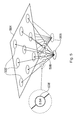
- a self-organising map consists of input nodes 506 and output nodes 502 in a two-dimensional array or grid of nodes illustrated as a two-dimensional plane 504. There are as many input nodes as there are values in the feature vectors being used to train the map. Each of the output nodes on the map is connected to the input nodes by weighted connections 508 (one weight per connection).
- each of these weights is set to a random value, and then, through an iterative process, the weights are "trained".
- the map is trained by presenting each feature vector to the input nodes of the map.
- the "closest" output node is calculated by computing the Euclidean distance between the input vector and weights associated with each of the output nodes.
- the closest node, identified by the smallest Euclidean distance between the input vector and the weights associated with that node is designated the "winner” and the weights of this node are trained by slightly changing the values of the weights so that they move "closer" to the input vector.
- the nodes in the neighbourhood of the winning node are also trained, and moved slightly closer to the input vector.
- the concatenated feature vector under test can be presented to the map to see which of the output nodes is closest to the concatenated feature vector under test. It is unlikely that the weights will be identical to the feature vector, and the Euclidean distance between a feature vector and its nearest node on the map is known as its "quantisation error".
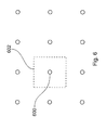
- a potential problem with the process described above is that two identical, or substantially identical, concatenated feature vectors may be mapped to the same node in the array of nodes of the SOM. This does not cause a difficulty in the handling of the data, but does not help with the visualisation of the data on display screen. In particular, when the data is visualised on a display screen, it has been recognised that it would be useful for multiple very similar items to be distinguishable over a single item at a particular node. Therefore, a "dither" component is added to the node position to which each concatenated feature vector is mapped. The dither component is a random addition of ⁇ 1 ⁇ 2 of the node separation.
- a concatenated feature vector for which the mapping process selects an output node 600 has a dither component added so that it in fact may be mapped to any map position around a node 600 within the area 602 bounded by dotted lines on Figure 6 .
- the concatenated feature vector can be considered to map to positions on the plane of Figure 6 at node positions other than the "output nodes" of the SOM process.
- the self organising map is a useful tool for visualising clustering of concatenated reduced feature vectors and so indicating whether or not a feature vector applied to the self organising map is within a normal cluster, because of the processing required to place the concatenated reduced feature vector into the self-organising map, it is useful to calculate the anomaly value using the concatenated reduced feature vector data which is not included in the self-organising map. However, it is also possible to calculate the anomaly value using the self-organising map as explained below.
- the Euclidean distance between the concatenated feature vector under test and the trained set of concatenated feature vectors is determined. This is a similar measure to the quantisation error described with respect to the self-organising map and the quantisation error represents the anomaly value. Thus, if the Euclidian distance is above a threshold, an anomaly is deemed to exist.
- a self-organising map may be generated for each time-span for which the security system 300 is trained. Additionally, or alternatively, the same or different self-organising map may be generated for the concatenated feature vector over an entire typical day.
- the concatenated feature vectors are generated every 40ms it is unlikely that an anomaly value generated from one feature vector would be sufficiently large to constitute a situation which may be considered to be a breach of security or an incident of which the security guard needs to be made aware. This means that the anomaly value indicated by one feature vector does not in itself determine whether or not the trigger signal is generated.
- the anomaly value is an indication of the degree of how much one scene from one location varies from the "normal" scene from the same location. However, a trigger is a situation to which a security guard should be notified.
- a trigger signal may be generated.
- every concatenated feature vector generates an anomaly value over that threshold in order to generate the trigger signal. It may be for instance that only 80% of concatenated feature vectors over a particular period need to exceed the anomaly threshold value for the trigger signal to be generated.
- the trigger signal is generated in response to a sequence of comparisons between the concatenated feature vector of the location under surveillance and the concatenated feature vector generated when the system was being trained at the corresponding time.
- the trigger signal When a trigger signal is generated, the trigger signal is fed to the monitor system 312.
- the trigger signal notifies to the monitor system 312 that a situation is occurring at the location under the surveillance of the security camera 302 of which the security guard monitoring the output feed of the security camera 302 should be made aware.
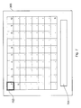
- the processor 306 In response to the trigger signal, the processor 306 notifies the security guard of the situation, and assists in identifying the location.
- the output video feed from security camera 302 may be outlined by a flashing border 702 as shown in Figure 7 .
- HMM Hidden Markov Model
- a temporal sequence of feature vectors and are used to model a sequence of events.
- violent disorder on a street may have a certain hue and motion characteristic followed by high audio power, which, in turn, is followed by certain other motion characteristics.
- these characteristics may or may not have an anomaly value that exceeds the anomaly threshold value.
- the individual characteristics may or may not indicate an anomaly in the scene.
- the HMM would analyse the feature vectors and would output a probability value indicating the probability that a fight is occurring on the basis of the HMM and the characteristic feature vectors. If the probability is above a certain probability threshold, a trigger signal would be generated. In the trigger signal of one embodiment, details of the type of incident (which in this case is a fight) would also be provided, although this is not necessary. It is envisaged that the HMM would model many different incidents, for example left luggage on a station platform, depending on the location under surveillance. It is explained later how these different HMMs are provided to the security system 300. In one embodiment, it is envisaged that for each different HMM which models a different incident, a different ranking, indicating the prominence that each incident should be given, will be attributed to each incident.
- the trigger signal includes the indication of the type of incident as this allows the prominence to be determined.
- the trigger signal could indicate the level of prominence the incident should have instead of details of the incident. This would potentially reduce the amount of data needing to be transferred around the security system 300.
- the business logic may be generated at production of the security camera 302.
- the business logic in one embodiment, can be updated in two distinct ways using a trigger setup signal from the monitor system 312 to the anomaly value and trigger processor 310.
- the business logic can be updated by feedback from the security guard.
- the concatenated feature vectors and corresponding raw input sensory data are stored in the archive 314, if the security guard notices a new incident on his or her monitor 306 to which he should be made aware, he or she can activate the trigger setup signal.
- the trigger setup signal can be stored in the archive 314 and/or the archive 314 of raw sensory data will be played back to the security guard on the monitor 306.
- the security guard can then establish the start and end points of the incidents.
- the security guard would use a toolbar 407 positioned under the output feeds of the security cameras on monitor 306 in order to control the input data and generate the trigger signal.
- the feature vectors generated from the raw sensory data of this defined situation can be used by the business logic to define a new trigger condition.
- this method of updating will require a skilled security guard and will also take up a large proportion of time restricting the effectiveness of the security guard in dealing with other incidents. This is because the security guard is not able to monitor the other security cameras in the system as closely whilst generating the trigger signal.
- the trigger setup signal is defined remotely to the security system 300.
- the trigger setup signal generated by the security guard which is stored in the archive 314 is used as a flag so that raw data which is in the vicinity of the flag (i.e. temporally before and after the incident) is a proxy version of the archived material.
- raw data which is a predetermined time before and after the flag is stored separately as proxy data.
- the proxy data may include video, audio and/or sensor data.
- the proxy data is transferred, in addition to the associated feature vectors and associated raw data over a network 316 to the security maintenance system 320.
- the network 316 may be the Internet, a cellular network, a local area network or some other network which is remote to the monitor system 312.
- the security maintenance system 320 is used to generate the trigger update signal as will be explained hereinafter.
- a highly skilled person may view the proxy data and identify start and stop locations within the raw data that best describe the start and stop of the situation respectively.
- the highly skilled person would interact with the remote processor 320 using terminal 318. From this information, the business logic can be derived. After the business logic for the trigger has been derived, it is transferred back to the processor 312 via the network 316.
- the trigger update signal is fed from processor 312 to the anomaly and trigger processor 310. It is envisaged to increase the security of the system, the proxy data, the concatenated feature vectors, the anomaly value and the trigger update signal are transferred over a secure layer in the network 316.
- the expert sat at terminal 318 can generate all the trigger update signals from viewing the raw data in accordance with requirements set down by the operators of the security system 300.
- the operators of the security maintenance system 320 would work with the operators of the security system 300 to generate a list of criteria which would cause triggers.
- the highly skilled person sat at terminal 318 would then review all the raw data to find such situations and would thus generate trigger update signals complying with the requirements set down by the operators.
- raw data provided from other sources may be used to generate such business logic.
- the other sources may be archived footage from the same security system 300 or different security systems operated by the same operating company or freely available footage. It is unlikely, although still possible, that security footage from security systems operated by different companies would be used as this may be seen as compromising the security of the other company.
- the supplier of the security system 300 may also be the operator of the remote processor 320.
- the purchaser of the security system 300 can be offered different levels of service.
- the security system 300 may be a system that uses the anomaly value exceeding the threshold only to generate the trigger signal. Specifically, in this case, the length of time of such an anomaly value exceeding the predetermined threshold being used to generate the trigger.
- the purchaser may be offered the facility to allow the security guard to generate triggers and the security guard to review the data to refine the business logic in the system.
- the purchaser may be offered the facility to have the business logic further improved by having highly skilled operators of terminal 318 review the proxy data generated in accordance with the guard implemented trigger signal.
- the purchaser may wish to have the highly skilled operator review all the raw data and generate triggers and business logic in accordance with certain criterion or criteria set down by the purchaser. It is envisaged that the purchaser will pay different amounts of money for the different levels of service. Further, it is envisaged that the services involving the generation of business logic and/or trigger update signals will be a subscription based service. In other words, the purchaser needs to pay a subscription to the operator of the remote processor to maintain the level of service. Also, it is possible that the operator may wish to pay a "one-off" fee and ask the operator of the remote processor 320 to provide such a service once.
- the security system 300 could be applied to presently installed security systems 300.
- the security system will record image data only when the trigger signal is generated. This reduces the amount of material that the system has to store.
Applications Claiming Priority (1)
| Application Number | Priority Date | Filing Date | Title |
|---|---|---|---|
| GB0711956A GB2450478A (en) | 2007-06-20 | 2007-06-20 | A security device and system |
Publications (2)
| Publication Number | Publication Date |
|---|---|
| EP2009604A1 true EP2009604A1 (fr) | 2008-12-31 |
| EP2009604B1 EP2009604B1 (fr) | 2009-12-16 |
Family
ID=38352597
Family Applications (1)
| Application Number | Title | Priority Date | Filing Date |
|---|---|---|---|
| EP08251760A Not-in-force EP2009604B1 (fr) | 2007-06-20 | 2008-05-20 | Dispositif de sécurité et système |
Country Status (8)
| Country | Link |
|---|---|
| US (1) | US8577082B2 (fr) |
| EP (1) | EP2009604B1 (fr) |
| JP (1) | JP5267782B2 (fr) |
| CN (1) | CN101329804B (fr) |
| AT (1) | ATE452393T1 (fr) |
| DE (1) | DE602008000407D1 (fr) |
| ES (1) | ES2338191T3 (fr) |
| GB (1) | GB2450478A (fr) |
Cited By (1)
| Publication number | Priority date | Publication date | Assignee | Title |
|---|---|---|---|---|
| WO2022265803A1 (fr) * | 2021-06-18 | 2022-12-22 | Microsoft Technology Licensing, Llc | Évaluation de la probabilité d'alertes d'incident de sécurité |
Families Citing this family (21)
| Publication number | Priority date | Publication date | Assignee | Title |
|---|---|---|---|---|
| US8711217B2 (en) | 2000-10-24 | 2014-04-29 | Objectvideo, Inc. | Video surveillance system employing video primitives |
| US8564661B2 (en) | 2000-10-24 | 2013-10-22 | Objectvideo, Inc. | Video analytic rule detection system and method |
| US9892606B2 (en) | 2001-11-15 | 2018-02-13 | Avigilon Fortress Corporation | Video surveillance system employing video primitives |
| US7424175B2 (en) | 2001-03-23 | 2008-09-09 | Objectvideo, Inc. | Video segmentation using statistical pixel modeling |
| KR101392294B1 (ko) | 2006-04-17 | 2014-05-27 | 오브젝트비디오 인코퍼레이티드 | 통계적인 픽셀 모델링을 이용한 비디오 분할 |
| US20090028517A1 (en) * | 2007-07-27 | 2009-01-29 | The University Of Queensland | Real-time near duplicate video clip detection method |
| US9141860B2 (en) | 2008-11-17 | 2015-09-22 | Liveclips Llc | Method and system for segmenting and transmitting on-demand live-action video in real-time |
| US8112521B2 (en) * | 2010-02-25 | 2012-02-07 | General Electric Company | Method and system for security maintenance in a network |
| RU2460142C1 (ru) * | 2011-04-26 | 2012-08-27 | Владимир Андреевич Куделькин | Способ защиты линейного участка границы |
| CN102446503A (zh) * | 2011-10-28 | 2012-05-09 | 广东威创视讯科技股份有限公司 | 一种用于大拼接墙信号源报警的窗口表现方法及系统 |
| US8418249B1 (en) * | 2011-11-10 | 2013-04-09 | Narus, Inc. | Class discovery for automated discovery, attribution, analysis, and risk assessment of security threats |
| US9367745B2 (en) | 2012-04-24 | 2016-06-14 | Liveclips Llc | System for annotating media content for automatic content understanding |
| US20130283143A1 (en) | 2012-04-24 | 2013-10-24 | Eric David Petajan | System for Annotating Media Content for Automatic Content Understanding |
| US9734702B2 (en) | 2015-05-21 | 2017-08-15 | Google Inc. | Method and system for consolidating events across sensors |
| AU2016404516B2 (en) * | 2016-04-28 | 2019-09-26 | Motorola Solutions, Inc. | Method and device for incident situation prediction |
| US11545013B2 (en) * | 2016-10-26 | 2023-01-03 | A9.Com, Inc. | Customizable intrusion zones for audio/video recording and communication devices |
| RU2697617C2 (ru) * | 2017-09-19 | 2019-08-15 | Владимир Иванович Яцков | Извещатель в.и. яцкова с ёмкостным и лучевым средствами обнаружения |
| KR102079378B1 (ko) * | 2017-09-26 | 2020-02-19 | 고려대학교 산학협력단 | 영상 복원 방법 및 그 장치 |
| US10186124B1 (en) * | 2017-10-26 | 2019-01-22 | Scott Charles Mullins | Behavioral intrusion detection system |
| KR20210153089A (ko) | 2019-04-10 | 2021-12-16 | 스캇 찰스 멀린스 | 모니터링 시스템 |
| EP3989537B1 (fr) * | 2020-10-23 | 2023-05-03 | Axis AB | Génération d'alerte basée sur la détection d'événement dans un flux vidéo |
Citations (5)
| Publication number | Priority date | Publication date | Assignee | Title |
|---|---|---|---|---|
| EP1324290A2 (fr) * | 2001-12-25 | 2003-07-02 | Matsushita Electric Industrial Co., Ltd. | Dispositif et système de détection d'anomalies |
| WO2004045215A1 (fr) * | 2002-11-12 | 2004-05-27 | Intellivid Corporation | Procede et systeme pour la localisation et la surveillance de comportement d'objets multiples se deplaçant a travers une pluralite de champ de vision |
| US6961703B1 (en) | 2000-09-13 | 2005-11-01 | Itt Manufacturing Enterprises, Inc. | Method for speech processing involving whole-utterance modeling |
| US20060228005A1 (en) * | 2005-04-08 | 2006-10-12 | Canon Kabushiki Kaisha | Information processing apparatus and information processing method |
| GB2433173A (en) * | 2005-12-06 | 2007-06-13 | Bosch Gmbh Robert | Calculating the field of view of a camera based upon pan, tilt and zoom commands used to control the position of the camera |
Family Cites Families (14)
| Publication number | Priority date | Publication date | Assignee | Title |
|---|---|---|---|---|
| JP3337197B2 (ja) | 1997-04-04 | 2002-10-21 | 富士重工業株式会社 | 車外監視装置 |
| US6954859B1 (en) * | 1999-10-08 | 2005-10-11 | Axcess, Inc. | Networked digital security system and methods |
| GB0028162D0 (en) * | 2000-11-20 | 2001-01-03 | Sentec Ltd | Distributed image processing technology and services |
| JP3926572B2 (ja) * | 2001-03-02 | 2007-06-06 | 株式会社日立製作所 | 画像監視方法、画像監視装置及び記憶媒体 |
| US7180429B2 (en) * | 2002-02-14 | 2007-02-20 | Intel Corporation | Slow motion detection system |
| US7227893B1 (en) * | 2002-08-22 | 2007-06-05 | Xlabs Holdings, Llc | Application-specific object-based segmentation and recognition system |
| EP1769635A2 (fr) * | 2004-06-01 | 2007-04-04 | L-3 Communications Corporation | Alarme visuelle/par flash video |
| US20060018516A1 (en) * | 2004-07-22 | 2006-01-26 | Masoud Osama T | Monitoring activity using video information |
| US7606425B2 (en) * | 2004-09-09 | 2009-10-20 | Honeywell International Inc. | Unsupervised learning of events in a video sequence |
| GB2427319B (en) * | 2005-06-13 | 2008-06-25 | John Hendrickson | Intelligent mobile remote monitoring security system |
| US9036028B2 (en) * | 2005-09-02 | 2015-05-19 | Sensormatic Electronics, LLC | Object tracking and alerts |
| US7733224B2 (en) * | 2006-06-30 | 2010-06-08 | Bao Tran | Mesh network personal emergency response appliance |
| JP4641492B2 (ja) | 2005-11-16 | 2011-03-02 | 日本電信電話株式会社 | 特異映像検出装置、特異映像検出方法およびプログラム |
| WO2008016679A2 (fr) * | 2006-08-02 | 2008-02-07 | 24Eight Llc | Système sans fil de détection et d'alarme suivant les entrées et les chutes dans une piscine utilisant un procédé et un appareil sans fil en 3d de détection de données d'accélération et d'énergie |
-
2007
- 2007-06-20 GB GB0711956A patent/GB2450478A/en not_active Withdrawn
-
2008
- 2008-05-20 DE DE602008000407T patent/DE602008000407D1/de active Active
- 2008-05-20 ES ES08251760T patent/ES2338191T3/es active Active
- 2008-05-20 EP EP08251760A patent/EP2009604B1/fr not_active Not-in-force
- 2008-05-20 AT AT08251760T patent/ATE452393T1/de not_active IP Right Cessation
- 2008-05-27 US US12/127,394 patent/US8577082B2/en not_active Expired - Fee Related
- 2008-06-20 CN CN2008101253524A patent/CN101329804B/zh not_active Expired - Fee Related
- 2008-06-20 JP JP2008162572A patent/JP5267782B2/ja not_active Expired - Fee Related
Patent Citations (5)
| Publication number | Priority date | Publication date | Assignee | Title |
|---|---|---|---|---|
| US6961703B1 (en) | 2000-09-13 | 2005-11-01 | Itt Manufacturing Enterprises, Inc. | Method for speech processing involving whole-utterance modeling |
| EP1324290A2 (fr) * | 2001-12-25 | 2003-07-02 | Matsushita Electric Industrial Co., Ltd. | Dispositif et système de détection d'anomalies |
| WO2004045215A1 (fr) * | 2002-11-12 | 2004-05-27 | Intellivid Corporation | Procede et systeme pour la localisation et la surveillance de comportement d'objets multiples se deplaçant a travers une pluralite de champ de vision |
| US20060228005A1 (en) * | 2005-04-08 | 2006-10-12 | Canon Kabushiki Kaisha | Information processing apparatus and information processing method |
| GB2433173A (en) * | 2005-12-06 | 2007-06-13 | Bosch Gmbh Robert | Calculating the field of view of a camera based upon pan, tilt and zoom commands used to control the position of the camera |
Cited By (1)
| Publication number | Priority date | Publication date | Assignee | Title |
|---|---|---|---|---|
| WO2022265803A1 (fr) * | 2021-06-18 | 2022-12-22 | Microsoft Technology Licensing, Llc | Évaluation de la probabilité d'alertes d'incident de sécurité |
Also Published As
| Publication number | Publication date |
|---|---|
| CN101329804B (zh) | 2012-05-30 |
| EP2009604B1 (fr) | 2009-12-16 |
| ES2338191T3 (es) | 2010-05-04 |
| CN101329804A (zh) | 2008-12-24 |
| US8577082B2 (en) | 2013-11-05 |
| JP2009003940A (ja) | 2009-01-08 |
| US20080317286A1 (en) | 2008-12-25 |
| JP5267782B2 (ja) | 2013-08-21 |
| ATE452393T1 (de) | 2010-01-15 |
| DE602008000407D1 (de) | 2010-01-28 |
| GB2450478A (en) | 2008-12-31 |
| GB0711956D0 (en) | 2007-08-01 |
Similar Documents
| Publication | Publication Date | Title |
|---|---|---|
| EP2009604B1 (fr) | Dispositif de sécurité et système | |
| EP1668921B1 (fr) | Appareil et procede informatise pour determiner les relations de champs de vision entre plusieurs capteurs d'image | |
| US8675074B2 (en) | Custom video composites for surveillance applications | |
| US7633520B2 (en) | Method and apparatus for providing a scalable multi-camera distributed video processing and visualization surveillance system | |
| KR102058452B1 (ko) | IoT 융합 지능형 영상분석 플랫폼 시스템 | |
| JP2014512768A (ja) | ビデオ監視システム及び方法 | |
| KR20080058171A (ko) | 카메라 템퍼링 검출 | |
| KR20110130033A (ko) | 행동패턴 데이터베이스를 이용한 능동형 영상감시 시스템 및 그 방법 | |
| CN111488803A (zh) | 一种融合目标检测和目标跟踪的机场目标行为理解系统 | |
| CN116165981A (zh) | 一种工业行业安全生产智能监控系统 | |
| JP5088463B2 (ja) | 監視システム | |
| KR20160093253A (ko) | 영상 기반 이상 흐름 감지 방법 및 그 시스템 | |
| US9870518B2 (en) | Data processing system | |
| CN109120896B (zh) | 安防视频监控卫士系统 | |
| KR20220077404A (ko) | 근로자 안전을 위한 다단계 작업현장 안전 관제 방법 및 시스템 | |
| US9111237B2 (en) | Evaluating an effectiveness of a monitoring system | |
| KR20230103890A (ko) | 멀티-모달 비디오 캡셔닝 기반 영상 보안 시스템 및 방법 | |
| KR101870900B1 (ko) | 다목적 감시 이원화 시스템의 통합 운영시스템 및 그 운영방법 | |
| CN110853267A (zh) | 一种基于dsp的校园基础设施安全隐患检测系统 | |
| CN210667061U (zh) | 一种基于dsp的校园基础设施安全隐患检测系统 | |
| Kaur et al. | Framework for FOGIoT based Smart Video Surveillance System (SVSS) | |
| WO2013085377A1 (fr) | Procédé et système servant à établir une priorité dans les affichages d'un système de surveillance | |
| KR101506153B1 (ko) | 교통량 적응형 차량번호 인식시스템 | |
| CN117612060A (zh) | 基于人工智能检测的视频预警系统、方法、设备及介质 | |
| CN117523668A (zh) | 时空动作网络的异常行为检测方法 |
Legal Events
| Date | Code | Title | Description |
|---|---|---|---|
| PUAI | Public reference made under article 153(3) epc to a published international application that has entered the european phase |
Free format text: ORIGINAL CODE: 0009012 |
|
| AK | Designated contracting states |
Kind code of ref document: A1 Designated state(s): AT BE BG CH CY CZ DE DK EE ES FI FR GB GR HR HU IE IS IT LI LT LU LV MC MT NL NO PL PT RO SE SI SK TR |
|
| AX | Request for extension of the european patent |
Extension state: AL BA MK RS |
|
| 17P | Request for examination filed |
Effective date: 20090326 |
|
| GRAP | Despatch of communication of intention to grant a patent |
Free format text: ORIGINAL CODE: EPIDOSNIGR1 |
|
| AKX | Designation fees paid |
Designated state(s): AT BE BG CH CY CZ DE DK EE ES FI FR GB GR HR HU IE IS IT LI LT LU LV MC MT NL NO PL PT RO SE SI SK TR |
|
| GRAS | Grant fee paid |
Free format text: ORIGINAL CODE: EPIDOSNIGR3 |
|
| GRAA | (expected) grant |
Free format text: ORIGINAL CODE: 0009210 |
|
| AK | Designated contracting states |
Kind code of ref document: B1 Designated state(s): AT BE BG CH CY CZ DE DK EE ES FI FR GB GR HR HU IE IS IT LI LT LU LV MC MT NL NO PL PT RO SE SI SK TR |
|
| REG | Reference to a national code |
Ref country code: GB Ref legal event code: FG4D |
|
| REG | Reference to a national code |
Ref country code: CH Ref legal event code: EP |
|
| REG | Reference to a national code |
Ref country code: IE Ref legal event code: FG4D |
|
| REF | Corresponds to: |
Ref document number: 602008000407 Country of ref document: DE Date of ref document: 20100128 Kind code of ref document: P |
|
| REG | Reference to a national code |
Ref country code: SE Ref legal event code: TRGR |
|
| REG | Reference to a national code |
Ref country code: NL Ref legal event code: VDEP Effective date: 20091216 |
|
| PG25 | Lapsed in a contracting state [announced via postgrant information from national office to epo] |
Ref country code: FI Free format text: LAPSE BECAUSE OF FAILURE TO SUBMIT A TRANSLATION OF THE DESCRIPTION OR TO PAY THE FEE WITHIN THE PRESCRIBED TIME-LIMIT Effective date: 20091216 Ref country code: LT Free format text: LAPSE BECAUSE OF FAILURE TO SUBMIT A TRANSLATION OF THE DESCRIPTION OR TO PAY THE FEE WITHIN THE PRESCRIBED TIME-LIMIT Effective date: 20091216 Ref country code: NO Free format text: LAPSE BECAUSE OF FAILURE TO SUBMIT A TRANSLATION OF THE DESCRIPTION OR TO PAY THE FEE WITHIN THE PRESCRIBED TIME-LIMIT Effective date: 20100316 |
|
| REG | Reference to a national code |
Ref country code: ES Ref legal event code: FG2A Ref document number: 2338191 Country of ref document: ES Kind code of ref document: T3 |
|
| LTIE | Lt: invalidation of european patent or patent extension |
Effective date: 20091216 |
|
| PG25 | Lapsed in a contracting state [announced via postgrant information from national office to epo] |
Ref country code: SI Free format text: LAPSE BECAUSE OF FAILURE TO SUBMIT A TRANSLATION OF THE DESCRIPTION OR TO PAY THE FEE WITHIN THE PRESCRIBED TIME-LIMIT Effective date: 20091216 Ref country code: HR Free format text: LAPSE BECAUSE OF FAILURE TO SUBMIT A TRANSLATION OF THE DESCRIPTION OR TO PAY THE FEE WITHIN THE PRESCRIBED TIME-LIMIT Effective date: 20091216 Ref country code: PL Free format text: LAPSE BECAUSE OF FAILURE TO SUBMIT A TRANSLATION OF THE DESCRIPTION OR TO PAY THE FEE WITHIN THE PRESCRIBED TIME-LIMIT Effective date: 20091216 Ref country code: LV Free format text: LAPSE BECAUSE OF FAILURE TO SUBMIT A TRANSLATION OF THE DESCRIPTION OR TO PAY THE FEE WITHIN THE PRESCRIBED TIME-LIMIT Effective date: 20091216 |
|
| PG25 | Lapsed in a contracting state [announced via postgrant information from national office to epo] |
Ref country code: AT Free format text: LAPSE BECAUSE OF FAILURE TO SUBMIT A TRANSLATION OF THE DESCRIPTION OR TO PAY THE FEE WITHIN THE PRESCRIBED TIME-LIMIT Effective date: 20091216 |
|
| PG25 | Lapsed in a contracting state [announced via postgrant information from national office to epo] |
Ref country code: RO Free format text: LAPSE BECAUSE OF FAILURE TO SUBMIT A TRANSLATION OF THE DESCRIPTION OR TO PAY THE FEE WITHIN THE PRESCRIBED TIME-LIMIT Effective date: 20091216 Ref country code: IS Free format text: LAPSE BECAUSE OF FAILURE TO SUBMIT A TRANSLATION OF THE DESCRIPTION OR TO PAY THE FEE WITHIN THE PRESCRIBED TIME-LIMIT Effective date: 20100416 Ref country code: BG Free format text: LAPSE BECAUSE OF FAILURE TO SUBMIT A TRANSLATION OF THE DESCRIPTION OR TO PAY THE FEE WITHIN THE PRESCRIBED TIME-LIMIT Effective date: 20100316 Ref country code: EE Free format text: LAPSE BECAUSE OF FAILURE TO SUBMIT A TRANSLATION OF THE DESCRIPTION OR TO PAY THE FEE WITHIN THE PRESCRIBED TIME-LIMIT Effective date: 20091216 Ref country code: NL Free format text: LAPSE BECAUSE OF FAILURE TO SUBMIT A TRANSLATION OF THE DESCRIPTION OR TO PAY THE FEE WITHIN THE PRESCRIBED TIME-LIMIT Effective date: 20091216 |
|
| PG25 | Lapsed in a contracting state [announced via postgrant information from national office to epo] |
Ref country code: BE Free format text: LAPSE BECAUSE OF FAILURE TO SUBMIT A TRANSLATION OF THE DESCRIPTION OR TO PAY THE FEE WITHIN THE PRESCRIBED TIME-LIMIT Effective date: 20091216 Ref country code: SK Free format text: LAPSE BECAUSE OF FAILURE TO SUBMIT A TRANSLATION OF THE DESCRIPTION OR TO PAY THE FEE WITHIN THE PRESCRIBED TIME-LIMIT Effective date: 20091216 Ref country code: CZ Free format text: LAPSE BECAUSE OF FAILURE TO SUBMIT A TRANSLATION OF THE DESCRIPTION OR TO PAY THE FEE WITHIN THE PRESCRIBED TIME-LIMIT Effective date: 20091216 |
|
| PLBE | No opposition filed within time limit |
Free format text: ORIGINAL CODE: 0009261 |
|
| STAA | Information on the status of an ep patent application or granted ep patent |
Free format text: STATUS: NO OPPOSITION FILED WITHIN TIME LIMIT |
|
| PG25 | Lapsed in a contracting state [announced via postgrant information from national office to epo] |
Ref country code: GR Free format text: LAPSE BECAUSE OF FAILURE TO SUBMIT A TRANSLATION OF THE DESCRIPTION OR TO PAY THE FEE WITHIN THE PRESCRIBED TIME-LIMIT Effective date: 20100317 Ref country code: CY Free format text: LAPSE BECAUSE OF FAILURE TO SUBMIT A TRANSLATION OF THE DESCRIPTION OR TO PAY THE FEE WITHIN THE PRESCRIBED TIME-LIMIT Effective date: 20091216 |
|
| 26N | No opposition filed |
Effective date: 20100917 |
|
| PG25 | Lapsed in a contracting state [announced via postgrant information from national office to epo] |
Ref country code: MC Free format text: LAPSE BECAUSE OF NON-PAYMENT OF DUE FEES Effective date: 20100531 |
|
| PG25 | Lapsed in a contracting state [announced via postgrant information from national office to epo] |
Ref country code: DK Free format text: LAPSE BECAUSE OF FAILURE TO SUBMIT A TRANSLATION OF THE DESCRIPTION OR TO PAY THE FEE WITHIN THE PRESCRIBED TIME-LIMIT Effective date: 20091216 |
|
| PG25 | Lapsed in a contracting state [announced via postgrant information from national office to epo] |
Ref country code: IT Free format text: LAPSE BECAUSE OF FAILURE TO SUBMIT A TRANSLATION OF THE DESCRIPTION OR TO PAY THE FEE WITHIN THE PRESCRIBED TIME-LIMIT Effective date: 20091216 |
|
| PG25 | Lapsed in a contracting state [announced via postgrant information from national office to epo] |
Ref country code: MT Free format text: LAPSE BECAUSE OF FAILURE TO SUBMIT A TRANSLATION OF THE DESCRIPTION OR TO PAY THE FEE WITHIN THE PRESCRIBED TIME-LIMIT Effective date: 20091216 Ref country code: IE Free format text: LAPSE BECAUSE OF NON-PAYMENT OF DUE FEES Effective date: 20100520 |
|
| PG25 | Lapsed in a contracting state [announced via postgrant information from national office to epo] |
Ref country code: LU Free format text: LAPSE BECAUSE OF NON-PAYMENT OF DUE FEES Effective date: 20100520 Ref country code: HU Free format text: LAPSE BECAUSE OF FAILURE TO SUBMIT A TRANSLATION OF THE DESCRIPTION OR TO PAY THE FEE WITHIN THE PRESCRIBED TIME-LIMIT Effective date: 20100617 Ref country code: PT Free format text: LAPSE BECAUSE OF FAILURE TO SUBMIT A TRANSLATION OF THE DESCRIPTION OR TO PAY THE FEE WITHIN THE PRESCRIBED TIME-LIMIT Effective date: 20100516 |
|
| PG25 | Lapsed in a contracting state [announced via postgrant information from national office to epo] |
Ref country code: TR Free format text: LAPSE BECAUSE OF FAILURE TO SUBMIT A TRANSLATION OF THE DESCRIPTION OR TO PAY THE FEE WITHIN THE PRESCRIBED TIME-LIMIT Effective date: 20091216 |
|
| REG | Reference to a national code |
Ref country code: CH Ref legal event code: PL |
|
| PG25 | Lapsed in a contracting state [announced via postgrant information from national office to epo] |
Ref country code: LI Free format text: LAPSE BECAUSE OF NON-PAYMENT OF DUE FEES Effective date: 20120531 Ref country code: CH Free format text: LAPSE BECAUSE OF NON-PAYMENT OF DUE FEES Effective date: 20120531 |
|
| PGFP | Annual fee paid to national office [announced via postgrant information from national office to epo] |
Ref country code: GB Payment date: 20140521 Year of fee payment: 7 |
|
| PGFP | Annual fee paid to national office [announced via postgrant information from national office to epo] |
Ref country code: FR Payment date: 20140527 Year of fee payment: 7 Ref country code: SE Payment date: 20140520 Year of fee payment: 7 Ref country code: ES Payment date: 20140521 Year of fee payment: 7 |
|
| GBPC | Gb: european patent ceased through non-payment of renewal fee |
Effective date: 20150520 |
|
| REG | Reference to a national code |
Ref country code: FR Ref legal event code: ST Effective date: 20160129 |
|
| PG25 | Lapsed in a contracting state [announced via postgrant information from national office to epo] |
Ref country code: SE Free format text: LAPSE BECAUSE OF NON-PAYMENT OF DUE FEES Effective date: 20150521 |
|
| REG | Reference to a national code |
Ref country code: DE Ref legal event code: R082 Ref document number: 602008000407 Country of ref document: DE Representative=s name: MITSCHERLICH, PATENT- UND RECHTSANWAELTE PARTM, DE Ref country code: DE Ref legal event code: R081 Ref document number: 602008000407 Country of ref document: DE Owner name: SONY EUROPE LTD., WEYBRIDGE, GB Free format text: FORMER OWNER: SONY UNITED KINGDOM LTD., WEYBRIDGE, SURREY KT13 OXW, GB |
|
| PG25 | Lapsed in a contracting state [announced via postgrant information from national office to epo] |
Ref country code: GB Free format text: LAPSE BECAUSE OF NON-PAYMENT OF DUE FEES Effective date: 20150520 |
|
| REG | Reference to a national code |
Ref country code: DE Ref legal event code: R084 Ref document number: 602008000407 Country of ref document: DE |
|
| PG25 | Lapsed in a contracting state [announced via postgrant information from national office to epo] |
Ref country code: FR Free format text: LAPSE BECAUSE OF NON-PAYMENT OF DUE FEES Effective date: 20150601 |
|
| PG25 | Lapsed in a contracting state [announced via postgrant information from national office to epo] |
Ref country code: ES Free format text: LAPSE BECAUSE OF NON-PAYMENT OF DUE FEES Effective date: 20150521 |
|
| REG | Reference to a national code |
Ref country code: ES Ref legal event code: FD2A Effective date: 20180703 |
|
| PGFP | Annual fee paid to national office [announced via postgrant information from national office to epo] |
Ref country code: DE Payment date: 20210421 Year of fee payment: 14 |
|
| REG | Reference to a national code |
Ref country code: DE Ref legal event code: R119 Ref document number: 602008000407 Country of ref document: DE |
|
| PG25 | Lapsed in a contracting state [announced via postgrant information from national office to epo] |
Ref country code: DE Free format text: LAPSE BECAUSE OF NON-PAYMENT OF DUE FEES Effective date: 20221201 |