EP2009338A1 - Conduite renforcée à deux enveloppes et méthode de fabrication - Google Patents
Conduite renforcée à deux enveloppes et méthode de fabrication Download PDFInfo
- Publication number
- EP2009338A1 EP2009338A1 EP08290586A EP08290586A EP2009338A1 EP 2009338 A1 EP2009338 A1 EP 2009338A1 EP 08290586 A EP08290586 A EP 08290586A EP 08290586 A EP08290586 A EP 08290586A EP 2009338 A1 EP2009338 A1 EP 2009338A1
- Authority
- EP
- European Patent Office
- Prior art keywords
- tube
- centering elements
- outer tube
- inner tube
- pipe
- Prior art date
- Legal status (The legal status is an assumption and is not a legal conclusion. Google has not performed a legal analysis and makes no representation as to the accuracy of the status listed.)
- Withdrawn
Links
Images

Classifications
-
- F—MECHANICAL ENGINEERING; LIGHTING; HEATING; WEAPONS; BLASTING
- F16—ENGINEERING ELEMENTS AND UNITS; GENERAL MEASURES FOR PRODUCING AND MAINTAINING EFFECTIVE FUNCTIONING OF MACHINES OR INSTALLATIONS; THERMAL INSULATION IN GENERAL
- F16L—PIPES; JOINTS OR FITTINGS FOR PIPES; SUPPORTS FOR PIPES, CABLES OR PROTECTIVE TUBING; MEANS FOR THERMAL INSULATION IN GENERAL
- F16L9/00—Rigid pipes
- F16L9/02—Rigid pipes of metal
- F16L9/04—Reinforced pipes
- F16L9/047—Reinforced pipes comprising reinforcement rings
-
- F—MECHANICAL ENGINEERING; LIGHTING; HEATING; WEAPONS; BLASTING
- F16—ENGINEERING ELEMENTS AND UNITS; GENERAL MEASURES FOR PRODUCING AND MAINTAINING EFFECTIVE FUNCTIONING OF MACHINES OR INSTALLATIONS; THERMAL INSULATION IN GENERAL
- F16L—PIPES; JOINTS OR FITTINGS FOR PIPES; SUPPORTS FOR PIPES, CABLES OR PROTECTIVE TUBING; MEANS FOR THERMAL INSULATION IN GENERAL
- F16L57/00—Protection of pipes or objects of similar shape against external or internal damage or wear
- F16L57/02—Protection of pipes or objects of similar shape against external or internal damage or wear against cracking or buckling
-
- F—MECHANICAL ENGINEERING; LIGHTING; HEATING; WEAPONS; BLASTING
- F16—ENGINEERING ELEMENTS AND UNITS; GENERAL MEASURES FOR PRODUCING AND MAINTAINING EFFECTIVE FUNCTIONING OF MACHINES OR INSTALLATIONS; THERMAL INSULATION IN GENERAL
- F16L—PIPES; JOINTS OR FITTINGS FOR PIPES; SUPPORTS FOR PIPES, CABLES OR PROTECTIVE TUBING; MEANS FOR THERMAL INSULATION IN GENERAL
- F16L59/00—Thermal insulation in general
- F16L59/06—Arrangements using an air layer or vacuum
- F16L59/065—Arrangements using an air layer or vacuum using vacuum
-
- F—MECHANICAL ENGINEERING; LIGHTING; HEATING; WEAPONS; BLASTING
- F16—ENGINEERING ELEMENTS AND UNITS; GENERAL MEASURES FOR PRODUCING AND MAINTAINING EFFECTIVE FUNCTIONING OF MACHINES OR INSTALLATIONS; THERMAL INSULATION IN GENERAL
- F16L—PIPES; JOINTS OR FITTINGS FOR PIPES; SUPPORTS FOR PIPES, CABLES OR PROTECTIVE TUBING; MEANS FOR THERMAL INSULATION IN GENERAL
- F16L59/00—Thermal insulation in general
- F16L59/14—Arrangements for the insulation of pipes or pipe systems
-
- F—MECHANICAL ENGINEERING; LIGHTING; HEATING; WEAPONS; BLASTING
- F16—ENGINEERING ELEMENTS AND UNITS; GENERAL MEASURES FOR PRODUCING AND MAINTAINING EFFECTIVE FUNCTIONING OF MACHINES OR INSTALLATIONS; THERMAL INSULATION IN GENERAL
- F16L—PIPES; JOINTS OR FITTINGS FOR PIPES; SUPPORTS FOR PIPES, CABLES OR PROTECTIVE TUBING; MEANS FOR THERMAL INSULATION IN GENERAL
- F16L9/00—Rigid pipes
- F16L9/02—Rigid pipes of metal
- F16L9/04—Reinforced pipes
- F16L9/042—Reinforced pipes the reinforcement comprising one or more layers of a helically wound cord, wire or strip
-
- F—MECHANICAL ENGINEERING; LIGHTING; HEATING; WEAPONS; BLASTING
- F16—ENGINEERING ELEMENTS AND UNITS; GENERAL MEASURES FOR PRODUCING AND MAINTAINING EFFECTIVE FUNCTIONING OF MACHINES OR INSTALLATIONS; THERMAL INSULATION IN GENERAL
- F16L—PIPES; JOINTS OR FITTINGS FOR PIPES; SUPPORTS FOR PIPES, CABLES OR PROTECTIVE TUBING; MEANS FOR THERMAL INSULATION IN GENERAL
- F16L9/00—Rigid pipes
- F16L9/18—Double-walled pipes; Multi-channel pipes or pipe assemblies
-
- Y—GENERAL TAGGING OF NEW TECHNOLOGICAL DEVELOPMENTS; GENERAL TAGGING OF CROSS-SECTIONAL TECHNOLOGIES SPANNING OVER SEVERAL SECTIONS OF THE IPC; TECHNICAL SUBJECTS COVERED BY FORMER USPC CROSS-REFERENCE ART COLLECTIONS [XRACs] AND DIGESTS
- Y10—TECHNICAL SUBJECTS COVERED BY FORMER USPC
- Y10T—TECHNICAL SUBJECTS COVERED BY FORMER US CLASSIFICATION
- Y10T29/00—Metal working
- Y10T29/49—Method of mechanical manufacture
- Y10T29/4935—Heat exchanger or boiler making
- Y10T29/49361—Tube inside tube
Definitions
- the present invention relates to the field of jacketed pipes for the transport of fluid.
- a pipe with two envelopes commonly called “pipe-in-pipe” consists of two coaxial metal tubes respectively inner and outer, separated by an annular space filled with an insulating material.
- the inner tube is held in position relative to the outer tube by centering elements, commonly called “centraliser” or “spacer”.
- the spacers are usually ring-shaped.
- Two-envelope pipes are used in particular by the oil industry to convey oil from a wellhead located on the seabed to a treatment plant on the surface of the sea.
- Conduits installed at the bottom of the sea commonly called “flow line” mainly undergo static mechanical stresses
- pipes connecting the bottom of the sea to the surface commonly called “riser” are solicited mechanically statically and dynamically.
- Offshore deposits are carried out to water depths of 1500 m and above. Future developments are envisaged for water depths up to 3000 m and beyond. It is important to have a high mechanical strength pipe.
- Double-walled pipes are mainly used for their good thermal insulation characteristics in order to convey hot oil products in a deep marine environment. Too much cooling of these petroleum products would be problematic both in the normal production regime and in case of production stoppage. A cooling of the oil effluent conveyed can indeed cause an increase in viscosity, paraffin precipitation and flocculation of asphaltenes which increase the viscosity of the effluent and cause deposits that reduce the effective inner diameter of the pipe, or the formation of gas hydrates that can clog the pipe.
- the document FR 2,815,693 proposes an exemplary embodiment of pipe with two envelopes in which the inner tube is not connected to the outer tube.
- pipe-in-pipe type is penalized by the weight of these pipes.
- pipe-in-pipe pipes are among the heaviest pipes laid at sea. This is explained by the fact that the inner pipe must withstand the pressure of the fluid flowing in the pipe and the outer pipe alone. must withstand the external hydrostatic pressure alone.
- the present invention aims to reduce the weight of pipes of the "pipe-in-pipe” type.
- the invention describes a two-shell line in which the centering elements reinforce the mechanical strength of the outer tube.
- the invention describes a reinforced two-shelled pipe comprising a rigid inner tube disposed in a rigid outer tube, the tubes being separated by an annular space, centering elements holding the inner tube in position relative to the outer tube.
- said outer tube resists only at an external pressure at least greater than 50 bar and the centering elements are in contact with the inner tube and with the outer tube so as to reinforce the mechanical strength of the external tube at the pressure. external.
- the centering elements may consist of a material having a Young's modulus greater than 1000 MPa at 20 ° C.
- the centering elements may be made of a material having a thermal conductivity of less than 1 Wm-1.K-1 at a temperature between 0 ° C and 150 ° C.
- the centering elements may comprise rings arranged in the annular space at intervals between 1 and 5 times the outer diameter of the outer tube.
- the centering elements may comprise a band wound in the annular space along a helix.
- the centering elements may comprise studs.
- the annular space may be filled with an insulating material having a thermal conductivity of less than 0.1 Wm -1 .K -1 .
- the annular space may be subjected to a vacuum at a pressure less than 0.1 bar absolute.
- the invention also describes a method of manufacturing a reinforced pipe with two envelopes, said pipe comprising a rigid inner tube disposed in a rigid outer tube, the tubes being separated by an annular space, centering elements holding the tube in position. internal with respect to the outer tube.
- the rigid outer tube is chosen so that said outer tube withstands an external pressure greater than 50 bar and the centering elements are placed in contact with the inner tube and with the outer tube so as to increase the mechanical strength of the outer tube to the external pressure.
- the centering elements it is possible to arrange the centering elements around the inner tube, it is possible to introduce the inner tube provided with the centering elements into the outer tube and it is possible to deform one of the two permanently. tubes so as to bring the centering elements into contact with the inner tube and with the outer tube.
- the inner tube can be introduced into the outer tube and a material can be injected into the annular space so as to form centering elements in contact with the inner tube and with the outer tube.
- the centering elements may be arranged around the inner tube, the inner tube provided with the centering elements may be introduced into the outer tube, and the centering elements may be mechanically clamped against the inner tube and the outer tube.
- An insulating material having a thermal conductivity of less than 0.1 Wm -1 .K -1 may be provided in the annular space.
- the annular space can be evacuated at a pressure of less than 0.1 bar absolute.
- the pipe according to the invention has a better mechanical strength which reduces the thickness of steel used and thus lighten the pipe.
- the pipe according to the invention can be used for the exploitation of deposits located at great depths of water.
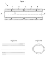
- the pipe 1 with two envelopes of longitudinal axis AA ' comprises an inner casing or tube 2, commonly called “flowline” and an outer casing or tube 3, commonly called “carrier pipe”.
- the inner tube 2 in which the fluid to be transported circulates, ensures the resistance to the internal pressure and the sealing against the transported fluid, for example a petroleum effluent.
- the outer tube 3 ensures the resistance to external pressure and the sealing vis-à-vis the external medium to the pipe 1, for example seawater.
- the tubes 2 and 3 are made of metal material, for example steel, aluminum or titanium.
- the invention can also be implemented with tubes 2 and 3 made of composite material matrix of thermoplastic or thermosetting organic material, reinforced with carbon fibers, glass or other.
- the inner tube 2 is positioned relative to the outer tube 3 by means of centering elements or radial stops 4 so as to be substantially coaxial.
- the centering elements 4 are arranged regularly in the annular space between the tubes 2 and 3, along the pipe 1.
- the annular space between the centering elements 4 is filled with elements 5 of insulating material which is not subject to any significant mechanical loading.
- An insulating material is generally chosen whose thermal conductivity is less than 0.1 Wm -1 .K -1 .
- the insulating material may be arranged by winding thick strips around the inner tube 2.
- the annular space for example at a pressure of less than 0.1 bar absolute, in order to limit the heat exchanges between the tubes 2 and 3.
- the centering elements 4 have the role of reinforcing the mechanical strength of the outer tube.
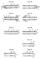
- the ruin of a "pipe-in-pipe” pipe subjected to external pressure occurs by buckling of the outer tube.
- the buckling of a rigid tube that is to say, resistant to an external pressure at least greater than 50 bar, under external pressure can occur in the longitudinal direction of the tube and the section of the tube.
- the solid lines represent the tube before buckling
- the dashed lines represent the tube deformed by buckling.
- the buckling in the longitudinal direction corresponds to a uniform displacement of the generatrices of the tube as represented by the Figure 1A .
- the buckling according to the section corresponds to an ovality of the tube as represented by the Figure 1B .
- reinforcements located on the inner surface of the outer tube are introduced in order to disturb the natural modes of buckling of the outer tube 3.
- the tube 3 is reinforced by means of the centering elements 4.
- centering 4 are in contact with the inner surface of the outer tube 3 and locally strengthens the mechanical strength of the outer tube in order to increase the mechanical strength of the tube to the external pressure.
- it is possible to increase the mechanical strength of the pipe, or the requirements regarding the material or the dimensions of the pipe can be reduced.
- internal and external tubes This makes it possible to reduce the steel thicknesses of the tubes and, therefore, to reduce pipe-in-pipe pipes.
- the inner tube 2 there is no clearance between the inner tube 2, a centering element 4 and the outer tube 3.
- the absence of clearance between the centering elements and the two tubes makes it possible to transmit the forces between the inner tube and the outer tube.
- the two envelopes are mechanically linked and work together to withstand mechanical loads.
- the radial forces applied to the outer surface of the pipe 1 can be distributed between the outer tube and the inner tube.
- the centering elements 4 may be integral with the tubes 3 and / or 2, ie a mechanical connection connects the centering elements 4 to the tube 3 and / or to the tube 2.
- the centering elements 4 may also simply be in contact with the tubes 3 and / or 2 without being attached to these tubes.
- the elements 4 must provide reinforcement zones arranged regularly along the pipe.
- centering elements arranged in the annular space can be placed at an interval of between 1 and 5 times the outer diameter of the outer tube, along the pipe.
- the load taken up by the centering elements 4 is relatively small relative to the load borne by the outer tube subjected to external pressure. Indeed, a recovery of a small portion of the forces generated by the external pressure by the elements 4 sufficiently disrupts the buckling modes and, therefore, increases the resistance to external pressure.
- the elements 4 can take up from 1% to 10% of the forces generated by the external pressure exerted on the tube 3. According to the invention, it is possible to use low strength centering elements with respect to the mechanical strength of the external pipe. .
- the centering elements according to the invention because they are in contact with the inner tube and the outer tube, constitute "thermal bridges", that is to say, a preferred passage of flow between the inner tube and the outer tube.
- a maximum number of the most resistant centering elements is available.
- the number of centering elements is limited and dimensions and materials that are the least heat conducting are chosen. The material, the dimensions and the spacing of the centering elements are chosen so as to limit the heat exchange between the tubes 2 and 3, while maintaining the role of force distributor between these tubes 2 and 3.
- the centering elements 4 in contact with the inner and outer tube, materials having good mechanical properties, preferably having a Young's modulus greater than 1000 MPa at 20 ° C., or even 2000 MPa at 20 ° C., are chosen. as well as adequate thermal properties.
- the thermal conductivity of the material may be less than 1 Wm -1 .K -1 , preferably less than 0.5 or 0.3 Wm -1 .K -1 , at the operating temperature of the pipe, that is, that is, between 0 ° C and 150 ° C.
- the centering elements made of matt glass fiber composite material that is to say short fibers of any orientation, are made in a matrix made of epoxy resin, polyurethane or polypropylene.
- syntactic foam comprising microspheres of glass in an epoxy matrix.
- These two materials limit, in terms of Young's modulus and in terms of thermal conductivity, the range of materials that are well adapted to produce centering elements according to the invention.
- the Figure 2A has an inner tube 3 provided with centering elements in the form of a ring.
- each of the elements 4 is composed of two half-rings.
- the half-rings are assembled around the inner tube 2 for example by screwing a half-ring on the other.
- the centering element 4a is a ring of rectangular section of width 1 and height h.
- the centering element 4b is a trapezoidal section ring, the largest base of the trapezium being in contact with the inner tube 2.
- the centering elements are separated by a distance D.
- the centering element 4 consists of a band wound around the tube 2 in a pitch helix p.
- the upper part of the strip is in contact with the inner wall of the tube 3.
- the centering elements in the form of studs can be produced which are distributed along the pipe.
- the Figures 2C and 2D illustrate the realization of the centering elements in pins P1, P2 and P3 in cylindrical form. It may also take other forms, for example in rectangular shape, of elipse, or of any shape. These pads may be arranged along axes oriented along three radii of the tube 3, regularly distributed at 120 ° relative to each other.
- the base of the cylindrical studs rests on the outer surface of the tube 2.
- the studs extend in radial directions of the tubes 2 and 3 until they come into contact with the inner surface of the tube 3.
- the pads P1, P2 and P3 are disposed substantially in a plane perpendicular to the axis of the pipe.
- the three pads P1 ', P2' and P3 ' are arranged in a plane situated at a distance D from the plane in which the pads P1, P2 and P3 are arranged.
- the series of pads P1 ', P2' and P3 ' can be angularly offset, for example 60 °, relative to the axes of the pads P1, P2 and P3.
- the duct with double envelopes collaborating according to the invention can be manufactured in different ways.
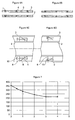
- the crush pressure resistance, commonly referred to as "collapse", of a jacketed pipe subjected to external pressure has been studied.
- the pipe consists of an inner tube separated from an outer tube by syntactic foam centering elements.
- the inner tube has an outer diameter of 10 "(273.1 mm) and the outer tube has an outer diameter of 13.73" (348.7 mm).
- These tubes are made of steel: X65.
- the syntactic foam which consists of an epoxy matrix comprising glass microspheres, has a Young's modulus of 3000 MPa at 20 ° C and 1000 MPa at 130 ° C.
- the rings have a width of 0.04 m and are distributed at a regular interval of 0.9 m.
- the ring-shaped centering elements of rectangular section are in contact with the inner tube. On the other hand, there is a clearance between the centering elements and the outer tube.
- the collapse pressure of the pipe was determined by means of numerical calculations for different values of the clearance between the centering element and the outer pipe.
- the figure 7 presents the curve of the collapse pressure of the pipe as a function of the clearance between the centering element and the tube external.
- the game is indicated by the x-axis in millimeters.
- the collapse pressure indicated by the ordinate axis in bar.
- the pipe has the best resistance to collapse when the clearance between the centering element and the outer tube is zero.
- a clearance of 3 mm is sufficient to remove any mechanical role to the centering element in the holding collapse.
- a 1 mm clearance reduces by half the collapse pressure gain provided by the centering element.
- the pipe according to the invention which proposes to transmit forces between the tubes by the centering elements, has the advantage of being mechanically more resistant to collapse.
Landscapes
- Engineering & Computer Science (AREA)
- General Engineering & Computer Science (AREA)
- Mechanical Engineering (AREA)
- Rigid Pipes And Flexible Pipes (AREA)
Applications Claiming Priority (1)
| Application Number | Priority Date | Filing Date | Title |
|---|---|---|---|
| FR0704706A FR2918149B1 (fr) | 2007-06-29 | 2007-06-29 | Conduite renforcee a deux enveloppes et methode de fabrication. |
Publications (1)
| Publication Number | Publication Date |
|---|---|
| EP2009338A1 true EP2009338A1 (fr) | 2008-12-31 |
Family
ID=39232911
Family Applications (1)
| Application Number | Title | Priority Date | Filing Date |
|---|---|---|---|
| EP08290586A Withdrawn EP2009338A1 (fr) | 2007-06-29 | 2008-06-19 | Conduite renforcée à deux enveloppes et méthode de fabrication |
Country Status (4)
| Country | Link |
|---|---|
| US (1) | US20090000681A1 (pt) |
| EP (1) | EP2009338A1 (pt) |
| BR (1) | BRPI0802163A2 (pt) |
| FR (1) | FR2918149B1 (pt) |
Cited By (8)
| Publication number | Priority date | Publication date | Assignee | Title |
|---|---|---|---|---|
| WO2011128545A1 (fr) * | 2010-04-14 | 2011-10-20 | Total Sa | Conduite pour le transport d'un fluide comprenant un hydrocarbure, et procede de fabrication d'une telle conduite |
| NL2005241C2 (en) * | 2010-08-18 | 2012-02-21 | Heerema Marine Contractors Nl | Pipe element for constructing a double walled pipeline. |
| US8701713B2 (en) | 2010-04-14 | 2014-04-22 | Total Sa | Heating device for a device for transporting a fluid containing a hydrocarbon |
| CN104565576A (zh) * | 2013-10-22 | 2015-04-29 | 中国石油化工股份有限公司 | 一种管道和带接箍的管道 |
| US9046207B2 (en) | 2010-04-14 | 2015-06-02 | Total Sa | Line for transporting a fluid containing a hydrocarbon, and method for producing such a line |
| WO2016023797A1 (de) * | 2014-08-12 | 2016-02-18 | Norma Germany Gmbh | Fluidleitung |
| EP3001083A1 (fr) * | 2014-09-26 | 2016-03-30 | Aerolia | Système et procédé de positionnement d'au moins une entretoise dans une canalisation longitudinale |
| WO2016125011A1 (en) * | 2015-02-03 | 2016-08-11 | Acergy France SAS | Sealing arrangements for subsea pipe-in-pipe systems |
Families Citing this family (25)
| Publication number | Priority date | Publication date | Assignee | Title |
|---|---|---|---|---|
| DE102006027707A1 (de) * | 2006-06-14 | 2007-12-20 | Airbus Deutschland Gmbh | Heckstruktur für ein Luft- oder Raumfahrzeug |
| EP2248648B1 (de) * | 2009-05-05 | 2016-03-30 | Brugg Rohr AG, Holding | Verfahren und Vorrichtung zur Herstellung eines wärmeisolierten Leitungsrohrs |
| CN102840395A (zh) * | 2012-08-28 | 2012-12-26 | 中国海洋石油总公司 | 一种双层保温配重海底管道 |
| US9243726B2 (en) | 2012-10-03 | 2016-01-26 | Aarne H. Reid | Vacuum insulated structure with end fitting and method of making same |
| US20140373954A1 (en) * | 2013-06-24 | 2014-12-25 | Strom W. Smith | Pipe Insulation System and Method |
| WO2015089033A1 (en) * | 2013-12-12 | 2015-06-18 | United Technologies Corporation | Heat-shielded conduit |
| CN104089147B (zh) * | 2014-05-14 | 2016-08-31 | 湘潭大学 | 一种高温烟气间接测温用水冷套换热器的高绝热保温结构 |
| US9188250B1 (en) * | 2014-06-12 | 2015-11-17 | Ronald C. Parsons and Denise M. Parsons | Seals for expandable tubular |
| US20150362120A1 (en) * | 2014-06-12 | 2015-12-17 | Strom W. Smith | Pipe Insulation System and Method |
| CN106555915A (zh) * | 2015-09-28 | 2017-04-05 | 蓝莹 | 一种石油油管的加固装置 |
| CN105299340A (zh) * | 2015-12-09 | 2016-02-03 | 江苏东方电力锅炉配件有限公司 | 一种锅炉用无缝钢管 |
| EP3423854A4 (en) | 2016-03-04 | 2020-01-01 | Concept Group LLC | IMPROVED VACUUM INSULATING ARTICLES WITH REFLECTIVE MATERIAL |
| CA3043868A1 (en) | 2016-11-15 | 2018-05-24 | Concept Group Llc | Multiply-insulated assemblies |
| US11072036B2 (en) * | 2016-12-29 | 2021-07-27 | Spinduction Weld, Inc. | Concentric welded pipes with condition monitoring capability and method of manufacture |
| WO2019014463A1 (en) * | 2017-07-12 | 2019-01-17 | Radhakrishnan Shriram | VACUUM INSULATED ARTICLES ENHANCED WITH REFLECTIVE MATERIAL |
| JP6819498B2 (ja) * | 2017-07-25 | 2021-01-27 | トヨタ自動車株式会社 | 二重断熱壁構造加熱炉 |
| MX2020002128A (es) | 2017-08-25 | 2020-09-28 | Concept Group Llc | Componentes aislados con geometría múltiple y con materiales múltiples. |
| PL422945A1 (pl) * | 2017-09-22 | 2019-03-25 | Normax-Invest Spółka Z Ograniczoną Odpowiedzialnością | Sposób ograniczania ilości płynu chłodniczego, zwłaszcza płynu ulegającego przemianom fazowym, w rurowych wymiennikach ciepła oraz deflektor do realizacji tego sposobu |
| CN107511643B (zh) * | 2017-09-25 | 2023-09-26 | 伊顿上飞(上海)航空管路制造有限公司 | 商用大型客机双壁不锈钢管加工方法及工装 |
| US11906099B2 (en) | 2018-03-21 | 2024-02-20 | Phoenix Environmental, Inc. | Seal on the interstice of double-walled fiberglass pipe |
| CN108638591B (zh) * | 2018-07-02 | 2023-04-18 | 清华大学 | 一种碳素钢-混凝土/水泥砂浆-不锈钢复合海底管道 |
| US20200263813A1 (en) * | 2019-02-20 | 2020-08-20 | Delavan, Inc. | Laser clad manufacturing techniques |
| CN110594534B (zh) * | 2019-07-26 | 2021-01-19 | 中国市政工程中南设计研究总院有限公司 | 一种预制直埋蒸汽保温管绝缘内固定支座 |
| US11369985B2 (en) * | 2019-10-04 | 2022-06-28 | Delavan Inc | Fluid conduits with heat shielding |
| CN112032416A (zh) * | 2020-08-27 | 2020-12-04 | 东台市新杰科机械有限公司 | 一种高抗冲无缝钢管 |
Citations (10)
| Publication number | Priority date | Publication date | Assignee | Title |
|---|---|---|---|---|
| US1140633A (en) * | 1914-10-19 | 1915-05-25 | Charles J Trucano | Insulating system. |
| FR2522548A1 (fr) * | 1982-03-05 | 1983-09-09 | Kuibyshevsky Aviat Institu | Procede de fabrication de tubes multicanaux, filiere pour sa mise en oeuvre et tubes multicanaux obtenus par ledit procede |
| GB2317934A (en) * | 1996-10-04 | 1998-04-08 | Regal Rubber Company Limited | A seal for an annulus between inner and outer pipes |
| GB2318400A (en) * | 1996-10-21 | 1998-04-22 | British Steel Plc | Double walled pipe structures |
| GB2325507A (en) * | 1997-05-23 | 1998-11-25 | T J Corbishley | Tubular structure comprising inner and outer tubular members |
| GB2326210A (en) * | 1997-06-13 | 1998-12-16 | Ramesh Rajagopal | Tube assembly for process fluids using vacuum as thermal insulation |
| FR2815693A1 (fr) | 2000-10-19 | 2002-04-26 | Coflexip | Conduite a double enveloppe pour le transport des fluides, muni d'un dispositif de limitation de propagation d'une deformation du tube externe, et procede de limitation de la propagation |
| WO2003048621A1 (fr) * | 2001-12-04 | 2003-06-12 | Saipem S.A. | Conduite sous-marine renforcee et ensemble de deux conduites coaxiales en comprenant |
| US20060118192A1 (en) * | 2002-08-30 | 2006-06-08 | Cook Robert L | Method of manufacturing an insulated pipeline |
| US20060196568A1 (en) * | 2005-01-10 | 2006-09-07 | Leeser Daniel L | Flexible, compression resistant and highly insulating systems |
Family Cites Families (3)
| Publication number | Priority date | Publication date | Assignee | Title |
|---|---|---|---|---|
| DE1525658C3 (de) * | 1966-06-01 | 1981-10-15 | Goepfert, Lotte, 2000 Hamburg | Wärmeisoliertes Leitungsrohr |
| US6032699A (en) * | 1997-05-19 | 2000-03-07 | Furon Company | Fluid delivery pipe with leak detection |
| DE602004017982D1 (de) * | 2003-05-06 | 2009-01-08 | Aspen Aerogels Inc | Tragendes, leichtes und kompaktes isoliersystem |
-
2007
- 2007-06-29 FR FR0704706A patent/FR2918149B1/fr not_active Expired - Fee Related
-
2008
- 2008-06-19 EP EP08290586A patent/EP2009338A1/fr not_active Withdrawn
- 2008-06-27 US US12/147,711 patent/US20090000681A1/en not_active Abandoned
- 2008-06-30 BR BRPI0802163-5A patent/BRPI0802163A2/pt not_active IP Right Cessation
Patent Citations (10)
| Publication number | Priority date | Publication date | Assignee | Title |
|---|---|---|---|---|
| US1140633A (en) * | 1914-10-19 | 1915-05-25 | Charles J Trucano | Insulating system. |
| FR2522548A1 (fr) * | 1982-03-05 | 1983-09-09 | Kuibyshevsky Aviat Institu | Procede de fabrication de tubes multicanaux, filiere pour sa mise en oeuvre et tubes multicanaux obtenus par ledit procede |
| GB2317934A (en) * | 1996-10-04 | 1998-04-08 | Regal Rubber Company Limited | A seal for an annulus between inner and outer pipes |
| GB2318400A (en) * | 1996-10-21 | 1998-04-22 | British Steel Plc | Double walled pipe structures |
| GB2325507A (en) * | 1997-05-23 | 1998-11-25 | T J Corbishley | Tubular structure comprising inner and outer tubular members |
| GB2326210A (en) * | 1997-06-13 | 1998-12-16 | Ramesh Rajagopal | Tube assembly for process fluids using vacuum as thermal insulation |
| FR2815693A1 (fr) | 2000-10-19 | 2002-04-26 | Coflexip | Conduite a double enveloppe pour le transport des fluides, muni d'un dispositif de limitation de propagation d'une deformation du tube externe, et procede de limitation de la propagation |
| WO2003048621A1 (fr) * | 2001-12-04 | 2003-06-12 | Saipem S.A. | Conduite sous-marine renforcee et ensemble de deux conduites coaxiales en comprenant |
| US20060118192A1 (en) * | 2002-08-30 | 2006-06-08 | Cook Robert L | Method of manufacturing an insulated pipeline |
| US20060196568A1 (en) * | 2005-01-10 | 2006-09-07 | Leeser Daniel L | Flexible, compression resistant and highly insulating systems |
Non-Patent Citations (1)
| Title |
|---|
| G. TOUGH ET AL.: "Nile - Design and Qualification of Reeled Pipe in Pipe for Deepwater", OFFSHORE TECHONOLOGY CONFERENCE, 30 April 2001 (2001-04-30), Houston TX USA, pages 1 - 9 * |
Cited By (22)
| Publication number | Priority date | Publication date | Assignee | Title |
|---|---|---|---|---|
| WO2011128545A1 (fr) * | 2010-04-14 | 2011-10-20 | Total Sa | Conduite pour le transport d'un fluide comprenant un hydrocarbure, et procede de fabrication d'une telle conduite |
| FR2958992A1 (fr) * | 2010-04-14 | 2011-10-21 | Total Sa | Conduite pour le transport d'un fluide comprenant un hydrocarbure, et procede de fabrication d'une telle conduite. |
| US8701713B2 (en) | 2010-04-14 | 2014-04-22 | Total Sa | Heating device for a device for transporting a fluid containing a hydrocarbon |
| US9020333B2 (en) | 2010-04-14 | 2015-04-28 | Total Sa | Line for transporting a fluid containing a hydrocarbon, and method for producing such a line |
| US9046207B2 (en) | 2010-04-14 | 2015-06-02 | Total Sa | Line for transporting a fluid containing a hydrocarbon, and method for producing such a line |
| EA021861B1 (ru) * | 2010-04-14 | 2015-09-30 | Тоталь Са | Трубопровод для транспортировки жидкости, содержащей углеводород, и способ производства такого трубопровода |
| NL2005241C2 (en) * | 2010-08-18 | 2012-02-21 | Heerema Marine Contractors Nl | Pipe element for constructing a double walled pipeline. |
| WO2012023850A1 (en) * | 2010-08-18 | 2012-02-23 | Heerema Marine Contractors Nederland B.V. | Pipe element for constructing a double walled pipeline |
| CN104565576A (zh) * | 2013-10-22 | 2015-04-29 | 中国石油化工股份有限公司 | 一种管道和带接箍的管道 |
| JP2017530284A (ja) * | 2014-08-12 | 2017-10-12 | ノーマ ジャーマニー ゲーエムベーハー | 流体ライン |
| CN106662285A (zh) * | 2014-08-12 | 2017-05-10 | 德国诺玛公司 | 流体管线 |
| WO2016023797A1 (de) * | 2014-08-12 | 2016-02-18 | Norma Germany Gmbh | Fluidleitung |
| US10465831B2 (en) | 2014-08-12 | 2019-11-05 | Norma Germany Gmbh | Fluid line |
| CN106662285B (zh) * | 2014-08-12 | 2020-06-09 | 德国诺玛公司 | 流体管线 |
| EP3180501B1 (de) | 2014-08-12 | 2020-12-23 | NORMA Germany GmbH | Fluidleitung |
| EP3001083A1 (fr) * | 2014-09-26 | 2016-03-30 | Aerolia | Système et procédé de positionnement d'au moins une entretoise dans une canalisation longitudinale |
| FR3026325A1 (fr) * | 2014-09-26 | 2016-04-01 | Aerolia | Systeme et procede de positionnement d'au moins une entretoise dans une canalisation longitudinale |
| US10343348B2 (en) | 2014-09-26 | 2019-07-09 | Aerolia | System and method for positioning at least one spacer in a longitudinal pipe |
| WO2016125011A1 (en) * | 2015-02-03 | 2016-08-11 | Acergy France SAS | Sealing arrangements for subsea pipe-in-pipe systems |
| WO2016125024A1 (en) * | 2015-02-03 | 2016-08-11 | Acergy France SAS | Termination bulkheads for subsea pipe-in-pipe systems |
| US10344539B2 (en) | 2015-02-03 | 2019-07-09 | Acergy France SAS | Sealing arrangements for subsea pipe-in-pipe systems |
| US10435953B2 (en) | 2015-02-03 | 2019-10-08 | Acergy France SAS | Termination bulkheads for subsea pipe-in-pipe systems |
Also Published As
| Publication number | Publication date |
|---|---|
| FR2918149B1 (fr) | 2009-09-25 |
| FR2918149A1 (fr) | 2009-01-02 |
| US20090000681A1 (en) | 2009-01-01 |
| BRPI0802163A2 (pt) | 2009-04-22 |
Similar Documents
| Publication | Publication Date | Title |
|---|---|---|
| EP2009338A1 (fr) | Conduite renforcée à deux enveloppes et méthode de fabrication | |
| EP2737238B1 (fr) | Conduite flexible avec tube d'injection et procede de transport d'un effluent petrolier | |
| EP1597509B1 (fr) | Manchon a insert pour la reparation d'une canalisation de transport de fluide a haute pression | |
| CA2655039C (en) | Method of assembly | |
| US20090250925A1 (en) | Extended collar | |
| EP2340349B1 (fr) | Methode pour alleger une colonne montante avec piece d'usure optimisee | |
| EP0910723A1 (fr) | Dispositif limiteur de courbure d'une conduite flexible | |
| EP3397886B1 (fr) | Embout de connexion d'une ligne flexible, ligne flexible et procédé de montage associés | |
| EP1242765A1 (fr) | Conduite flexible sous-marine de grande longueur a structure evolutive | |
| EP3256771B1 (fr) | Dispositif d'anti-glissement et d'auto-centrage d'un tube interne a l'intérieur d'un tube externe d'un élément de longueur unitaire de conduite sous-marine pour le transport de fluides | |
| CA2538097C (fr) | Dispositif d'espacement et de centrage perfectionne pour conduite rigide a double enveloppe a faible coefficient de transfert thermique | |
| OA10385A (fr) | Raidisseur pour une canalisation flexible à usage en milieu marin | |
| FR2906338A1 (fr) | Element de conduite haute pression comportant un assemblage de tubes frettes et methode de fabrication. | |
| FR3016019A1 (fr) | Conduite tubulaire flexible a haute resistance et procede de fabrication | |
| WO2012001335A1 (fr) | Assemblage d'un tube en matériau composite et d'une pièce métallique tubulaire. | |
| FR3006414A1 (fr) | Conduite flexible de transport de fluide, utilisation et procede associes | |
| FR3027338A1 (fr) | Connexion polyvalente etanche a double butee | |
| FR2620767A1 (fr) | Dispositif de centrage de structures tubulaires dans une canalisation de puits de petrole | |
| WO2015169858A1 (fr) | Ensemble de jonction pour former une conduite | |
| GB2582305A (en) | Bend restrictor | |
| FR2960279A1 (fr) | Faisceau de conduites petrolieres a performance thermique amelioree | |
| FR2833063A1 (fr) | Conduite sous-marine renforcee et ensemble de deux conduites coaxiales en comprenant | |
| WO2016128626A1 (fr) | Garniture d'etancheite annulaire pour canalisation a deux tubes, dispositif et canalisation incorporant ces garnitures et leur procede de fabrication/assemblage | |
| WO2017108501A1 (fr) | Procédé de fabrication d'une conduite et d'une structure tubulaire chemisées mécaniquement | |
| FR3125577A1 (fr) | Conduite pour le transport de fluides avec contrôle du flambement de la chemise interne anticorrosion |
Legal Events
| Date | Code | Title | Description |
|---|---|---|---|
| PUAI | Public reference made under article 153(3) epc to a published international application that has entered the european phase |
Free format text: ORIGINAL CODE: 0009012 |
|
| AK | Designated contracting states |
Kind code of ref document: A1 Designated state(s): AT BE BG CH CY CZ DE DK EE ES FI FR GB GR HR HU IE IS IT LI LT LU LV MC MT NL NO PL PT RO SE SI SK TR |
|
| AX | Request for extension of the european patent |
Extension state: AL BA MK RS |
|
| 17P | Request for examination filed |
Effective date: 20090630 |
|
| AKX | Designation fees paid |
Designated state(s): AT BE BG CH CY CZ DE DK EE ES FI FR GB GR HR HU IE IS IT LI LT LU LV MC MT NL NO PL PT RO SE SI SK TR |
|
| 17Q | First examination report despatched |
Effective date: 20090807 |
|
| RAP1 | Party data changed (applicant data changed or rights of an application transferred) |
Owner name: IFP ENERGIES NOUVELLES |
|
| STAA | Information on the status of an ep patent application or granted ep patent |
Free format text: STATUS: THE APPLICATION IS DEEMED TO BE WITHDRAWN |
|
| 18D | Application deemed to be withdrawn |
Effective date: 20150106 |