EP2009234B1 - Kühlvorrichtung der Hohlräume einer Rotorscheibe einer Strömungsmaschine - Google Patents
Kühlvorrichtung der Hohlräume einer Rotorscheibe einer Strömungsmaschine Download PDFInfo
- Publication number
- EP2009234B1 EP2009234B1 EP08158842.8A EP08158842A EP2009234B1 EP 2009234 B1 EP2009234 B1 EP 2009234B1 EP 08158842 A EP08158842 A EP 08158842A EP 2009234 B1 EP2009234 B1 EP 2009234B1
- Authority
- EP
- European Patent Office
- Prior art keywords
- disk
- flange
- air
- cells
- upstream
- Prior art date
- Legal status (The legal status is an assumption and is not a legal conclusion. Google has not performed a legal analysis and makes no representation as to the accuracy of the status listed.)
- Active
Links
Images

Classifications
-
- F—MECHANICAL ENGINEERING; LIGHTING; HEATING; WEAPONS; BLASTING
- F01—MACHINES OR ENGINES IN GENERAL; ENGINE PLANTS IN GENERAL; STEAM ENGINES
- F01D—NON-POSITIVE DISPLACEMENT MACHINES OR ENGINES, e.g. STEAM TURBINES
- F01D5/00—Blades; Blade-carrying members; Heating, heat-insulating, cooling or antivibration means on the blades or the members
- F01D5/02—Blade-carrying members, e.g. rotors
- F01D5/08—Heating, heat-insulating or cooling means
- F01D5/081—Cooling fluid being directed on the side of the rotor disc or at the roots of the blades
-
- Y—GENERAL TAGGING OF NEW TECHNOLOGICAL DEVELOPMENTS; GENERAL TAGGING OF CROSS-SECTIONAL TECHNOLOGIES SPANNING OVER SEVERAL SECTIONS OF THE IPC; TECHNICAL SUBJECTS COVERED BY FORMER USPC CROSS-REFERENCE ART COLLECTIONS [XRACs] AND DIGESTS
- Y02—TECHNOLOGIES OR APPLICATIONS FOR MITIGATION OR ADAPTATION AGAINST CLIMATE CHANGE
- Y02T—CLIMATE CHANGE MITIGATION TECHNOLOGIES RELATED TO TRANSPORTATION
- Y02T50/00—Aeronautics or air transport
- Y02T50/60—Efficient propulsion technologies, e.g. for aircraft
Definitions
- the present invention relates to the general field of turbomachine rotor disks provided at their periphery with cells in which blade roots are mounted. It is more specifically a device for effectively cooling these cells.
- the rotor disks of a turbomachine such as the disks of the different stages of the low-pressure turbine, comprise at their periphery a plurality of substantially axial cells in which are fitted by fitting the blade roots. movable turbine.
- the flow passage of the low-pressure turbine in which the blades are arranged is traversed by gases whose temperature is very high.
- the cells of the disks that receive the blade roots are therefore directly exposed to these gases, it is necessary to cool them to prevent damage to the disks.
- each rotor disk comprises an annular flange extending upstream from the upstream radial face of the disk and around which is mounted an annular retaining flange.
- the flange of the disc and the retaining flange are arranged so as to form between them an annular space forming a cavity for diffusing the cooling air.
- This diffusion cavity is supplied with cooling air at its upstream end by a plurality of orifices regularly distributed around the axis of rotation of the disc and opens at its downstream end into the bottom of each of the cavities of the disc.
- the air flowing out of the flow passage of the turbine enters the diffusion cavity of this cooling circuit through the orifices, diffuses into this cavity and then ventilates the cells of the disc to cool them.
- This type of cooling circuit does not allow to obtain a perfectly homogeneous cooling for all the cells of the rotor disk, which is detrimental to the good cooling of the disk and therefore to its service life. Indeed, it is easily understood that with such a configuration, the cells which are arranged in the direct extension of the air supply orifices of the cooling circuit are significantly better cooled than the cells which are the angularly furthest apart.
- the present invention aims to overcome the aforementioned drawbacks by providing a device that improves the cooling of the cells of the rotor disk to increase its life.
- cells located in the radial extension of an air intake port is meant the cell or cells which are substantially disposed in the same radial plane as each orifice.
- the outer face of the flange of the disk and / or the inner face of the flange of the holding flange has its downstream end and at the disk cells located in the radial extension of each air intake port a projecting boss. in the air diffusion cavity to reduce the passage section of the air opening into these cells. Reducing the air passage section corresponds, at equal speeds, to reduce the flow of air opening into these cells.
- Each boss has a maximum height at the disk cells located in the radial extension of the corresponding air intake orifice so that the air passage section is minimal there and minimum heights at mid-distance. between the corresponding air inlet and the two directly adjacent ports so that the air passage sections are maximum. In this way, the flow of air opening into the cells located in the extension of the air intake orifices is decreased and that opening into the more distant cells is increased.
- each boss decreases substantially regularly between its maximum height and its minimum heights. In this way, the air flow opening into each cell can be perfectly adapted to the relative angular position of the cell relative to the air intake orifices.
- Each boss may have a substantially planar or substantially curvilinear profile.
- the retaining flange can be attached to the flange of the disc by means of bolted connections clamping their respective free ends, the air intake orifices being arranged circumferentially between the bolted connections.
- the invention also relates to a turbomachine comprising at least one device for cooling the cells of a rotor disk as defined above.
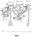
- the figure 1 partially shows in longitudinal section a low-pressure turbine of an aviation turbine engine equipped with a device according to one embodiment of the invention.
- turbomachine assembly (aeronautical or terrestrial) provided with a rotor disc having cells in which are mounted axially blade roots.
- the figure 1 represents more precisely the first stage and the second stage of the low-pressure turbine.
- the first stage consists of a mobile wheel formed of a plurality of blades 2 mounted axially on a rotor disc 4.
- the second stage consists of a distributor formed of a plurality of blades 6 and a movable wheel placed behind the dispenser and formed of a plurality of movable blades 2 'axially mounted on a rotor disc 4'.
- the rotor disks 4, 4 'of the first and second stages of the turbine are centered on the longitudinal axis XX of the turbomachine and are fixed to one another by means of bolted connections 8 regularly distributed around this axis. XX.
- Each disk 4, 4 ' has at its periphery a plurality of substantially axial cells 10, 10', open towards the outside of the disk and regularly distributed around the axis of rotation of the disks (this axis of rotation coincides with the longitudinal axis XX of the turbomachine).
- the cells are intended to receive each axially the foot 12,. 12 '(for example fir-shaped) of a moving blade 2, 2' (for example by fitting).
- Each disc 4, 4 'further comprises an annular flange 14, 14' which extends axially upstream from the upstream radial face 16, 16 'of the disc.
- This flange 14, 14 ' consists of a substantially axial annular portion 14a, 14'a extending through a substantially radial annular portion 14b, 14'b (hereinafter referred to as the free end of the disk flange).
- the disc 4 of the first stage of the turbine also comprises an annular flange 18 which extends axially downstream from the downstream radial face 20 of the disc. This flange 18 serves for fixing the disc 4 on the disk 4 'of the second stage through the bolted connections 8 as indicated above.
- annular retaining flange 22, 22 ' is mounted against the upstream radial face 16, 16' of each disc 4, 4 'with the interposition of an annular retaining ring 23, 23'.
- Each holding flange 22, 22 ' comprises an annular flange 24, 24' which extends axially upstream and which is arranged around the corresponding flange 14, 14 'of the disc.
- the flange 24, 24 'of the retaining flange consists of a substantially axial annular portion 24a, 24'a extending through a substantially radial annular portion 24b, 24'b (hereinafter referred to as the free end of flange flange).
- the holding flange 22 of the first stage of the turbine is fixed on the flange 14 of the disc 4 by means of bolted connections 26 clamping their respective free ends 24b, 14b.
- the flask of maintaining 22 'of the second stage it is fixed on the flange 14' of the disc 4 'by means of the bolted connections 8 for fixing the discs 4, 4'.
- the flange 24 of the holding flange 22 is disposed around the flange 14 of the disc so as to form therewith an annular space 28 forming a cavity for diffusing the cooling air.
- This diffusion cavity 28 is essentially formed between the axial portions 24a, 14a of the respective flanges 24, 14 of the holding flange and the disc.
- the diffusion cavity 28 opens at its downstream end into the bottom of each of the cells 10 of the disc 4 at the upstream end thereof. At its upstream end, the diffusion cavity is closed by clamping the bolted connections 26 between the free ends 24b, 14b of the respective flanges 24, 14 of the retaining flange and the disc.
- the diffusion cavity 28 is fed by a plurality of air intake orifices 30 which are regularly distributed around the longitudinal axis XX and which open into the diffusion cavity at the upstream end of it.
- these air intake orifices 30 are formed by machining in a substantially radial direction of the free end 14b of the flange 14 of the disc 4.
- these orifices could equally well be obtained by machining the end free 24b of the flange 24 of the retaining flange 22.
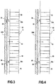
- each orifice 30 on the entire disc is variable. So, in the example of the figure 2 the angular spacing between two adjacent air intakes corresponds to about eight cavities of the disc. Thus, each orifice 30 provides cooling air to about seven cells as shown schematically by the arrows on this figure 2 .
- the air diffusion cavity 28 comprises at its downstream end means for reducing the flow of air opening into the cavities of the disc 4 which are located in the radial extension of the inlet orifices of air 30.
- cells located in the radial extension of an air intake port is meant the cell or cells which are substantially disposed in the same radial plane as each air intake port. So, in the example shown in figure 2 the cells referenced 10a correspond to the cells which are situated in the radial extension of each air intake orifice.
- the external face of the axial portion 14a of the flange 14 of the disc has at its downstream end (that is to say at the outlet of the diffusion cavity) and at each cell 10a located in the radial extension of the air intake ports 30 a boss 32.
- Such a boss 32 protrudes into the air diffusion cavity 28 and thus reduces the passage section of the air opening into these cells 10a.
- each boss 32 has a height (penetration into the diffusion cavity) H which is maximum at the cells 10a located in the radial extension of the corresponding air inlet 30 and heights h which are minimal ( or zero) at mid-angular distance between the corresponding air inlet and the two orifices directly adjacent thereto.
- the air passage section at the cells 10a located in the radial extension of the air intake orifices 30 is minimal and the air passage section at mid-angular distance between two adjacent air intakes are maximum. This corresponds perfectly to the need to increase the maximum air flow for the cells that are farthest from the air intake orifices (these cells are located at mid-angular distance between two adjacent orifices).
- each boss 32 decreases substantially evenly between its maximum height H and its minimum heights h .
- the air flow opening into each cell of the disc can be perfectly adapted to the relative angular position of the cell relative to the air intake orifices.
- each boss 32 has a profile which is substantially plane (the surfaces forming the bosses are substantially flat).
- the profile of the bosses 32 represented on the figure 4 is curvilinear, and more precisely conical (it could also be cylindrical, etc.).
- the bosses 32 are formed on the outer face of the axial portion 14a of the flange 14 of the disc.
- bosses 32 are rather formed on the inner face of the axial portion 24a of the flange 24 of the holding flange 22, these bosses of course also projecting into the diffusion cavity 28.
- Another variant not shown in the figures consists in forming the bosses both on the outer face of the flange of the disc but also on the inner face of the flange of the holding flange.
- the air intake orifices 30 are preferably arranged circumferentially between the bolted connections 26 for fixing the holding flange 22 on the flange 14 of the disc 4.
Claims (5)
- Vorrichtung zum Kühlen der Mulden einer Rotorscheibe einer Turbomaschine, umfassend:eine Rotorscheibe (4), die umfasst:an ihrem Umfang eine Vielzahl von im Wesentlichen axialen Mulden (10, 10a), die um die Rotationsachse (X-X) der Scheibe gleichmäßig verteilt sind, undeinen ringförmigen Flansch (14), der sich von einer stromaufwärtigen radialen Seite (16) der Scheibe aus stromaufwärts erstreckt,einen ringförmigen Halteflansch (22), der an der stromaufwärtigen radialen Seite der Scheibe angebracht ist und einen ringförmigen Flansch (24) umfasst, der sich stromaufwärts erstreckt und der um den Flansch (14) der Scheibe angeordnet ist und dabei mit diesem einen ringförmigen Raum (28) ausspart, welcher einen Hohlraum für die Verteilung der Kühlluft bildet, wobei dieser Verteilungshohlraum an seinem stromabwärtigen Ende in den Boden einer jeden der Mulden der Scheibe, an deren stromaufwärtigen Ende mündet, undeine Vielzahl von Luftzuführöffnungen (30), die um die Rotationsachse der Scheibe gleichmäßig verteilt sind und sich in den Verteilungshohlraum an dessen stromaufwärtigen Ende öffnen,dadurch gekennzeichnet, dass die Außenseite des Flansches (14) der Scheibe (4) und/oder die Innenseite des Flansches (24) des Halteflansches (22) an ihrem stromabwärtigen Ende und im Bereich einer jeden in der radialen Verlängerung der Luftzuführöffnungen (30) gelegenen Mulde (10a) der Scheibe einen vorspringenden Buckel (32) in dem Luftverteilungshohlraum (28) aufweist, wobei jeder Buckel (32) eine maximale Höhe (H) im Bereich der Mulden (10a) der Scheibe, die in der radialen Verlängerung der entsprechenden Luftzuführöffnung (30) gelegen sind, aufweist, so dass der Durchlassquerschnitt der Luft dort minimal ist, sowie minimale Höhen (h) auf halbem Abstand zwischen der entsprechenden Luftzuführöffnung und den beiden Öffnungen, die zu dieser direkt benachbart sind, so dass die Durchlassquerschnitte der Luft dort maximal sind.
- Vorrichtung nach Anspruch 1, bei der die Höhe eines jeden Buckels (32) zwischen seiner maximalen Höhe (H) und seinen minimalen Höhen (h) im Wesentlichen gleichmäßig abnimmt.
- Vorrichtung nach einem der Ansprüche 1 und 2, bei der jeder Buckel (32) ein im Wesentlichen ebenes oder im Wesentlichen krummliniges Profil aufweist.
- Vorrichtung nach einem der Ansprüche 1 bis 3, bei der der Halteflansch (22) an dem Flansch (14) der Scheibe (4) mittels Bolzenverbindungen (26), die deren jeweiliges freies Ende (24b, 14b) festklemmen, befestigt ist, wobei die Luftzuführöffnungen (30) zwischen den Bolzenverbindungen umfangsmäßig angeordnet sind.
- Turbomaschine, dadurch gekennzeichnet, dass sie wenigstens eine Vorrichtung zum Kühlen der Mulden einer Rotorscheibe nach einem der Ansprüche 1 bis 4 umfasst.
Applications Claiming Priority (1)
| Application Number | Priority Date | Filing Date | Title |
|---|---|---|---|
| FR0756065A FR2918103B1 (fr) | 2007-06-27 | 2007-06-27 | Dispositif de refroidissement des alveoles d'un disque de rotor de turbomachine. |
Publications (2)
| Publication Number | Publication Date |
|---|---|
| EP2009234A1 EP2009234A1 (de) | 2008-12-31 |
| EP2009234B1 true EP2009234B1 (de) | 2016-08-24 |
Family
ID=39226727
Family Applications (1)
| Application Number | Title | Priority Date | Filing Date |
|---|---|---|---|
| EP08158842.8A Active EP2009234B1 (de) | 2007-06-27 | 2008-06-24 | Kühlvorrichtung der Hohlräume einer Rotorscheibe einer Strömungsmaschine |
Country Status (7)
| Country | Link |
|---|---|
| US (1) | US8092152B2 (de) |
| EP (1) | EP2009234B1 (de) |
| JP (1) | JP5058897B2 (de) |
| CN (1) | CN101333937B (de) |
| CA (1) | CA2635636C (de) |
| FR (1) | FR2918103B1 (de) |
| RU (1) | RU2476679C2 (de) |
Families Citing this family (15)
| Publication number | Priority date | Publication date | Assignee | Title |
|---|---|---|---|---|
| FR2923525B1 (fr) * | 2007-11-13 | 2009-12-18 | Snecma | Etancheite d'un anneau de rotor dans un etage de turbine |
| FR2928963B1 (fr) * | 2008-03-19 | 2017-12-08 | Snecma | Distributeur de turbine pour une turbomachine. |
| DE102009007664A1 (de) * | 2009-02-05 | 2010-08-12 | Mtu Aero Engines Gmbh | Abdichtvorrichtung an dem Schaufelschaft einer Rotorstufe einer axialen Strömungsmaschine |
| US8382432B2 (en) * | 2010-03-08 | 2013-02-26 | General Electric Company | Cooled turbine rim seal |
| FR2961250B1 (fr) * | 2010-06-14 | 2012-07-20 | Snecma | Dispositif de refroidissement des alveoles d'un disque de rotor de turbomachine a l'aval du cone d'entrainement |
| FR2963806B1 (fr) * | 2010-08-10 | 2013-05-03 | Snecma | Dispositif de blocage d'un pied d'une aube de rotor |
| US9022727B2 (en) * | 2010-11-15 | 2015-05-05 | Mtu Aero Engines Gmbh | Rotor for a turbo machine |
| FR2973829B1 (fr) * | 2011-04-05 | 2013-05-24 | Snecma | Flasque d'etancheite pour etage de turbine de turbomachine d'aeronef, comprenant |
| EP2586968B1 (de) * | 2011-10-28 | 2019-07-10 | United Technologies Corporation | Sekundärflussanordnung für einen geschlitzten Rotor |
| US10273809B2 (en) | 2013-12-16 | 2019-04-30 | United Technologies Corporation | Centrifugal airfoil cooling modulation |
| FR3057015B1 (fr) * | 2016-09-30 | 2018-12-07 | Safran Aircraft Engines | Disque de rotor comportant une toile a epaisseur variable |
| FR3077327B1 (fr) * | 2018-01-30 | 2020-02-21 | Safran Aircraft Engines | Ensemble pour turbine de turbomachine comprenant un anneau mobile d'etancheite |
| FR3091722B1 (fr) | 2019-01-11 | 2020-12-25 | Safran Aircraft Engines | Rotor, turbine équipée d’un tel rotor et turbomachine équipée d’une telle turbine |
| FR3092612B1 (fr) * | 2019-02-12 | 2022-04-29 | Safran Aircraft Engines | Système de refroidissement d’anneau de retenue axiale d’aubes de turbine pour turbomachine d’aéronef |
| FR3093532B1 (fr) | 2019-03-06 | 2021-05-14 | Safran Aircraft Engines | Dispositif de ventilation d’une roue de turbine de turbomachine et/ou de retenue axiale d’aubes d’une telle roue |
Family Cites Families (14)
| Publication number | Priority date | Publication date | Assignee | Title |
|---|---|---|---|---|
| US2951340A (en) * | 1956-01-03 | 1960-09-06 | Curtiss Wright Corp | Gas turbine with control mechanism for turbine cooling air |
| US4021138A (en) * | 1975-11-03 | 1977-05-03 | Westinghouse Electric Corporation | Rotor disk, blade, and seal plate assembly for cooled turbine rotor blades |
| FR2732405B1 (fr) * | 1982-03-23 | 1997-05-30 | Snecma | Dispositif pour refroidir le rotor d'une turbine a gaz |
| US5018943A (en) * | 1989-04-17 | 1991-05-28 | General Electric Company | Boltless balance weight for turbine rotors |
| US5232339A (en) * | 1992-01-28 | 1993-08-03 | General Electric Company | Finned structural disk spacer arm |
| US5388962A (en) * | 1993-10-15 | 1995-02-14 | General Electric Company | Turbine rotor disk post cooling system |
| US5402636A (en) * | 1993-12-06 | 1995-04-04 | United Technologies Corporation | Anti-contamination thrust balancing system for gas turbine engines |
| US5622475A (en) * | 1994-08-30 | 1997-04-22 | General Electric Company | Double rabbet rotor blade retention assembly |
| IT1276442B1 (it) * | 1995-06-27 | 1997-10-31 | Gevipi Ag | Dispositivo di controllo della portata per un rubinetto miscelatore termostatico. |
| JP2001012205A (ja) * | 1999-06-29 | 2001-01-16 | Mitsubishi Heavy Ind Ltd | ガスタービン動翼冷却流量調整構造 |
| FR2825748B1 (fr) * | 2001-06-07 | 2003-11-07 | Snecma Moteurs | Agencement de rotor de turbomachine a deux disques aubages separes par une entretoise |
| FR2831918B1 (fr) * | 2001-11-08 | 2004-05-28 | Snecma Moteurs | Stator pour turbomachine |
| FR2867223B1 (fr) * | 2004-03-03 | 2006-07-28 | Snecma Moteurs | Turbomachine comme par exemple un turboreacteur pour avion |
| CN2833117Y (zh) * | 2005-11-04 | 2006-11-01 | 哈尔滨汽轮机厂有限责任公司 | 具有转子冷却结构的高中压合缸的超超临界汽轮机 |
-
2007
- 2007-06-27 FR FR0756065A patent/FR2918103B1/fr active Active
-
2008
- 2008-06-24 EP EP08158842.8A patent/EP2009234B1/de active Active
- 2008-06-25 US US12/145,820 patent/US8092152B2/en active Active
- 2008-06-26 CA CA2635636A patent/CA2635636C/fr active Active
- 2008-06-26 JP JP2008166895A patent/JP5058897B2/ja active Active
- 2008-06-26 RU RU2008126091/06A patent/RU2476679C2/ru active
- 2008-06-27 CN CN200810127535XA patent/CN101333937B/zh active Active
Also Published As
| Publication number | Publication date |
|---|---|
| JP5058897B2 (ja) | 2012-10-24 |
| FR2918103A1 (fr) | 2009-01-02 |
| FR2918103B1 (fr) | 2013-09-27 |
| US8092152B2 (en) | 2012-01-10 |
| CN101333937A (zh) | 2008-12-31 |
| RU2008126091A (ru) | 2010-01-10 |
| CN101333937B (zh) | 2013-03-13 |
| CA2635636A1 (fr) | 2008-12-27 |
| US20090004006A1 (en) | 2009-01-01 |
| EP2009234A1 (de) | 2008-12-31 |
| RU2476679C2 (ru) | 2013-02-27 |
| CA2635636C (fr) | 2014-11-04 |
| JP2009008086A (ja) | 2009-01-15 |
Similar Documents
| Publication | Publication Date | Title |
|---|---|---|
| EP2009234B1 (de) | Kühlvorrichtung der Hohlräume einer Rotorscheibe einer Strömungsmaschine | |
| EP2009235B1 (de) | Kühlvorrichtung für die äusseren Ausnehmungen einer Rotorscheibe einer Strömungsmaschine mit doppelter Luftzufuhr | |
| EP2366060B1 (de) | Gebläse für ein Turbotriebwerk mit einem Auswuchtsystem mit Blindlöchern zur Unterbringung von Gewichten und zugehöriges Turbotriebwerk | |
| EP1637702B1 (de) | Turbinenmodule für einen Gasturbinenmotor | |
| CA2652679C (fr) | Aubes pour roue a aubes de turbomachine avec rainure pour le refroidissement | |
| EP0789133A1 (de) | Labyrinthträgerscheibe mit einer eingebauten Versteifung für Turbomaschinenrotor | |
| EP2028375A2 (de) | Nasenhaube für eine Turbomaschine mit integrierter Auswuchtvorrichtung | |
| CA2638793A1 (fr) | Turbomachine avec diffuseur | |
| FR2968030A1 (fr) | Turbine basse-pression de turbomachine d'aeronef, comprenant un distributeur sectorise de conception amelioree | |
| EP2558729B1 (de) | Gleichrichter für eine turbomaschine | |
| FR2961250A1 (fr) | Dispositif de refroidissement des alveoles d'un disque de rotor de turbomachine a l'aval du cone d'entrainement | |
| CA2831522A1 (fr) | Flasque d'etancheite pour etage de turbine de turbomachine d'aeronef, comprenant des tenons anti-rotation fendus | |
| CA2456700C (fr) | Dispositif de refroidissement de disques de turbines | |
| FR2961249A1 (fr) | Dispositif de refroidissement des alveoles d'un disque de rotor de turbomachine | |
| EP3751102B1 (de) | Rotor für den kompressor einer rotationsmaschine und zugehöriges fertigungsverfahren | |
| EP4143421A1 (de) | Gehäuse mit zwischenflussglättung mit monoblockstrukturarm | |
| FR2971004A1 (fr) | Procede d'assemblage d'une turbine basse-pression de turboreacteur a double corps | |
| FR2928406A1 (fr) | Dispositif de retenue axiale d'aubes montees sur un disque de rotor de turbomachine, disque de rotor et flasque de maintien d'un tel dispositif | |
| FR3092865A1 (fr) | Disque de rotor avec arret axial des aubes, ensemble d’un disque et d’un anneau et turbomachine | |
| EP4010562B1 (de) | Laufschaufel für einen rotor einer flugzeugturbomaschine, rotor für eine flugzeugturbomaschine und flugzeugturbomaschine | |
| WO2020193913A1 (fr) | Aube de turbomachine equipee d'un circuit de refroidissement optimise | |
| WO2023047034A1 (fr) | Turbine à gaz haute-pression pour une turbomachine et turbomachine | |
| FR3108369A1 (fr) | Redresseur pour turbomachine d’aeronef, comprenant un limitateur de pivotement d’aube a angle de calage variable | |
| FR3116298A1 (fr) | Disque pour roue mobile de module de turbomachine d’aeronef, comprenant une butee de retention axiale d’aube integree au disque | |
| FR3087839A1 (fr) | Turbine |
Legal Events
| Date | Code | Title | Description |
|---|---|---|---|
| PUAI | Public reference made under article 153(3) epc to a published international application that has entered the european phase |
Free format text: ORIGINAL CODE: 0009012 |
|
| 17P | Request for examination filed |
Effective date: 20080624 |
|
| AK | Designated contracting states |
Kind code of ref document: A1 Designated state(s): AT BE BG CH CY CZ DE DK EE ES FI FR GB GR HR HU IE IS IT LI LT LU LV MC MT NL NO PL PT RO SE SI SK TR |
|
| AX | Request for extension of the european patent |
Extension state: AL BA MK RS |
|
| AKX | Designation fees paid |
Designated state(s): DE FR GB SE |
|
| GRAP | Despatch of communication of intention to grant a patent |
Free format text: ORIGINAL CODE: EPIDOSNIGR1 |
|
| INTG | Intention to grant announced |
Effective date: 20160315 |
|
| GRAS | Grant fee paid |
Free format text: ORIGINAL CODE: EPIDOSNIGR3 |
|
| GRAA | (expected) grant |
Free format text: ORIGINAL CODE: 0009210 |
|
| AK | Designated contracting states |
Kind code of ref document: B1 Designated state(s): DE FR GB SE |
|
| REG | Reference to a national code |
Ref country code: GB Ref legal event code: FG4D Free format text: NOT ENGLISH |
|
| REG | Reference to a national code |
Ref country code: DE Ref legal event code: R096 Ref document number: 602008045837 Country of ref document: DE |
|
| REG | Reference to a national code |
Ref country code: SE Ref legal event code: TRGR |
|
| REG | Reference to a national code |
Ref country code: FR Ref legal event code: PLFP Year of fee payment: 10 |
|
| REG | Reference to a national code |
Ref country code: DE Ref legal event code: R097 Ref document number: 602008045837 Country of ref document: DE |
|
| PLBE | No opposition filed within time limit |
Free format text: ORIGINAL CODE: 0009261 |
|
| STAA | Information on the status of an ep patent application or granted ep patent |
Free format text: STATUS: NO OPPOSITION FILED WITHIN TIME LIMIT |
|
| 26N | No opposition filed |
Effective date: 20170526 |
|
| REG | Reference to a national code |
Ref country code: FR Ref legal event code: CD Owner name: SAFRAN AIRCRAFT ENGINES, FR Effective date: 20170719 |
|
| REG | Reference to a national code |
Ref country code: FR Ref legal event code: PLFP Year of fee payment: 11 |
|
| PGFP | Annual fee paid to national office [announced via postgrant information from national office to epo] |
Ref country code: FR Payment date: 20230523 Year of fee payment: 16 Ref country code: DE Payment date: 20230523 Year of fee payment: 16 |
|
| PGFP | Annual fee paid to national office [announced via postgrant information from national office to epo] |
Ref country code: SE Payment date: 20230523 Year of fee payment: 16 |
|
| PGFP | Annual fee paid to national office [announced via postgrant information from national office to epo] |
Ref country code: GB Payment date: 20230523 Year of fee payment: 16 |