EP2008934A2 - Testverfahren mit Druckistwertrückkopplung für Kabinendruckregelungssystem - Google Patents
Testverfahren mit Druckistwertrückkopplung für Kabinendruckregelungssystem Download PDFInfo
- Publication number
- EP2008934A2 EP2008934A2 EP08158862A EP08158862A EP2008934A2 EP 2008934 A2 EP2008934 A2 EP 2008934A2 EP 08158862 A EP08158862 A EP 08158862A EP 08158862 A EP08158862 A EP 08158862A EP 2008934 A2 EP2008934 A2 EP 2008934A2
- Authority
- EP
- European Patent Office
- Prior art keywords
- pressure
- cabin
- signal
- control system
- aircraft
- Prior art date
- Legal status (The legal status is an assumption and is not a legal conclusion. Google has not performed a legal analysis and makes no representation as to the accuracy of the status listed.)
- Granted
Links
- 238000010998 test method Methods 0.000 title 1
- 238000012360 testing method Methods 0.000 claims abstract description 50
- 230000004044 response Effects 0.000 claims description 6
- 238000000034 method Methods 0.000 description 11
- 238000011156 evaluation Methods 0.000 description 7
- 238000010586 diagram Methods 0.000 description 5
- 230000033001 locomotion Effects 0.000 description 5
- 230000007423 decrease Effects 0.000 description 4
- 230000008901 benefit Effects 0.000 description 3
- 238000012986 modification Methods 0.000 description 3
- 230000004048 modification Effects 0.000 description 3
- 238000005094 computer simulation Methods 0.000 description 2
- 230000001276 controlling effect Effects 0.000 description 2
- 230000002411 adverse Effects 0.000 description 1
- 238000004364 calculation method Methods 0.000 description 1
- 230000008859 change Effects 0.000 description 1
- 230000002596 correlated effect Effects 0.000 description 1
- 238000011161 development Methods 0.000 description 1
- 230000000694 effects Effects 0.000 description 1
- 230000010006 flight Effects 0.000 description 1
- 238000010348 incorporation Methods 0.000 description 1
- 230000003584 silencer Effects 0.000 description 1
- 238000004088 simulation Methods 0.000 description 1
Images


Classifications
-
- B—PERFORMING OPERATIONS; TRANSPORTING
- B64—AIRCRAFT; AVIATION; COSMONAUTICS
- B64F—GROUND OR AIRCRAFT-CARRIER-DECK INSTALLATIONS SPECIALLY ADAPTED FOR USE IN CONNECTION WITH AIRCRAFT; DESIGNING, MANUFACTURING, ASSEMBLING, CLEANING, MAINTAINING OR REPAIRING AIRCRAFT, NOT OTHERWISE PROVIDED FOR; HANDLING, TRANSPORTING, TESTING OR INSPECTING AIRCRAFT COMPONENTS, NOT OTHERWISE PROVIDED FOR
- B64F5/00—Designing, manufacturing, assembling, cleaning, maintaining or repairing aircraft, not otherwise provided for; Handling, transporting, testing or inspecting aircraft components, not otherwise provided for
- B64F5/60—Testing or inspecting aircraft components or systems
Definitions
- the present invention is in the field of systems that control pressure within enclosures and, more particularly, in the field of testing of pressure control systems which operate in vehicles such as aircraft.
- cabin-pressure control systems that maintains a cabin pressure at tolerable levels irrespective of actual atmospheric pressure at the altitude in which the aircraft may be operating.
- Cabin-pressure control systems must have a capability of continuously modifying cabin pressure relative to atmospheric pressure.
- cabin pressure must progressively change from ground level pressure to a desired cabin pressure, e.g. a pressure that corresponds to an altitude of about 8000 ft above sea level.
- relative cabin pressure i.e. cabin pressure relative to external atmospheric pressure
- the actual internal pressure of the cabin must remain at the 8000 ft. pressure.
- the relative cabin pressure must continuously decrease to reduce the cabin altitude to the ground level pressure for when the aircraft lands. During this time, the absolute cabin pressure is increasing.
- a cabin-pressure control must be constructed and tailored to operate correctly within a particular aircraft configuration. Aircraft configurations continually evolve. Consequently, cabin-pressure control systems must evolve correspondingly. Also, continuing effort is directed to improving the efficiency and accuracy of cabin-pressure controls systems. Both of these factors produce a need for evaluating the effectiveness of newly designed or newly modified cabin-pressure systems before they are actually incorporated into an operating aircraft.
- altitude chambers In the prior art, such evaluation is performed in large altitude chambers. Such a chamber must be large enough to accommodate an aircraft cabin.
- the altitude chamber must be provided with a vacuum system that produces a reduced pressure at an exterior of the cabin to simulate high altitude flight.
- Altitude chambers are expensive to build and expensive to operate.
- outflow valves are large structures that may be incorporated into a body of the aircraft. In some cases the outflow valves may be motor driven or driven by hydraulic or pneumatic actuators.
- a method for testing a system for controlling pressure in an enclosure may comprise the steps of producing a first electrical signal to simulate pressure of an enclosure and producing a pneumatic signal that corresponds to the electrical signal.
- a pressure control system that is being tested is operated responsively to the pneumatic signal.
- a second electrical signal is produced responsively to the operation of the pressure control system and the second electrical signal is used to determine if the pressure-control system functions correctly.
- a method for testing an aircraft cabin-pressure control system comprises the steps of simulating cabin-pressure, producing an electrical cabin-pressure signal and converting the electrical cabin-pressure signal to a pneumatic cabin-pressure signal.
- a controller of the cabin-pressure control system is operated responsively to the pneumatic cabin-pressure signal.
- An electric feedback is produced responsively to operation of the control system to provide closed-loop testing of the cabin-pressure control system.
- an apparatus for performing testing of an aircraft cabin-pressure control system comprises a self-contained transducer for converting the electrical cabin-pressure signal to a pneumatic cabin-pressure signal.
- the transducer comprises a proportioning valve to receive an electrical pressure signal, a jet pump for producing vacuum in the proportioning valve, an inlet for positively pressurized air; and an outlet for a pneumatic pressure signal.
- Figure 1 is a block diagram of a system for testing a pressure-control system in accordance with the present invention
- FIG. 2 is a block diagram of a voltage-to-pressure transducer in accordance with the invention.
- FIG. 3 is a block diagram of an alternate exemplary embodiment of the system of Figure 1 in accordance with the present invention.
- Figure 4 is a perspective view of an aerodynamic load and valve simulator in accordance with the invention.
- Figure 5 is a flow chart of a method for testing a pressure-control system in accordance with the present invention.
- Figure 6 is a flow chart of alternate embodiment of a method for testing a pressure-control system in accordance with the present invention.
- the present invention may be useful in evaluating and testing pressure control systems. More particularly, the present invention may provide for evaluation and testing of cabin-pressure control systems of aircraft. The present invention may be particularly useful for bench testing of cabin-pressure control systems prior to incorporation of the systems into an aircraft.
- the present invention may employ a cabin-pressure simulator coupled to a voltage-to-pressure transducer to provide a pneumatic pressure signal that is transmitted to the control system being tested.
- the control system may respond to the pneumatic pressure signal and command movement of an outflow-valve actuator.
- the actuator may produce an electrical feed-back signal to the pressure simulator, which simulator may, in turn, respond to the feedback signal. Closed-loop testing may thus be performed on the control system without use of an altitude chamber.
- the testing system 10 may comprise a cabin pressure simulator 12, a monitor 13, a voltage-to-pressure transducer 14, a potentiometer 16 and a modeling processor 18.
- the cabin pressure simulator 12 may be provided with detailed aircraft configuration data from the modeling processor 18 via an interconnection 18a.
- the modeling processor 18 may also provide data to the simulator 12 that defines expected or specified performance characteristics of the control system 10. By way of example, this data may be provided in digital format.
- the cabin-pressure simulator 12 may produce a cabin pressure output signal 12a that is correlated with the aircraft configuration data.
- the signal 12a may be provided in an analog or digital format.
- the signal 12a may be processed in the voltage-to-pressure transducer 14.
- the transducer 14 may produce a pneumatic signal 14a.
- the signal 14a may be provided as an increase or decrease of air pressure in an output connector 14b.
- the pneumatic signal 14a may be very sensitive. In order to proper simulate actual cabin pressure response the signal 12a may be produced by simulator 12 with a 16-bit or better resolution. This may preclude generation of pressure steps that could cause inadvertent overdrive of the cabin pressure controller 20,
- the connector 14b may be attached to a controller of a cabin-pressure system that is to be evaluated or tested.
- the control system to be tested is designated by the numeral 19.
- the control system 19 may comprise a controller 20 and an outflow valve actuator 22.
- the controller 20 may be interconnected with the actuator 22 so that the actuator 22 may respond to an actuator signal 20a from the controller 20.
- the actuator signal 20a may be electrical, pneumatic or hydraulic depending on the nature of the control system 20 and the actuator 22.
- the controller 20 may communicate with monitor 13, via 20b, for insight into actual calculations and logic steps that the controller 20 may be performing. This has the advantage of allowing improvements to be made during the development of the system.
- the actuator 22 may be mechanically connected to the potentiometer 16, or a similar rotary or linear position sensor of adequate output resolution, with a mechanical connector or drive shaft 22b. As the actuator 22 moves in response to the actuator signal 20a, its motion may vary a potentiometer signal 16a.
- the signal 16a may be received by the cabin-pressure simulator 12 and thus complete a closed control loop.
- at least 16-bits of analog-to-digital data may be required by pressure simulator 12 to ensure that the pneumatic output response is not producing inordinately large pressure steps. The pressure steps should not exceed an actual cabin pressure response would may occur in a cabin of an actual airplane.
- the potentiometer 16 may be considered a detector for operations of the actuator 22.
- the simulator 12 may increase or decrease the signal 12a if the potentiometer signal 16a is indicative of a changing response of the controller 20 and the actuator 22. Variations in the signal 12a may be viewed with the modeling processor 18 with a signal 18b and then forwarded to the monitor 13, with a signal 13a, for comparison against known expected results and performance evaluation.
- the transducer 14 may comprise a proportional control valve 142 which may be interconnected to laboratory power (not shown) with an AC to DC converter 144.
- a jet pump 146 may produce vacuum (i.e. negative pressure relative to atmospheric pressure) and provide the vacuum to the proportioning valve 142.
- the jet pump 146 may produce vacuum, via "venturi effect", by an external source (not shown) of highpressure air delivered through a regulator 148 to an inlet of 146.
- the highpressure air may also be delivered to the proportioning valve 142 through a regulator 150.
- Gauges 148a and 150a may be provided to monitor output pressures of the regulators 148 and 150 respectively.
- a control signal e.g. the signal 12a of Figure 1
- the proportioning valve 142 may produce a pneumatic output signal, e.g., the signal 14a of Figure 1 with a correspondingly high 16 bit resolution.
- the valve 142 may combine positively pressurized air provided to an inlet 150b of the regulator 150, vacuum from the jet pump 146, electrical power from the converter 144 and the signal 12a to produce a pneumatic pressure signal (e.g., the signal 14a of Figure 1 ).
- the transducer 14 may be provided with other control elements, for example, a volume tank 152, with a capacity of about 150 cubic centimeters, may be provided for reducing high-frequency pressure transients.
- a three-way valve 154 may be employed to allow a selective determination of whether or not the volume tank should be employed.
- a needle valve 156 may be employed to ensure a continuous flow of air to the jet pump 146 from the valve 142.
- the transducer 14 may be self-contained and readily adapted for bench testing operations. Electrical power to the transducer may be provided from a conventional 115 volts AC power source.
- the transducer 14 may be enclosed within a portable cabinet or case 160.
- the jet pump 146 may be provided with a silencer 146a to enhance working conditions in the vicinity of the transducer 14.
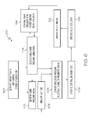
- a cabin-pressure testing system is designated generally by the numeral 200.
- the system 200 may comprise the cabin pressure simulator 12, the monitor 13, a voltage-to-pressure transducer 214, an altitude simulator 215, the potentiometer 16 and the modeling processor 18.
- the cabin pressure simulator 12 may be provided with detailed aircraft configuration data from the modeling processor 18. In operation, the cabin pressure simulator 12 may also be provided with actuator 22 rotational position feedback 16a.
- the cabin-pressure simulator 12 may produce a cabin pressure output signal 12a and an altitude simulator 215 may produce an altitude signal 215a.
- the signals 12a and 215a may be processed in the voltage-to-pressure transducer 214.
- the transducer may produce two pneumatic signals 214a c and 214a a .
- the signal 214a c and 214a a may be provided as increases or decreases of air pressure in output connector 214b c and 214b a respectively. It may be seen that the testing system 200 may perform testing on one of the control systems to be tested.
- control system is designated generally by the numeral 219.
- the control system 219 may require both cabin pressure and altitude inputs for proper operation.
- the testing system 200 may function in the same manner as the testing system 10 of Figure 1 .
- the testing systems 10 and 200 of the present invention may perform testing on many possible configurations of the controllers 20 and the actuators 22.
- FIG. 4 it may be seen how the inventive testing systems 10 and 200 may provide testing and evaluation of one of the control systems 19 even if its associated outflow valves are not present in the test.
- An aerodynamic load and outflow valve simulator 300 is shown attached to an exemplary one of the outflow-valve actuators 22.
- the aerodynamic load and outflow valve simulator 300 may comprise a support 302, a torsion spring 304, an adjusting plate 306 and a spring attachment plate 308.
- the aerodynamic load and outflow valve simulator 300 may provide torsion on the actuator 22 during operation of the actuator 22.
- This torsion may simulate the aerodynamic load conditions that exist in an operating aircraft.
- airflow may produce continuous back-pressure forces (e.g., aerodynamic loads) on vanes of the outflow valve (not shown).
- aerodynamic loads forces e.g., aerodynamic loads
- the actuator 22 may continuously drive against a mechanical load.
- the actuator 22 may not experience backlash.
- accuracy of testing would be adversely affected. This is because the actuator 22 under test may not operate in a manner that accurately simulates in-flight conditions.
- a 10 degree command may produce a net forward rotation of only 8 degrees (a commanded 10 degrees minus a 2 degree backlash). If, on the other hand, backlash were prevented during the test, then the 10 degree command may produce an actual 10 degree rotation just as it would in an in-flight aircraft.
- valve simulator 300 may provide this desirable functionality.
- the aerodynamic load and outflow valve simulator 300 may be attached to the actuator 22.
- the drive shaft 22b of the actuator may be positioned within the support 302.
- the drive shaft 22b may be free to rotate relative to the support 302.
- Drive shaft 22b may be engaged with valve simulator 300 via valve simulator shaft 310.
- a spring attachment plate 308 may be engaged with the valve simulator shaft 310.
- a first end 304a of the torsion spring 304 may be attached to the plate 308.
- a second end 304b of the torsion spring may be attached to the adjusting plate 306.
- the adjusting plate 306 may be adjustably located relative to the support 302 with fasteners 306a and slotted holes 306b.
- the torsion spring 304 may produce a continuous closing torque on the shaft 310.
- the closing torque may be present whether or not the shafts 22b and 310 may be rotating. Thus, backlash of the shaft 22b may be eliminated. It is important that the adjusting plate 306 is properly positioned so that the torsion spring 304 does not produce excessive torque, beyond the actual torque expected in actual flight that may cause backward motion of the shaft 22b.
- the adjusting plate 306 may require re-positioning for different types of the actuators 22.
- valve simulator shaft 310 Fixed to valve simulator shaft 310 is position sensor (e.g. the potentiometer 16 of Figure 1 ).
- the potentiometer 16 may also be rotationally fixed to actuator shaft 22b. Referring to Figures 1 and 3 , it may be seen that rotational output of actuator 22 may be mechanically transferred to the potentiometer 16 to provide an accurate signal 16a to pressure simulator 12.
- a method may be provided for testing systems that may control pressure not only in aircraft cabins but in many other types of enclosures, such as buildings or portions of buildings e.g. "clean rooms".
- the method may be understood by referring to Figure 5 .
- Figure 5 a flow chart portrays various aspects of an inventive method 400.
- configuration data of an enclosure may be generated (e.g. by the modeling processor 18).
- a first simulated enclosure-pressure signal may be generated (e.g. the electrical signal 12a may be generated by the cabin pressure simulator 12).
- the electrical signal of step 404 may be converted into a pneumatic signal (e.g. the signal 14a produced by the voltage-to-pressure transducer 14).
- a pressure controller under test (e.g. the cabin pressure controller 20) may be operated responsively to the pneumatic signal produced in step 406.
- a valve actuator may be operated (e.g. the actuator 22 may be operated responsively to the signal 20a produced by the controller 20).
- a potentiometer may be operated by the valve actuator (e.g. the potentiometer 16 may be operated by motion of the actuator 22 through the mechanical connector 22b).
- an electrical signal may be generated and transmitted to a comparison step 414.
- comparison may be made of the signal from step 412 with the signal from step 404 and data from the step 402.
- the simulator may generate a second enclosure-pressure signal at a magnitude that may be determined in the step 414.
- the steps 404 through 414 may be performed repeatedly so that a continuum of signals may be provided for a closed-loop testing of the pressure control system under test.
- the enclosure-pressure signal may be continuously monitored and compared to a signal from the modeling processor which performs the step 402. In this manner, operating characteristics of the control system under test may be observed.
- a method for testing a system for controlling pressure in a vehicle or a portion of a vehicle, for example, an aircraft cabin.
- the method may be understood by referring to Figure 6 .
- Figure 6 a flow chart portrays various aspects of an inventive method 500.
- aircraft configuration data may be generated (e.g. by the modeling processor 18).
- a simulated cabin pressure signal may be generated (e.g. the electrical signal 12a may be generated by the cabin pressure simulator 12).
- an electrical altitude simulation signal may be produced (e.g. the signal 215a may be produced by the altitude simulator 215).
- the electrical signals of steps 504 and 505 may be converted into pneumatic signals (e.g. the signal 214a c and 214a a produced by the voltage-to-pressure transducer 214).
- a pressure controller under test (e.g. the cabin pressure controller 20) may be operated responsively to the pneumatic signals produced in step 506.
- a valve actuator may be operated (e.g. the actuator 22 may be operated responsively to the signal 20a produced by the control system 20).
- a potentiometer may be operated by the valve actuator (e.g. the potentiometer 16 may be operated by motion of the actuator 22 through the mechanical connector 22b.
- an electrical signal may be generated and transmitted to a comparison step 514 in which the signal from the step 512 may be compared with the signal from the step 504 and with data from the step 502.
- Completion of the steps 504 through 514 may thus provide a closed-loop test of the pressure control system under test in the manner described above with respect to the method 400.
- the cabin pressure signal may be monitored to observe operating characteristics of the control system under test may be observed.
Landscapes
- Engineering & Computer Science (AREA)
- Manufacturing & Machinery (AREA)
- Transportation (AREA)
- Aviation & Aerospace Engineering (AREA)
- Testing Of Devices, Machine Parts, Or Other Structures Thereof (AREA)
- Measuring Fluid Pressure (AREA)
Applications Claiming Priority (2)
| Application Number | Priority Date | Filing Date | Title |
|---|---|---|---|
| US94619107P | 2007-06-26 | 2007-06-26 | |
| US11/940,151 US7686680B2 (en) | 2007-06-26 | 2007-11-14 | Closed-loop cabin pressure control system test method with actual pressure feedback |
Publications (3)
| Publication Number | Publication Date |
|---|---|
| EP2008934A2 true EP2008934A2 (de) | 2008-12-31 |
| EP2008934A3 EP2008934A3 (de) | 2011-05-18 |
| EP2008934B1 EP2008934B1 (de) | 2013-04-24 |
Family
ID=39791220
Family Applications (1)
| Application Number | Title | Priority Date | Filing Date |
|---|---|---|---|
| EP08158862.6A Not-in-force EP2008934B1 (de) | 2007-06-26 | 2008-06-24 | Testverfahren mit Druckistwertrückkopplung für Kabinendruckregelungssystem |
Country Status (2)
| Country | Link |
|---|---|
| US (1) | US7686680B2 (de) |
| EP (1) | EP2008934B1 (de) |
Cited By (4)
| Publication number | Priority date | Publication date | Assignee | Title |
|---|---|---|---|---|
| FR2953494A1 (fr) * | 2009-12-08 | 2011-06-10 | Goodrich Actuation Systems Sas | Dispositif de test de la detection de la reprise effort par une voie secondaire d'un actionneur de commande de vol, et procede de test associe |
| CN102331784A (zh) * | 2011-07-15 | 2012-01-25 | 上海交通大学 | 飞机前起落架装配前调姿定位在线调整系统及其方法 |
| CN102436258A (zh) * | 2011-12-06 | 2012-05-02 | 上海交通大学 | 用于民用飞机环境控制系统座舱功能试验的自动化装置 |
| CN110182384A (zh) * | 2019-05-27 | 2019-08-30 | 西北工业大学 | 电气系统显示模拟器和方法及飞机电力系统综合测试系统 |
Families Citing this family (14)
| Publication number | Priority date | Publication date | Assignee | Title |
|---|---|---|---|---|
| DE102004017950B3 (de) * | 2004-04-14 | 2005-06-23 | Moeller Gmbh | Mechanisch-elektronischer Positionsgeber |
| US20070085907A1 (en) * | 2005-10-14 | 2007-04-19 | Smiths Aerospace Llc | Video storage uplink system |
| US8694181B2 (en) | 2012-03-12 | 2014-04-08 | Honeywell International Inc. | Cabin pressure control system with multiple outflow valves and method of calibrating the outflow valve position feedback during flight |
| CA2919342C (en) | 2015-04-15 | 2023-08-15 | Goodrich Actuation Systems Sas | Check device for flight actuator primary load path failure detection device |
| CN105547364B (zh) * | 2015-12-23 | 2017-11-24 | 南京航空航天大学 | 路基内部监测的拼接型分布式光纤传感系统 |
| CN106249731B (zh) * | 2016-06-29 | 2020-04-14 | 山东首景辉光电科技有限公司 | 一种军用飞机座舱压力调节系统外场检测装置 |
| CN106706236A (zh) * | 2016-12-28 | 2017-05-24 | 中国航空工业集团公司西安飞机设计研究所 | 一种座舱气密试验器 |
| US10988262B2 (en) * | 2018-03-14 | 2021-04-27 | Honeywell International Inc. | Cabin pressure control system architecture using cabin pressure air for inlet to APU core compressor |
| DE102019126091B4 (de) * | 2019-09-27 | 2024-06-20 | Airbus Operations Gmbh | Verfahren zur Funktionsprüfung eines Ablassventils an einem Flugzeugrumpf |
| CN110749434B (zh) * | 2019-11-26 | 2025-04-04 | 四川大学 | 取芯器保压舱保压特性试验系统及方法 |
| CN111721478A (zh) * | 2020-06-05 | 2020-09-29 | 中国航空工业集团公司上海航空测控技术研究所 | 航空器用气密性检查系统 |
| CN111721480B (zh) * | 2020-06-29 | 2021-07-20 | 南京航空航天大学 | 一种基于飞行数据的民机机组氧气系统渗漏预警方法 |
| CN117302547A (zh) * | 2023-11-15 | 2023-12-29 | 中航通飞华南飞机工业有限公司 | 一种水陆两栖飞机起落架泥沙水冲击验证试验方法 |
| EP4596411A1 (de) * | 2024-02-05 | 2025-08-06 | Honeywell International Inc. | System zum testen eines kabinendruckregelsystems |
Citations (1)
| Publication number | Priority date | Publication date | Assignee | Title |
|---|---|---|---|---|
| US20040238039A1 (en) | 2003-05-29 | 2004-12-02 | Friedrichs Hans Peter | Pneumatic generator system for simulating operating conditions of an aircraft |
Family Cites Families (21)
| Publication number | Priority date | Publication date | Assignee | Title |
|---|---|---|---|---|
| US3039206A (en) * | 1959-06-02 | 1962-06-19 | Gen Precision Inc | Cabin pressurization system |
| US3376803A (en) * | 1966-07-11 | 1968-04-09 | United Aircraft Corp | Cabin pressure regulator |
| US3577902A (en) * | 1968-11-14 | 1971-05-11 | United Aircraft Corp | Digital integrator |
| US4086804A (en) * | 1976-10-26 | 1978-05-02 | Sperry Rand Corporation | Precision pneumatic pressure supply system |
| DE4316886C2 (de) * | 1993-05-19 | 1995-05-18 | Nord Micro Elektronik Feinmech | Kabinendruckregelanlage für Flugzeuge |
| US7131136B2 (en) * | 2002-07-10 | 2006-10-31 | E-Watch, Inc. | Comprehensive multi-media surveillance and response system for aircraft, operations centers, airports and other commercial transports, centers and terminals |
| BRPI0106953B1 (pt) * | 2000-07-20 | 2016-03-22 | Nord Micro Ag & Co Ohg | controlador, sistema regulador da pressão de cabine e processo de controlar a pressão da cabine |
| US20020130220A1 (en) * | 2001-03-13 | 2002-09-19 | Bob Sparks | Airships having simplied construction and improved maneuverability |
| US6790041B2 (en) * | 2001-09-05 | 2004-09-14 | Fountain & Associates, Inc. | Training methods for aircraft simulator pilot |
| AU2002334708A1 (en) * | 2001-10-01 | 2003-04-14 | Kline And Walker, Llc | Pfn/trac system faa upgrades for accountable remote and robotics control |
| US6737988B2 (en) * | 2002-02-21 | 2004-05-18 | Honeywell International, Inc. | Instrumentation and control circuit having multiple, dissimilar sources for supplying warnings, indications, and controls and an integrated cabin pressure control system valve incorporating the same |
| US6532800B1 (en) * | 2002-04-16 | 2003-03-18 | Thunder Aviation Na, Inc. | Aircraft pressurization test apparatus and method of using same |
| US6979257B2 (en) * | 2004-01-14 | 2005-12-27 | Honeywell International, Inc. | Cabin pressure control method and apparatus using all-electric control without outflow valve position feedback |
| US20060019594A1 (en) * | 2004-07-22 | 2006-01-26 | Honeywell International, Inc. | Cabin pressure control system and method |
| US7008314B2 (en) * | 2004-08-02 | 2006-03-07 | Honeywell International, Inc. | Aircraft modular cabin pressure regulator |
| WO2006028980A2 (en) * | 2004-09-01 | 2006-03-16 | Humphries Peter J | Space manufacturing module system and method |
| US7176811B1 (en) * | 2005-03-07 | 2007-02-13 | The United States Of America As Represented By The Secretary Of The Air Force | Pressure altimeter electrical testing |
| US20070078618A1 (en) * | 2005-09-30 | 2007-04-05 | Honeywell International, Inc. | Method and system for enabling automated data analysis of multiple commensurate nondestructive test measurements |
| US7624943B2 (en) * | 2006-03-22 | 2009-12-01 | The Boeing Company | Multi-mode unmanned and manned vehicle systems and methods |
| US7658669B2 (en) * | 2007-02-09 | 2010-02-09 | Honeywell International Inc. | Aircraft cabin pressure controls with an open-loop motor control system: non-linear control law logic to compensate for excessive motor loads or motor degradation |
| US8808072B2 (en) * | 2007-03-22 | 2014-08-19 | Honeywell International Inc. | Cabin pressure control system dual valve control and monitoring architecture |
-
2007
- 2007-11-14 US US11/940,151 patent/US7686680B2/en not_active Expired - Fee Related
-
2008
- 2008-06-24 EP EP08158862.6A patent/EP2008934B1/de not_active Not-in-force
Patent Citations (1)
| Publication number | Priority date | Publication date | Assignee | Title |
|---|---|---|---|---|
| US20040238039A1 (en) | 2003-05-29 | 2004-12-02 | Friedrichs Hans Peter | Pneumatic generator system for simulating operating conditions of an aircraft |
Cited By (6)
| Publication number | Priority date | Publication date | Assignee | Title |
|---|---|---|---|---|
| FR2953494A1 (fr) * | 2009-12-08 | 2011-06-10 | Goodrich Actuation Systems Sas | Dispositif de test de la detection de la reprise effort par une voie secondaire d'un actionneur de commande de vol, et procede de test associe |
| EP2332838A1 (de) * | 2009-12-08 | 2011-06-15 | Goodrich Actuation Systems SAS | Testvorrichtung zur Erfassung der Wiederherstellung des Drucks über eine Nebenleitung eines Stellglieds zur Flugsteuerung, und entsprechendes Testverfahren |
| CN102331784A (zh) * | 2011-07-15 | 2012-01-25 | 上海交通大学 | 飞机前起落架装配前调姿定位在线调整系统及其方法 |
| CN102331784B (zh) * | 2011-07-15 | 2013-05-01 | 上海交通大学 | 飞机前起落架装配前调姿定位在线调整系统及其方法 |
| CN102436258A (zh) * | 2011-12-06 | 2012-05-02 | 上海交通大学 | 用于民用飞机环境控制系统座舱功能试验的自动化装置 |
| CN110182384A (zh) * | 2019-05-27 | 2019-08-30 | 西北工业大学 | 电气系统显示模拟器和方法及飞机电力系统综合测试系统 |
Also Published As
| Publication number | Publication date |
|---|---|
| EP2008934B1 (de) | 2013-04-24 |
| US7686680B2 (en) | 2010-03-30 |
| US20090006056A1 (en) | 2009-01-01 |
| EP2008934A3 (de) | 2011-05-18 |
Similar Documents
| Publication | Publication Date | Title |
|---|---|---|
| EP2008934B1 (de) | Testverfahren mit Druckistwertrückkopplung für Kabinendruckregelungssystem | |
| Karpenko et al. | Hardware-in-the-loop simulator for research on fault tolerant control of electrohydraulic actuators in a flight control application | |
| US8849603B2 (en) | Systems and methods for control system verification and health assessment | |
| EP2762852A1 (de) | Selbstprüfungssystem für eine Gasturbine | |
| CN101321667A (zh) | 用于重构飞行器、尤其是客机上的阵风和结构载荷的方法 | |
| Busan et al. | Enabling Advanced Wind-Tunnel Research Methods Using the NASA Langley 12-Foot Low Speed Tunnel | |
| KR20140140279A (ko) | 회전익 항공기 미부 공력진동 예측시스템 및 그 제어방법 | |
| Ahmad et al. | Dynamic modelling and linear quadratic Gaussian control of a twin-rotor multi-input multi-output system | |
| Jacazio et al. | Real-time loading actuator control for an advanced aerospace test rig | |
| Du Val et al. | FLIGHTLAB TM modeling for real-time simulation applications | |
| CN113252286A (zh) | 一种飞行器复合控制风洞半实物仿真试验系统 | |
| Wang et al. | Model based design and procedure of flight control system for unmanned aerial vehicle | |
| Scott et al. | Aeroservoelastic wind-tunnel test of the SUGAR truss braced wing wind-tunnel model | |
| CN201732032U (zh) | 汽车座椅疲劳耐久测试系统 | |
| CN113050583A (zh) | 一种飞行控制系统地面测试平台及其测试方法 | |
| Rachman et al. | Non-linear simulation of controller for longitudinal control augmentation system of F-16 using numerical approach | |
| US20220163490A1 (en) | Methods and Devices of Detecting Frictional Interference of a Mechanical Component Within a Vehicle | |
| Scott et al. | Aeroservoelastic test of the subsonic ultra-green aircraft research truss-braced wing model | |
| Wei et al. | Helicopter Flight Test Data Simulation Using CCSU Flight Simulator | |
| Harris et al. | Model Following Control Allocation For The X-62A | |
| Lepage et al. | Wind tunnel tests for gust load investigation in transonic flows–part 1: development of an innovative test rig | |
| Avanzini et al. | Modelling and simulation of a shrouded-fan uav for environmental monitoring | |
| Kandias | Experimental Scaling of Hovering Rotorcraft Aerodynamics in Hyperbaric Conditions | |
| Trainelli et al. | Development and testing of innovative solutions for helicopter in-flight noise monitoring and enhanced control based on rotor state measurements | |
| Leyden et al. | Highly Interchangeable Carrier Landing Analysis and Simulation (HI-CLAS) Software for Control Systems |
Legal Events
| Date | Code | Title | Description |
|---|---|---|---|
| PUAI | Public reference made under article 153(3) epc to a published international application that has entered the european phase |
Free format text: ORIGINAL CODE: 0009012 |
|
| 17P | Request for examination filed |
Effective date: 20080624 |
|
| AK | Designated contracting states |
Kind code of ref document: A2 Designated state(s): AT BE BG CH CY CZ DE DK EE ES FI FR GB GR HR HU IE IS IT LI LT LU LV MC MT NL NO PL PT RO SE SI SK TR |
|
| AX | Request for extension of the european patent |
Extension state: AL BA MK RS |
|
| PUAL | Search report despatched |
Free format text: ORIGINAL CODE: 0009013 |
|
| AK | Designated contracting states |
Kind code of ref document: A3 Designated state(s): AT BE BG CH CY CZ DE DK EE ES FI FR GB GR HR HU IE IS IT LI LT LU LV MC MT NL NO PL PT RO SE SI SK TR |
|
| AX | Request for extension of the european patent |
Extension state: AL BA MK RS |
|
| 17Q | First examination report despatched |
Effective date: 20110502 |
|
| AKX | Designation fees paid |
Designated state(s): DE FR GB |
|
| GRAP | Despatch of communication of intention to grant a patent |
Free format text: ORIGINAL CODE: EPIDOSNIGR1 |
|
| GRAS | Grant fee paid |
Free format text: ORIGINAL CODE: EPIDOSNIGR3 |
|
| GRAA | (expected) grant |
Free format text: ORIGINAL CODE: 0009210 |
|
| AK | Designated contracting states |
Kind code of ref document: B1 Designated state(s): DE FR GB |
|
| REG | Reference to a national code |
Ref country code: GB Ref legal event code: FG4D |
|
| REG | Reference to a national code |
Ref country code: DE Ref legal event code: R096 Ref document number: 602008024012 Country of ref document: DE Effective date: 20130620 |
|
| PLBE | No opposition filed within time limit |
Free format text: ORIGINAL CODE: 0009261 |
|
| STAA | Information on the status of an ep patent application or granted ep patent |
Free format text: STATUS: NO OPPOSITION FILED WITHIN TIME LIMIT |
|
| 26N | No opposition filed |
Effective date: 20140127 |
|
| REG | Reference to a national code |
Ref country code: DE Ref legal event code: R097 Ref document number: 602008024012 Country of ref document: DE Effective date: 20140127 |
|
| REG | Reference to a national code |
Ref country code: FR Ref legal event code: PLFP Year of fee payment: 8 |
|
| PGFP | Annual fee paid to national office [announced via postgrant information from national office to epo] |
Ref country code: GB Payment date: 20150526 Year of fee payment: 8 |
|
| PGFP | Annual fee paid to national office [announced via postgrant information from national office to epo] |
Ref country code: FR Payment date: 20150528 Year of fee payment: 8 |
|
| PGFP | Annual fee paid to national office [announced via postgrant information from national office to epo] |
Ref country code: DE Payment date: 20150630 Year of fee payment: 8 |
|
| REG | Reference to a national code |
Ref country code: DE Ref legal event code: R119 Ref document number: 602008024012 Country of ref document: DE |
|
| GBPC | Gb: european patent ceased through non-payment of renewal fee |
Effective date: 20160624 |
|
| REG | Reference to a national code |
Ref country code: FR Ref legal event code: ST Effective date: 20170228 |
|
| PG25 | Lapsed in a contracting state [announced via postgrant information from national office to epo] |
Ref country code: DE Free format text: LAPSE BECAUSE OF NON-PAYMENT OF DUE FEES Effective date: 20170103 Ref country code: FR Free format text: LAPSE BECAUSE OF NON-PAYMENT OF DUE FEES Effective date: 20160630 |
|
| PG25 | Lapsed in a contracting state [announced via postgrant information from national office to epo] |
Ref country code: GB Free format text: LAPSE BECAUSE OF NON-PAYMENT OF DUE FEES Effective date: 20160624 |
|
| P01 | Opt-out of the competence of the unified patent court (upc) registered |
Effective date: 20230525 |