EP2008841A1 - Automotive air conditioner - Google Patents
Automotive air conditioner Download PDFInfo
- Publication number
- EP2008841A1 EP2008841A1 EP08159123A EP08159123A EP2008841A1 EP 2008841 A1 EP2008841 A1 EP 2008841A1 EP 08159123 A EP08159123 A EP 08159123A EP 08159123 A EP08159123 A EP 08159123A EP 2008841 A1 EP2008841 A1 EP 2008841A1
- Authority
- EP
- European Patent Office
- Prior art keywords
- air
- door
- warm air
- foot
- warm
- Prior art date
- Legal status (The legal status is an assumption and is not a legal conclusion. Google has not performed a legal analysis and makes no representation as to the accuracy of the status listed.)
- Granted
Links
Images



Classifications
-
- B—PERFORMING OPERATIONS; TRANSPORTING
- B60—VEHICLES IN GENERAL
- B60H—ARRANGEMENTS OF HEATING, COOLING, VENTILATING OR OTHER AIR-TREATING DEVICES SPECIALLY ADAPTED FOR PASSENGER OR GOODS SPACES OF VEHICLES
- B60H1/00—Heating, cooling or ventilating devices
- B60H1/00642—Control systems or circuits; Control members or indication devices for heating, cooling or ventilating devices
- B60H1/00664—Construction or arrangement of damper doors
- B60H1/00671—Damper doors moved by rotation; Grilles
- B60H1/00685—Damper doors moved by rotation; Grilles the door being a rotating disc or cylinder or part thereof
Definitions
- the present invention relates to an automotive air conditioner which blows out, inside a vehicle, air in which a temperature is adjusted to a desired temperature by mixing cold air with warm air.
- JP2003-154836A Although the rotary door is described, it is only a pair of narrow rotary doors disposed in both side portions of the vehicle width direction of the air-conditioning case, and the door space of the rotary doors is a closed space. For this reason, the rotary doors described in JP2003-154836A do not have an air-mixing guide performance which encourages the mixing of the cold air and the warm air.
- the rotary door is required to be disposed in a position which does not interfere with the movement of the air mix door, the layout of the rotary door and the air mix door is limited, for example, the distance between the shafts of two doors should be maintained at a predetermined distance or more when setting the two doors in the air-conditioning case.
- the door space of the rotary door is not used as an air passageway, it is necessary to retain a necessary air passageway space in the air-conditioning case is addition to the rotary door. As a result, there is a problem in that even if there is a demand for downsizing the air-conditioning case, this demand can not be met.
- the present invention has been made in view of the above problems, and an object of the present invention is to provide an automotive air conditioner which can meet a demand for downsizing an air-conditioning case while improving an air-mixing performance of cold air and warm air.
- the present invention relates to an air conditioner, including: an air-conditioning case 22 in which air passageways including a cold air path 28 via an evaporator 26, a warm air path 29 via a heater core 30, and a plurality of discharge path systems 32, 33 communicating with outlets, respectively, are formed; an air mix door 71, 72 which distributes cold air and warm air by an opening degree to each of the discharge path systems 32, via a junction region J of the air and the warm air; and a rotary door 31 having a cross wall 31c, 31c, which is rotatably disposed in the junction region J of the cold air and the warm air and blocks air flow from the junction, region J to the downstream side by the cross wall 31b in an advanced position, the rotary door 31 and the air mix door 71, including an overlap layout which uses a door space inside the cross wall 31b of the rotary door 31 in the advanced position as an opening and closing operation space of the air mix door 71, 72,
- Embodiment 1 will be described with reference to FIGs. 1-8 .
- an air passageway is formed by appropriately zoning the inside area an air-conditioning case made of a systematic resin or the like with a wall 22a or the like, and the quality of the air such as the cleanness and the temperature is adjusted by air distribution members (blower 23, introduction path 24) disposed in the upstream positions of this air passageway, functional members (filter 23, evaporator 26, heater core 30, etc.) disposed in the air passageway, a cold air side air mix door 71, and a warm air side air mix door 72.
- the outlets (blowing modes) of the adjusted air can be changed by opening and closing positions of a center vent door 341, a side vent door 342, a def door 35, and a foot door 31.
- the air discharged from the blower 23 is cleaned by passing through the filter 25 disposed in the introduction path 24.
- the evaporator 26 constituting a part of a refrigerating cycle is disposed in the latter part (downstream side) of the filter 25, so as to cool down the air.
- the filter 25 and the evaporator 26 are disposed is the lower position of the blower 23 to be parallel to each other in the longitudinal direction, and are set in the inclination longitudinal direction such that the upper sides are shifted to the downstream side and the lower sides are shifted to the upstream side from the up and down vertical positions.
- the upper side of the wall 22a in the downstream side of the evaporator 26 is provided with a cold air path 28 in which the heater core 30 is not disposed and a cold air side air mix door 71.
- the lower side of the wall 22a in the downstream side of the evaporator 26 is provided with a warm air side air mix door 72, and the downstream position of the warm air side air mix door 72 is provided with the heater core 30 and a warm air path 29.
- the heater core 30 is disposed in the horizontal direction with the wall 22a as a supporting case portion of one end side.
- the air from the evaporator 26 flows in the bottom face of the air-conditioning case 22, and then flows in the heater core 30 from bottom to top-Thereby, the warm air path 29 becomes a path through which the warm air flows from bottom to top.
- the air distribution ratio to the cold air path 28 and the warm air path 49 can be changed by an opening degree of each of the cold air side air mix door 71 disposed in the upper position of the wall 22a in the downstream of the evaporator 26 and the warm air side air mix door 72 disposed in the lower position of the wall 22a. More particularly, in Embodiment 1, as illustrated in FIG. 1 , when the cold air side air mix door 71 is in the open position and the warm air side air mix door 72 is in the closed position, the air docs not flow in the warm air path 29, and only flows in the cold air path 28. On the other hand, as illustrated in FIG. 3 , when the cold air side air mix door 71 is in the closed position and the warm air side air mix door 72 is the open position, the air does not flow in the cold air path 28 and only flows in the warm air path 29.
- the cold air side air mix door 71 When the cold air side air mix door 71 is in the midway position as illustrated in FIG. 2 , the cold air after passing through the cold air path 28 and the warm air after passing through the warm air path 29 flow together, and the mixing of cold air and the warm air is accelerated in an air mix chamber 40 formed in a position corresponding to a junction region J. Alter the cold air and the warm air are mixed in the air mix chamber 40, the air is distributed to each of discharge paths 32, 33 and each of discharge openings 161, 162, and blows from each of the outlets (the def outlet (DEF), the vent outlet (C-VENT (center side), S-VENT (side)), and the foot outlet (F-FOOT (front side), R-FOOT (rear side)).
- a foot door 31 (rotary door) capable of moving between an advanced position 31A ( FIGs. 2 , 3 , 4 ) which blocks the downstream side of the junction region J and a withdrawal position 31B ( FIGs. 1, 5 ) which withdraws from the advanced position 31A is disposed in the position of the junction region J of the cold air and the warm air.
- This foot door 31 is rotatably supported to the air-conditioning case 22, and is a rotary door which rotates about a door shaft 31a provided in the downstream position of the upper portion of the wall 22a of the air-conditioning case 22.
- the foot door 31 includes a pair of approximately fan-shaped side walls 31c, 31c disposed to be parallel to each other, a cross wall 31b which connects the outer circumference edges of the side walls 31c, 31c, and a pair of door shafts 31a projecting in a direction opposite to each other from the positions to be the bases of the fan-shaped side walls 31c.
- Flange frames 31d, 31f each having an approximate U-shape are formed in the side edges of the side walls 31c, 31c and the side edge of the cross wall 31b.
- a seal member 37 is fastened to the flange frame 31d, and seal members 38, 39 are also fastened to the flange frame 31f.
- surfaces 37a, 38a of the seal members 37, 38 have contact with the surfaces of a first foot opening seal face 22c and a second foot opening seal face 22b of the air-conditioning case 22, respectively, and the performance is retained by the contact portions ( FIGs. 1, 5 ).
- the surface 39a of the seal member 39 has contact with the surface of a door opening seal face 22d of the air-conditioning case 22, so the sealing performance is retained by the contact portion ( FIGs. 2 , 3 , 4 ).
- a seal face distance L2 from the door shaft 31a 10 the cross wall 31b in the end portion of the circumferential direction (the flange frame 31d in the end portion of the circumferential direction) in the front side (the lower side in FIG 1 ) of the advanced direction of the foot door 31 is set to be shorter than a seal face distance L1 from the door shaft 31a to the cross wall 31b in the end portion of the circumferential direction (the flange frame 31 f in the end portion of the circumferential direction) in the tip side (the upper side in FIG. 1 ) of the advanced direction of the foot door 31. More particularly, when the distance from the door shaft 31a ta the second foot opening seal face 22b is a seal face distance L3, the relationship L1 > L3 > L2 is established.
- a seal face width W2 in the end portion of the circumferential direction in the front side of the advanced direction of the foot door 31 is set to be shorter than a seal face width W1 in the end portion of the circumferential direction in the tip side of the advanced direction of the foot door 31. More particularly, when the maximum width in the portion of the cross wall 31b is W3, the relationship W1> W3 > W2 is established.
- the foot door 31 as disposed in the junction region J of the cold air and the warm air, and blocks the air flow from the junction region J to the downstream side by the cross wall 31b in the advanced position (door open position).
- the foot door 31 and the cold air side air mix door 71 include an overlap layout which uses the door space inside the cross wall 31b of the foot door 31 in the door open position as the opening and closing operation space of the cold air side air mix door 71.
- the foot door 31 blocks the foot discharge path 33 and the foot discharge opening 161 (refer to FIG. 1 ) by the cross wall 31b in the withdrawal position (closed position), and blocks the air flaw from the junction region J to the downstream side by the cross wall 31b, and uses the space inside the cross wall 31b as the cold air path or the warm air path (refer to FIG. 2 ).
- the cold air side air mix door 71 controls the opening area of the cold air path 28, which goes through the evaporator 26, by an opening degree.
- the foot door 31 and the cold air side air mix door 71 are disposed such that a part of the cold air side air mix door 71 by an opening degree on the open side overlaps with the space surrounded by the door shaft 31a, a pair of the side walls 31c, 31c, and the cross wall 31b of the foot door 31 in the open position. More particularly, the door shaft 31a of the foot door 31 and the door shaft 71a of the cold air side air mix door 71 are disposed adjacent to the upper position of the wall 22a.
- the downstream position of the heater core 30 is provided with a warm air path blocking plate 41 which blocks a part of the warm air path 29 at least in the withdrawal position (closed position) of the foot door 31.
- the warm air path blocking plate 41 of Embodiment 1 is integrally formed with the foot door 31 as illustrated in FIGs. 1-5 . More particularly, the warm air path blocking plate 41 is provided in a position covering a part of the warm air path area in which the three directions are surrounded by a pair of the side walls 31c, 31c and the cross wall 31b on the front side of the advanced direction of the foot door 31.
- vent mode In the vent mode ( FIG. 1 ).
- the vent mode selected state in the full cool mode as illustrated in FIG 1 the cold air side air mix door 71 is opened, and the warm air side air mix door 72 is closed,
- the foot door 31 is located in the position (31B) which closes the foot outlet
- the def door 35 is located in the position (35B) which closes the def outlet.
- the center vent door 341 rotatably supported to the air-conditioning case 22 centering on the door shaft 341a is located in the position 341A which opens the center-vent outlet (C-VENT), and the side vent door 342 is located in the position 342A which opens the side vent outlet (S-VENT).
- the cold air side air mix door 71 is in the open side and the warm air side air mix door 72 is in the open side.
- the foot door 31 is located in the advanced position (31A) which opens the that outlet, and the def door 35 is located in the position (35B) which closes the def outlet.
- the center vent door 341 rotatably supported to the air-conditionning case 22 centering on the door shaft 341a is located in the position 341A which opens the center vent outlet (C-VENT), and the side vent door 342 is located in the position 342A, which opens the side vent outlet (S-VENT).
- the cold air after passing through the evaporator 26 reaches the junction region J after detouring the inner face of the warm air path blocking plate 41 and the cross wall 31b of the foot door 31 from the cold air path 28.
- the warm air after passing through the heater core 30 reaches the junction region J of the front side area of the advanced direction of the foot door 31 from the warm air path 29.
- This junction region J becomes the air mix chamber 40, and the cold air is mixed with the warm air in the air mix chamber 40, so as to be the temperature-adjusted air.
- the temperature-adjusted air of the air mix chamber 40 passes through the discharge path 32, the temperature-adjusted air blows into the vehicle interior from the center vent outlet (C-VENT), and a part of the temperature-adjusted air blows into the vehicle interior from the side vent outlet (S-VENT) after passing through the side vent discharge opening 162.
- the temperature-adjusted air of the air mix chamber 40 blows into the vehicle interior from the front side foot outlet (F-FOOT) after passing through the fool discharge opening 161, and blows into the vehicle interior from the rear side foot outlet (R-FOOT) after passing through the foot discharge path 33.
- the warm air after passing through the heater core 30 directly or indirectly reaches the junction region J of the front area of the advanced direction, of the foot door 31 from the warm air path 29.
- the warm air from the junction region J blows into the vehicle interior from the front side foot outlet (F-FOOT) after passing through the foot discharge opening 161, and also blows into the vehicle interior from the rear side foot outlet (R-FOOT) passing through the foot discharge path 33.
- F-FOOT front side foot outlet
- R-FOOT rear side foot outlet
- a part of warm of the junction region J blows into the vehicle interior from the side vent outlet (S-VENT).
- the def/foot mode In the def/foot mode ( FIG. 4 ).
- the cold air side air mix door 71 is closed, and the warm air side air mix door 72 is opened.
- the foot door 31 is located in the advanced position (31A) which opens the foot outlet, and the def door 35 rotatably supported to the air-conditioning case 22 centering on the door shaft 35a is located in the position (35A) which opens the def outlet.
- the center vent door 341 is located in the position 341B which closes the center vent outlet (C-VENT), and the side vent door 342 is located in the position 342B which closes the side vent outlet (S-VENT) (the position which does not completely close the side vent outlet but leaves open a part thereof).
- the warm air after passing through the heater core 30 directly or indirectly reaches the function region J of the front side area of the advanced direction of the foot door 31 from the warm air path 29.
- the warm air from the junction region J blows into the vehicle interior from the def outlet (DEF) after passing through the space between the foot door 31 and the air-conditioning case 22, the opening space of the side vent door 342, and the discharge path 32.
- DEF def outlet
- the warm air from the junction region J blows into the vehicle interior from the front side foot outlet (F-FOOT) after passing through the foot discharge opening 161, and blows into the vehicle interior from the rear side foot outlet (R-FOOT) after passing through the foot discharge path 33.
- a part of the warm air of the junction region J blows into the vehicle interior from the side vent outlet (S-VENT).
- the def mode In the def mode ( FIG. 5 ).
- the cold air side air mix door 71 In the def mode selected state as illustrated in FIG. 5 , the cold air side air mix door 71 is closed, and the warm air side air mix door 72 is opened.
- the foot door 31 is located in the withdrawal position (31B), which closes the foot outlet, and the def door 35 rotatably supported to the air-conditioning case 22 centering on the door shaft 35a is located in the position (35A) which opens the def outlet.
- the center vent door 341 is located in the position 341B which closes the center vent outlet (C-VENT), and the side vent door 342 is located in the position 342B which closes the side vent outlet (S-VENT) (the position which does not completely close the side vent outlet but leaves open a part thereof).
- the def mode which blows out the warm air from the def outlet
- the warm air after passing through the heater core 30 blows into the vehicle interior from the def outlet (DEF) via the inside of the foot door 31, the opening space of the side vent door 342, and the discharge path 32 from the warm air path 29.
- a part of the warm air after passing through the opening space of the side vent door 342 blows into the vehicle interior from the side vent outlet (S-VENT).
- the foot door 31 protrudes to the air mix chamber 40 in which the cold air is mixed with the warm air when the foot outlet is opened (when the foot door 31 is located in the advanced position), so the cold air is not mixed with the warm air, and the cold air is prevented from flowing through the vent outlet and def outlet provided in the upper portion of the air-conditioning case 22.
- the air mix chamber 40 is formed by the foot door 31.
- this warm air path blocking plate 41 provides the function for guiding the cold air to the warm air side, and improves the air mixing performance.
- the air mix chamber 40 which improves the mixture of the cold air from the cold air path 28 to the junction region J with the warm air from the warm air path 29 to the junction region J, is formed by blocking the air flow from the junction region J to the downstream side with the cross wall 31b and the warm air path blocking plate 41.
- the flow speed of the cold air is significantly reduced, and separation, swirl, damage and the like are caused by the significant change in the flowing direction, and also the path to the blowing outlet is extended. Accordingly, in the air mix chamber 40, the mixture of the cold air from the cold air path 28 to the junction region J with the warm air from the warm air path 29 to the junction region J is improved, and the mixture of the cold air with the warm air is further improved by guiding the cold air to the warm air side (downward) with the warm air path blocking plate 41.
- the cold air path 28 and the def outlet (DEF) or the vent outlet (C-VENT, S-VENT) are disposed relatively adjacent to each other. Therefore, by setting the advanced position 31A such that the cross wall 31b and the warm air path blocking plate 41 are disposed between the cold air path 28 and the def outlet (DEF) or the vent outlet (C-VENT, S-VENT), the flow volume in which the cold air from the cold air path 28 directly flows into the def outlet (DEF) or the vent outlet (C-VENT, S-VENT) without mixing with the warm air from the warm air path 29 can be effectively controlled. As a result, the increase in the temperature difference of the blowing air can be controlled between the def outlet (DEF) or the vent outlet (C-VENT, S-VENT) and the foot outlet (F-FOOT, R-FOOT).
- one end (the surface 39a of the seal member 39) on the movement direction side of the cross wall 31b of the foot door 31 is brought into contact with the door opening seal face 22d of the air-conditioning case 22, thereby, the air flowing to the downstream side from the air mix chamber 40 along the door opening seal face 22d is blocked. More particularly, the air flow is blocked to the door opening seal face 22d close to the def outlet (DEF) and the vent outlet (C-VENT, S-VENT), and the air flow is curved to the discharge path 33 far from the def outlet (DEF) and the vent outlet (C-VENT, S-VENT). Thereby, the advantageous effects can be obtained.
- the air-conditioning case is disposed in the instrument panel.
- the door space is not used as the opening and closing operation space of the air mix door. For this reason, it is necessary to dispose the rotary door in a position which does not interfere with the operation of the air mix door, so the layout of the two doors is limited when setting the positions of the two doors in the air-conditioning case, for example, the distance between the shafts of two doors should be maintained at a predetermined distance or more.
- the door space is not used as the air passageway. Therefore, it is necessary to retain the space of the air passageway required for ensuring the air mixing performance in the air-conditioning case, in addition to the rotary door. As a result, although there is a demand for downsizing the air-conditioning case without reducing the air-conditioning performance, this demand can not be met because of the limitation of the layout and the limitation, for ensuring the space of the air passageway.
- the foot door 31 and the cold air side air mix door 71 include the overlap layout which uses the door space inside the cross wall 31b of the foot door 31 in the advanced position as the opening and closing operation space of the cold air side air mix door 71. Accordingly, when designing the air-conditioning case 22, the limitation of the layout of the two doors 31, 71 is less, the distance between the two door shafts 31a, 71a can be reduced, and the door space of the foot door 31 can be used as the cold air passageway 28. As a result, without reducing the air-conditioning performance (especially the air-mixing perfarmance), the demand for downsizing the air-conditioning case 22 can be achieved.
- the seal face distances from the door shaft In order to rotate the rotary door while retaining the sealing performance of the opening portion, it is necessary for the seal face distances from the door shaft to be set such that the lower side of the fan-shaped side wall of the rotary door is short and the upper side of the fan-shaped side wall of the rotary door is long.
- the sealing face distances are set to establish the relationship of L1 > L3 > L2 (refer to FIG. 7 ), and the sealing face widths are set to establish the relationship of W1 > W3 > W2 (refer to FIG. 8 ). Consequently, regarding the rotation angle of the foot door 31 from the withdrawal position to the advanced position, it is set to obtain an angle which exceeds the second foot opening seal face 22b as illustrated in FIGs. 2-4 .
- the foot door 31 can distribute, via the space formed between the foot door 31 and the second foot opening seal face 22b, the air to the vent outlet and the def outlet which are disposed in the upper side of the space.
- the vent mode When the vent mode is selected in the full cool mode, the upstream side of the foot outlet is closed by the foot door 31 in the withdrawal position, and the foot door 31 does not protrude to the cold air path 28. Accordingly, compared with a case in which the door which closes the foot discharge path 33 and the foot discharge opening 161 is additionally disposed, the structure of the device can be downsized and the manufacturing costs can be controlled by reducing the number of parts. In addition, since the foot door 31 does not protrude to the cold air path 28, the air flow resistance can be reduced when the vent mode is selected.
- Embodiment 1 when the door space of the foot door is used as the air passageway, a heat pick-up phenomenon in which the cold air flowing via the cold air path 28 from the evaporator 26 draws the warm remaining around the heater core 30 is caused when the vent mode is selected in the full cool mode.
- a measure for preventing this heat pick-up phenomenon a measure for disposing in the foot door 31 another door which blocks the drawing of the warm air, or a measure for disposing a warm water valve which stops supplying the warm water to the heater core 30 is considered. However, if these measures are taken, the number of parts, the space and the costs are increased.
- Embodiment 1 the heat pick-up phenomenon can be remedied without using another door, the warm water valve or the like when the vent mode is selected in the full cool mode.
- the warn air path blocking plate 41 which closes a part, of the warm air passageway is integrally formed with the foot door 31. Therefore, a part the warm air remaining around the heater core 30 is drawn to the cold air path 28 from the opening section of the foot door 31, but the remaining warm air is prevented from being drawn into the cold air path 28 by the warm air path blocking plate 41, and remains in the upper portion of the heater core 30 (refer to the dotted line arrow in FIG1 ). For this reason, when vent mode is selected in the full cool mode, the heat pick-up phenomenon which the blowing temperature can be remedied without using another door, the warm water valve, or the like.
- FIGs. 9, 10 are comparative characteristic views each illustrating a temperature difference (A-B) relative to an exit passage area of the heater core 30 when the vent mode is selected in the full cool mode by the internal air circulation.
- A denotes the average temperature of the vent outlet
- B denotes the average temperature of the evaporator exit.
- the temperature just after the evaporator 0°C
- the temperature just after the heater core 82°C
- the blast volume of the fan 10L/min
- the external air temperature about 25°C.
- the automotive air conditioner includes the air-conditioning case 22 in which the air passageways having the cold air path 28 via the evaporator 26, the warm air path 29 via the heater core 30, and a plurality of discharge path systems 32, 33 communicating with the outlets, respectively, are formed, the air mix door 71, 72 which distributes the cold air and the warm air by an opening degree to each of the discharge path systems 32, 33 via the junction region T of the cold air and the warm air, and the rotary door 31 having the cross wall 31b, which is rotatably disposed in the junction region J of the cold air and the warm air and blocks the air flow from the junction region J to the downstream side by the cross wall 31b in the advanced position.
- the rotary door 31 and the air mix door 71 is rotatably disposed in the junction region J of the cold air and the warm air and blocks the air flow from the junction region J to the downstream side by the cross wall 31b in the advanced position.
- the air-conditioning case 22 include the overlap layout which uses the door space inside the cross wall 31b of the rotary door 31 in the advanced position as the opening and closing operation space of the air mix door 71, 72. Accordingly, the demand for downsizing the air-conditioning case 22 can be met while achieving the improvement in the air mixing performance of the cold air and the warm air.
- the rotary door 31 is the foot door which blocks the foot discharge path system 33, 161 by the cross wall 31b in the withdrawal position, blocks the air flow from the junction region J to the downstream side by the cross wall 31b in the advanced position, and uses the door space as the path of the cold air and the path of the warm air.
- the air mix door is the cold air side air mix door 71 which controls the opening area of the cold air path 28 via the evaporator 26, and the foot door 31 and the cold air side air mix door 71 are disposed such that a part of the cold air side air mix door 71 by the opening degree on the open side overlaps with the door space surrounded by the door shaft 31a, a pair of side walls 31c, 31c and the cross wall 31b of the foot door 31 in the advanced position. Accordingly, since the rotary door has the function as the foot door, the number of the parts can be reduced without disposing the foot door in addition to the rotary door, and the air-conditioning case 22 can be further downsized.
- the seal face distance L2 from the door shaft 31a to the end portion of the circumference direction in the front side of the advanced direction is shorter than the seal face distance L1 from the door shaft 31a to the end portion of the circumference direction in the tip side of the advanced direction
- the seal face width W2 in the end portion of the circumference direction in the front side of the advanced direction is shorter than the seal face width W1 in the end portion of the circumference direction in the tip side of the advanced direction.
- the downstream position of the heater core 30 is provided with the warm air path blocking plate 41 which blocks a part of the warm air path 29 in a state in which at least the rotary door 31 is located in the withdrawal position. Accordingly, in the withdrawal position of the rotary door 31, the heat pick-up phenomenon can be remedied without providing another door, the warm water valve or the like.
- the warm air path blocking plate 41 is integrally formed with the rotary door 31, the heat pick-up phenomenon can be improved in the withdrawal position of the rotary door 31 by a simple structure which does not increase the number of parts.
- the rotary door 31 includes a pair of side walls 3c, 31c parallel to each other each having an approximately fan shape, the cross wall 31b which connects the outer circumference edges of the side walls 31c, 31c, and the door shaft 31a which is located in the position which is the base of the fan shape of the side wall 31c, and the rotary door 31 rotates centering on the door shaft 31a rotatably supported to the air-conditioning case 22.
- the warm air path blocking plate 41 is set in the position for covering a part of the region of the warm air path in which the three directions are surrounded by the side walls 31c, 31c and the cross wall 31b of the front side of the advanced direction of the rotary door 31. Accordingly, since the rotary door 31 in the advanced position guides the cold air to the warm air side, the air mixing performance can be improved, and the heat pick-up can be improved in the withdrawal position of the rotary door 31.
- Embodiment 2 is an example in which a warm air path blocking plate for blocking a part of the warm air passageway in a state in which at least the foot door 31 is in the withdrawal position is integrally formed with the air-conditioning case
- a warm air path blocking plate 42 in an automotive air conditioner 1B according to Embodiment 2 is integrally formed with an air-conditioning case 22 as illustrated in FIGs. 11 , 12 , relative to the warm air path blocking plate 41 according to Embodiment 1 integrally formed with the foot door 31. More particularly, the warm air blocking plate 42 is integrally formed to extend from the end portion of a first foot opening seal face 22c of the air-conditioning case 22 with which a sealing face 37a in the end portion of the circumference direction in the front side of the advanced direction of the foot door 31 has contact.
- other structures are the same as the structures of Embodiment 1, therefore, the same reference numbers are applied to the corresponding structures for omitting the descriptions.
- Embodiment 2 similar to Embodiment 1, the heat pick-up phenomenon can be remedied without using another door, the warm water valve, or the like when the vent mode is selected in the full cool mode.
- the warm air path blocking plate 42 which closes a part of the warm air path is integrally formed with the air-conditioning case 22. Therefore, as illustrated by the dotted arrow in. FIG 11 , a part of the warm air renaming around the heater core 30 is drawn to the cold air path 28 from the opening portion of the foot door 31, the drawing of the remaining warm air to the cold air path 28 is blocked by the warm air path blocking plate 42, and the remaining warm air remains in the upper portion of the heater core 30.
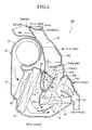
- Embodiment 2 as illustrated, in FIG. 12 , when the B/L mode is selected, the cross wall 31b of the foot door 31 protrudes to the air-mixing chamber 40 in which the cold air is mixed with the warm air. Accordingly, the cold air is prevented from flowing through the vent outlet and the def outlet disposed in the upper portion of the air-conditioning case 22 without being mixed with the warm air, thus, the air mixing effect can be obtained.
- the descriptions of other functions will be omitted because they are similar to the descriptions in Embodiment 1.
- the warm air path blocking plate 41 is integrally formed with the air-conditioning case 22, the heat pick-up phenomenon can be improved in the withdrawal position of the rotary door 31 by a simple structure which does not increase the number of parts.
- the warm air path blocking plate 42 is integrally formed to extend from the end portion of the first foot opening seal face 22c of the air conditioning case 22 with which the seal face 37a in the end portion of the circumference direction in the front side the advanced direction of the rotary door 31 has contact Accordingly, since the rotary door 31 guides the warm air to the upstream side in the advanced position, the air mixing performance can be improved, and the heat pick-up phenomenon can be improved in the withdrawal position of the rotary door 31.
- Embodiment 3 is an example in which a warm air path blocking door is provided for a higher heat pick-up improvement performance, in addition to the structure of Embodiment 1.
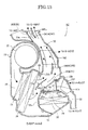
- the door shaft 31a of the foot door 31 includes concentric double shafts, One shaft 43a of the concentric double shafts is provided with a warm air path blocking door 43 for blocking the opening space of the warm air path, which is not blocked by the warm air path blocking plate 41 when the door is closed (when the vent mode is selected in the full cool mode), and for opening the opening space of the warm air path when the door is open (except when the vent mode is selected in the full cool mode).
- a warm air path blocking door 43 for blocking the opening space of the warm air path, which is not blocked by the warm air path blocking plate 41 when the door is closed (when the vent mode is selected in the full cool mode), and for opening the opening space of the warm air path when the door is open (except when the vent mode is selected in the full cool mode).
- other structures of Embodiment 2 are similar to the structures of Embodiment 1, so the same reference numbers are given to the corresponding structures to omit the descriptions.
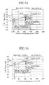
- Embodiment 3 when the vent mode is selected in the full cool mode, the heat pick-up phenomenon can be significantly remedied by using both of the warm air path blocking plate 41 and the warm air path blocking door 43.
- FIGs. 14, 15 are comparative characteristic views each illustrating a temperature difference (A-B) relative to an exit passage area of the heater core 30 when the vent mode is selected in the full cool mode by the internal air circulation.
- A denotes the average temperature of the vent outlet
- B denotes the average temperature of the evaporator exit.
- the temperature just after the evaporator 0°C
- the temperature just after the heater core 82°C
- the blast volume of the fan 10L/min
- the external air temperature about 25°C.
- the door shaft 31a of the rotary door 31 includes the concentric double shafts, and one of the concentric double shafts is provided with the warm air path blocking door 43 for blocking the opening space of the warm air path, which is not blocked by the warm air path blocking plate 41 when the door is closed, and for opening the opening space of the warm air path when the door is opened. Accordingly, when the vent mode is selected in the full cool mode, the heat pick-up phenomenon can be significantly remedied.
- the cold air from the cold air path via the evaporator is mixed with the warm air from the warm air path via the heater core in the junction region, the air in which the temperature is adjusted flows in each of the discharge path systems via the junction region, and blows out into the vehicle interior from each of the outlets communicating with each of the discharge path systems.
- the temperature adjusted air blows out if the rotary door is located in the advanced position, the mixture of the cold air from the cold air path to the junction region with the warm air from the warm air path is carried out by blocking the air flow from the junction region to the downstream side with the cross wall of the rotary door.
- the rotary door and the air mix door include the overlap layout which uses the door space inside the cross wall of the rotary door in the advanced position as the opening and closing operation space of the air mix door. Therefore, when designing the air-conditioning case, the limitation of the layout for the two doors is relaxed, and the distance between the shafts of the two doors can be reduced. As a result, the air conditioning case can be downsized while improving the air mixing performance of the cold air and the warm air.
- the rotary door is disposed as the foot door, but it can be disposed as a dedicated door.
- the withdrawal position of the rotary door can be set in another position such as a position along the cross wall of the air-conditioning case of the evaporator side.
- the cross section shape of the cross wall of the rotary door the flat plate is illustrated, but an approximately circular arc shape or another cross section shape can be used.
- the rotatable rotary door which blocks the air flow from the junction region to the downstream side by the cross wall in the advanced position, is provided in the junction region of the cold air and the warm air
- the rotary door and the air mix door include the overlap layout which uses the door space inside the cross wall of the rotary door in the advanced position as the opening and closing operation space of the air mix door, the invention is not limited to Embodiments 1-3.
Landscapes
- Physics & Mathematics (AREA)
- Thermal Sciences (AREA)
- Engineering & Computer Science (AREA)
- Mechanical Engineering (AREA)
- Air-Conditioning For Vehicles (AREA)
Abstract
Description
- The present application is based on and claims priority from Japanese Patent Application No.
2007-170353, filed on June 28. 2007 - The present invention relates to an automotive air conditioner which blows out, inside a vehicle, air in which a temperature is adjusted to a desired temperature by mixing cold air with warm air.
- There is known a conventional automotive air conditioner in which an air passageway including a cold air path via an evaporator, a warm air path via a heater core, and a plurality of discharge paths which communicates with blowing outlets (def outlet, vent outlet, foot outlet), respectively, is formed inside an air-conditioning case, and cold air and warm air distributed by an opening degree of an air mix door flow to each of the discharge paths via a junction region of the cold air and the warm air (for example, refer to
JP2001-113931A - There is also known a conventional automotive air conditioner for the purpose of reducing a space in which a door is disposed, compared with a structure which provides a rotary door, and preventing disordered air flow (for example, refer to
JP2002-307929A - There is also known a conventional automotive air conditioner for the purpose of reducing a temperature difference between a blowing temperature from a def and a temperature from a foot (for example,
JP2003-154836A - However, in the conventional techniques described in
JP2001-113931A JP2002-307929A - In the technique described in
JP2003-154836A JP2003-154836A - Moreover, since the rotary door is required to be disposed in a position which does not interfere with the movement of the air mix door, the layout of the rotary door and the air mix door is limited, for example, the distance between the shafts of two doors should be maintained at a predetermined distance or more when setting the two doors in the air-conditioning case. In addition, since the door space of the rotary door is not used as an air passageway, it is necessary to retain a necessary air passageway space in the air-conditioning case is addition to the rotary door. As a result, there is a problem in that even if there is a demand for downsizing the air-conditioning case, this demand can not be met.
- The present invention has been made in view of the above problems, and an object of the present invention is to provide an automotive air conditioner which can meet a demand for downsizing an air-conditioning case while improving an air-mixing performance of cold air and warm air.
- In order to achieve the above object, the present invention relates to an air conditioner, including: an air-
conditioning case 22 in which air passageways including acold air path 28 via anevaporator 26, awarm air path 29 via aheater core 30, and a plurality ofdischarge path systems air mix door discharge path systems 32, via a junction region J of the air and the warm air; and arotary door 31 having across wall cross wall 31b in an advanced position, therotary door 31 and theair mix door 71, including an overlap layout which uses a door space inside thecross wall 31b of therotary door 31 in the advanced position as an opening and closing operation space of theair mix door - The accompanying drawings are included to provide a further understanding of the invention, and are incorporated in and constitute a part of this specification. The drawings illustrate embodiments of the invention and, together with the specification, serve to explain the principle of the invention.
-
FIG 1 is a vertical sectional view illustrating a vent mode which blows out air from a center vent outlet and a side vent outlet in an automotive air conditioner ofEmbodiment 1. -
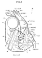
FIG. 2 is a vertical sectional view illustrating a B/L mode which blows out air from both of a vent outlet and a foot outlet in the automotive air conditioner ofEmbodiment 1. -
FIG 3 is a vertical sectional view illustrating a foot mode which blows out air from both of the side vent outlet and the foot outlet in the automotive air conditioner ofEmbodiment 1. -
FIG. 4 is a vertical sectional view illustrating a def and foot mode which blows out air from both of a def outlet and the foot outlet in the automotive air conditioner ofEmbodiment 1, -
FIG. 5 is a vertical sectional view illustrating a def mode which blows out air only from the def outlet in the automotive air conditioner ofEmbodiment 1. -
FIG. 6 is a perspective view Illustrating a foot door in the automotive air conditioner ofEmbodiment 1. -
FIG. 7 is a side view illustrating the foot door in the automotive air conditioner ofEmbodiment 1. -
FIG. 8 is a front view illustrating the foot door in the automotive air conditioner of Embodiment 1. -
FIG. 9 is a comparative characteristic view of a temperature difference (A-B) relative to an exit passage area of a heater core when the vent mode is selected in full cool mode by internal air circulation, which illustrates an experimental result for confirming a heat pickup improvement effect inEmbodiment 1. -
FIG. 10 is a comparative characteristic view of a temperature difference (A-B) relative to an exit passage area of the heater core when the vent mode is selected in full cool mode by internal air circulation, which illustrates an experimental result for confirming a heat pickup improvement effect inEmbodiment 1. -
FIG. 11 is a vertical sectional illustrating a vent mode which blows out air from a center vent outlet and a side outlet in an automotive air conditioner of Embodiment 2. -
FIG. 12 is a vertical sectional view illustrating a B/L mode which blows out air from both of a vent outlet and a foot outlet in the automotive air conditioner of Embodiment 2. -
FIG: 13 is a vertical sectional illustrating a vent mode which blows out air from a center vent outlet and a side vent outlet in an automotive air conditioner of Embodiment 3. -
FIG. 14 is a comparative characteristic view of a temperature difference (A-B) relative to an exit passage area of a heater core when a vent mode is selected in full cool mode by internal air circulation, which is an experimental result for confirming a heat pickup improvement effect in Embodiment 3. -
FIG. 15 is a comparative characteristic view of a temperature difference (A-B) relative to an exit passage area of the heater core when the vent mode is selected in full cool mode by internal air circulation, which is an experimental result for confirming a heat pickup improvement effect in Embodiment 3. - Hereinafter, embodiments of the present invention will be described with reference to the drawings.
- At first, the structure of
Embodiment 1 will be described with reference toFIGs. 1-8 . - In an
automotive air conditioner 1A according to Embodiment 1, an air passageway is formed by appropriately zoning the inside area an air-conditioning case made of a systematic resin or the like with awall 22a or the like, and the quality of the air such as the cleanness and the temperature is adjusted by air distribution members (blower 23, introduction path 24) disposed in the upstream positions of this air passageway, functional members (filter 23,evaporator 26,heater core 30, etc.) disposed in the air passageway, a cold air sideair mix door 71, and a warm air sideair mix door 72. The outlets (blowing modes) of the adjusted air can be changed by opening and closing positions of acenter vent door 341, aside vent door 342, adef door 35, and afoot door 31. - The air discharged from the
blower 23 is cleaned by passing through thefilter 25 disposed in theintroduction path 24. Moreover, theevaporator 26 constituting a part of a refrigerating cycle is disposed in the latter part (downstream side) of thefilter 25, so as to cool down the air. In this case, thefilter 25 and theevaporator 26 are disposed is the lower position of theblower 23 to be parallel to each other in the longitudinal direction, and are set in the inclination longitudinal direction such that the upper sides are shifted to the downstream side and the lower sides are shifted to the upstream side from the up and down vertical positions. By setting thefilter 25 and theevaporator 26 in this inclination longitudinal direction, the air can be easily introduced from theintroduction path 24 and a space can be formed in the lower portion of theevaporator 26. - The upper side of the
wall 22a in the downstream side of theevaporator 26 is provided with acold air path 28 in which theheater core 30 is not disposed and a cold air sideair mix door 71. The lower side of thewall 22a in the downstream side of theevaporator 26 is provided with a warm air sideair mix door 72, and the downstream position of the warm air sideair mix door 72 is provided with theheater core 30 and awarm air path 29. In this case, theheater core 30 is disposed in the horizontal direction with thewall 22a as a supporting case portion of one end side. By disposing theheater core 30 in the horizontal direction, the air from theevaporator 26 flows in the bottom face of the air-conditioning case 22, and then flows in theheater core 30 from bottom to top-Thereby, thewarm air path 29 becomes a path through which the warm air flows from bottom to top. - The air distribution ratio to the
cold air path 28 and the warm air path 49 can be changed by an opening degree of each of the cold air sideair mix door 71 disposed in the upper position of thewall 22a in the downstream of theevaporator 26 and the warm air sideair mix door 72 disposed in the lower position of thewall 22a. More particularly, inEmbodiment 1, as illustrated inFIG. 1 , when the cold air sideair mix door 71 is in the open position and the warm air sideair mix door 72 is in the closed position, the air docs not flow in thewarm air path 29, and only flows in thecold air path 28. On the other hand, as illustrated inFIG. 3 , when the cold air sideair mix door 71 is in the closed position and the warm air sideair mix door 72 is the open position, the air does not flow in thecold air path 28 and only flows in thewarm air path 29. - When the cold air side
air mix door 71 is in the midway position as illustrated inFIG. 2 , the cold air after passing through thecold air path 28 and the warm air after passing through thewarm air path 29 flow together, and the mixing of cold air and the warm air is accelerated in anair mix chamber 40 formed in a position corresponding to a junction region J. Alter the cold air and the warm air are mixed in theair mix chamber 40, the air is distributed to each ofdischarge paths discharge openings discharge paths 32. 33 and thedischarge openings center vent door 341, theside vent door 342, thedef door 35, and thefoot door 32. This outlet selection control (= mode selection control) will be described later. - In
Embodiment 1, a foot door 31 (rotary door) capable of moving between anadvanced position 31A (FIGs. 2 ,3 ,4 ) which blocks the downstream side of the junction region J and awithdrawal position 31B (FIGs. 1, 5 ) which withdraws from theadvanced position 31A is disposed in the position of the junction region J of the cold air and the warm air. Thisfoot door 31 is rotatably supported to the air-conditioning case 22, and is a rotary door which rotates about adoor shaft 31a provided in the downstream position of the upper portion of thewall 22a of the air-conditioning case 22. - As illustrated in
FIG. 6 , thefoot door 31 includes a pair of approximately fan-shaped side walls cross wall 31b which connects the outer circumference edges of theside walls door shafts 31a projecting in a direction opposite to each other from the positions to be the bases of the fan-shaped side walls 31c.Flange frames side walls cross wall 31b. Aseal member 37 is fastened to theflange frame 31d, andseal members flange frame 31f. - In the
withdrawal position 31B of thefoot door 31,surfaces seal members seal face 22c and a second foot openingseal face 22b of the air-conditioning case 22, respectively, and the performance is retained by the contact portions (FIGs. 1, 5 ). - In the
advanced position 31A of thefoot door 31, thesurface 39a of theseal member 39 has contact with the surface of a door openingseal face 22d of the air-conditioning case 22, so the sealing performance is retained by the contact portion (FIGs. 2 ,3 ,4 ). - As illustrated in
FIG 7 , in thefoot door 31. a seal face distance L2 from thedoor shaft 31a 10 thecross wall 31b in the end portion of the circumferential direction (theflange frame 31d in the end portion of the circumferential direction) in the front side (the lower side inFIG 1 ) of the advanced direction of thefoot door 31 is set to be shorter than a seal face distance L1 from thedoor shaft 31a to thecross wall 31b in the end portion of the circumferential direction (theflange frame 31 f in the end portion of the circumferential direction) in the tip side (the upper side inFIG. 1 ) of the advanced direction of thefoot door 31. More particularly, when the distance from thedoor shaft 31a ta the second foot openingseal face 22b is a seal face distance L3, the relationship L1 > L3 > L2 is established. - As illustrated in
FIG. 8 , in thefoot door 31, a seal face width W2 in the end portion of the circumferential direction in the front side of the advanced direction of thefoot door 31 is set to be shorter than a seal face width W1 in the end portion of the circumferential direction in the tip side of the advanced direction of thefoot door 31. More particularly, when the maximum width in the portion of thecross wall 31b is W3, the relationship W1> W3 > W2 is established. - As illustrated in
FIGs. 1-5 , thefoot door 31 as disposed in the junction region J of the cold air and the warm air, and blocks the air flow from the junction region J to the downstream side by thecross wall 31b in the advanced position (door open position). - As illustrated in
FIG. 2 , thefoot door 31 and the cold air sideair mix door 71 include an overlap layout which uses the door space inside thecross wall 31b of thefoot door 31 in the door open position as the opening and closing operation space of the cold air sideair mix door 71. - The
foot door 31 blocks thefoot discharge path 33 and the foot discharge opening 161 (refer toFIG. 1 ) by thecross wall 31b in the withdrawal position (closed position), and blocks the air flaw from the junction region J to the downstream side by thecross wall 31b, and uses the space inside thecross wall 31b as the cold air path or the warm air path (refer toFIG. 2 ). - The cold air side
air mix door 71 controls the opening area of thecold air path 28, which goes through theevaporator 26, by an opening degree. - As illustrated in
FIG 2 . thefoot door 31 and the cold air sideair mix door 71 are disposed such that a part of the cold air sideair mix door 71 by an opening degree on the open side overlaps with the space surrounded by thedoor shaft 31a, a pair of theside walls cross wall 31b of thefoot door 31 in the open position. More particularly, thedoor shaft 31a of thefoot door 31 and thedoor shaft 71a of the cold air sideair mix door 71 are disposed adjacent to the upper position of thewall 22a. - The downstream position of the
heater core 30 is provided with a warm airpath blocking plate 41 which blocks a part of thewarm air path 29 at least in the withdrawal position (closed position) of thefoot door 31. The warm airpath blocking plate 41 ofEmbodiment 1 is integrally formed with thefoot door 31 as illustrated inFIGs. 1-5 . More particularly, the warm airpath blocking plate 41 is provided in a position covering a part of the warm air path area in which the three directions are surrounded by a pair of theside walls cross wall 31b on the front side of the advanced direction of thefoot door 31. - Next, the functions will be described.
Hereinafter, the functions of theautomotive air conditioner 1A ofEmbodiment 1 will be described according to "air flow function in each of blowing modes", "air mixing function of cold air and warm air", "downsizing function of air-conditioning case", "increasing function of rotation angle of foot door'', and "heat pickup improvement function in full-cool", - In the vent mode (
FIG. 1 ).
In the vent mode selected state in the full cool mode as illustrated inFIG 1 . the cold air sideair mix door 71 is opened, and the warm air sideair mix door 72 is closed, Thefoot door 31 is located in the position (31B) which closes the foot outlet, thedef door 35 is located in the position (35B) which closes the def outlet. Thecenter vent door 341 rotatably supported to the air-conditioning case 22 centering on thedoor shaft 341a is located in theposition 341A which opens the center-vent outlet (C-VENT), and theside vent door 342 is located in theposition 342A which opens the side vent outlet (S-VENT). - For this reason, as illustrated in
FIG 1 , when the vent mode is selected in the full cool mode, if the cold air passing through theevaporator 26 through thecold air path 28 and thedischarge path 32, the cold air blows in the vehicle interior from the center vent outlet (C-VENT), and if the cold air after passing through the evaporator 26 passes through thecold air path 28 and the side vent discharge opening the cold air blows in the vehicle interior from the side vent outlet (S-VENT). - In the B/L mode (
FIG. 2 ).
In B/L mode selected illustrated inFIG. 2 , the cold air sideair mix door 71 is in the open side and the warm air sideair mix door 72 is in the open side. Thefoot door 31 is located in the advanced position (31A) which opens the that outlet, and thedef door 35 is located in the position (35B) which closes the def outlet. Thecenter vent door 341 rotatably supported to the air-conditionning case 22 centering on thedoor shaft 341a is located in theposition 341A which opens the center vent outlet (C-VENT), and theside vent door 342 is located in theposition 342A, which opens the side vent outlet (S-VENT). - For this reason, as illustrated in
FIG. 2 , when the B/L mode is selected, which blows out the temperature-adjusted air in which the cold air is mixed with the warm air from the vent/foot, the cold air after passing through theevaporator 26 reaches the junction region J after detouring the inner face of the warm airpath blocking plate 41 and thecross wall 31b of thefoot door 31 from thecold air path 28. The warm air after passing through theheater core 30 reaches the junction region J of the front side area of the advanced direction of thefoot door 31 from thewarm air path 29. This junction region J becomes theair mix chamber 40, and the cold air is mixed with the warm air in theair mix chamber 40, so as to be the temperature-adjusted air. - If the temperature-adjusted air of the
air mix chamber 40 passes through thedischarge path 32, the temperature-adjusted air blows into the vehicle interior from the center vent outlet (C-VENT), and a part of the temperature-adjusted air blows into the vehicle interior from the side vent outlet (S-VENT) after passing through the sidevent discharge opening 162. At the same time, the temperature-adjusted air of theair mix chamber 40 blows into the vehicle interior from the front side foot outlet (F-FOOT) after passing through thefool discharge opening 161, and blows into the vehicle interior from the rear side foot outlet (R-FOOT) after passing through thefoot discharge path 33. - In the foot mode (
FIG. 3 ).
In the foot mode selected state as illustrated inFIG 3 , cold air sideair mix door 71 is and the warm air sideair mix door 72 is opened. Thefoot door 31 is located in the advanced position (31A) which opens the foot outlet, and thedef door 35 is located in the position (35B) which closes the def outlet. Thecenter vent door 341 is located in theposition 341B which closes the center vent outlet and theside vent door 342 is located in theposition 342B which closes the side vent outlet (S-VENT) (the position which does not completely close the side vent outlet but leaves opens a part thereof), - For this reason, as illustrated in
FIG 3 , when the foot mode is selected, which blows out the warm air from the foot outlet, the warm air after passing through theheater core 30 directly or indirectly reaches the junction region J of the front area of the advanced direction, of thefoot door 31 from thewarm air path 29. The warm air from the junction region J blows into the vehicle interior from the front side foot outlet (F-FOOT) after passing through thefoot discharge opening 161, and also blows into the vehicle interior from the rear side foot outlet (R-FOOT) passing through thefoot discharge path 33. In addition, a part of warm of the junction region J blows into the vehicle interior from the side vent outlet (S-VENT). - In the def/foot mode (
FIG. 4 ).
In the def/foot mode selected state as illustrated inFIG 4 . the cold air sideair mix door 71 is closed, and the warm air sideair mix door 72 is opened. Thefoot door 31 is located in the advanced position (31A) which opens the foot outlet, and thedef door 35 rotatably supported to the air-conditioning case 22 centering on thedoor shaft 35a is located in the position (35A) which opens the def outlet. Thecenter vent door 341 is located in theposition 341B which closes the center vent outlet (C-VENT), and theside vent door 342 is located in theposition 342B which closes the side vent outlet (S-VENT) (the position which does not completely close the side vent outlet but leaves open a part thereof). - For this reason, as illustrated in
FIG. 4 , when the def/foot mode is selected, which blows out the warm air from the def/foot, the warm air after passing through theheater core 30 directly or indirectly reaches the function region J of the front side area of the advanced direction of thefoot door 31 from thewarm air path 29. The warm air from the junction region J blows into the vehicle interior from the def outlet (DEF) after passing through the space between thefoot door 31 and the air-conditioning case 22, the opening space of theside vent door 342, and thedischarge path 32. At the same time, the warm air from the junction region J blows into the vehicle interior from the front side foot outlet (F-FOOT) after passing through thefoot discharge opening 161, and blows into the vehicle interior from the rear side foot outlet (R-FOOT) after passing through thefoot discharge path 33. In addition, a part of the warm air of the junction region J blows into the vehicle interior from the side vent outlet (S-VENT). - In the def mode (
FIG. 5 ).
In the def mode selected state as illustrated inFIG. 5 , the cold air sideair mix door 71 is closed, and the warm air sideair mix door 72 is opened. Thefoot door 31 is located in the withdrawal position (31B), which closes the foot outlet, and thedef door 35 rotatably supported to the air-conditioning case 22 centering on thedoor shaft 35a is located in the position (35A) which opens the def outlet. Thecenter vent door 341 is located in theposition 341B which closes the center vent outlet (C-VENT), and theside vent door 342 is located in theposition 342B which closes the side vent outlet (S-VENT) (the position which does not completely close the side vent outlet but leaves open a part thereof). - For this reason, as illustrated in
FIG. 5 , when the def mode is selected, which blows out the warm air from the def outlet, the warm air after passing through theheater core 30 blows into the vehicle interior from the def outlet (DEF) via the inside of thefoot door 31, the opening space of theside vent door 342, and thedischarge path 32 from thewarm air path 29. In addition, a part of the warm air after passing through the opening space of theside vent door 342 blows into the vehicle interior from the side vent outlet (S-VENT). - As illustrated in
FIG. 2 , thefoot door 31 protrudes to theair mix chamber 40 in which the cold air is mixed with the warm air when the foot outlet is opened (when thefoot door 31 is located in the advanced position), so the cold air is not mixed with the warm air, and the cold air is prevented from flowing through the vent outlet and def outlet provided in the upper portion of the air-conditioning case 22. Namely, when the foot outlet is opened, theair mix chamber 40 is formed by thefoot door 31. In addition, by arranging the warm airpath blocking plate 41 in thefoot door 31, this warm airpath blocking plate 41 provides the function for guiding the cold air to the warm air side, and improves the air mixing performance. - More particularly, in the state in which the
foot door 31 is located in theadvanced position 31A as illustrated inFIG. 2 , theair mix chamber 40, which improves the mixture of the cold air from thecold air path 28 to the junction region J with the warm air from thewarm air path 29 to the junction region J, is formed by blocking the air flow from the junction region J to the downstream side with thecross wall 31b and the warm airpath blocking plate 41. - For this reason, in the
advanced position 31A of thefoot door 31, compared with thewithdrawal position 31B of thefoot door 31, the flow speed of the cold air is significantly reduced, and separation, swirl, damage and the like are caused by the significant change in the flowing direction, and also the path to the blowing outlet is extended. Accordingly, in theair mix chamber 40, the mixture of the cold air from thecold air path 28 to the junction region J with the warm air from thewarm air path 29 to the junction region J is improved, and the mixture of the cold air with the warm air is further improved by guiding the cold air to the warm air side (downward) with the warm airpath blocking plate 41. - In
Embodiment 1, thecold air path 28 and the def outlet (DEF) or the vent outlet (C-VENT, S-VENT) are disposed relatively adjacent to each other. Therefore, by setting theadvanced position 31A such that thecross wall 31b and the warm airpath blocking plate 41 are disposed between thecold air path 28 and the def outlet (DEF) or the vent outlet (C-VENT, S-VENT), the flow volume in which the cold air from thecold air path 28 directly flows into the def outlet (DEF) or the vent outlet (C-VENT, S-VENT) without mixing with the warm air from thewarm air path 29 can be effectively controlled. As a result, the increase in the temperature difference of the blowing air can be controlled between the def outlet (DEF) or the vent outlet (C-VENT, S-VENT) and the foot outlet (F-FOOT, R-FOOT). - As illustrated in
FIG. 2 , one end (thesurface 39a of the seal member 39) on the movement direction side of thecross wall 31b of thefoot door 31 is brought into contact with the door openingseal face 22d of the air-conditioning case 22, thereby, the air flowing to the downstream side from theair mix chamber 40 along the door openingseal face 22d is blocked. More particularly, the air flow is blocked to the door openingseal face 22d close to the def outlet (DEF) and the vent outlet (C-VENT, S-VENT), and the air flow is curved to thedischarge path 33 far from the def outlet (DEF) and the vent outlet (C-VENT, S-VENT). Thereby, the advantageous effects can be obtained. - The air-conditioning case is disposed in the instrument panel. However, there is a demand for ensuring the space in the vehicle interior by controlling the space occupied by the instrument panel, and a demand for disposing numerous devices inside the panel without changing the space occupied by the instrument panel. In order to respond to the above demands, it is necessary to downsize the air-conditioning case having the highest occupation rate of space. Moreover, there is a strong demand for downsizing the air-conditioning case without reducing the original air-conditioning performance.
- On the other hand, in the conventional rotary door, the door space is not used as the opening and closing operation space of the air mix door. For this reason, it is necessary to dispose the rotary door in a position which does not interfere with the operation of the air mix door, so the layout of the two doors is limited when setting the positions of the two doors in the air-conditioning case, for example, the distance between the shafts of two doors should be maintained at a predetermined distance or more. Moreover, in the conventional rotary door, the door space is not used as the air passageway. Therefore, it is necessary to retain the space of the air passageway required for ensuring the air mixing performance in the air-conditioning case, in addition to the rotary door. As a result, although there is a demand for downsizing the air-conditioning case without reducing the air-conditioning performance, this demand can not be met because of the limitation of the layout and the limitation, for ensuring the space of the air passageway.
- However, in the automotive air conditioner according to
Embodiment 1, thefoot door 31 and the cold air sideair mix door 71 include the overlap layout which uses the door space inside thecross wall 31b of thefoot door 31 in the advanced position as the opening and closing operation space of the cold air sideair mix door 71. Accordingly, when designing the air-conditioning case 22, the limitation of the layout of the twodoors door shafts foot door 31 can be used as thecold air passageway 28. As a result, without reducing the air-conditioning performance (especially the air-mixing perfarmance), the demand for downsizing the air-conditioning case 22 can be achieved. - In order to rotate the rotary door while retaining the sealing performance of the opening portion, it is necessary for the seal face distances from the door shaft to be set such that the lower side of the fan-shaped side wall of the rotary door is short and the upper side of the fan-shaped side wall of the rotary door is long. However, it is necessary to retain not only the sealing performance of the cross wall of the rotary door, but also the sealing performances of the fan-shaped side walls of the rotary door, which extend in both sides from the cross wall of the rotary door (three-direction sealing). Therefore, when the fan-shaped side walls are set such that the lower side is short and the upper side is long, the rotation angle of the rotary door is limited to an angle which does not exceed the second foot opening seal face.
- On the other hand, in the
foot door 31 according toEmbodiment 1, the sealing face distances are set to establish the relationship of L1 > L3 > L2 (refer toFIG. 7 ), and the sealing face widths are set to establish the relationship of W1 > W3 > W2 (refer toFIG. 8 ). Consequently, regarding the rotation angle of thefoot door 31 from the withdrawal position to the advanced position, it is set to obtain an angle which exceeds the second foot openingseal face 22b as illustrated inFIGs. 2-4 . - Accordingly, when the foot outlet is opened (when the
foot door 31 is located in the advanced position), thefoot door 31 can distribute, via the space formed between thefoot door 31 and the second foot openingseal face 22b, the air to the vent outlet and the def outlet which are disposed in the upper side of the space. - When the vent mode is selected in the full cool mode, the upstream side of the foot outlet is closed by the
foot door 31 in the withdrawal position, and thefoot door 31 does not protrude to thecold air path 28. Accordingly, compared with a case in which the door which closes thefoot discharge path 33 and thefoot discharge opening 161 is additionally disposed, the structure of the device can be downsized and the manufacturing costs can be controlled by reducing the number of parts. In addition, since thefoot door 31 does not protrude to thecold air path 28, the air flow resistance can be reduced when the vent mode is selected. - However, as in
Embodiment 1, when the door space of the foot door is used as the air passageway, a heat pick-up phenomenon in which the cold air flowing via thecold air path 28 from theevaporator 26 draws the warm remaining around theheater core 30 is caused when the vent mode is selected in the full cool mode. As a measure for preventing this heat pick-up phenomenon, a measure for disposing in thefoot door 31 another door which blocks the drawing of the warm air, or a measure for disposing a warm water valve which stops supplying the warm water to theheater core 30 is considered. However, if these measures are taken, the number of parts, the space and the costs are increased. - On the other hand, in
Embodiment 1, the heat pick-up phenomenon can be remedied without using another door, the warm water valve or the like when the vent mode is selected in the full cool mode. - More particularly, in
Embodiment 1, the warn airpath blocking plate 41 which closes a part, of the warm air passageway is integrally formed with thefoot door 31. Therefore, a part the warm air remaining around theheater core 30 is drawn to thecold air path 28 from the opening section of thefoot door 31, but the remaining warm air is prevented from being drawn into thecold air path 28 by the warm airpath blocking plate 41, and remains in the upper portion of the heater core 30 (refer to the dotted line arrow inFIG1 ). For this reason, when vent mode is selected in the full cool mode, the heat pick-up phenomenon which the blowing temperature can be remedied without using another door, the warm water valve, or the like. -
FIGs. 9, 10 are comparative characteristic views each illustrating a temperature difference (A-B) relative to an exit passage area of theheater core 30 when the vent mode is selected in the full cool mode by the internal air circulation. In addition, A denotes the average temperature of the vent outlet, and B denotes the average temperature of the evaporator exit. As to the experiment conditions, the temperature just after the evaporator = 0°C, the temperature just after the heater core = 82°C, the blast volume of the fan = 10L/min, and the external air temperature = about 25°C. - As illustrated in
FIG 9 , as to the experiment results in the blowing flow rate Ga = 8.0m3/min, the result (temperature difference) with the exit passage area of theheater core 30 entirely closed is Δt1 = 1.73°C, the result (temperature difference) with the exit passage area of theheater core 30 blocked by the warm airpath blocking plate 41 is Δt2 = 2.53°C, and the result (temperature difference) with the exit passage area of theheater core 30 entirely opened is Δt3 = 3.13°C. By this experiment, compared with a case in which the exit passage area of theheater core 30 is entirely opened, the improvement effects of 0.6°C (= 3.13 - 2.53) can be obtained by blocking the exit passage area of theheater core 30 with the warm airpath blocking plate 41. - As illustrated in
FIG. 10 , as to the experiment results in the blowing flow rate Ga - 3.5m3/min, the result (temperature difference) with the exit passage area of theheater core 30 entirely closed is Δt1 = 2.33°C, the results (temperature difference) with the exit passage area of theheater core 30 blocked by the warm airpath blocking plate 41 is Δt2 = 3.11 °C, and the result (temperature difference) with the exit passage area of theheater core 30 entirely opened is Δt3 = 3.61°C. By this experiment, compared with a case in which the exit passage area of theheater core 30 is entirely opened, the improvement effects of 0.5°C (= 3.61 - 3.11) can be obtained by blocking the exit passage area of thehater core 30 with the warm airpath blocking plate 41. - Next the effects will be described.
In theautomotive air conditioner 1A according toEmbodiment 1, the following effects can be obtained. - (1) The automotive air conditioner includes the air-
conditioning case 22 in which the air passageways having thecold air path 28 via theevaporator 26, thewarm air path 29 via theheater core 30, and a plurality ofdischarge path systems air mix door discharge path systems rotary door 31 having thecross wall 31b, which is rotatably disposed in the junction region J of the cold air and the warm air and blocks the air flow from the junction region J to the downstream side by thecross wall 31b in the advanced position. Therotary door 31 and theair mix door 71. 72 include the overlap layout which uses the door space inside thecross wall 31b of therotary door 31 in the advanced position as the opening and closing operation space of theair mix door conditioning case 22 can be met while achieving the improvement in the air mixing performance of the cold air and the warm air. - (2) The
rotary door 31 is the foot door which blocks the footdischarge path system cross wall 31b in the withdrawal position, blocks the air flow from the junction region J to the downstream side by thecross wall 31b in the advanced position, and uses the door space as the path of the cold air and the path of the warm air. The air mix door is the cold air sideair mix door 71 which controls the opening area of thecold air path 28 via theevaporator 26, and thefoot door 31 and the cold air sideair mix door 71 are disposed such that a part of the cold air sideair mix door 71 by the opening degree on the open side overlaps with the door space surrounded by thedoor shaft 31a, a pair ofside walls cross wall 31b of thefoot door 31 in the advanced position. Accordingly, since the rotary door has the function as the foot door, the number of the parts can be reduced without disposing the foot door in addition to the rotary door, and the air-conditioning case 22 can be further downsized. - (3) In the
rotary door 31, the seal face distance L2 from thedoor shaft 31a to the end portion of the circumference direction in the front side of the advanced direction is shorter than the seal face distance L1 from thedoor shaft 31a to the end portion of the circumference direction in the tip side of the advanced direction, and the seal face width W2 in the end portion of the circumference direction in the front side of the advanced direction is shorter than the seal face width W1 in the end portion of the circumference direction in the tip side of the advanced direction. Accordingly, the rotation angle of therotary door 31 can be increased, thus, the air passageways to the vent outlet and the def outlet in the advanced position of the rotary door can be appropriately retained to a high setting degree. - (4) The downstream position of the
heater core 30 is provided with the warm airpath blocking plate 41 which blocks a part of thewarm air path 29 in a state in which at least therotary door 31 is located in the withdrawal position. Accordingly, in the withdrawal position of therotary door 31, the heat pick-up phenomenon can be remedied without providing another door, the warm water valve or the like. - (5) Since the warm air
path blocking plate 41 is integrally formed with therotary door 31, the heat pick-up phenomenon can be improved in the withdrawal position of therotary door 31 by a simple structure which does not increase the number of parts. - (6) The
rotary door 31 includes a pair ofside walls 3c, 31c parallel to each other each having an approximately fan shape, thecross wall 31b which connects the outer circumference edges of theside walls door shaft 31a which is located in the position which is the base of the fan shape of theside wall 31c, and therotary door 31 rotates centering on thedoor shaft 31a rotatably supported to the air-conditioning case 22. The warm airpath blocking plate 41 is set in the position for covering a part of the region of the warm air path in which the three directions are surrounded by theside walls cross wall 31b of the front side of the advanced direction of therotary door 31. Accordingly, since therotary door 31 in the advanced position guides the cold air to the warm air side, the air mixing performance can be improved, and the heat pick-up can be improved in the withdrawal position of therotary door 31. - Embodiment 2 is an example in which a warm air path blocking plate for blocking a part of the warm air passageway in a state in which at least the
foot door 31 is in the withdrawal position is integrally formed with the air-conditioning case - At first, the structure will be described with reference to
FIGs. 11 ,12 . - A warm air
path blocking plate 42 in anautomotive air conditioner 1B according to Embodiment 2 is integrally formed with an air-conditioning case 22 as illustrated inFIGs. 11 ,12 , relative to the warm airpath blocking plate 41 according toEmbodiment 1 integrally formed with thefoot door 31. More particularly, the warmair blocking plate 42 is integrally formed to extend from the end portion of a first foot openingseal face 22c of the air-conditioning case 22 with which asealing face 37a in the end portion of the circumference direction in the front side of the advanced direction of thefoot door 31 has contact. In addition, other structures are the same as the structures ofEmbodiment 1, therefore, the same reference numbers are applied to the corresponding structures for omitting the descriptions. - Next, the function will be described.
In Embodiment 2, similar toEmbodiment 1, the heat pick-up phenomenon can be remedied without using another door, the warm water valve, or the like when the vent mode is selected in the full cool mode. Namely, in Embodiment 2, the warm airpath blocking plate 42 which closes a part of the warm air path is integrally formed with the air-conditioning case 22. Therefore, as illustrated by the dotted arrow in.FIG 11 , a part of the warm air renaming around theheater core 30 is drawn to thecold air path 28 from the opening portion of thefoot door 31, the drawing of the remaining warm air to thecold air path 28 is blocked by the warm airpath blocking plate 42, and the remaining warm air remains in the upper portion of theheater core 30. - In Embodiment 2, as illustrated, in
FIG. 12 , when the B/L mode is selected, thecross wall 31b of thefoot door 31 protrudes to the air-mixingchamber 40 in which the cold air is mixed with the warm air. Accordingly, the cold air is prevented from flowing through the vent outlet and the def outlet disposed in the upper portion of the air-conditioning case 22 without being mixed with the warm air, thus, the air mixing effect can be obtained. In addition, by adding the warm airpath blocking plate 42 to the air-conditioning case 22, the warm airpath blocking plate 42 guides the warm air to the upstream side of the junction region J (= air mixing chamber 40), so as to improve the air-mixing performance. In addition, the descriptions of other functions will be omitted because they are similar to the descriptions inEmbodiment 1. - Next, the effects will be described.
In the automotive air-conditioner 1B according to Embodiment 2, the following effects can be obtained in addition to the effects of (1) to (4) inEmbodiment 1. - (7) Since the warm air
path blocking plate 41 is integrally formed with the air-conditioning case 22, the heat pick-up phenomenon can be improved in the withdrawal position of therotary door 31 by a simple structure which does not increase the number of parts. - (8) The warm air
path blocking plate 42 is integrally formed to extend from the end portion of the first foot openingseal face 22c of theair conditioning case 22 with which theseal face 37a in the end portion of the circumference direction in the front side the advanced direction of therotary door 31 has contact Accordingly, since therotary door 31 guides the warm air to the upstream side in the advanced position, the air mixing performance can be improved, and the heat pick-up phenomenon can be improved in the withdrawal position of therotary door 31. - Embodiment 3 is an example in which a warm air path blocking door is provided for a higher heat pick-up improvement performance, in addition to the structure of
Embodiment 1. - At first, the structure will be described with reference to
FIG. 13 . - In an
automotive air conditioner 1C according to Embodiment 3, thedoor shaft 31a of thefoot door 31 includes concentric double shafts, Oneshaft 43a of the concentric double shafts is provided with a warm airpath blocking door 43 for blocking the opening space of the warm air path, which is not blocked by the warm airpath blocking plate 41 when the door is closed (when the vent mode is selected in the full cool mode), and for opening the opening space of the warm air path when the door is open (except when the vent mode is selected in the full cool mode). In addition, other structures of Embodiment 2 are similar to the structures ofEmbodiment 1, so the same reference numbers are given to the corresponding structures to omit the descriptions. - Next, the function will be described.
In Embodiment 3, when the vent mode is selected in the full cool mode, the heat pick-up phenomenon can be significantly remedied by using both of the warm airpath blocking plate 41 and the warm airpath blocking door 43. -
FIGs. 14, 15 are comparative characteristic views each illustrating a temperature difference (A-B) relative to an exit passage area of theheater core 30 when the vent mode is selected in the full cool mode by the internal air circulation. In addition, A denotes the average temperature of the vent outlet and B denotes the average temperature of the evaporator exit. As to the experiment conditions, the temperature just after the evaporator = 0°C, the temperature just after the heater core = 82°C, the blast volume of the fan = 10L/min, and the external air temperature = about 25°C. - As illustrated in
FIG 14 , as to the experiment results in the blowing flow rate Ga = 8,0m3/min, the result (temperature difference) with the exit passage area of theheater core 30 blocked with the warm airpath blocking plate 41 and the warm airpath blocking door 43 is Δt1' = 1.85°C, the result (temperature difference) with the exit passage area of theheater core 30 blocked only by the warm airpath blocking plate 41 is Δt2 = 2.53°C, and the result (temperature difference) with the exit passage area of theheater core 30 entirely opened is Δt3 = 3.13°C. By this experiment, compared with a case in which the exit passage area of theheater core 30 is blocked only by the warm airpath blocking plate 41, the improved effects of 0.68°C (= 2.53 - 1.85) can be obtained by blocking the exit passage area of theheater core 30 with the warm airpath blocking plate 41 and the warm airpath blocking door 43. In addition, compared with a case in which the exit passage area of theheater core 30 is entirely opened, the improved effects of 1.28°C (= 0.6 + 0.68) can be obtained. - As illustrated in
FIG. 15 , as to the experiment results in the blowing flow rate Ga =3.5m3/min, the result with the exit passage area of theheater core 30 blocked with the warm airpath blocking plate 41 and the warm airpath blocking door 43 is Δt1 = 2.5°C, the result (temperature difference) with the exit passage area of theheater core 30 blocked only with the warm airpath blocking plate 41 is Δt2 = 3.11°C, and the result (temperature difference) with the exit passage area of theheater core 30 entirely opened is Δt3 = 3.61 °C. By this experiment, compared with a case in which the exit passage area of theheater core 30 is blocked only by the warm airpath blocking plate 41, the improved effects of 0.61°C (=3.11-2.5) can be obtained by blocking the exit passage area of theheater core 30 with the warm airpath blocking plate 41 and the warm airpath blocking plate 41. In addition, the improved effects of 1.11°C (= 0-5 + 0.61) can be obtained, compared with a case in which the exit passage area of theheater core 30 is entirely opened. - Next, the effects will be described.
In theautomotive air conditioner 1C according to Embodiment 3, the following effects can be obtained in addition to the effects (1) to (6) ofEmbodiment 1. - (9) The
door shaft 31a of therotary door 31 includes the concentric double shafts, and one of the concentric double shafts is provided with the warm airpath blocking door 43 for blocking the opening space of the warm air path, which is not blocked by the warm airpath blocking plate 41 when the door is closed, and for opening the opening space of the warm air path when the door is opened. Accordingly, when the vent mode is selected in the full cool mode, the heat pick-up phenomenon can be significantly remedied. - As described above, in the automotive air conditioner according to one embodiment of the present invention, in the air passageways of the air-conditioning case, the cold air from the cold air path via the evaporator is mixed with the warm air from the warm air path via the heater core in the junction region, the air in which the temperature is adjusted flows in each of the discharge path systems via the junction region, and blows out into the vehicle interior from each of the outlets communicating with each of the discharge path systems. When the temperature adjusted air blows out, if the rotary door is located in the advanced position, the mixture of the cold air from the cold air path to the junction region with the warm air from the warm air path is carried out by blocking the air flow from the junction region to the downstream side with the cross wall of the rotary door. In addition, the rotary door and the air mix door include the overlap layout which uses the door space inside the cross wall of the rotary door in the advanced position as the opening and closing operation space of the air mix door. Therefore, when designing the air-conditioning case, the limitation of the layout for the two doors is relaxed, and the distance between the shafts of the two doors can be reduced. As a result, the air conditioning case can be downsized while improving the air mixing performance of the cold air and the warm air.
- As described above, although the present invention has been described in terms of Embodiments 1-3, it is not limited thereto. It should be appreciated that variations may be made in the embodiments described by persons skilled in the art without departing from the scope of the present invention as defined by the following claims.
- For example, the rotary door is disposed as the foot door, but it can be disposed as a dedicated door. When the rotary door is disposed as the dedicated door, the withdrawal position of the rotary door can be set in another position such as a position along the cross wall of the air-conditioning case of the evaporator side. In addition, as the cross section shape of the cross wall of the rotary door, the flat plate is illustrated, but an approximately circular arc shape or another cross section shape can be used.
- Namely, as long as the rotatable rotary door, which blocks the air flow from the junction region to the downstream side by the cross wall in the advanced position, is provided in the junction region of the cold air and the warm air, and the rotary door and the air mix door include the overlap layout which uses the door space inside the cross wall of the rotary door in the advanced position as the opening and closing operation space of the air mix door, the invention is not limited to Embodiments 1-3.
Claims (9)
- An automotive air conditioner, comprising:an air-conditioning case (22) in which air passageways including a cold air path (28) via an evaporator (26), a warm air path (29) via a heater core (30), and a plurality of discharge path systems (32, 33) communicating with outlets, respectively, are formed;an air mix door (71, 72) which distributes cold air and warm air by an opening degree to each of the discharge path systems (32, 33) via a junction region (J) of the cold air and the warm air; anda rotary door (31) having a cross wall (31b), which is rotatably disposed in the junction region (J) of the cold air and the warm air and blocks air flow from the junction region (J) to a downstream side by the cross wall (31b) in an advanced position,the rotary door (31) and the air mix door (71, 72) including an overlap layout which uses a door space inside the cross wall (31b) of the rotary door (31) in the advanced position as an opening and closing operation space of the air mix door (71, 72).
- The automotive air conditioner according to Claim 1, wherein
the rotary door (31) is a foot door which blocks a foot discharge path system (33, 161) by the cross wall (31b) in a withdrawal position, blocks the air flow from the junction region (J) to the downstream side by the cross wall (31b) in the advanced position, and uses the door space as a path of the cold air and a path of the warm air,
the air mix door is a cold air side air mix door (71) which controls an opening area of the cold air path (28) via the evaporator (26), and
the foot door (31) and the cold air side air mix door (71) are disposed such that a part of the cold air side air mix door (71) by an opening degree on an open side overlaps with the door space surrounded by a door shaft (31a), a pair of side walls (31c, 31c) and the cross wall (31b) of the foot door (31) in the advanced position. - The automotive air conditioner according to Claim 1 or Claim 2, wherein
in the rotary door (31), a seal face distance (L2) from a door shaft (31a) to an end portion of a circumference direction in a front side of the advanced direction is shorter than a seal face distance (L1) from the door shaft (31a) to an end portion of a circumference direction in a tip side of the advanced direction, and a seal face width (W2) in the end portion of the circumference direction in the front side of the advanced direction is shorter than a seal face width (W3) in the end portion of the circumference direction in the tip side of the advanced direction. - The automotive air conditioner according to any one of Claims 1 to 3, wherein
the downstream position of the heater core (30) is provided with a warm air path blocking plate (41) which blocks a part of the warm air path in a state in which at least the rotary door (31) is located in a withdrawal position. - The automotive air conditioner according to Claim 4, wherein
the warm air path blocking plate (41) is integrally formed with the rotary door (31). - The automotive air conditioner according to Claim 5, wherein
the rotary door (31) includes a pair of side walls (31c, 31c) parallel to each other each having an approximately fan shape, the cross wall (31b) which connects outer circumference edges of the side walls, and a door shaft (31a) which is located in a position which is a base of the fan shape of the side wall, and the rotary door (31) rotates centering on the door shaft (31a) rotatably supported to the air-conditioning case (22), and
the warm air path blocking plate (41) is set in a position for covering a part of a region of the warm air path in which three directions are surrounded by the side walls (31c, 31c) and the cross wall (31b) of the front side of the advanced direction of the rotary door (31). - The automotive air conditioner according to Claim 4, wherein
the warm air path blocking plate (42) is integrally formed with the air-conditioning case (22). - The automotive air conditioner according to Claim 7, wherein
the warm air path blocking plate (42) is integrally formed to extend from an end portion of a first foot opening seal face (22c) of the air conditioning case (22) with which a seal face (37a) in an end portion of a circumference direction in a front side the advanced direction of the rotary door (31) has contact. - The automotive air conditioner according to Claim 6, wherein
the door shaft (31a) of the rotary door (31) includes concentric double shafts, and
one of the concentric double shafts is provided with a warm air path blocking door (43) for blocking an opening space of the warm air path, which is not blocked by the warm air path blocking plate (41) when the door is closed, and for opening the opening space of the warm air path when the door is opened.
Applications Claiming Priority (1)
| Application Number | Priority Date | Filing Date | Title |
|---|---|---|---|
| JP2007170353A JP4464427B2 (en) | 2007-06-28 | 2007-06-28 | Automotive air conditioner |
Publications (2)
| Publication Number | Publication Date |
|---|---|
| EP2008841A1 true EP2008841A1 (en) | 2008-12-31 |
| EP2008841B1 EP2008841B1 (en) | 2009-12-30 |
Family
ID=39739532
Family Applications (1)
| Application Number | Title | Priority Date | Filing Date |
|---|---|---|---|
| EP08159123A Revoked EP2008841B1 (en) | 2007-06-28 | 2008-06-26 | Automotive air conditioner |
Country Status (5)
| Country | Link |
|---|---|
| US (1) | US8403735B2 (en) |
| EP (1) | EP2008841B1 (en) |
| JP (1) | JP4464427B2 (en) |
| CN (1) | CN101332753B (en) |
| DE (1) | DE602008000472D1 (en) |
Cited By (1)
| Publication number | Priority date | Publication date | Assignee | Title |
|---|---|---|---|---|
| CN115352252A (en) * | 2022-09-14 | 2022-11-18 | 重庆长安汽车股份有限公司 | Hidden air outlet and car |
Families Citing this family (22)
| Publication number | Priority date | Publication date | Assignee | Title |
|---|---|---|---|---|
| KR100935074B1 (en) * | 2008-04-17 | 2009-12-31 | 모딘코리아 유한회사 | Car air conditioner |
| FR2942996B1 (en) * | 2009-03-10 | 2011-06-03 | Valeo Systemes Thermiques | HEATING, VENTILATION AND / OR AIR CONDITIONING INSTALLATION WITH MODIFIED AIR CHANNEL ACCORDING TO VERSION. |
| US8721408B2 (en) * | 2009-11-18 | 2014-05-13 | Keihin Corporation | Air conditioner for vehicle |
| DE102010062326A1 (en) * | 2010-12-02 | 2012-06-06 | Behr Gmbh & Co. Kg | Automotive air conditioning system |
| JP5477329B2 (en) * | 2011-04-19 | 2014-04-23 | 株式会社デンソー | Air conditioner for vehicles |
| FR2984806B1 (en) * | 2011-12-23 | 2015-10-16 | Valeo Systemes Thermiques | HOUSING OF A HEATING UNIT, VENTILATION AND / OR AIR CONDITIONING AND SHUTTER FOR SUCH A CAISSON |
| JP6101065B2 (en) * | 2012-12-07 | 2017-03-22 | 株式会社日本クライメイトシステムズ | Air conditioner for vehicles |
| JP6115462B2 (en) * | 2013-12-17 | 2017-04-19 | 株式会社デンソー | Air conditioning unit |
| JP6371533B2 (en) * | 2014-02-03 | 2018-08-08 | 株式会社日本クライメイトシステムズ | Air conditioner for vehicles |
| DE102014105035B4 (en) | 2014-04-09 | 2020-03-05 | Hanon Systems | Motor vehicle air conditioning system with several control flaps |
| JP6287777B2 (en) * | 2014-11-21 | 2018-03-07 | 株式会社デンソー | Air conditioner for vehicles |
| DE102015109354A1 (en) | 2015-06-12 | 2016-12-15 | Halla Visteon Climate Control Corporation | Arrangement for air distribution for an air conditioning system of a motor vehicle |
| CN104999889B (en) * | 2015-06-25 | 2017-04-05 | 中国第一汽车股份有限公司 | For the HVAC assemblies of automotive air-conditioning system |
| CN108290472B (en) * | 2015-11-27 | 2021-06-22 | 翰昂汽车零部件有限公司 | Refrigerating and heating module |
| US10479161B2 (en) * | 2016-01-18 | 2019-11-19 | Hanon Systems | Vehicle air-conditioning system |
| JP7000358B2 (en) * | 2017-02-10 | 2022-02-04 | 日本碍子株式会社 | Cold / warm air generation system |
| JP6404994B1 (en) * | 2017-05-30 | 2018-10-17 | 三菱重工サーマルシステムズ株式会社 | Air conditioner for vehicles |
| WO2020003500A1 (en) * | 2018-06-29 | 2020-01-02 | 三菱重工サーマルシステムズ株式会社 | Vehicle air conditioning apparatus |
| US11292319B2 (en) * | 2019-03-28 | 2022-04-05 | GM Global Technology Operations LLC | Operation of a HVAC system to desorb a filter |
| KR20210021796A (en) * | 2019-08-19 | 2021-03-02 | 현대자동차주식회사 | Vehicle hvac system |
| WO2021127314A1 (en) * | 2019-12-20 | 2021-06-24 | Gentherm Incorporated | Air distribution device for a vehicle seat |
| CN120769831A (en) | 2023-01-27 | 2025-10-10 | 胜牌全球产品知识产权有限公司 | Reusable or refillable containers for dispensing motor oil |
Citations (7)
| Publication number | Priority date | Publication date | Assignee | Title |
|---|---|---|---|---|
| JP2001113931A (en) | 1999-10-15 | 2001-04-24 | Calsonic Kansei Corp | Air conditioner for integrated vehicle |
| US20010012756A1 (en) * | 1999-12-07 | 2001-08-09 | Michael Komowski | Air flap for a ventilation, heating or air conditioning system of a motor vehicle |
| EP1219477A2 (en) * | 2000-12-28 | 2002-07-03 | Calsonic Kansei Corporation | Automotive air conditioner |
| JP2002307929A (en) | 2001-04-17 | 2002-10-23 | Denso Corp | Vehicle air conditioner |
| JP2003154836A (en) | 2001-11-22 | 2003-05-27 | Denso Corp | Vehicle air conditioner |
| DE10161997A1 (en) * | 2001-12-18 | 2003-06-05 | Daimler Chrysler Ag | Air conditioning or heating unit has cold air control unit arranged so that as it moves to reduce aperture, its coverage of air inlet surface of heat exchanger is reduced |
| US20080108293A1 (en) * | 2006-11-07 | 2008-05-08 | Haupt Eric K | Temperature door for a vehicle and heating, ventilation, and air conditioning system |
Family Cites Families (24)
| Publication number | Priority date | Publication date | Assignee | Title |
|---|---|---|---|---|
| US5062352A (en) * | 1990-07-16 | 1991-11-05 | General Motors Corporation | Motor vehicle heating, ventilating and air conditioning system with combined mode/temperature door |
| JP3735901B2 (en) * | 1995-02-03 | 2006-01-18 | 株式会社デンソー | Air passage switching device and vehicle air conditioner using the same |
| JP4002681B2 (en) * | 1998-08-10 | 2007-11-07 | カルソニックカンセイ株式会社 | Air conditioner for automobile |
| FR2787393B1 (en) * | 1998-12-22 | 2001-03-30 | Valeo Climatisation | AUTOMOTIVE VEHICLE HEATING AND / OR AIR CONDITIONING DEVICE WITH IMPROVED AIR MIXING |
| JP4253960B2 (en) * | 1999-11-18 | 2009-04-15 | 株式会社デンソー | Air conditioner for vehicles |
| ES2238959T3 (en) * | 1999-12-21 | 2005-09-16 | BEHR GMBH & CO. KG | INSTALLATION OF HEATING OR AIR CONDITIONING FOR A MOTOR VEHICLE. |
| DE10031991B4 (en) * | 2000-06-30 | 2004-02-05 | Valeo Klimasysteme Gmbh | damper |
| FR2814986B1 (en) * | 2000-10-11 | 2003-02-07 | Valeo Climatisation | AIR CONDITIONING INSTALLATION OF A VEHICLE WITH TWO ZONES OF MIXING |
| JP2002274148A (en) * | 2001-03-16 | 2002-09-25 | Denso Corp | Vehicle air conditioner |
| KR100429482B1 (en) | 2001-04-03 | 2004-05-03 | 가부시키가이샤 덴소 | Vehicle air conditioner |
| JP3894028B2 (en) * | 2002-04-11 | 2007-03-14 | 株式会社デンソー | Air conditioner for vehicles |
| JP4089390B2 (en) * | 2002-11-05 | 2008-05-28 | 株式会社デンソー | Air conditioner for vehicles |
| JP3931818B2 (en) * | 2003-02-13 | 2007-06-20 | 株式会社デンソー | Air conditioner for vehicles |
| US6881140B2 (en) * | 2003-03-31 | 2005-04-19 | Trw Automotive U.S. Llc | Apparatus for mixing air in a vehicle HVAC system |
| JP2005138707A (en) * | 2003-11-06 | 2005-06-02 | Denso Corp | Air conditioner for vehicles |
| DE10352533A1 (en) * | 2003-11-07 | 2005-06-02 | Behr Gmbh & Co. Kg | drum flap |
| JP2005145190A (en) * | 2003-11-13 | 2005-06-09 | Denso Corp | Air conditioner for vehicles |
| FR2862911B1 (en) * | 2003-11-28 | 2006-03-03 | Valeo Climatisation | DEVICE FOR HEATING-VENTILATION AND / OR AIR CONDITIONING OF A VEHICLE HABITACLE WITH ZONE TEMPERATURE ADJUSTMENT |
| DE102004027689A1 (en) * | 2004-06-07 | 2006-01-05 | Denso Automotive Deutschland Gmbh | Air conditioning for a motor vehicle |
| JP4274089B2 (en) * | 2004-09-15 | 2009-06-03 | 株式会社デンソー | Air conditioner for vehicles |
| FR2878469B1 (en) | 2004-11-29 | 2009-09-25 | Valeo Climatisation Sa | DEVICE FOR DISTRIBUTING AIR FLOWS, IN PARTICULAR FOR AN APPARATUS FOR HEATING, VENTILATION AND / OR AIR CONDITIONING OF A MOTOR VEHICLE HABITACLE |
| JP4425842B2 (en) * | 2005-09-20 | 2010-03-03 | 株式会社ケーヒン | Air conditioner for vehicles |
| JP4569439B2 (en) * | 2005-10-07 | 2010-10-27 | 株式会社デンソー | Air conditioner for vehicles |
| JP5107622B2 (en) * | 2006-08-22 | 2012-12-26 | カルソニックカンセイ株式会社 | Automotive air conditioner |
-
2007
- 2007-06-28 JP JP2007170353A patent/JP4464427B2/en not_active Expired - Fee Related
-
2008
- 2008-06-26 DE DE602008000472T patent/DE602008000472D1/en not_active Expired - Fee Related
- 2008-06-26 US US12/213,948 patent/US8403735B2/en not_active Expired - Fee Related
- 2008-06-26 EP EP08159123A patent/EP2008841B1/en not_active Revoked
- 2008-06-27 CN CN2008101261446A patent/CN101332753B/en not_active Expired - Fee Related
Patent Citations (7)
| Publication number | Priority date | Publication date | Assignee | Title |
|---|---|---|---|---|
| JP2001113931A (en) | 1999-10-15 | 2001-04-24 | Calsonic Kansei Corp | Air conditioner for integrated vehicle |
| US20010012756A1 (en) * | 1999-12-07 | 2001-08-09 | Michael Komowski | Air flap for a ventilation, heating or air conditioning system of a motor vehicle |
| EP1219477A2 (en) * | 2000-12-28 | 2002-07-03 | Calsonic Kansei Corporation | Automotive air conditioner |
| JP2002307929A (en) | 2001-04-17 | 2002-10-23 | Denso Corp | Vehicle air conditioner |
| JP2003154836A (en) | 2001-11-22 | 2003-05-27 | Denso Corp | Vehicle air conditioner |
| DE10161997A1 (en) * | 2001-12-18 | 2003-06-05 | Daimler Chrysler Ag | Air conditioning or heating unit has cold air control unit arranged so that as it moves to reduce aperture, its coverage of air inlet surface of heat exchanger is reduced |
| US20080108293A1 (en) * | 2006-11-07 | 2008-05-08 | Haupt Eric K | Temperature door for a vehicle and heating, ventilation, and air conditioning system |
Cited By (2)
| Publication number | Priority date | Publication date | Assignee | Title |
|---|---|---|---|---|
| CN115352252A (en) * | 2022-09-14 | 2022-11-18 | 重庆长安汽车股份有限公司 | Hidden air outlet and car |
| CN115352252B (en) * | 2022-09-14 | 2024-05-28 | 重庆长安汽车股份有限公司 | Hidden air outlet and car |
Also Published As
| Publication number | Publication date |
|---|---|
| US20090068939A1 (en) | 2009-03-12 |
| CN101332753B (en) | 2010-11-10 |
| JP2009006857A (en) | 2009-01-15 |
| CN101332753A (en) | 2008-12-31 |
| DE602008000472D1 (en) | 2010-02-11 |
| US8403735B2 (en) | 2013-03-26 |
| JP4464427B2 (en) | 2010-05-19 |
| EP2008841B1 (en) | 2009-12-30 |
Similar Documents
| Publication | Publication Date | Title |
|---|---|---|
| EP2008841B1 (en) | Automotive air conditioner | |
| US6821088B2 (en) | Centrifugal blower having noise-reduction structure | |
| US10953720B2 (en) | Air conditioner for vehicle | |
| JP4173646B2 (en) | Air conditioner for vehicles | |
| EP1787836B1 (en) | Vehicular air conditioner | |
| EP3524452A1 (en) | Air conditioning unit for vehicle | |
| KR102182344B1 (en) | Air conditioner for vehicle | |
| US20080223546A1 (en) | Air Conditioner for Vehicles Having Two Layer Air Flow Installed Therein | |
| US9724977B2 (en) | Rear air conditioner for vehicle | |
| CN100447005C (en) | Vehicle air conditioner | |
| CN113748033A (en) | Air conditioner for vehicle | |
| US11787264B2 (en) | Air conditioner for vehicle | |
| KR101709981B1 (en) | Air conditioning system for automotive vehicles | |
| KR20160135033A (en) | Air conditioner for vehicle | |
| JP4120393B2 (en) | Air conditioner for vehicles | |
| KR102748521B1 (en) | Rear air conditioner for vehicle | |
| US20230347711A1 (en) | Air conditioner for vehicle | |
| KR20170040818A (en) | Air conditioner for vehicle | |
| JP2003039929A (en) | Air conditioner | |
| KR102533416B1 (en) | Air conditioner for vehicle | |
| KR102559253B1 (en) | Air conditioner for vehicle | |
| KR102830899B1 (en) | Air conditioner for vehicle | |
| KR102947774B1 (en) | Air conditioning system for automotive vehicles | |
| KR102731451B1 (en) | Blower unit of air conditioner for vehicle | |
| JP2004082845A (en) | Air-conditioning air distribution system for vehicles |
Legal Events
| Date | Code | Title | Description |
|---|---|---|---|
| PUAI | Public reference made under article 153(3) epc to a published international application that has entered the european phase |
Free format text: ORIGINAL CODE: 0009012 |
|
| 17P | Request for examination filed |
Effective date: 20080626 |
|
| AK | Designated contracting states |
Kind code of ref document: A1 Designated state(s): AT BE BG CH CY CZ DE DK EE ES FI FR GB GR HR HU IE IS IT LI LT LU LV MC MT NL NO PL PT RO SE SI SK TR |
|
| AX | Request for extension of the european patent |
Extension state: AL BA MK RS |
|
| GRAP | Despatch of communication of intention to grant a patent |
Free format text: ORIGINAL CODE: EPIDOSNIGR1 |
|
| AKX | Designation fees paid |
Designated state(s): DE FR GB |
|
| GRAS | Grant fee paid |
Free format text: ORIGINAL CODE: EPIDOSNIGR3 |
|
| GRAA | (expected) grant |
Free format text: ORIGINAL CODE: 0009210 |
|
| AK | Designated contracting states |
Kind code of ref document: B1 Designated state(s): DE FR GB |
|
| REG | Reference to a national code |
Ref country code: GB Ref legal event code: FG4D |
|
| REF | Corresponds to: |
Ref document number: 602008000472 Country of ref document: DE Date of ref document: 20100211 Kind code of ref document: P |
|
| PLBI | Opposition filed |
Free format text: ORIGINAL CODE: 0009260 |
|
| PLAX | Notice of opposition and request to file observation + time limit sent |
Free format text: ORIGINAL CODE: EPIDOSNOBS2 |
|
| 26 | Opposition filed |
Opponent name: VALEO SYSTEMES THERMIQUES Effective date: 20100930 |
|
| PLAF | Information modified related to communication of a notice of opposition and request to file observations + time limit |
Free format text: ORIGINAL CODE: EPIDOSCOBS2 |
|
| PG25 | Lapsed in a contracting state [announced via postgrant information from national office to epo] |
Ref country code: DE Free format text: LAPSE BECAUSE OF NON-PAYMENT OF DUE FEES Effective date: 20110101 |
|
| PLBB | Reply of patent proprietor to notice(s) of opposition received |
Free format text: ORIGINAL CODE: EPIDOSNOBS3 |
|
| APBM | Appeal reference recorded |
Free format text: ORIGINAL CODE: EPIDOSNREFNO |
|
| APBP | Date of receipt of notice of appeal recorded |
Free format text: ORIGINAL CODE: EPIDOSNNOA2O |
|
| APAH | Appeal reference modified |
Free format text: ORIGINAL CODE: EPIDOSCREFNO |
|
| APBQ | Date of receipt of statement of grounds of appeal recorded |
Free format text: ORIGINAL CODE: EPIDOSNNOA3O |
|
| REG | Reference to a national code |
Ref country code: FR Ref legal event code: PLFP Year of fee payment: 8 |
|
| PGFP | Annual fee paid to national office [announced via postgrant information from national office to epo] |
Ref country code: GB Payment date: 20150624 Year of fee payment: 8 |
|
| PGFP | Annual fee paid to national office [announced via postgrant information from national office to epo] |
Ref country code: FR Payment date: 20150608 Year of fee payment: 8 |
|
| APBU | Appeal procedure closed |
Free format text: ORIGINAL CODE: EPIDOSNNOA9O |
|
| REG | Reference to a national code |
Ref country code: DE Ref legal event code: R064 Ref document number: 602008000472 Country of ref document: DE Ref country code: DE Ref legal event code: R103 Ref document number: 602008000472 Country of ref document: DE |
|
| RDAF | Communication despatched that patent is revoked |
Free format text: ORIGINAL CODE: EPIDOSNREV1 |
|
| RDAG | Patent revoked |
Free format text: ORIGINAL CODE: 0009271 |
|
| STAA | Information on the status of an ep patent application or granted ep patent |
Free format text: STATUS: PATENT REVOKED |
|
| 27W | Patent revoked |
Effective date: 20160316 |
|
| GBPR | Gb: patent revoked under art. 102 of the ep convention designating the uk as contracting state |
Effective date: 20160316 |