EP2008807A2 - Ceramic matrix composite structure having fluted core and method of making the same - Google Patents
Ceramic matrix composite structure having fluted core and method of making the same Download PDFInfo
- Publication number
- EP2008807A2 EP2008807A2 EP08158706A EP08158706A EP2008807A2 EP 2008807 A2 EP2008807 A2 EP 2008807A2 EP 08158706 A EP08158706 A EP 08158706A EP 08158706 A EP08158706 A EP 08158706A EP 2008807 A2 EP2008807 A2 EP 2008807A2
- Authority
- EP
- European Patent Office
- Prior art keywords
- facesheets
- ceramic
- flutes
- composite structure
- matrix composite
- Prior art date
- Legal status (The legal status is an assumption and is not a legal conclusion. Google has not performed a legal analysis and makes no representation as to the accuracy of the status listed.)
- Granted
Links
Images


Classifications
-
- B—PERFORMING OPERATIONS; TRANSPORTING
- B32—LAYERED PRODUCTS
- B32B—LAYERED PRODUCTS, i.e. PRODUCTS BUILT-UP OF STRATA OF FLAT OR NON-FLAT, e.g. CELLULAR OR HONEYCOMB, FORM
- B32B3/00—Layered products comprising a layer with external or internal discontinuities or unevennesses, or a layer of non-planar form; Layered products having particular features of form
- B32B3/10—Layered products comprising a layer with external or internal discontinuities or unevennesses, or a layer of non-planar form; Layered products having particular features of form characterised by a discontinuous layer, i.e. formed of separate pieces of material
- B32B3/18—Layered products comprising a layer with external or internal discontinuities or unevennesses, or a layer of non-planar form; Layered products having particular features of form characterised by a discontinuous layer, i.e. formed of separate pieces of material characterised by an internal layer formed of separate pieces of material which are juxtaposed side-by-side
-
- B—PERFORMING OPERATIONS; TRANSPORTING
- B32—LAYERED PRODUCTS
- B32B—LAYERED PRODUCTS, i.e. PRODUCTS BUILT-UP OF STRATA OF FLAT OR NON-FLAT, e.g. CELLULAR OR HONEYCOMB, FORM
- B32B18/00—Layered products essentially comprising ceramics, e.g. refractory products
-
- B—PERFORMING OPERATIONS; TRANSPORTING
- B32—LAYERED PRODUCTS
- B32B—LAYERED PRODUCTS, i.e. PRODUCTS BUILT-UP OF STRATA OF FLAT OR NON-FLAT, e.g. CELLULAR OR HONEYCOMB, FORM
- B32B3/00—Layered products comprising a layer with external or internal discontinuities or unevennesses, or a layer of non-planar form; Layered products having particular features of form
- B32B3/02—Layered products comprising a layer with external or internal discontinuities or unevennesses, or a layer of non-planar form; Layered products having particular features of form characterised by features of form at particular places, e.g. in edge regions
- B32B3/04—Layered products comprising a layer with external or internal discontinuities or unevennesses, or a layer of non-planar form; Layered products having particular features of form characterised by features of form at particular places, e.g. in edge regions characterised by at least one layer folded at the edge, e.g. over another layer ; characterised by at least one layer enveloping or enclosing a material
-
- B—PERFORMING OPERATIONS; TRANSPORTING
- B32—LAYERED PRODUCTS
- B32B—LAYERED PRODUCTS, i.e. PRODUCTS BUILT-UP OF STRATA OF FLAT OR NON-FLAT, e.g. CELLULAR OR HONEYCOMB, FORM
- B32B3/00—Layered products comprising a layer with external or internal discontinuities or unevennesses, or a layer of non-planar form; Layered products having particular features of form
- B32B3/02—Layered products comprising a layer with external or internal discontinuities or unevennesses, or a layer of non-planar form; Layered products having particular features of form characterised by features of form at particular places, e.g. in edge regions
- B32B3/08—Layered products comprising a layer with external or internal discontinuities or unevennesses, or a layer of non-planar form; Layered products having particular features of form characterised by features of form at particular places, e.g. in edge regions characterised by added members at particular parts
-
- B—PERFORMING OPERATIONS; TRANSPORTING
- B32—LAYERED PRODUCTS
- B32B—LAYERED PRODUCTS, i.e. PRODUCTS BUILT-UP OF STRATA OF FLAT OR NON-FLAT, e.g. CELLULAR OR HONEYCOMB, FORM
- B32B3/00—Layered products comprising a layer with external or internal discontinuities or unevennesses, or a layer of non-planar form; Layered products having particular features of form
- B32B3/26—Layered products comprising a layer with external or internal discontinuities or unevennesses, or a layer of non-planar form; Layered products having particular features of form characterised by a particular shape of the outline of the cross-section of a continuous layer; characterised by a layer with cavities or internal voids ; characterised by an apertured layer
- B32B3/263—Layered products comprising a layer with external or internal discontinuities or unevennesses, or a layer of non-planar form; Layered products having particular features of form characterised by a particular shape of the outline of the cross-section of a continuous layer; characterised by a layer with cavities or internal voids ; characterised by an apertured layer characterised by a layer having non-uniform thickness
-
- B—PERFORMING OPERATIONS; TRANSPORTING
- B32—LAYERED PRODUCTS
- B32B—LAYERED PRODUCTS, i.e. PRODUCTS BUILT-UP OF STRATA OF FLAT OR NON-FLAT, e.g. CELLULAR OR HONEYCOMB, FORM
- B32B3/00—Layered products comprising a layer with external or internal discontinuities or unevennesses, or a layer of non-planar form; Layered products having particular features of form
- B32B3/26—Layered products comprising a layer with external or internal discontinuities or unevennesses, or a layer of non-planar form; Layered products having particular features of form characterised by a particular shape of the outline of the cross-section of a continuous layer; characterised by a layer with cavities or internal voids ; characterised by an apertured layer
- B32B3/28—Layered products comprising a layer with external or internal discontinuities or unevennesses, or a layer of non-planar form; Layered products having particular features of form characterised by a particular shape of the outline of the cross-section of a continuous layer; characterised by a layer with cavities or internal voids ; characterised by an apertured layer characterised by a layer comprising a deformed thin sheet, i.e. the layer having its entire thickness deformed out of the plane, e.g. corrugated, crumpled
-
- B—PERFORMING OPERATIONS; TRANSPORTING
- B32—LAYERED PRODUCTS
- B32B—LAYERED PRODUCTS, i.e. PRODUCTS BUILT-UP OF STRATA OF FLAT OR NON-FLAT, e.g. CELLULAR OR HONEYCOMB, FORM
- B32B5/00—Layered products characterised by the non- homogeneity or physical structure, i.e. comprising a fibrous, filamentary, particulate or foam layer; Layered products characterised by having a layer differing constitutionally or physically in different parts
- B32B5/02—Layered products characterised by the non- homogeneity or physical structure, i.e. comprising a fibrous, filamentary, particulate or foam layer; Layered products characterised by having a layer differing constitutionally or physically in different parts characterised by structural features of a fibrous or filamentary layer
-
- B—PERFORMING OPERATIONS; TRANSPORTING
- B32—LAYERED PRODUCTS
- B32B—LAYERED PRODUCTS, i.e. PRODUCTS BUILT-UP OF STRATA OF FLAT OR NON-FLAT, e.g. CELLULAR OR HONEYCOMB, FORM
- B32B5/00—Layered products characterised by the non- homogeneity or physical structure, i.e. comprising a fibrous, filamentary, particulate or foam layer; Layered products characterised by having a layer differing constitutionally or physically in different parts
- B32B5/22—Layered products characterised by the non- homogeneity or physical structure, i.e. comprising a fibrous, filamentary, particulate or foam layer; Layered products characterised by having a layer differing constitutionally or physically in different parts characterised by the presence of two or more layers which are next to each other and are fibrous, filamentary, formed of particles or foamed
- B32B5/24—Layered products characterised by the non- homogeneity or physical structure, i.e. comprising a fibrous, filamentary, particulate or foam layer; Layered products characterised by having a layer differing constitutionally or physically in different parts characterised by the presence of two or more layers which are next to each other and are fibrous, filamentary, formed of particles or foamed one layer being a fibrous or filamentary layer
- B32B5/245—Layered products characterised by the non- homogeneity or physical structure, i.e. comprising a fibrous, filamentary, particulate or foam layer; Layered products characterised by having a layer differing constitutionally or physically in different parts characterised by the presence of two or more layers which are next to each other and are fibrous, filamentary, formed of particles or foamed one layer being a fibrous or filamentary layer another layer next to it being a foam layer
-
- B—PERFORMING OPERATIONS; TRANSPORTING
- B32—LAYERED PRODUCTS
- B32B—LAYERED PRODUCTS, i.e. PRODUCTS BUILT-UP OF STRATA OF FLAT OR NON-FLAT, e.g. CELLULAR OR HONEYCOMB, FORM
- B32B5/00—Layered products characterised by the non- homogeneity or physical structure, i.e. comprising a fibrous, filamentary, particulate or foam layer; Layered products characterised by having a layer differing constitutionally or physically in different parts
- B32B5/22—Layered products characterised by the non- homogeneity or physical structure, i.e. comprising a fibrous, filamentary, particulate or foam layer; Layered products characterised by having a layer differing constitutionally or physically in different parts characterised by the presence of two or more layers which are next to each other and are fibrous, filamentary, formed of particles or foamed
- B32B5/24—Layered products characterised by the non- homogeneity or physical structure, i.e. comprising a fibrous, filamentary, particulate or foam layer; Layered products characterised by having a layer differing constitutionally or physically in different parts characterised by the presence of two or more layers which are next to each other and are fibrous, filamentary, formed of particles or foamed one layer being a fibrous or filamentary layer
- B32B5/26—Layered products characterised by the non- homogeneity or physical structure, i.e. comprising a fibrous, filamentary, particulate or foam layer; Layered products characterised by having a layer differing constitutionally or physically in different parts characterised by the presence of two or more layers which are next to each other and are fibrous, filamentary, formed of particles or foamed one layer being a fibrous or filamentary layer another layer next to it also being fibrous or filamentary
-
- B—PERFORMING OPERATIONS; TRANSPORTING
- B32—LAYERED PRODUCTS
- B32B—LAYERED PRODUCTS, i.e. PRODUCTS BUILT-UP OF STRATA OF FLAT OR NON-FLAT, e.g. CELLULAR OR HONEYCOMB, FORM
- B32B9/00—Layered products comprising a layer of a particular substance not covered by groups B32B11/00 - B32B29/00
- B32B9/005—Layered products comprising a layer of a particular substance not covered by groups B32B11/00 - B32B29/00 comprising one layer of ceramic material, e.g. porcelain, ceramic tile
-
- B—PERFORMING OPERATIONS; TRANSPORTING
- B32—LAYERED PRODUCTS
- B32B—LAYERED PRODUCTS, i.e. PRODUCTS BUILT-UP OF STRATA OF FLAT OR NON-FLAT, e.g. CELLULAR OR HONEYCOMB, FORM
- B32B9/00—Layered products comprising a layer of a particular substance not covered by groups B32B11/00 - B32B29/00
- B32B9/04—Layered products comprising a layer of a particular substance not covered by groups B32B11/00 - B32B29/00 comprising such particular substance as the main or only constituent of a layer, which is next to another layer of the same or of a different material
- B32B9/047—Layered products comprising a layer of a particular substance not covered by groups B32B11/00 - B32B29/00 comprising such particular substance as the main or only constituent of a layer, which is next to another layer of the same or of a different material made of fibres or filaments
-
- B—PERFORMING OPERATIONS; TRANSPORTING
- B32—LAYERED PRODUCTS
- B32B—LAYERED PRODUCTS, i.e. PRODUCTS BUILT-UP OF STRATA OF FLAT OR NON-FLAT, e.g. CELLULAR OR HONEYCOMB, FORM
- B32B2260/00—Layered product comprising an impregnated, embedded, or bonded layer wherein the layer comprises an impregnation, embedding, or binder material
- B32B2260/02—Composition of the impregnated, bonded or embedded layer
- B32B2260/021—Fibrous or filamentary layer
-
- B—PERFORMING OPERATIONS; TRANSPORTING
- B32—LAYERED PRODUCTS
- B32B—LAYERED PRODUCTS, i.e. PRODUCTS BUILT-UP OF STRATA OF FLAT OR NON-FLAT, e.g. CELLULAR OR HONEYCOMB, FORM
- B32B2260/00—Layered product comprising an impregnated, embedded, or bonded layer wherein the layer comprises an impregnation, embedding, or binder material
- B32B2260/04—Impregnation, embedding, or binder material
- B32B2260/046—Synthetic resin
-
- B—PERFORMING OPERATIONS; TRANSPORTING
- B32—LAYERED PRODUCTS
- B32B—LAYERED PRODUCTS, i.e. PRODUCTS BUILT-UP OF STRATA OF FLAT OR NON-FLAT, e.g. CELLULAR OR HONEYCOMB, FORM
- B32B2262/00—Composition or structural features of fibres which form a fibrous or filamentary layer or are present as additives
- B32B2262/10—Inorganic fibres
- B32B2262/105—Ceramic fibres
-
- B—PERFORMING OPERATIONS; TRANSPORTING
- B32—LAYERED PRODUCTS
- B32B—LAYERED PRODUCTS, i.e. PRODUCTS BUILT-UP OF STRATA OF FLAT OR NON-FLAT, e.g. CELLULAR OR HONEYCOMB, FORM
- B32B2266/00—Composition of foam
- B32B2266/02—Organic
-
- B—PERFORMING OPERATIONS; TRANSPORTING
- B32—LAYERED PRODUCTS
- B32B—LAYERED PRODUCTS, i.e. PRODUCTS BUILT-UP OF STRATA OF FLAT OR NON-FLAT, e.g. CELLULAR OR HONEYCOMB, FORM
- B32B2266/00—Composition of foam
- B32B2266/04—Inorganic
-
- B—PERFORMING OPERATIONS; TRANSPORTING
- B32—LAYERED PRODUCTS
- B32B—LAYERED PRODUCTS, i.e. PRODUCTS BUILT-UP OF STRATA OF FLAT OR NON-FLAT, e.g. CELLULAR OR HONEYCOMB, FORM
- B32B2307/00—Properties of the layers or laminate
- B32B2307/30—Properties of the layers or laminate having particular thermal properties
- B32B2307/304—Insulating
-
- B—PERFORMING OPERATIONS; TRANSPORTING
- B32—LAYERED PRODUCTS
- B32B—LAYERED PRODUCTS, i.e. PRODUCTS BUILT-UP OF STRATA OF FLAT OR NON-FLAT, e.g. CELLULAR OR HONEYCOMB, FORM
- B32B2307/00—Properties of the layers or laminate
- B32B2307/30—Properties of the layers or laminate having particular thermal properties
- B32B2307/306—Resistant to heat
-
- B—PERFORMING OPERATIONS; TRANSPORTING
- B32—LAYERED PRODUCTS
- B32B—LAYERED PRODUCTS, i.e. PRODUCTS BUILT-UP OF STRATA OF FLAT OR NON-FLAT, e.g. CELLULAR OR HONEYCOMB, FORM
- B32B2307/00—Properties of the layers or laminate
- B32B2307/30—Properties of the layers or laminate having particular thermal properties
- B32B2307/308—Heat stability
-
- B—PERFORMING OPERATIONS; TRANSPORTING
- B32—LAYERED PRODUCTS
- B32B—LAYERED PRODUCTS, i.e. PRODUCTS BUILT-UP OF STRATA OF FLAT OR NON-FLAT, e.g. CELLULAR OR HONEYCOMB, FORM
- B32B2307/00—Properties of the layers or laminate
- B32B2307/50—Properties of the layers or laminate having particular mechanical properties
- B32B2307/54—Yield strength; Tensile strength
-
- B—PERFORMING OPERATIONS; TRANSPORTING
- B32—LAYERED PRODUCTS
- B32B—LAYERED PRODUCTS, i.e. PRODUCTS BUILT-UP OF STRATA OF FLAT OR NON-FLAT, e.g. CELLULAR OR HONEYCOMB, FORM
- B32B2307/00—Properties of the layers or laminate
- B32B2307/70—Other properties
- B32B2307/718—Weight, e.g. weight per square meter
-
- B—PERFORMING OPERATIONS; TRANSPORTING
- B32—LAYERED PRODUCTS
- B32B—LAYERED PRODUCTS, i.e. PRODUCTS BUILT-UP OF STRATA OF FLAT OR NON-FLAT, e.g. CELLULAR OR HONEYCOMB, FORM
- B32B2307/00—Properties of the layers or laminate
- B32B2307/70—Other properties
- B32B2307/732—Dimensional properties
- B32B2307/734—Dimensional stability
-
- B—PERFORMING OPERATIONS; TRANSPORTING
- B32—LAYERED PRODUCTS
- B32B—LAYERED PRODUCTS, i.e. PRODUCTS BUILT-UP OF STRATA OF FLAT OR NON-FLAT, e.g. CELLULAR OR HONEYCOMB, FORM
- B32B2605/00—Vehicles
- B32B2605/18—Aircraft
-
- C—CHEMISTRY; METALLURGY
- C04—CEMENTS; CONCRETE; ARTIFICIAL STONE; CERAMICS; REFRACTORIES
- C04B—LIME, MAGNESIA; SLAG; CEMENTS; COMPOSITIONS THEREOF, e.g. MORTARS, CONCRETE OR LIKE BUILDING MATERIALS; ARTIFICIAL STONE; CERAMICS; REFRACTORIES; TREATMENT OF NATURAL STONE
- C04B2237/00—Aspects relating to ceramic laminates or to joining of ceramic articles with other articles by heating
- C04B2237/30—Composition of layers of ceramic laminates or of ceramic or metallic articles to be joined by heating, e.g. Si substrates
- C04B2237/32—Ceramic
- C04B2237/34—Oxidic
- C04B2237/341—Silica or silicates
-
- C—CHEMISTRY; METALLURGY
- C04—CEMENTS; CONCRETE; ARTIFICIAL STONE; CERAMICS; REFRACTORIES
- C04B—LIME, MAGNESIA; SLAG; CEMENTS; COMPOSITIONS THEREOF, e.g. MORTARS, CONCRETE OR LIKE BUILDING MATERIALS; ARTIFICIAL STONE; CERAMICS; REFRACTORIES; TREATMENT OF NATURAL STONE
- C04B2237/00—Aspects relating to ceramic laminates or to joining of ceramic articles with other articles by heating
- C04B2237/30—Composition of layers of ceramic laminates or of ceramic or metallic articles to be joined by heating, e.g. Si substrates
- C04B2237/32—Ceramic
- C04B2237/34—Oxidic
- C04B2237/343—Alumina or aluminates
-
- C—CHEMISTRY; METALLURGY
- C04—CEMENTS; CONCRETE; ARTIFICIAL STONE; CERAMICS; REFRACTORIES
- C04B—LIME, MAGNESIA; SLAG; CEMENTS; COMPOSITIONS THEREOF, e.g. MORTARS, CONCRETE OR LIKE BUILDING MATERIALS; ARTIFICIAL STONE; CERAMICS; REFRACTORIES; TREATMENT OF NATURAL STONE
- C04B2237/00—Aspects relating to ceramic laminates or to joining of ceramic articles with other articles by heating
- C04B2237/30—Composition of layers of ceramic laminates or of ceramic or metallic articles to be joined by heating, e.g. Si substrates
- C04B2237/32—Ceramic
- C04B2237/36—Non-oxidic
- C04B2237/361—Boron nitride
-
- C—CHEMISTRY; METALLURGY
- C04—CEMENTS; CONCRETE; ARTIFICIAL STONE; CERAMICS; REFRACTORIES
- C04B—LIME, MAGNESIA; SLAG; CEMENTS; COMPOSITIONS THEREOF, e.g. MORTARS, CONCRETE OR LIKE BUILDING MATERIALS; ARTIFICIAL STONE; CERAMICS; REFRACTORIES; TREATMENT OF NATURAL STONE
- C04B2237/00—Aspects relating to ceramic laminates or to joining of ceramic articles with other articles by heating
- C04B2237/30—Composition of layers of ceramic laminates or of ceramic or metallic articles to be joined by heating, e.g. Si substrates
- C04B2237/32—Ceramic
- C04B2237/36—Non-oxidic
- C04B2237/365—Silicon carbide
-
- C—CHEMISTRY; METALLURGY
- C04—CEMENTS; CONCRETE; ARTIFICIAL STONE; CERAMICS; REFRACTORIES
- C04B—LIME, MAGNESIA; SLAG; CEMENTS; COMPOSITIONS THEREOF, e.g. MORTARS, CONCRETE OR LIKE BUILDING MATERIALS; ARTIFICIAL STONE; CERAMICS; REFRACTORIES; TREATMENT OF NATURAL STONE
- C04B2237/00—Aspects relating to ceramic laminates or to joining of ceramic articles with other articles by heating
- C04B2237/30—Composition of layers of ceramic laminates or of ceramic or metallic articles to be joined by heating, e.g. Si substrates
- C04B2237/32—Ceramic
- C04B2237/36—Non-oxidic
- C04B2237/368—Silicon nitride
-
- Y—GENERAL TAGGING OF NEW TECHNOLOGICAL DEVELOPMENTS; GENERAL TAGGING OF CROSS-SECTIONAL TECHNOLOGIES SPANNING OVER SEVERAL SECTIONS OF THE IPC; TECHNICAL SUBJECTS COVERED BY FORMER USPC CROSS-REFERENCE ART COLLECTIONS [XRACs] AND DIGESTS
- Y10—TECHNICAL SUBJECTS COVERED BY FORMER USPC
- Y10T—TECHNICAL SUBJECTS COVERED BY FORMER US CLASSIFICATION
- Y10T428/00—Stock material or miscellaneous articles
- Y10T428/17—Three or more coplanar interfitted sections with securing means
Definitions
- This disclosure generally relates to ceramic matrix composite structures, and deals more particularly with a sandwich construction having a load-carrying fluted core, as well as a method for making the structure.
- Ceramic matrix composite (CMC) structures are often used in aerospace and other applications because of their ability to withstand relatively high operating temperatures.
- CMC structures may be used to fabricate parts subjected to high temperature exhaust gases in aircraft applications.
- Various CMC's have been employed to fabricate either monocoque structures or structures that employ a combination of tile and/or foam sandwich constructions, but neither of these types of structures may be well suited for carrying loads.
- the materials In the case of CMC monocoques, the materials must be relatively thick in order for the structure to carry a load, but the additional material thickness adds weight to the aircraft.
- CMC tile/foam sandwich materials have not been widely used in load carrying applications, in part because of their relatively weak core materials.
- CMC structure that is relatively light weight, but yet has sufficient structural strength to be self-supporting and capable of carrying loads. It would also be desirable to provide a CMC structure that may be formed into various shapes, including those possessing curvature. Additionally, it would be desirable to provide a simple, cost effective method of fabricating these CMC structures. Embodiments of the disclosure are intended to satisfy these needs.
- Embodiments of the disclosure provide a CMC sandwich construction that allows fabrication of structures having various geometries, including curved surfaces and reinforced features that allow the structures to be mounted using the fasteners.
- the disclosed embodiments employ a CMC sandwich incorporating a fluted core formed of a CMC that strengthens the structure and allows it to carry loads.
- the CMC fluted core structure may be fabricated using commercially available materials and well known polymer layup techniques to produce a wide variety of parts, components and assemblies, especially those used in the aircraft industry.
- a ceramic matrix composite structure comprising a pair of spaced apart, CMC facesheets, and a load carrying core between at least a portion of the facesheets, wherein the core includes CMC flute members.
- the flute members may form a closed cell that may or may not be filled with any of a variety of high temperature materials.
- the flute members may be formed of ceramic matrix composite material having a wall cross section in the shape of an isosceles trapezoid, or other geometric shape.
- the flute members are arranged in side-by-side, nested relationship between the CMC facesheets.
- a CMC sandwich comprising a pair of spaced apart, CMC facesheets, and a plurality of CMC flutes between at least a portion of the facesheets for transmitting compression and shear loads between the facesheets.
- the facesheets may include both flat and curved sections, and the flutes may include walls conforming to the curvature of the facesheets. Portions of the facesheets may be directly laminated together to provide a reinforced structural area suitable for being pierced by mounting fasteners.
- CMC structures may be fabricated by a method comprising the steps of: forming a plurality of flutes using a CMC; placing the flutes between a pair of CMC facesheets; and, bonding the flutes to the facesheets.
- the flutes may be formed by wrapping ceramic matrix prepreg fabric over a tool and then curing the prepreg.
- the tool may be either a permanent tool that is later removed, or a rigid, fugitive foam.
- a CMC sandwich for use in aerospace structures may be fabricated by a method comprising the steps of: forming a load carrying structural core using CMC material; placing the core between a pair of CMC facesheets, and fusing the facesheets with the core.
- the core may be formed by fabricating a plurality of flutes, placing the flutes in nested, side-by-side relationship, and then laminating the flutes between the facesheets.
- a ceramic matrix composite sandwich comprising:
- each of the flutes includes four walls forming substantially an isosceles trapezoid in cross section.
- the facesheets include a flat section and a curved section
- the flutes include walls conforming to the curvature of the facesheets in the curved section.
- the flutes are filled with a rigid ceramic foam.
- the facesheets may be laminated together according to a further embodiment of the invention.
- the ceramic matrix composite sandwich further may comprise a solid ceramic core bonded between a portion of the facesheets.
- the flutes are nested together and include voids therebetween, and the core further includes foam insulation filling the space between the first and second composite sheets.
- the invention also discloses a method of fabricating a ceramic matrix composite structure, comprising the steps of:
- the method further comprising may comprise the step of:
- the method may comprise the step of:
- the method of fabricating a ceramic matrix composite structure the fabricating of the structure may form part of an operation for manufacturing an aircraft assembly.
- the invention further discloses an aircraft assembly using the structure fabricated according to the method of fabricating a ceramic matrix composite structure.
- step (A) may include fabricating a plurality of flutes, and placing the flutes in side-by-side relationship.
- a method of fabricating a ceramic matrix composite sandwich for use in aerospace structures wherein the flutes are fabricated by wrapping ceramic matrix prepreg over a tool, and curing the prepreg.
- step (A) includes placing fillers in voids between the face sheets and the core.
- step (C) is performed by co-curing the core and the facesheets.
- a CMC structure 10 is formed from a sandwich of materials comprising an inner, load carrying core 16 sandwiched between a pair of outer, CMC facesheets 12, 14.
- the facesheets 12, 14 are flat and extend substantially parallel to each other, however as will be discussed below, other geometries are possible, including without limitation non-parallel curvilinear, and combinations of curvilinear and rectilinear.
- Each of the facesheets 12, 14 may comprise multiple layers or plies of ceramic fiber material impregnated with a matrix material or "prepreg".
- ceramic refers to the conventionally known and commercially available ceramic materials that are fabricated in a fiber form.
- the ceramic fibers may include, but are not limited to, silicon carbide, silica, TYRANNO ® , alumina, aluminoborosilicate, silicon nitride, silicon boride, silicon boronitride, and similar materials.
- the load carrying core 16 may function to transmit compressive, tensile and shear loads between the facesheets 12, 14, allowing the CMC structure 10 to be both self-supporting and load carrying.
- the CMC structure 10 is particularly well suited to high temperature applications since all of the composite materials in the CMC structure 10 are ceramic-based.
- the core 16 comprises a plurality of elongate flute members 18 which are bonded together in nested, side-by-side relationship between the facesheets 12, 14.
- the flute members 18 may be hollow, or may be filled with any of a variety of ceramic materials, including, without limitation, rigid ceramic tile or foam, ceramic felt, other fibrous ceramic insulation (soft or rigid), monolithic ceramics, etc.
- the flute members 18 include walls 18a, 18b form, in cross section, an isosceles trapezoid, however other shapes are possible, including for example, without limitation, rectangular, triangular, square, and any of various trapezoidal shapes.
- the size and shape of the flute members 18 may vary from one end of the CMC structure 10 to the other.
- the flute members may extend in the direction of the length and/or the width of the CMC structure 10, depending on the application and the load requirements.
- the walls 18a, 18b form bridging elements that provide load paths between the facesheets 12, 14.
- one pair of the walls 18a of the flute member 18 extend parallel to each other and are bonded to the facesheets 12, 14, respectively.
- the other pair of walls 18b are inclined in opposite directions and extend transverse to the facesheets 12, 14 so as to transmit both shear and compression force components between the facesheets 12, 14.
- the walls 18b of adjacent flute members 18 may be bonded together in face-to-face contact.
- the intersection of adjacent flute members 18 and facesheets 12, 14 form voids that may be filled with fillers 20 in the form of elongate "noodles" that have a cross sectional shape matching that of the void; in the illustrated example, the voids, and the noodle fillers 20 are triangular in cross section.
- the noodle fillers 20 may be made with CMC prepreg, tape, tows, or filaments, and function to more evenly distribute and transmit loads between the facesheets 12, 14.
- an alternate embodiment CMC structure 10a includes first and second CMC facesheets 12a, 14a.
- One section 15 of the CMC structure 10a includes a fluted core defined by flute members 18a having cavities 20a which may or may not be filled with a suitable low density, high temperature rigid foam such as a ceramic foam previously described.
- section 15 in the CMC structure 10a is curved. Accordingly, the flute members 18a have top and bottom walls 18c ( Figure 5 ) that may be slightly curved to match the curvature of facesheets 12a, 14a.
- the facesheets 12a, 14a may taper inwardly, also called a ramp down, at 24 and may be laminated directly together to form a solid section 22 of the CMC structure 10a.
- a ceramic structural member, such as a solid ceramic insert 26 may be sandwiched between facesheets 12a, 14a in the solid section 22 of the structure 10a to provide additional strength and stiffness.
- the solid section 22 provides a reinforced area having sufficient strength and stiffness to allow fasteners (not shown) to pierce the structure 10a in order to attach the structure 10a.
- Multiple flat or curved structures 10, 10a may be bonded together or interconnected using, for example, a bayonet-like interconnection shown in Figure 4 in which the facesheets 12a, 14a taper at 24 to form a female socket 25 that receives a solid male projection 27 forming part of an adjacent structure 10, 10a.
- the flute members 18 are formed by wrapping one or more plies of CMC prepreg or tape around or over a mandrel tool (not shown).
- the tool may comprise, without limitation, solid metal, permanent tooling, or a rigid foam member which may or may not be fugitive, but possesses the shape of the flute member 18 to be formed.
- the mandrel tool may be formed of other materials such as ceramic tile, ceramic foam or organically rigidized ceramic batting.
- the wrapped flute members 18 are assembled together by nesting them in side-by-side relationship, following which the assembled flute members 18 are cured at step 34 normally at elevated temperature and pressure.
- the prepreg noodle fillers 20 are installed in the voids between adjacent flute members 18.
- the facesheets 12, 14 are applied to each side of the assembled flute members 18, and the resulting sandwich assembly is then cured in the normal manner which may involve, for example, placing the sandwich assembly in an autoclave (not shown).
- the facesheets 12, 14 may be formed using a layup of woven fabric prepreg, tape/tow placement or filament winding.
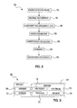
- the mandrels are removed at step 42 if they comprise permanent tooling. Otherwise the fugitive foam mandrels are left in place, and the entire sandwich assembly is post-cured at elevated temperatures, as shown at step 44. Depending on the type of rigid foam used as the mandrel tool, the elevated temperatures during the post-curing step 44 may be sufficient to incinerate the mandrel tools. Subsequently, non-destructive inspection techniques such as thermography or CT scanning can be used at step 46 (see Figure 7 ) to verify that the facesheets 12, 14 do not contain delaminations, and that good adhesion has been obtained between the flute members 18.
- non-destructive inspection techniques such as thermography or CT scanning can be used at step 46 (see Figure 7 ) to verify that the facesheets 12, 14 do not contain delaminations, and that good adhesion has been obtained between the flute members 18.
- a CMC structure 10a is to be fabricated having curved sections
- appropriate layup tooling (not shown) may be provided for forming the facesheets 12a, 14a into the desired shapes.
- the flute members 18 may be filled with a flexible, organic fugitive foam mandrel (not shown) so that the flute members 18 conform to the curved shape of the facesheets 12a, 14a.
- the fugitive foam mandrel may be either be washed out or pyrolyzed during the CMC post curing step 44.
- exemplary method 50 may include specification and design 52 of the aircraft 80 and material procurement 54.
- component and subassembly manufacturing 56 and system integration 58 of the aircraft 76 takes place.
- the aircraft 80 may go through certification and delivery 60 in order to be placed in service 62.
- routine maintenance and service 64 which may include modification, reconfiguration, refurbishment, and so on).
- a system integrator may include without limitation any number of aircraft manufacturers and major-system subcontractors; a third party may include without limitation any number of venders, subcontractors, and suppliers; and an operator may be an airline, leasing company, military entity, service organization, and so on.
- the aircraft 80 produced by exemplary method may include an airframe 92 with a plurality of systems 68 and an interior 70.
- high-level systems 68 include one or more of a propulsion system 72, an electrical system 74, a hydraulic system 76, and an environmental system 78. Any number of other systems may be included.
- an aerospace example is shown, the principles of the invention may be applied to other industries, such as the automotive industry. Apparatus and methods embodied herein may be employed during any one or more of the stages of the production and service method 50.
- components or subassemblies corresponding to production process 56 may be fabricated or manufactured in a manner similar to components or subassemblies produced while the aircraft 80 is in service.
- one or more apparatus embodiments, method embodiments, or a combination thereof may be utilized during the production stages 56 and 58, for example, by substantially expediting assembly of or reducing the cost of an aircraft 80.
- one or more of apparatus embodiments, method embodiments, or a combination thereof may be utilized while the aircraft 80 is in service, for example and without limitation, to maintenance and service 64.
Abstract
Description
- This disclosure generally relates to ceramic matrix composite structures, and deals more particularly with a sandwich construction having a load-carrying fluted core, as well as a method for making the structure.
- Ceramic matrix composite (CMC) structures are often used in aerospace and other applications because of their ability to withstand relatively high operating temperatures. For example, CMC structures may be used to fabricate parts subjected to high temperature exhaust gases in aircraft applications. Various CMC's have been employed to fabricate either monocoque structures or structures that employ a combination of tile and/or foam sandwich constructions, but neither of these types of structures may be well suited for carrying loads. In the case of CMC monocoques, the materials must be relatively thick in order for the structure to carry a load, but the additional material thickness adds weight to the aircraft. CMC tile/foam sandwich materials have not been widely used in load carrying applications, in part because of their relatively weak core materials.
- Accordingly, there is a need for a CMC structure that is relatively light weight, but yet has sufficient structural strength to be self-supporting and capable of carrying loads. It would also be desirable to provide a CMC structure that may be formed into various shapes, including those possessing curvature. Additionally, it would be desirable to provide a simple, cost effective method of fabricating these CMC structures. Embodiments of the disclosure are intended to satisfy these needs.
- Embodiments of the disclosure provide a CMC sandwich construction that allows fabrication of structures having various geometries, including curved surfaces and reinforced features that allow the structures to be mounted using the fasteners. The disclosed embodiments employ a CMC sandwich incorporating a fluted core formed of a CMC that strengthens the structure and allows it to carry loads. The CMC fluted core structure may be fabricated using commercially available materials and well known polymer layup techniques to produce a wide variety of parts, components and assemblies, especially those used in the aircraft industry.
- According to one disclosed embodiment, a ceramic matrix composite structure is provided, comprising a pair of spaced apart, CMC facesheets, and a load carrying core between at least a portion of the facesheets, wherein the core includes CMC flute members. The flute members may form a closed cell that may or may not be filled with any of a variety of high temperature materials. The flute members may be formed of ceramic matrix composite material having a wall cross section in the shape of an isosceles trapezoid, or other geometric shape. The flute members are arranged in side-by-side, nested relationship between the CMC facesheets.
- According to another embodiment, a CMC sandwich is provided, comprising a pair of spaced apart, CMC facesheets, and a plurality of CMC flutes between at least a portion of the facesheets for transmitting compression and shear loads between the facesheets. The facesheets may include both flat and curved sections, and the flutes may include walls conforming to the curvature of the facesheets. Portions of the facesheets may be directly laminated together to provide a reinforced structural area suitable for being pierced by mounting fasteners.
- According to a method embodiment of the disclosure, CMC structures may be fabricated by a method comprising the steps of: forming a plurality of flutes using a CMC; placing the flutes between a pair of CMC facesheets; and, bonding the flutes to the facesheets. The flutes may be formed by wrapping ceramic matrix prepreg fabric over a tool and then curing the prepreg. The tool may be either a permanent tool that is later removed, or a rigid, fugitive foam.
- According to another method embodiment, a CMC sandwich for use in aerospace structures may be fabricated by a method comprising the steps of: forming a load carrying structural core using CMC material; placing the core between a pair of CMC facesheets, and fusing the facesheets with the core. The core may be formed by fabricating a plurality of flutes, placing the flutes in nested, side-by-side relationship, and then laminating the flutes between the facesheets.
- According to another embodiment a ceramic matrix composite sandwich is disclosed, comprising:
- a pair of spaced apart, ceramic matrix composite facesheets; and,
- a plurality of ceramic matrix composite flutes between at least a portion of the facesheets for carrying compression and shear loads between the facesheets.
- According to a further embodiment of the invention each of the flutes includes four walls forming substantially an isosceles trapezoid in cross section.
- According to a further embodiment of the invention the facesheets include a flat section and a curved section, and the flutes include walls conforming to the curvature of the facesheets in the curved section.
- According to a further embodiment of the invention the flutes are filled with a rigid ceramic foam.
- The facesheets may be laminated together according to a further embodiment of the invention.
- The ceramic matrix composite sandwich further may comprise a solid ceramic core bonded between a portion of the facesheets.
- According to a further embodiment of the invention each of the flutes includes:
- a first pair of spaced apart walls respectively engaging the facesheets, and
- a second part of spaced apart walls connected to the first pair of walls and extending between the facesheets.
- According to a further embodiment of the invention the flutes are nested together and include voids therebetween, and the core further includes foam insulation filling the space between the first and second composite sheets.
- The invention also discloses a method of fabricating a ceramic matrix composite structure, comprising the steps of:
- (A) forming a plurality of flutes using a ceramic matrix composite;
- (B) placing the flutes formed in step (A) between a pair of ceramic matrix composite facesheets; and
- (C) bonding the flutes to the facesheets.
- The method further comprising may comprise the step of:
- (D) designing an aircraft assembly incorporating the structure.
- In addition, the method may comprise the step of:
- (D) procuring the material used to fabricate the structure.
- According to a further embodiment the method of fabricating a ceramic matrix composite structure the fabricating of the structure may form part of an operation for manufacturing an aircraft assembly.
- The invention further discloses an aircraft assembly using the structure fabricated according to the method of fabricating a ceramic matrix composite structure.
- Also a method of fabricating a ceramic matrix composite sandwich for use in aerospace structures is disclosed, comprising the steps of:
- (A) forming a load bearing structural core using ceramic matrix composite material;
- (B) placing the core between a pair of ceramic matrix composite facesheets; and,
- (C) fusing the facesheets with the core.
- According to a further embodiment in the in the aforementioned method step (A) may include fabricating a plurality of flutes, and placing the flutes in side-by-side relationship.
- Also a method of fabricating a ceramic matrix composite sandwich for use in aerospace structures is disclosed wherein the flutes are fabricated by wrapping ceramic matrix prepreg over a tool, and curing the prepreg.
- According to a further embodiment step (A) includes placing fillers in voids between the face sheets and the core.
- According to a further embodiment step (C) is performed by co-curing the core and the facesheets.
- Other features, benefits and advantages of the disclosed embodiments will become apparent from the following description of embodiments, when viewed in accordance with the attached drawings and appended claims. In the drawings:
- Figure 1
- is a perspective illustration of a CMC sandwich according to one embodiment.
- Figure 2
- is an enlarged, cross sectional illustration of a portion of the sandwich shown in
Figure 1 . - Figure 3
- is a perspective illustration showing a section of another embodiment of a CMC structure, incorporating both curved and flat sections.
- Figure 4
- is a cross sectional illustration of the CMC structure shown in
Figure 3 . - Figure 5
- is a cross sectional illustration of the area designated as "A" in
Figure 4 . - Figure 6
- is a cross sectional illustration of the area designated as "B" in
Figure 4 . - Figure 7
- is a simplified block diagram illustrating the steps of a method for fabricating a CMC structure.
- Figure 8
- is a flow diagram of an aircraft production and service methodology.
- Figure 9
- is a block diagram of an aircraft.
- Referring first to
Figures 1 and 2 , aCMC structure 10 is formed from a sandwich of materials comprising an inner, load carryingcore 16 sandwiched between a pair of outer,CMC facesheets facesheets - Each of the
facesheets - The
load carrying core 16 may function to transmit compressive, tensile and shear loads between thefacesheets CMC structure 10 to be both self-supporting and load carrying. TheCMC structure 10 is particularly well suited to high temperature applications since all of the composite materials in theCMC structure 10 are ceramic-based. Thecore 16 comprises a plurality ofelongate flute members 18 which are bonded together in nested, side-by-side relationship between thefacesheets flute members 18 may be hollow, or may be filled with any of a variety of ceramic materials, including, without limitation, rigid ceramic tile or foam, ceramic felt, other fibrous ceramic insulation (soft or rigid), monolithic ceramics, etc. - One rigid foam suitable for use in filling the
flute members 18 is disclosed inUS Patent 6,716,782 which is fully incorporated by reference. The rigid foam insulation described in this prior patent is a combination of ceramic fibers which are sintered together to form a low density, highly porous material with low thermal conductivity. This foam exhibits high tensile strength and good dimensional stability. As used herein, "high temperature" material is generally intended to refer to temperatures above which polymeric materials exhibit diminished capacity. - In the particular embodiment illustrated in
Figures 1 and 2 , theflute members 18 includewalls flute members 18 may vary from one end of theCMC structure 10 to the other. The flute members may extend in the direction of the length and/or the width of theCMC structure 10, depending on the application and the load requirements. - The
walls facesheets Figure 2 , one pair of thewalls 18a of theflute member 18 extend parallel to each other and are bonded to thefacesheets walls 18b are inclined in opposite directions and extend transverse to thefacesheets facesheets - The
walls 18b ofadjacent flute members 18 may be bonded together in face-to-face contact. The intersection ofadjacent flute members 18 andfacesheets fillers 20 in the form of elongate "noodles" that have a cross sectional shape matching that of the void; in the illustrated example, the voids, and thenoodle fillers 20 are triangular in cross section. Thenoodle fillers 20 may be made with CMC prepreg, tape, tows, or filaments, and function to more evenly distribute and transmit loads between thefacesheets - Referring now to
Figures 3-6 an alternateembodiment CMC structure 10a includes first andsecond CMC facesheets section 15 of theCMC structure 10a includes a fluted core defined byflute members 18a having cavities 20a which may or may not be filled with a suitable low density, high temperature rigid foam such as a ceramic foam previously described. Unlike theCMC structure 10 shown inFigures 1 and 2 ,section 15 in theCMC structure 10a is curved. Accordingly, theflute members 18a have top andbottom walls 18c (Figure 5 ) that may be slightly curved to match the curvature offacesheets structure 12a, thefacesheets solid section 22 of theCMC structure 10a. A ceramic structural member, such as a solidceramic insert 26 may be sandwiched betweenfacesheets solid section 22 of thestructure 10a to provide additional strength and stiffness. Thesolid section 22 provides a reinforced area having sufficient strength and stiffness to allow fasteners (not shown) to pierce thestructure 10a in order to attach thestructure 10a. - Multiple flat or
curved structures Figure 4 in which thefacesheets female socket 25 that receives a solidmale projection 27 forming part of anadjacent structure - A method for fabricating the
structures Figure 7 . Beginning atstep 30, theflute members 18 are formed by wrapping one or more plies of CMC prepreg or tape around or over a mandrel tool (not shown). The tool may comprise, without limitation, solid metal, permanent tooling, or a rigid foam member which may or may not be fugitive, but possesses the shape of theflute member 18 to be formed. The mandrel tool may be formed of other materials such as ceramic tile, ceramic foam or organically rigidized ceramic batting. - Next, at
step 32, the wrappedflute members 18 are assembled together by nesting them in side-by-side relationship, following which the assembledflute members 18 are cured atstep 34 normally at elevated temperature and pressure. Atstep 36, theprepreg noodle fillers 20 are installed in the voids betweenadjacent flute members 18. - At
step 38, thefacesheets flute members 18, and the resulting sandwich assembly is then cured in the normal manner which may involve, for example, placing the sandwich assembly in an autoclave (not shown). Thefacesheets - Following the curing step at 40, the mandrels are removed at
step 42 if they comprise permanent tooling. Otherwise the fugitive foam mandrels are left in place, and the entire sandwich assembly is post-cured at elevated temperatures, as shown atstep 44. Depending on the type of rigid foam used as the mandrel tool, the elevated temperatures during thepost-curing step 44 may be sufficient to incinerate the mandrel tools. Subsequently, non-destructive inspection techniques such as thermography or CT scanning can be used at step 46 (seeFigure 7 ) to verify that thefacesheets flute members 18. - Where a
CMC structure 10a is to be fabricated having curved sections, appropriate layup tooling (not shown) may be provided for forming thefacesheets flute members 18 may be filled with a flexible, organic fugitive foam mandrel (not shown) so that theflute members 18 conform to the curved shape of thefacesheets post curing step 44. - The embodiments of the disclosure described above may be described in the context of an aircraft manufacturing and
service method 50 as shown inFigure 8 and anaircraft 80 as shown inFigure 9 . During pre-production,exemplary method 50 may include specification anddesign 52 of theaircraft 80 andmaterial procurement 54. During production, component andsubassembly manufacturing 56 andsystem integration 58 of theaircraft 76 takes place. Thereafter, theaircraft 80 may go through certification anddelivery 60 in order to be placed inservice 62. While in service by a customer, theaircraft 80 is scheduled for routine maintenance and service 64 (which may include modification, reconfiguration, refurbishment, and so on). - Each of the processes of
method 50 may be performed or carried out by a system integrator, a third party, and/or an operator (e.g., a customer). For the purposes of this description, a system integrator may include without limitation any number of aircraft manufacturers and major-system subcontractors; a third party may include without limitation any number of venders, subcontractors, and suppliers; and an operator may be an airline, leasing company, military entity, service organization, and so on. - As shown in
Figure 9 , theaircraft 80 produced by exemplary method may include an airframe 92 with a plurality ofsystems 68 and an interior 70. Examples of high-level systems 68 include one or more of apropulsion system 72, anelectrical system 74, ahydraulic system 76, and anenvironmental system 78. Any number of other systems may be included. Although an aerospace example is shown, the principles of the invention may be applied to other industries, such as the automotive industry. Apparatus and methods embodied herein may be employed during any one or more of the stages of the production andservice method 50. For example, components or subassemblies corresponding toproduction process 56 may be fabricated or manufactured in a manner similar to components or subassemblies produced while theaircraft 80 is in service. Also, one or more apparatus embodiments, method embodiments, or a combination thereof may be utilized during the production stages 56 and 58, for example, by substantially expediting assembly of or reducing the cost of anaircraft 80. Similarly, one or more of apparatus embodiments, method embodiments, or a combination thereof may be utilized while theaircraft 80 is in service, for example and without limitation, to maintenance andservice 64. - Although the embodiments of this disclosure have been described with respect to certain exemplary embodiments, it is to be understood that the specific embodiments are for purposes of illustration and not limitation, as other variations will occur to those of skill in the art.
Claims (15)
- A ceramic matrix composite structure, comprising:a pair of spaced apart, ceramic matrix composite facesheets (12, 12a, 14, 14a);
and,a load carrying core (16) between at least a portion of the facesheets (12, 12a, 14, 14a), the load carrying core (16) including ceramic matrix composite flutes (18, 18a). - The ceramic composite structure of claim 1, wherein:at least certain of the flutes (18, 18a) include a closed cell filled with ceramic foam (20, 20a).
- The ceramic composite structure of claim 2, wherein the cell includes a continuous wall (18, 18a, b, c) defined by compacted multiple plies of ceramic fiber reinforced resin.
- The ceramic composite structure of any of claims 1 to 3, wherein each of the facesheets (12, 12a, 14, 14a) includes compacted multiple plies of ceramic fiber reinforced resin.
- The ceramic composite structure of any of claims 1 to 4, wherein:the flutes (18, 18a) are arranged in side-by-side relationship and define voids therebetween, andthe core (16) further includes filler strips (20, 20a) filling the voids.
- The ceramic composite structure of any of the preceding claims, wherein:at least a section of each of the facesheets (12, 12a) is curved, andthe flutes (18a) conform to the curvature of the facesheet section.
- The ceramic composite structure of any of the preceding claims, further comprising a solid structural core (16) between another portion of the facesheets (12, 12a, 14, 14a).
- The ceramic composite structure of any of the preceding claims, wherein each of the flutes (18, 18a) has a cross sectional shape forming substantially an isosceles trapezoid.
- A method of fabricating a ceramic matrix composite structure (10, 10a), comprising the steps of:(A) forming a plurality of flutes (18, 18a) using a ceramic matrix composite;(B) placing the flutes (18, 18a) formed in step (A) between a pair of ceramic matrix composite facesheets (12, 12a, 14, 14a); and(C) bonding the flutes (18, 18a) to the facesheets (12, 12a, 14, 14a).
- The method of claim 9, wherein step (A) includes at least one of the following steps:- wrapping ceramic matrix prepreg fabric over a tool, and curing the prepreg;- forming the tool by shaping a rigid foam into a mandrel;- incinerating the foam after the prepreg has been cured.
- The method of claim 9 or 10, wherein step (A) includes:arranging the flutes (18, 18a) in side-by-side nested relationship, andcuring the arranged flutes (18, 18a).
- The method of any of claims 9 to 11, further comprising the step of installing filler (20, 20a) in voids between adjacent flutes (18, 18a) and the facesheets (12, 12a, 14, 14a).
- The method of any of claims 9 to 12, further comprising the step of:(D) laminating together portions of the facesheets (12, 12a, 14, 14a).
- The method of any of claims 9 to 13, further comprising the steps of:(D) placing a solid ceramic core (16) between a portion of the facesheets (12, 12a, 14, 14a); and,(E) bonding the portion of facesheets (12, 12a, 14, 14a) to the ceramic core (16).
- The method of any of claims 9 to 14, wherein step (C) is performed by co-curing the facesheets (12, 12a, 14, 14a) and the flutes (18, 18a).
Applications Claiming Priority (1)
| Application Number | Priority Date | Filing Date | Title |
|---|---|---|---|
| US11/770,035 US20090004425A1 (en) | 2007-06-28 | 2007-06-28 | Ceramic Matrix Composite Structure having Fluted Core and Method for Making the Same |
Publications (3)
| Publication Number | Publication Date |
|---|---|
| EP2008807A2 true EP2008807A2 (en) | 2008-12-31 |
| EP2008807A3 EP2008807A3 (en) | 2010-12-22 |
| EP2008807B1 EP2008807B1 (en) | 2018-08-29 |
Family
ID=39789663
Family Applications (1)
| Application Number | Title | Priority Date | Filing Date |
|---|---|---|---|
| EP08158706.5A Active EP2008807B1 (en) | 2007-06-28 | 2008-06-20 | Ceramic matrix composite structure having fluted core and method of making the same |
Country Status (7)
| Country | Link |
|---|---|
| US (1) | US20090004425A1 (en) |
| EP (1) | EP2008807B1 (en) |
| JP (1) | JP2009113470A (en) |
| CN (1) | CN101332689A (en) |
| AU (1) | AU2008202327A1 (en) |
| CA (1) | CA2633393C (en) |
| ES (1) | ES2699409T3 (en) |
Cited By (6)
| Publication number | Priority date | Publication date | Assignee | Title |
|---|---|---|---|---|
| WO2009131793A1 (en) * | 2008-04-21 | 2009-10-29 | The Boeing Company | Exhaust washed structure and associated composite structure and method of fabrication |
| FR2936181A1 (en) * | 2008-09-24 | 2010-03-26 | Lorraine De Construction Aeron | REINFORCED COMPOSITE SANDWICH PANEL |
| EP2457824A1 (en) * | 2010-11-29 | 2012-05-30 | Airbus Operations Ltd | An aircraft structure |
| WO2019060093A1 (en) * | 2017-09-19 | 2019-03-28 | Hexcel Corporation | Thermal panel |
| EP3476561A1 (en) * | 2017-10-31 | 2019-05-01 | Airbus Operations, S.L. | Modular mould and method for manufacturing a panel of fibre reinforced material |
| FR3135648A1 (en) * | 2022-05-19 | 2023-11-24 | Irt Antoine De Saint Exupéry | CYLINDRICAL PART WITH SANDWICH STRUCTURE, METHOD FOR MANUFACTURING SUCH A PART AND ITS USE FOR THE STORAGE OF RADIOACTIVE WASTE |
Families Citing this family (31)
| Publication number | Priority date | Publication date | Assignee | Title |
|---|---|---|---|---|
| US9586699B1 (en) | 1999-08-16 | 2017-03-07 | Smart Drilling And Completion, Inc. | Methods and apparatus for monitoring and fixing holes in composite aircraft |
| US9625361B1 (en) | 2001-08-19 | 2017-04-18 | Smart Drilling And Completion, Inc. | Methods and apparatus to prevent failures of fiber-reinforced composite materials under compressive stresses caused by fluids and gases invading microfractures in the materials |
| US8626478B1 (en) | 2010-07-16 | 2014-01-07 | The Boeing Company | Cross flow parameter calculation for aerodynamic analysis |
| US8980435B2 (en) * | 2011-10-04 | 2015-03-17 | General Electric Company | CMC component, power generation system and method of forming a CMC component |
| US9663404B2 (en) * | 2012-01-03 | 2017-05-30 | General Electric Company | Method of forming a ceramic matrix composite and a ceramic matrix component |
| US9034465B2 (en) * | 2012-06-08 | 2015-05-19 | United Technologies Corporation | Thermally insulative attachment |
| JP5920979B2 (en) * | 2012-07-04 | 2016-05-24 | 日本飛行機株式会社 | Aircraft components |
| US8894919B1 (en) | 2012-07-18 | 2014-11-25 | The Boeing Company | Method for incorporation of insulators and bulk absorbers in high temperature sandwich structures after fabrication |
| BR112015008010A2 (en) * | 2012-10-12 | 2017-07-04 | Solvay Specialty Polymers Usa | high temperature sulfone foam materials (hts) |
| US10308343B2 (en) * | 2013-05-30 | 2019-06-04 | The Boeing Company | Composite hat stiffener |
| US20150314545A1 (en) * | 2014-05-05 | 2015-11-05 | The Boeing Company | Aircraft Foam Insulation Method and Apparatus |
| US9850173B2 (en) | 2015-01-09 | 2017-12-26 | The Boeing Company | Hybrid sandwich ceramic matrix composite |
| US9770864B2 (en) * | 2015-06-10 | 2017-09-26 | The Boeing Company | Methods of internally insulating a fluted core sandwich structure |
| US9878809B2 (en) * | 2015-06-12 | 2018-01-30 | The Boeing Company | Stand-off panel thermal protection system and method of fabricating the same |
| CN106315060A (en) * | 2015-06-18 | 2017-01-11 | 廖树汉 | Acid-alkali-corrosion-resistant and impact-resistant sine-wave foam-wall ceramic petroleum tank with service life of thousand years |
| CN106315059A (en) * | 2015-06-18 | 2017-01-11 | 廖树汉 | Acid-alkali-corrosion-resistant and impact-resistant corrugated-wall enamel-glass petroleum tank with service life of hundred years |
| CN106241097A (en) * | 2015-06-18 | 2016-12-21 | 廖树汉 | The string ripple foam wall enamel Oil Tank that the antiacid caustic corrosion impact resistant life-span is century-old |
| CN106315041A (en) * | 2015-06-18 | 2017-01-11 | 廖树汉 | Acid-alkali-corrosion-resistant and impact-resistant sine-wave foam-wall vitreous enamel petroleum tank with service life of thousand years |
| CN106256712A (en) * | 2015-06-18 | 2016-12-28 | 廖树汉 | The foam wall ceramic stone oil tank in antiacid thousand caustic corrosion impact resistant life-spans |
| CN106315057A (en) * | 2015-06-18 | 2017-01-11 | 廖树汉 | Acid and alkali corrosion-resistant collision-resistant corrugated walled ceramic glass petroleum tank |
| CN106315058A (en) * | 2015-06-18 | 2017-01-11 | 廖树汉 | Acid-alkali-corrosion-resistant and impact-resistant foam-wall ceramics-glass petroleum tank with service life of thousand years |
| US10207471B2 (en) * | 2016-05-04 | 2019-02-19 | General Electric Company | Perforated ceramic matrix composite ply, ceramic matrix composite article, and method for forming ceramic matrix composite article |
| CN107584834A (en) * | 2016-07-08 | 2018-01-16 | 中国航空工业集团公司济南特种结构研究所 | A kind of high temperature resistant foam core material |
| JP7050458B2 (en) * | 2017-02-14 | 2022-04-08 | ザ・ボーイング・カンパニー | How to assemble a composite core sandwich edge joint |
| CN108640698A (en) * | 2018-05-02 | 2018-10-12 | 中国航发北京航空材料研究院 | A kind of ceramic base composite material member co-curing moulding process |
| CN109436099B (en) * | 2018-09-19 | 2021-07-09 | 中国第一汽车股份有限公司 | Regular polygon uniform-section anti-collision structure applied to composite material automobile threshold |
| EP3674081B1 (en) * | 2018-12-31 | 2022-02-23 | Ansaldo Energia Switzerland AG | High-temperature resistant tiles and manufacturing method thereof |
| JP7332784B2 (en) | 2020-03-05 | 2023-08-23 | 富士フイルム株式会社 | Radiation detector and radiographic imaging device |
| US20210339515A1 (en) * | 2020-05-02 | 2021-11-04 | Hamilton Sundstrand Corporation | Ceramic matrix composite laminate tube sheet and method for making the same |
| GB2620459A (en) * | 2022-07-06 | 2024-01-10 | Darchem Engineering Ltd | Enclosure |
| GB2606481A (en) * | 2022-07-06 | 2022-11-09 | Darchem Engineering Ltd | Enclosure |
Citations (2)
| Publication number | Priority date | Publication date | Assignee | Title |
|---|---|---|---|---|
| US5372868A (en) | 1990-05-31 | 1994-12-13 | United Technologies Corporation | Fiber reinforced glass matrix and glass-ceramic matrix composite articles |
| US5632834A (en) | 1990-09-27 | 1997-05-27 | Dornier Gmbh | Process for producing sandwich structures from fiber-reinforced ceramics |
Family Cites Families (19)
| Publication number | Priority date | Publication date | Assignee | Title |
|---|---|---|---|---|
| US4016229A (en) * | 1973-11-19 | 1977-04-05 | Grumman Aerospace Corporation | Closed-cell ceramic foam material |
| US4122047A (en) * | 1977-03-04 | 1978-10-24 | Isaac Meisels | Production of polyester foam |
| US4789594A (en) * | 1987-04-15 | 1988-12-06 | The Boeing Company | Method of forming composite radius fillers |
| US4822660A (en) * | 1987-06-02 | 1989-04-18 | Corning Glass Works | Lightweight ceramic structures and method |
| EP0294176A3 (en) * | 1987-06-02 | 1989-12-27 | Corning Glass Works | Lightweight laminated or composite structures |
| US5488017A (en) * | 1989-04-14 | 1996-01-30 | General Electric Company | Fibert reinforced ceramic matrix composite member |
| US5225015A (en) * | 1991-04-15 | 1993-07-06 | Corning Incorporated | Method for making stiffened ceramic matrix composite panel |
| US5338594A (en) * | 1992-02-07 | 1994-08-16 | Hexcel Corporation | Foam filled honeycomb and methods for their production |
| US5469686A (en) * | 1993-09-27 | 1995-11-28 | Rockwell International Corp. | Composite structural truss element |
| JP4009921B2 (en) * | 1999-03-16 | 2007-11-21 | 東レ株式会社 | FRP sandwich panel |
| US6743504B1 (en) * | 2001-03-01 | 2004-06-01 | Rohr, Inc. | Co-cured composite structures and method of making them |
| US6746755B2 (en) * | 2001-09-24 | 2004-06-08 | Siemens Westinghouse Power Corporation | Ceramic matrix composite structure having integral cooling passages and method of manufacture |
| US6830437B2 (en) * | 2002-12-13 | 2004-12-14 | General Electric Company | Assembly containing a composite article and assembly method therefor |
| US6969546B2 (en) * | 2003-10-20 | 2005-11-29 | The Boeing Company | Thermal insulation system employing oxide ceramic matrix composites |
| US7312274B2 (en) * | 2003-11-24 | 2007-12-25 | General Electric Company | Composition and method for use with ceramic matrix composite T-sections |
| DE102004001080A1 (en) * | 2004-01-05 | 2005-08-04 | Airbus Deutschland Gmbh | Arrangement for the interior lining of a passenger cabin of an aircraft |
| US7600979B2 (en) * | 2006-11-28 | 2009-10-13 | General Electric Company | CMC articles having small complex features |
| US8097106B2 (en) * | 2007-06-28 | 2012-01-17 | The Boeing Company | Method for fabricating composite structures having reinforced edge bonded joints |
| US9782951B2 (en) * | 2007-07-18 | 2017-10-10 | The Boeing Company | Composite structure having ceramic truss core and method for making the same |
-
2007
- 2007-06-28 US US11/770,035 patent/US20090004425A1/en not_active Abandoned
-
2008
- 2008-05-27 AU AU2008202327A patent/AU2008202327A1/en not_active Abandoned
- 2008-06-04 CA CA2633393A patent/CA2633393C/en active Active
- 2008-06-20 EP EP08158706.5A patent/EP2008807B1/en active Active
- 2008-06-20 ES ES08158706T patent/ES2699409T3/en active Active
- 2008-06-26 CN CNA2008101305139A patent/CN101332689A/en active Pending
- 2008-06-30 JP JP2008170617A patent/JP2009113470A/en active Pending
Patent Citations (2)
| Publication number | Priority date | Publication date | Assignee | Title |
|---|---|---|---|---|
| US5372868A (en) | 1990-05-31 | 1994-12-13 | United Technologies Corporation | Fiber reinforced glass matrix and glass-ceramic matrix composite articles |
| US5632834A (en) | 1990-09-27 | 1997-05-27 | Dornier Gmbh | Process for producing sandwich structures from fiber-reinforced ceramics |
Cited By (14)
| Publication number | Priority date | Publication date | Assignee | Title |
|---|---|---|---|---|
| US8043690B2 (en) | 2008-04-21 | 2011-10-25 | The Boeing Company | Exhaust washed structure and associated composite structure and method of fabrication |
| WO2009131793A1 (en) * | 2008-04-21 | 2009-10-29 | The Boeing Company | Exhaust washed structure and associated composite structure and method of fabrication |
| US8192570B2 (en) | 2008-04-21 | 2012-06-05 | The Boeing Company | Exhaust washed structure and associated composite structure and method of fabrication |
| US8474573B2 (en) | 2008-09-24 | 2013-07-02 | Societe Lorraine De Construction Aeronautique | Reinforced composite sandwich panel |
| FR2936181A1 (en) * | 2008-09-24 | 2010-03-26 | Lorraine De Construction Aeron | REINFORCED COMPOSITE SANDWICH PANEL |
| US9701391B2 (en) | 2010-11-29 | 2017-07-11 | Airbus Operations Limited | Aircraft structure comprising a skin panel |
| EP2457824A1 (en) * | 2010-11-29 | 2012-05-30 | Airbus Operations Ltd | An aircraft structure |
| WO2019060093A1 (en) * | 2017-09-19 | 2019-03-28 | Hexcel Corporation | Thermal panel |
| CN111107989A (en) * | 2017-09-19 | 2020-05-05 | 赫克赛尔公司 | Heat insulation board |
| CN111107989B (en) * | 2017-09-19 | 2021-05-25 | 赫克赛尔公司 | Heat insulation board |
| EP3476561A1 (en) * | 2017-10-31 | 2019-05-01 | Airbus Operations, S.L. | Modular mould and method for manufacturing a panel of fibre reinforced material |
| US10899091B2 (en) | 2017-10-31 | 2021-01-26 | Airbus Operations S.L. | Modular mold and method for manufacturing a panel of fiber reinforced material |
| RU2760387C2 (en) * | 2017-10-31 | 2021-11-24 | Эйрбас Оперейшнз, С.Л. | Modular mould and method for manufacturing a panel from a fibre-reinforced material |
| FR3135648A1 (en) * | 2022-05-19 | 2023-11-24 | Irt Antoine De Saint Exupéry | CYLINDRICAL PART WITH SANDWICH STRUCTURE, METHOD FOR MANUFACTURING SUCH A PART AND ITS USE FOR THE STORAGE OF RADIOACTIVE WASTE |
Also Published As
| Publication number | Publication date |
|---|---|
| CA2633393C (en) | 2012-04-03 |
| AU2008202327A1 (en) | 2009-01-15 |
| JP2009113470A (en) | 2009-05-28 |
| ES2699409T3 (en) | 2019-02-11 |
| CN101332689A (en) | 2008-12-31 |
| US20090004425A1 (en) | 2009-01-01 |
| EP2008807B1 (en) | 2018-08-29 |
| EP2008807A3 (en) | 2010-12-22 |
| CA2633393A1 (en) | 2008-12-28 |
Similar Documents
| Publication | Publication Date | Title |
|---|---|---|
| CA2633393C (en) | Ceramic matrix composite structure having fluted core and method of making the same | |
| US8097106B2 (en) | Method for fabricating composite structures having reinforced edge bonded joints | |
| US8512853B2 (en) | Composite structure having reinforced core | |
| US8642168B2 (en) | Composite structure having reinforced core and method of making the same | |
| EP2790898B1 (en) | Composite strut and fabrication method | |
| EP2349685B1 (en) | Composite truss panel having fluted core and stiffener made of foam and method for making the same | |
| EP3117984B1 (en) | Process for manufacturingmulti-functional aircraft structure | |
| EP2017073B1 (en) | Composite structure having ceramic truss core and method for making the same | |
| KR20140055993A (en) | Composite radius fillers and method of forming the same | |
| CA2769693A1 (en) | Method of molding complex composite parts using pre-plied multi-directional continuous fiber laminate | |
| US10457011B2 (en) | Composite columnar structure having co-bonded reinforcement and fabrication method | |
| US7371451B2 (en) | Sandwich type construction structural panel having foam tube core | |
| Heidenreich et al. | C/C–SiC sandwich structures manufactured via liquid silicon infiltration |
Legal Events
| Date | Code | Title | Description |
|---|---|---|---|
| PUAI | Public reference made under article 153(3) epc to a published international application that has entered the european phase |
Free format text: ORIGINAL CODE: 0009012 |
|
| AK | Designated contracting states |
Kind code of ref document: A2 Designated state(s): AT BE BG CH CY CZ DE DK EE ES FI FR GB GR HR HU IE IS IT LI LT LU LV MC MT NL NO PL PT RO SE SI SK TR |
|
| AX | Request for extension of the european patent |
Extension state: AL BA MK RS |
|
| PUAL | Search report despatched |
Free format text: ORIGINAL CODE: 0009013 |
|
| AK | Designated contracting states |
Kind code of ref document: A3 Designated state(s): AT BE BG CH CY CZ DE DK EE ES FI FR GB GR HR HU IE IS IT LI LT LU LV MC MT NL NO PL PT RO SE SI SK TR |
|
| AX | Request for extension of the european patent |
Extension state: AL BA MK RS |
|
| 17P | Request for examination filed |
Effective date: 20110616 |
|
| AKX | Designation fees paid |
Designated state(s): AT BE BG CH CY CZ DE DK EE ES FI FR GB GR HR HU IE IS IT LI LT LU LV MC MT NL NO PL PT RO SE SI SK TR |
|
| 17Q | First examination report despatched |
Effective date: 20130408 |
|
| STAA | Information on the status of an ep patent application or granted ep patent |
Free format text: STATUS: EXAMINATION IS IN PROGRESS |
|
| GRAP | Despatch of communication of intention to grant a patent |
Free format text: ORIGINAL CODE: EPIDOSNIGR1 |
|
| STAA | Information on the status of an ep patent application or granted ep patent |
Free format text: STATUS: GRANT OF PATENT IS INTENDED |
|
| INTG | Intention to grant announced |
Effective date: 20180320 |
|
| GRAS | Grant fee paid |
Free format text: ORIGINAL CODE: EPIDOSNIGR3 |
|
| GRAA | (expected) grant |
Free format text: ORIGINAL CODE: 0009210 |
|
| STAA | Information on the status of an ep patent application or granted ep patent |
Free format text: STATUS: THE PATENT HAS BEEN GRANTED |
|
| AK | Designated contracting states |
Kind code of ref document: B1 Designated state(s): AT BE BG CH CY CZ DE DK EE ES FI FR GB GR HR HU IE IS IT LI LT LU LV MC MT NL NO PL PT RO SE SI SK TR |
|
| REG | Reference to a national code |
Ref country code: GB Ref legal event code: FG4D |
|
| REG | Reference to a national code |
Ref country code: CH Ref legal event code: EP |
|
| REG | Reference to a national code |
Ref country code: AT Ref legal event code: REF Ref document number: 1034641 Country of ref document: AT Kind code of ref document: T Effective date: 20180915 |
|
| REG | Reference to a national code |
Ref country code: IE Ref legal event code: FG4D |
|
| REG | Reference to a national code |
Ref country code: DE Ref legal event code: R096 Ref document number: 602008056674 Country of ref document: DE |
|
| REG | Reference to a national code |
Ref country code: NL Ref legal event code: MP Effective date: 20180829 |
|
| REG | Reference to a national code |
Ref country code: LT Ref legal event code: MG4D |
|
| PG25 | Lapsed in a contracting state [announced via postgrant information from national office to epo] |
Ref country code: LT Free format text: LAPSE BECAUSE OF FAILURE TO SUBMIT A TRANSLATION OF THE DESCRIPTION OR TO PAY THE FEE WITHIN THE PRESCRIBED TIME-LIMIT Effective date: 20180829 Ref country code: NO Free format text: LAPSE BECAUSE OF FAILURE TO SUBMIT A TRANSLATION OF THE DESCRIPTION OR TO PAY THE FEE WITHIN THE PRESCRIBED TIME-LIMIT Effective date: 20181129 Ref country code: IS Free format text: LAPSE BECAUSE OF FAILURE TO SUBMIT A TRANSLATION OF THE DESCRIPTION OR TO PAY THE FEE WITHIN THE PRESCRIBED TIME-LIMIT Effective date: 20181229 Ref country code: GR Free format text: LAPSE BECAUSE OF FAILURE TO SUBMIT A TRANSLATION OF THE DESCRIPTION OR TO PAY THE FEE WITHIN THE PRESCRIBED TIME-LIMIT Effective date: 20181130 Ref country code: BG Free format text: LAPSE BECAUSE OF FAILURE TO SUBMIT A TRANSLATION OF THE DESCRIPTION OR TO PAY THE FEE WITHIN THE PRESCRIBED TIME-LIMIT Effective date: 20181129 Ref country code: NL Free format text: LAPSE BECAUSE OF FAILURE TO SUBMIT A TRANSLATION OF THE DESCRIPTION OR TO PAY THE FEE WITHIN THE PRESCRIBED TIME-LIMIT Effective date: 20180829 Ref country code: FI Free format text: LAPSE BECAUSE OF FAILURE TO SUBMIT A TRANSLATION OF THE DESCRIPTION OR TO PAY THE FEE WITHIN THE PRESCRIBED TIME-LIMIT Effective date: 20180829 Ref country code: SE Free format text: LAPSE BECAUSE OF FAILURE TO SUBMIT A TRANSLATION OF THE DESCRIPTION OR TO PAY THE FEE WITHIN THE PRESCRIBED TIME-LIMIT Effective date: 20180829 |
|
| REG | Reference to a national code |
Ref country code: ES Ref legal event code: FG2A Ref document number: 2699409 Country of ref document: ES Kind code of ref document: T3 Effective date: 20190211 |
|
| REG | Reference to a national code |
Ref country code: AT Ref legal event code: MK05 Ref document number: 1034641 Country of ref document: AT Kind code of ref document: T Effective date: 20180829 |
|
| PG25 | Lapsed in a contracting state [announced via postgrant information from national office to epo] |
Ref country code: LV Free format text: LAPSE BECAUSE OF FAILURE TO SUBMIT A TRANSLATION OF THE DESCRIPTION OR TO PAY THE FEE WITHIN THE PRESCRIBED TIME-LIMIT Effective date: 20180829 Ref country code: HR Free format text: LAPSE BECAUSE OF FAILURE TO SUBMIT A TRANSLATION OF THE DESCRIPTION OR TO PAY THE FEE WITHIN THE PRESCRIBED TIME-LIMIT Effective date: 20180829 |
|
| PG25 | Lapsed in a contracting state [announced via postgrant information from national office to epo] |
Ref country code: RO Free format text: LAPSE BECAUSE OF FAILURE TO SUBMIT A TRANSLATION OF THE DESCRIPTION OR TO PAY THE FEE WITHIN THE PRESCRIBED TIME-LIMIT Effective date: 20180829 Ref country code: PL Free format text: LAPSE BECAUSE OF FAILURE TO SUBMIT A TRANSLATION OF THE DESCRIPTION OR TO PAY THE FEE WITHIN THE PRESCRIBED TIME-LIMIT Effective date: 20180829 Ref country code: AT Free format text: LAPSE BECAUSE OF FAILURE TO SUBMIT A TRANSLATION OF THE DESCRIPTION OR TO PAY THE FEE WITHIN THE PRESCRIBED TIME-LIMIT Effective date: 20180829 Ref country code: EE Free format text: LAPSE BECAUSE OF FAILURE TO SUBMIT A TRANSLATION OF THE DESCRIPTION OR TO PAY THE FEE WITHIN THE PRESCRIBED TIME-LIMIT Effective date: 20180829 Ref country code: CZ Free format text: LAPSE BECAUSE OF FAILURE TO SUBMIT A TRANSLATION OF THE DESCRIPTION OR TO PAY THE FEE WITHIN THE PRESCRIBED TIME-LIMIT Effective date: 20180829 |
|
| PG25 | Lapsed in a contracting state [announced via postgrant information from national office to epo] |
Ref country code: SK Free format text: LAPSE BECAUSE OF FAILURE TO SUBMIT A TRANSLATION OF THE DESCRIPTION OR TO PAY THE FEE WITHIN THE PRESCRIBED TIME-LIMIT Effective date: 20180829 Ref country code: DK Free format text: LAPSE BECAUSE OF FAILURE TO SUBMIT A TRANSLATION OF THE DESCRIPTION OR TO PAY THE FEE WITHIN THE PRESCRIBED TIME-LIMIT Effective date: 20180829 |
|
| REG | Reference to a national code |
Ref country code: DE Ref legal event code: R097 Ref document number: 602008056674 Country of ref document: DE |
|
| PLBE | No opposition filed within time limit |
Free format text: ORIGINAL CODE: 0009261 |
|
| STAA | Information on the status of an ep patent application or granted ep patent |
Free format text: STATUS: NO OPPOSITION FILED WITHIN TIME LIMIT |
|
| 26N | No opposition filed |
Effective date: 20190531 |
|
| PG25 | Lapsed in a contracting state [announced via postgrant information from national office to epo] |
Ref country code: SI Free format text: LAPSE BECAUSE OF FAILURE TO SUBMIT A TRANSLATION OF THE DESCRIPTION OR TO PAY THE FEE WITHIN THE PRESCRIBED TIME-LIMIT Effective date: 20180829 |
|
| PG25 | Lapsed in a contracting state [announced via postgrant information from national office to epo] |
Ref country code: MC Free format text: LAPSE BECAUSE OF FAILURE TO SUBMIT A TRANSLATION OF THE DESCRIPTION OR TO PAY THE FEE WITHIN THE PRESCRIBED TIME-LIMIT Effective date: 20180829 |
|
| REG | Reference to a national code |
Ref country code: CH Ref legal event code: PL |
|
| REG | Reference to a national code |
Ref country code: BE Ref legal event code: MM Effective date: 20190630 |
|
| PG25 | Lapsed in a contracting state [announced via postgrant information from national office to epo] |
Ref country code: TR Free format text: LAPSE BECAUSE OF FAILURE TO SUBMIT A TRANSLATION OF THE DESCRIPTION OR TO PAY THE FEE WITHIN THE PRESCRIBED TIME-LIMIT Effective date: 20180829 |
|
| PG25 | Lapsed in a contracting state [announced via postgrant information from national office to epo] |
Ref country code: IE Free format text: LAPSE BECAUSE OF NON-PAYMENT OF DUE FEES Effective date: 20190620 |
|
| PG25 | Lapsed in a contracting state [announced via postgrant information from national office to epo] |
Ref country code: CH Free format text: LAPSE BECAUSE OF NON-PAYMENT OF DUE FEES Effective date: 20190630 Ref country code: LI Free format text: LAPSE BECAUSE OF NON-PAYMENT OF DUE FEES Effective date: 20190630 Ref country code: BE Free format text: LAPSE BECAUSE OF NON-PAYMENT OF DUE FEES Effective date: 20190630 Ref country code: LU Free format text: LAPSE BECAUSE OF NON-PAYMENT OF DUE FEES Effective date: 20190620 |
|
| PG25 | Lapsed in a contracting state [announced via postgrant information from national office to epo] |
Ref country code: PT Free format text: LAPSE BECAUSE OF FAILURE TO SUBMIT A TRANSLATION OF THE DESCRIPTION OR TO PAY THE FEE WITHIN THE PRESCRIBED TIME-LIMIT Effective date: 20181229 |
|
| PG25 | Lapsed in a contracting state [announced via postgrant information from national office to epo] |
Ref country code: CY Free format text: LAPSE BECAUSE OF FAILURE TO SUBMIT A TRANSLATION OF THE DESCRIPTION OR TO PAY THE FEE WITHIN THE PRESCRIBED TIME-LIMIT Effective date: 20180829 |
|
| PG25 | Lapsed in a contracting state [announced via postgrant information from national office to epo] |
Ref country code: HU Free format text: LAPSE BECAUSE OF FAILURE TO SUBMIT A TRANSLATION OF THE DESCRIPTION OR TO PAY THE FEE WITHIN THE PRESCRIBED TIME-LIMIT; INVALID AB INITIO Effective date: 20080620 Ref country code: MT Free format text: LAPSE BECAUSE OF FAILURE TO SUBMIT A TRANSLATION OF THE DESCRIPTION OR TO PAY THE FEE WITHIN THE PRESCRIBED TIME-LIMIT Effective date: 20180829 |
|
| P01 | Opt-out of the competence of the unified patent court (upc) registered |
Effective date: 20230516 |
|
| PGFP | Annual fee paid to national office [announced via postgrant information from national office to epo] |
Ref country code: FR Payment date: 20230626 Year of fee payment: 16 Ref country code: DE Payment date: 20230626 Year of fee payment: 16 |
|
| PGFP | Annual fee paid to national office [announced via postgrant information from national office to epo] |
Ref country code: IT Payment date: 20230620 Year of fee payment: 16 Ref country code: GB Payment date: 20230627 Year of fee payment: 16 Ref country code: ES Payment date: 20230703 Year of fee payment: 16 |