EP2008750A1 - TIG welding torch - Google Patents
TIG welding torch Download PDFInfo
- Publication number
- EP2008750A1 EP2008750A1 EP08104547A EP08104547A EP2008750A1 EP 2008750 A1 EP2008750 A1 EP 2008750A1 EP 08104547 A EP08104547 A EP 08104547A EP 08104547 A EP08104547 A EP 08104547A EP 2008750 A1 EP2008750 A1 EP 2008750A1
- Authority
- EP
- European Patent Office
- Prior art keywords
- electrode
- tungsten
- inert gas
- heat sink
- welding torch
- Prior art date
- Legal status (The legal status is an assumption and is not a legal conclusion. Google has not performed a legal analysis and makes no representation as to the accuracy of the status listed.)
- Granted
Links
Images


Classifications
-
- B—PERFORMING OPERATIONS; TRANSPORTING
- B23—MACHINE TOOLS; METAL-WORKING NOT OTHERWISE PROVIDED FOR
- B23K—SOLDERING OR UNSOLDERING; WELDING; CLADDING OR PLATING BY SOLDERING OR WELDING; CUTTING BY APPLYING HEAT LOCALLY, e.g. FLAME CUTTING; WORKING BY LASER BEAM
- B23K9/00—Arc welding or cutting
- B23K9/24—Features related to electrodes
- B23K9/28—Supporting devices for electrodes
- B23K9/285—Cooled electrode holders
-
- B—PERFORMING OPERATIONS; TRANSPORTING
- B23—MACHINE TOOLS; METAL-WORKING NOT OTHERWISE PROVIDED FOR
- B23K—SOLDERING OR UNSOLDERING; WELDING; CLADDING OR PLATING BY SOLDERING OR WELDING; CUTTING BY APPLYING HEAT LOCALLY, e.g. FLAME CUTTING; WORKING BY LASER BEAM
- B23K9/00—Arc welding or cutting
- B23K9/16—Arc welding or cutting making use of shielding gas
- B23K9/167—Arc welding or cutting making use of shielding gas and of a non-consumable electrode
-
- B—PERFORMING OPERATIONS; TRANSPORTING
- B23—MACHINE TOOLS; METAL-WORKING NOT OTHERWISE PROVIDED FOR
- B23K—SOLDERING OR UNSOLDERING; WELDING; CLADDING OR PLATING BY SOLDERING OR WELDING; CUTTING BY APPLYING HEAT LOCALLY, e.g. FLAME CUTTING; WORKING BY LASER BEAM
- B23K9/00—Arc welding or cutting
- B23K9/24—Features related to electrodes
- B23K9/28—Supporting devices for electrodes
- B23K9/29—Supporting devices adapted for making use of shielding means
- B23K9/291—Supporting devices adapted for making use of shielding means the shielding means being a gas
- B23K9/296—Supporting devices adapted for making use of shielding means the shielding means being a gas using non-consumable electrodes
Definitions
- the invention relates to a tungsten inert gas welding torch with a burner head.
- Tungsten inert gas welding is a widely used process.
- the welding systems and especially the associated welding torches are simple, easy to maintain and inexpensive to buy.
- the arc burns freely between a non-consumable tungsten electrode and the workpiece, the energy density being relatively low.
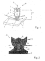
- tungsten inert gas welding is performed with an electrode 8 provided with a tip 11 of pure tungsten or alloyed tungsten and the arc 2 and the welding zone are protected by a sheath 6 of inert gas.
- the device 10 includes a current contact tube 7 supporting the rod-shaped tungsten electrode 8, which at the same time constitutes a clamping element for the tungsten electrode 8, and a protective gas nozzle 5 surrounding the current contact tube 7 and the tungsten electrode 8.
- the gap in the workpiece 1 is closed by means of a supplied welding filler 4 with a weld 3.
- the arc 2 is fed by a power source 9 during the welding process.
- Another device for welding under protective gas with a non-consumable electrode is in the document DE 32 07 537 A1 described, in which a cooled with cooling media electrode is provided, wherein in a conically shaped in the protective gas outlet opening Schutzgasdüse a conically shaped at its tip copper electrode is arranged, wherein the nozzle angle is smaller than the electrode angle formed and under the heating effect of the arc resulting weld pool is in a protective gas atmosphere formed by an active gas or inert gas.
- a problem is that the electrode is formed as a hollow electrode with internal cooling and cooling flow and thus difficult to replace with another electrode.
- An arc welding or cutting torch with a torch body and an electrode holder for a rod-shaped tungsten electrode received therein is disclosed DE 43 14 097 A1 described, in which between an outer body of the burner body and the electrode holder, a heat sink is provided, the material has a greater thermal conductivity than the material of the electrode holder and the outer body.
- the heat sink made of copper, the outer body of non-ferrous metal and the electrode holder made of stainless steel.
- the electrode is clamped in the burner head with a clamping sleeve, which is located in a clamping sleeve housing - a gas lens.
- the burner head can be water cooled.
- a further problem is that with this construction, intensive cooling of the electrode is not possible.
- a further problem is that the different materials which are close and largely connected to the electrode have different thermal conductivities, so that a continuous, continuous dissipation of the heat from the electrode into the burner head is hardly ensured.
- a higher energy density of electric arc is caused by a mechanical constriction of the arc during plasma welding with plasma welding torches, which in the publications DE 193 36 39 A and DE 39 30 267 A1 described reached.
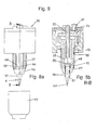
- a section through a plasma welding torch 21 which has a locked in an electrode holder and heat sink 12, rod-shaped tungsten electrode 13 with a conical tip 14, which is arranged in front of the output port 15 of a semi-oval, downwardly open plasma nozzle 16 - a copper nozzle - which constricts of the arc 20 is used.
- the plasma nozzle 16 in turn is surrounded by a downwardly open gas outlet opening 17 of a beam guide 18.
- the cone tip 14 of the tungsten electrode 13 is like the two openings 15,17 directed to the workpiece 19 to be machined.
- the arc 20 burns between the electrode 13 and the workpiece 19.
- the leakage of the electrons during arc welding is primarily due to thermal emission at the electrode tip 13. A sufficiently high number of escaping electrons is reached from a temperature of about 1700 K. ,
- the positioning of the electrode 13 to the plasma nozzle 16 has a significant effect on the process.
- the structure of the burner 21 is complicated due to the high accuracy requirements and the costs are approximately four to five times compared to the tungsten inert gas welding systems.
- a welding system based on the tungsten inert gas welding is in the document US 4,194,107 described, which also has a rod-shaped tungsten electrode, but which consists of several parts.
- the part directed towards the workpiece represents a pointed cone, to whose conical bottom a second part is soldered or welded in the form of a connecting cylinder.
- This is followed by the third part, a cylindrical connecting element, which is also soldered or welded to the connecting cylinder.
- the rod-shaped tungsten electrode is inserted into a cylindrical recess of a forceps-like holder head and supported by the holder head.
- Fig. 3 is schematically based on Fig. 1 an arc flow 22 from the electrode provided with negative potential 8 with the associated tip 11 to the positively charged workpiece 1 shown.
- the arc is an electric gas discharge and bound to freely movable charge carriers, to electrons and ions 23,24,25.
- the arc can be understood as a current-carrying conductor around which an annular magnetic field is formed.
- the dominant cause for the flow 22 in the free-burning arc 2 is the intrinsic magnetic compression due to the Lorentz force f L and the consequent high arc pressure in the constriction areas at the electrodes, which is compensated by an axial flow. This causes a strong convective heat flow and a high E-nergieeintrags prevail in the workpiece.
- the magnetic flux density B is proportional to the current density j and the current density j is inversely proportional behavior to the square of the diameter d, results in a very strong dependence of the self-magnetic compression of the diameter d of the arc 2 f L ⁇ 1 / d. 4 Since the current density j at the electrode tip 11 is very high, the plasma of the arc 2 is accelerated particularly strongly at this point.
- the gas 22 flowing through the pressure equalization must be heated to ionization temperature and cools the arc edge areas, which leads to the constriction of the arc 2, so that finally the flow 22 is formed.
- the leakage of electrons from the cathode is mainly due to thermal emission in tungsten inert gas welding.
- the number of escaping electrons increases with the cathode temperature.
- the isotherms therefore simultaneously represent iso-emission lines.
- each of the emission isotherms 26 represents the approach of the arc 2 with the diameter D H , wherein the approach of the arc 2 in conventional and normal cooling, which is discharged through the heat dissipation Q, located approximately in the center region of the apex 11.
- the invention has for its object to provide a tungsten inert gas welding torch whose burner head is designed so suitable that an increase in the energy density of the arc during tungsten inert gas welding can be achieved on the workpiece to be machined. Furthermore, a higher welding speed and a lower thermal influence of the material are to be achieved.
- an electrical connection for the operation of the tungsten electrode may be mounted.
- the suitable arrestable and replaceable electrode may even have a threaded bore adapted to the cylindrical part of the electrode body and be screwed directlydeigentitleiert in the threaded hole or having a passage having electrode holder, in which the electrode body is mounted fitted and adapted to the threaded hole an external thread for halternden Screwing into the threaded hole has.
- the passage having electrode holder may be a hollow screw.
- the electrode holder may be made of a material having a low thermal resistance, in particular copper or alloyed copper.
- the tungsten electrode body and the electrode holder are non-positively or cohesively connected to each other, wherein between the two a low electrical and thermal resistance is provided.
- the electrode cooling can be designed as liquid cooling.
- the tip end has a small distance a to the coolant-cooled heat sink.
- the opening angle ⁇ of the conical electrode tip can be between 7 ° and 90 °.
- the invention enables an increase in the energy density of the tungsten inert gas welding torch to be achieved.
- the emission isotherm shifts toward the free end of the electrode tip.
- the arc starts at a smaller diameter D N and thus has a higher energy density.
- the electrode diameter d e is above that customary in tungsten inert gas welding, the electrode angle ⁇ is between 7 ° and 90 °. Both are adjusted and adjusted for the respective application.
- the current density j of the arc is additionally amplified by the self-magnetic compression by means of the effective Lorentz force f L of the arc, which narrows the diameter d of the electric current lines, because the intrinsic magnetic compression is dependent on the diameter d of the arc.
- the diameter D N of the arc attachment becomes small enough, a self-contracting plasma jet and thus an increased energy density at the surface of the workpiece arise.
- the intensive cooling of the electrode tip is achieved in the invention in that the thermal resistance is minimized at the distance between the electrode tip and the cooling medium in the burner head.
- the cylindrical part of the tungsten electrode body may be formed in thermally more conductive metal, e.g. Embedded silver, copper, aluminum or metal alloys, and the conductive cross-section of the structural elements are increased.
- the invention makes it possible to increase the welding speed and the reduction of the path energy, the distortion and the thermal influence of the base material as well as the increase of the welding depth.
- the modified tungsten inert gas welding torch due to its construction, can be used for efficient welding, brazing, remelting and material properties of metallic materials.
- a tungsten inert gas torch with a non-consumable electrode is disclosed which does not achieve the high energy density through an additional nozzle, additional external gas inflow, or additional magnetic field.
- the tungsten inert gas welding torch has a simple structure.
- the conformable lockable electrode 8 may itself have a thread adapted to the threaded bore 43 on the cylindrical part of the tungsten electrode body 81 and be screwed directly into the threaded bore 43, or have a passage 45 having the electrode holder 44 in which the tungsten electrode body 81 fitted by means of soldering or pressing pressed is and has a threaded bore 43 adapted external thread for retaining screwing into the threaded hole 43 has.
- the tungsten electrode body 81 may be interchangeable either in the case of its own thread itself or, in the case of integration into the electrode holder 44 which can be actuated from outside the burner head 30, be exchangeable with the electrode holder 44.
- the electrode holder 44 having the passage 45 may be a hollow screw.
- the electrode holder 44 is made of a material with low thermal resistance, in particular copper, silver or their alloys.
- the cylindrical part of the tungsten electrode body 81 and the electrode holder 44 may be connected to one another in a force-fitting or cohesive manner, wherein a low electrical and thermal resistance is provided between the two.
- longitudinal channels 46 which may be present in the region on the outer wall 49 of the heat sink 37 and / or on the inner wall of the gas nozzle 47.
- the electrode cooling can be designed as liquid cooling.
- the flow line 33 is optionally introduced far into the elongated cavity 38 of the heat sink 37 in order to direct the inflowing, a low-temperature coolant directly into the tungsten electrode 8 near range.
- the return lines 34 terminate immediately behind the inner lid closure 40 and serve to drain the heated in the cavity 38 of the heat sink 37 coolant.
- the tip end 111 may preferably have a small distance a from the coolant-cooled heat sink 37.
- the opening angle ⁇ of the conical electrode tip 11 can be between 7 ° and 90 °.
- the emission isotherm 26 shifts toward the free tip end 111.
- the arc 2 starts at a smaller diameter D N , as in Fig. 5 shown, and thereby has a higher energy density.
- the electrode diameter d e is above the usual for tungsten inert gas welding diameter, the electrode angle ⁇ is between 7 ° to 90 ° and both are adapted and set for the appropriate application.
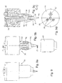
- FIG. 8 Several illustrations of another burner head 30 with a closed threaded bore 48 are shown within the heat sink 37, wherein in Fig. 8a an open burner head 30 with unscrewed gas nozzle 47 and the parallel to the burner head axis 42 guided longitudinal channels 46 in the region of the outer wall 49 of the heat sink 37 and in Fig. 8b a cross section along the line BB in Fig. 8a are shown without gas nozzle 47.
- the tungsten electrode body 81 introduced into the screwed-in electrode holder 44 contacts with its upper cylindrical end part the closed hood-shaped part 50 of the threaded bore 48, wherein the hood-shaped part 50 projects as part of the heat sink 37 into the coolant-flowed cavity 38.
- the process gas (inert gas) supply line 35 mounted in the cover closure 32 the inert gas flows in the flow direction 53 (arrow direction) through clearances and cavities of the burner head 30 and finally through the longitudinal channels 46 onto the workpiece.
- FIG. 9 Several illustrations of another burner head 30 with open threaded bore 51 to the coolant-flow-through cavity 38 of the heat sink 37 are shown, wherein Fig. 9a the closed burner head 30 in front view, Fig. 9b the open burner head 30 with unscrewed gas nozzle 47 and with the parallel to the burner head axis 42 guided longitudinal channels 46 on the heat sink 37, Fig. 9c a cross section along the line CC in Fig. 9b such as Fig. 9d a plan view of the lid closure 32 with the terminals 33,34 - a flow line 33 and two return lines 34 - for coolant and the gas supply 35 show.
- the torch head 30 may be associated with a hand-held tungsten inert gas torch or incorporated into an automated manufacturing / welding system assembly.
Abstract
Description
Die Erfindung betrifft einen Wolfram-Inertgas-Schweißbrenner mit einem Brennerkopf.The invention relates to a tungsten inert gas welding torch with a burner head.
Das Wolfram-Inertgasschweißen ist ein weit verbreitetes Verfahren. Die Schweißanlagen und vor allem die zugehörigen Schweißbrenner sind einfach aufgebaut, leicht zu warten und kostengünstig in der Anschaffung. Der Lichtbogen brennt frei zwischen einer nicht abschmelzenden Wolframelektrode und dem Werkstück, wobei die Energiedichte verhältnismäßig gering ist.Tungsten inert gas welding is a widely used process. The welding systems and especially the associated welding torches are simple, easy to maintain and inexpensive to buy. The arc burns freely between a non-consumable tungsten electrode and the workpiece, the energy density being relatively low.
Eine Vorrichtung zum Wolfram-Inertgasschweißen ist in der Druckschrift DIN ISO 857-1-2002-11 beschrieben, wobei, wie in
Eine andere Vorrichtung zum Schweißen unter Schutzgas mit einer nichtabschmelzenden Elektrode ist in der Druckschrift
Ein Problem besteht darin, dass die Elektrode als Hohlelektrode mit innerer Kühlung und Kühlströmung ausgebildet ist und damit schwerlich gegen eine andere Elektrode ausgetauscht werden kann.A problem is that the electrode is formed as a hollow electrode with internal cooling and cooling flow and thus difficult to replace with another electrode.
Ein Lichtbogenschweiß- oder -schneidbrenner mit einem Brennerkörper und einem darin aufgenommenen Elektrodenhalter für eine stabförmige Wolframelektrode ist in der Druckschrift
Ein Problem besteht darin, dass mit dieser Konstruktion eine intensive Kühlung der Elektrode nicht möglich ist.
Ein weiteres Problem besteht darin, dass die mit der Elektrode nahe und weitgehend in Verbindung stehenden, unterschiedlichen Materialien unterschiedliche Wärmeleitfähigkeiten aufweisen, so dass eine durchgehend kontinuierliche Ableitung der Wärme von der Elektrode aus in den Brennerkopf kaum gewährleistet ist.One problem is that with this construction, intensive cooling of the electrode is not possible.
A further problem is that the different materials which are close and largely connected to the electrode have different thermal conductivities, so that a continuous, continuous dissipation of the heat from the electrode into the burner head is hardly ensured.
Eine höhere Energiedichte von Lichtbogen wird durch eine mechanische Einschnürung des Lichtbogens beim Plasmaschweißen mit Plasmaschweißbrennern, die in den Druckschriften
Die Kegelspitze 14 der Wolframelektrode 13 ist wie die beiden Öffnungen 15,17 zum zu bearbeitenden Werkstück 19 gerichtet. Bei dem Plasmaschweißbrenner 21 brennt der Lichtbogen 20 zwischen der Elektrode 13 und dem Werkstück 19. Das Austreten der Elektronen beruht beim Lichtbogenschweißen hauptsächlich auf thermischer Emission an der Elektrodenspitze 13. Eine ausreichend hohe Anzahl von austretenden Elektronen wird ab einer Temperatur von ca. 1700 K erreicht.A higher energy density of electric arc is caused by a mechanical constriction of the arc during plasma welding with plasma welding torches, which in the publications
The
Ein Problem besteht darin, dass bei Plasmaschweißbrennern der Verschleiß der Plasmadüse 16 sehr hoch ist, da sie einen direkten Kontakt mit dem ca. 20000K heißen Plasmastrahl hat.One problem is that with plasma welding torches the wear of the
Auch die Positionierung der Elektrode 13 zur Plasmadüse 16 wirkt sich signifikant auf den Prozess aus. Der Aufbau der Brenner 21 ist aufgrund der hohen Genauigkeitsanforderungen kompliziert und die Kosten betragen im Vergleich zu den Wolfram-Inertgas-Schweißanlagen ca. das Vier- bis Fünffache.Also, the positioning of the
Ein anderes Bauprinzip wird in der Druckschrift
Ein Problem besteht darin, dass in dem System, das auf der Einschnürung des Lichtbogens mittels äußerer Gasanströmung beruht, der Spalt zwischen der E-Iektrode und der Einschnürungsgasdüse sehr klein gehalten werden muss. Das ist nur mit sehr kleinen Fertigungstoleranzen zu erreichen. Deshalb erfordern die entsprechenden Brenner ebenfalls einen sehr hohen Fertigungsaufwand und sehr hohe Herstellungskosten.One problem is that in the system based on the arc constriction by external gas inflow, the gap between the electrode and the constricting gas nozzle must be kept very small. This can only be achieved with very small manufacturing tolerances. Therefore, the corresponding burner also require a very high production cost and very high production costs.
Des Weiteren ist die magnetische Einschnürung des Lichtbogens in der Druckschrift
Ein Problem besteht darin, dass bei Beeinflussung des Lichtbogens durch Magnetfelder die zugehörigen Spulen in Lichtbogennähe positioniert werden müssen. Das beeinflusst die Zugänglichkeit und erfordert temperatur- und strahlungsresistente Bauelemente.One problem is that when the arc is affected by magnetic fields, the associated coils must be positioned near the arc. This affects accessibility and requires temperature and radiation resistant components.
Eine Schweißanlage auf der Basis des Wolfram-Inertgasschweißens ist in der Druckschrift
In
Der Lichtbogen ist eine elektrischen Gasentladung und an frei bewegliche Ladungsträger, an Elektronen und Ionen 23,24,25, gebunden. Der Lichtbogen kann als stromdurchflossener Leiter aufgefasst werden, um den sich ein ringförmiges Magnetfeld ausbildet. Die dominierende Ursache für die Strömung 22 im frei brennenden Lichtbogen 2 ist die eigenmagnetische Kompression infolge der Lorentzkraft fL und der daraus folgende hohe Lichtbogendruck in den Einschnürungsgebieten an den Elektroden, der durch eine axiale Strömung ausgeglichen wird. Dabei wird ein starker konvektiver Wärmestrom und eine hohe E-nergieeintragsdichte in das Werkstück verursacht.The arc is an electric gas discharge and bound to freely movable charge carriers, to electrons and
Da sich die magnetische Flussdichte B proportional zur Stromdichte j und die Stromdichte j umgekehrt proportional zum Quadrat des Durchmessers d verhalten, ergibt sich eine sehr starke Abhängigkeit der eigenmagnetischen Kompression vom Durchmesser d des Lichtbogens 2 mit fL ~ 1/d4. Da die Stromdichte j an der Elektrodenspitze 11 sehr hoch ist, wird das Plasma des Lichtbogens 2 an dieser Stelle besonders stark beschleunigt. Das durch den Druckausgleich nachströmende Gas 22 muss auf lonisationstemperatur aufgeheizt werden und kühlt die Lichtbogenrandbereiche aus, was zur Einschnürung des Lichtbogens 2 führt, so dass sich final die Strömung 22 ausbildet.Since the magnetic flux density B is proportional to the current density j and the current density j is inversely proportional behavior to the square of the diameter d, results in a very strong dependence of the self-magnetic compression of the diameter d of the arc 2 f L ~ 1 / d. 4 Since the current density j at the
Das Austreten der Elektronen aus der Kathode beruht beim Wolfram-Inertgasschweißen hauptsächlich auf thermischer Emission. Die Anzahl der austretenden Elektronen steigt mit der Kathodentemperatur. Die Isothermen stellen daher gleichzeitig lsoemissionslinien dar.The leakage of electrons from the cathode is mainly due to thermal emission in tungsten inert gas welding. The number of escaping electrons increases with the cathode temperature. The isotherms therefore simultaneously represent iso-emission lines.
Bei gemeinsamer Betrachtung der
Ein Problem besteht darin, dass schon der relativ große Durchmesser DH des Lichtbogenansatzes 26 auf der Elektrodenspitze 11 einen größeren Durchmesser d des Lichtbogens 2 in Richtung zum Werkstück 1 und insbesondere auf der Oberfläche des Werkstücks 1 erzeugt, wodurch schließlich eine geringe Stromdichte j und damit geringe Energiedichte auf dem Werkstück 1 vorhanden sind.One problem is that even the relatively large diameter D H of the
Der Erfindung liegt die Aufgabe zugrunde, einen Wolfram-Inertgas-Schweißbrenner anzugeben, dessen Brennerkopf derart geeignet ausgebildet ist, dass eine Erhöhung der Energiedichte des Lichtbogens beim Wolfram-Inertgasschweißen auf dem zu bearbeitenden Werkstück erzielt werden kann. Es sollen des Weiteren auch eine höhere Schweißgeschwindigkeit und eine geringere thermische Beeinflussung des Werkstoffs erreicht werden.The invention has for its object to provide a tungsten inert gas welding torch whose burner head is designed so suitable that an increase in the energy density of the arc during tungsten inert gas welding can be achieved on the workpiece to be machined. Furthermore, a higher welding speed and a lower thermal influence of the material are to be achieved.
Die Aufgabe wird durch die Merkmale des Patentanspruchs 1 gelöst.
Der Wolfram-Inertgas-Schweißbrenner ist mit einem Brennerkopf versehen, der gemäß dem Patentanspruch 1 aus
- einem Gehäusezylinder mit einem oberen Deckelverschluss, durch den zumindest eine Vorlaufleitung und eine Rücklaufleitung für Kühlmittel sowie eine Inertgaszuleitung und ein Elektroanschluss für den Betrieb einer Wolframelektrode geführt sind,
- einem innerhalb des Gehäusezylinders befindlichen länglichen Kühlkörper mit einem darin befindlichen länglichen, an der oberen Stirnseite des Kühlkörpers offenen Hohlraum und einem darauf befindlichen Innendeckelverschluss, durch den die Leitungen für das Kühlmittel führen,
- einer auf der unteren Stirnseite des Kühlkörpers längs der Brennerkopfachse eingelassene Gewindebohrung,
- einer in die Gewindebohrung passfähige arretierfähige Elektrode, die einen zylindrischen und mit einer Kegelspitze versehenen Wolframelektrodenkörper aufweist, dessen Spitzenende in einem vorgegebenen Abstand a zur unteren Stirnseite des Kühlkörpers angeordnet ist, und
- einer mit dem länglichen Kühlkörper unter Einbindung von Längskanälen in Verbindung stehende verschraubbare Gasdüse, die den Kühlkörper und die Elektrode umgibt,
wobei der thermische Widerstand der dem Wolframelektrodenkörper nachgeordneten Materialien niedrig ist und die Kühlung über den Kühlkörper bis an die Gewindebohrung oder direkt an die Elektrode herangeführt ist und sich eine Emissionsisotherme ausbildet, die durch die intensive Kühlung der Elektrode, den Elektrodendurchmesser de und durch einen definierten Winkel α in Richtung zum freien Spitzenende des Wolframelektrodenkörpers verschoben ist.The object is solved by the features of patent claim 1.
The tungsten inert gas welding torch is provided with a burner head, according to the patent claim 1 of
- a housing cylinder with an upper cover closure through which at least one supply line and a return line for coolant as well as an inert gas supply line and an electrical connection for the operation of a tungsten electrode are guided,
- an elongated heat sink located within the housing cylinder with an elongated cavity located therein at the upper end face of the heat sink and an inner lid closure thereon through which the lines for the coolant pass;
- one on the lower end side of the heat sink along the Brennerkopfachse recessed threaded hole,
- a lockable in the threaded hole lockable electrode having a cylindrical and provided with a conical tip Wolframelektrodenkörper whose tip end is arranged at a predetermined distance a to the lower end face of the heat sink, and
- a screwable gas nozzle, which surrounds the heat sink and the electrode, connected to the elongated heat sink with the involvement of longitudinal channels,
wherein the thermal resistance of the tungsten electrode body downstream materials is low and the cooling is brought via the heat sink to the threaded hole or directly to the electrode and an emission isotherm is formed by the intensive cooling of the electrode, the electrode diameter d e and by a defined Angle α is shifted toward the free tip end of the tungsten electrode body.
Nahe oder außerhalb des Brennerkopfes an der Rücklaufleitung kann ein Elektroanschluss für den Betrieb der Wolframelektrode angebracht sein.Near or outside the burner head on the return line, an electrical connection for the operation of the tungsten electrode may be mounted.
Die passfähige arretierbare und austauschbare Elektrode kann selbst am zylindrischen Teil des Elektrodenkörpers ein der Gewindebohrung angepasstes Gewinde aufweisen und direkt kühlkörperkontaktiert in die Gewindebohrung eingeschraubt sein oder einen Durchgang aufweisende Elektrodenhalterung haben, in der der Elektrodenkörper eingepasst befestigt ist und die ein der Gewindebohrung angepasstes Außengewinde zum halternden Einschrauben in die Gewindebohrung besitzt.The suitable arrestable and replaceable electrode may even have a threaded bore adapted to the cylindrical part of the electrode body and be screwed directly Kühlkörperkontaktiert in the threaded hole or having a passage having electrode holder, in which the electrode body is mounted fitted and adapted to the threaded hole an external thread for halternden Screwing into the threaded hole has.
Die den Durchgang aufweisende Elektrodenhalterung kann eine Hohlschraube sein.The passage having electrode holder may be a hollow screw.
Die Elektrodenhalterung kann aus einem Material mit niedrigem thermischem Widerstand, insbesondere aus Kupfer oder legiertem Kupfer bestehen.The electrode holder may be made of a material having a low thermal resistance, in particular copper or alloyed copper.
Der Wolframelektrodenkörper und die Elektrodenhalterung sind kraft- oder stoffschlüssig miteinander verbunden, wobei zwischen beiden ein geringer elektrischer und thermischer Widerstand vorgesehen ist.The tungsten electrode body and the electrode holder are non-positively or cohesively connected to each other, wherein between the two a low electrical and thermal resistance is provided.
Zwischen dem länglichen Kühlkörper und der Gasdüse sind parallel zur Brennerkopfachse gerichtete Längskanäle vorhanden, die an der Außenwandung des Kühlkörpers und/oder an der Innenwandung der Gasdüse eingebracht sind.Between the elongated heat sink and the gas nozzle longitudinal channels are provided parallel to the burner head axis, which are introduced on the outer wall of the heat sink and / or on the inner wall of the gas nozzle.
Die Elektrodenkühlung kann als Flüssigkeitskühlung ausgebildet sein.The electrode cooling can be designed as liquid cooling.
Das Spitzenende weist einen geringen Abstand a zum kühlmittelgekühlten Kühlkörper auf.The tip end has a small distance a to the coolant-cooled heat sink.
Der öffnende Winkel α der kegelförmigen Elektrodenspitze kann zwischen 7° und 90° liegen.The opening angle α of the conical electrode tip can be between 7 ° and 90 °.
Die Erfindung ermöglicht es, dass eine Erhöhung der Energiedichte des Wolfram-Inertgas-Schweißbrenners erreicht wird.The invention enables an increase in the energy density of the tungsten inert gas welding torch to be achieved.
Durch eine intensive Kühlung und bei bestimmten Winkeln der kegelförmigen Elektrode verschiebt sich die Emissionsisotherme in Richtung zum freien Ende der Elektrodenspitze. Damit setzt der Lichtbogen an einem kleineren Durchmesser DN an und weist dadurch eine höhere Energiedichte auf. Der Elektrodendurchmesser de liegt über den beim Wolfram-Inertgasschweißen üblichen, der Elektrodenwinkel α liegt zwischen 7° bis 90°. Beide werden für die entsprechende Anwendung angepasst und eingestellt.By intensive cooling and at certain angles of the conical electrode, the emission isotherm shifts toward the free end of the electrode tip. Thus, the arc starts at a smaller diameter D N and thus has a higher energy density. The electrode diameter d e is above that customary in tungsten inert gas welding, the electrode angle α is between 7 ° and 90 °. Both are adjusted and adjusted for the respective application.
Die Stromdichte j des Lichtbogens wird zusätzlich durch die eigenmagnetische Kompression mittels der wirkenden Lorentzkraft fL des Lichtbogens verstärkt, die den Durchmesser d der elektrischen Stromlinien verengt, weil die eigenmagnetische Kompression abhängig vom Durchmesser d des Lichtbogens ist. Wenn der Durchmesser DN des Lichtbogenansatzes klein genug wird, entstehen ein sich selbst kontrahierender Plasmastrahl und damit eine erhöhte Energiedichte an der Oberfläche des Werkstücks.The current density j of the arc is additionally amplified by the self-magnetic compression by means of the effective Lorentz force f L of the arc, which narrows the diameter d of the electric current lines, because the intrinsic magnetic compression is dependent on the diameter d of the arc. When the diameter D N of the arc attachment becomes small enough, a self-contracting plasma jet and thus an increased energy density at the surface of the workpiece arise.
Die intensive Kühlung der Elektrodenspitze wird in der Erfindung dadurch gelöst, dass auf der Distanz zwischen der Elektrodenspitze und dem Kühlmedium im Brennerkopf der thermische Widerstand möglichst gering ist.The intensive cooling of the electrode tip is achieved in the invention in that the thermal resistance is minimized at the distance between the electrode tip and the cooling medium in the burner head.
Der gesamte thermische Widerstand ergibt sich aus den Summen der einzelnen Stoff- bzw. Kontaktwiderständen, die es zu minimieren gilt. Dazu kann der zylindrische Teil des Wolframelektrodenkörpers in thermisch besser leitfähigen Metall, z.B. Silber, Kupfer, Aluminium oder Metalllegierungen, eingebettet werden und der leitende Querschnitt der Konstruktionselemente vergrößert werden.The total thermal resistance results from the sums of the individual material or contact resistances, which must be minimized. For this, the cylindrical part of the tungsten electrode body may be formed in thermally more conductive metal, e.g. Embedded silver, copper, aluminum or metal alloys, and the conductive cross-section of the structural elements are increased.
Die Erfindung ermöglicht die Erhöhung der Schweißgeschwindigkeit und das Verringerung der Streckenenergie, des Verzuges sowie der thermischen Beeinflussung des Grundwerkstoffes als auch die Erhöhung der Einschweißtiefe. Der modifizierte Wolfram-Inertgas-Schweißbrenner kann aufgrund seiner Konstruktion zum effizienten Schweißen, Löten, Umschmelzen und Stoffeigenschaftsändern metallischer Werkstoffe genutzt werden.The invention makes it possible to increase the welding speed and the reduction of the path energy, the distortion and the thermal influence of the base material as well as the increase of the welding depth. The modified tungsten inert gas welding torch, due to its construction, can be used for efficient welding, brazing, remelting and material properties of metallic materials.
Es wird ein Wolfram-Inertgas-Schweißbrenner mit einer nicht abschmelzenden Elektrode angegeben, der die hohe Energiedichte nicht durch eine zusätzliche Düse, eine zusätzliche äußere Gasanströmung oder ein zusätzliches Magnetfeld erreicht.A tungsten inert gas torch with a non-consumable electrode is disclosed which does not achieve the high energy density through an additional nozzle, additional external gas inflow, or additional magnetic field.
Dazu weist der Wolfram-Inertgas-Schweißbrenner einen einfachen Aufbau auf.For this purpose, the tungsten inert gas welding torch has a simple structure.
Die Erfindung wird anhand mehrerer Ausführungsbeispiele mittels mehrerer Zeichnungen näher erläutert:
Es zeigen:
- Fig. 1
- eine schematische Darstellung einer Anordnung zum Wolfram-Inertgasschweißen nach dem Stand der Technik,
- Fig. 2
- eine schematische Darstellung eines Endteils des Brennerkopfes eines Plasmaschweißbrenners nach dem Stand der Technik,
- Fig. 3
- eine schematische Darstellung eines Lichtbogens,
- Fig. 4
- eine Isothermen-Darstellung des Lichtbogenansatzes an einer kegelförmigen Wolframelektrode mit einer Elektrodenspitze mit geringer Kühlung nach dem Stand der Technik,
- Fig. 5
- eine Isothermen-Darstellung des Lichtbogenansatzes an eine kegelförmigen Wolframelektrode mit einer Elektrodenspitze mit intensiver Kühlung gemäß dem erfindungsgemäßen Brennerkopfes,
- Fig. 6
- eine Seitenansicht des erfindungsgemäßen Wolfram-Inertgas- Schweißbrennerkopfes,
- Fig. 7
- eine Schnittdarstellung des erfindungsgemäßen Wolfram-Inertgas- Schweißbrennerkopfes nach
Fig. 6 , - Fig. 8
- mehrere Darstellungen eines Brennerkopfes mit geschlossener Gewindebohrung im Kühlkörper, wobei
Fig. 8a einen geöffneten Brennerkopf mit abgeschraubter Gasdüse und den parallel zu der Brennerkopfachse geführten Längskanälen am Kühlkörper und
Fig. 8b einen Querschnitt längs der Linie B-B inFig. 8a zeigen, und - Fig. 9
- mehrere Darstellungen eines Brennerkopfes mit offener Gewindebohrung zum kühlmitteldurchströmten Hohlraum des Kühlkörpers, wobei
Fig. 9a den geschlossenen Brennerkopf in Vorderansicht,
Fig. 9b den geöffneten Brennerkopf mit abgeschraubter Gasdüse und den parallel zur Brennerkopfachse geführten Längskanälen am Kühlkörper,
Fig. 9c einen Querschnitt längs der Linie C-C inFig. 9b und Fig. 9d eine Draufsicht auf den Deckelverschluss mit den Anschlüssen für Kühlmittel und Gas
Show it:
- Fig. 1
- a schematic representation of an arrangement for tungsten inert gas welding according to the prior art,
- Fig. 2
- a schematic representation of an end portion of the burner head of a plasma welding torch according to the prior art,
- Fig. 3
- a schematic representation of an arc,
- Fig. 4
- an isothermal representation of the arc approach to a conical tungsten electrode with a low-cooling electrode tip according to the prior art,
- Fig. 5
- an isothermal representation of the arc approach to a conical tungsten electrode with an electrode tip with intensive cooling according to the burner head according to the invention,
- Fig. 6
- a side view of the tungsten inert gas welding torch head according to the invention,
- Fig. 7
- a sectional view of the tungsten inert gas welding torch head according to the invention
Fig. 6 . - Fig. 8
- several representations of a burner head with a closed threaded bore in the heat sink, wherein
Fig. 8a an open burner head with unscrewed gas nozzle and the guided parallel to the burner head axis longitudinal channels on the heat sink and
Fig. 8b a cross section along the line BB inFig. 8a show, and - Fig. 9
- several representations of a burner head with an open threaded bore to the coolant-flowed cavity of the heat sink, wherein
Fig. 9a the closed burner head in front view,
Fig. 9b the open burner head with screwed-off gas nozzle and the parallel to the burner head axis guided longitudinal channels on the heat sink,
Fig. 9c a cross section along the line CC inFig. 9b and Fig. 9d a plan view of the lid closure with the connections for coolant and gas
Im Folgenden werden die
Der darin dargestellte Brennerkopf 30 eines Wolfram-Inertgas-Schweißbrenners besteht aus
einem Gehäusezylinder 31 mit einem oberen Deckelverschluss 32, durchden eine Vorlaufleitung 33 und zwei Rücklaufleitungen 34 für Kühlmittel sowie eine Inertgaszuleitung 35und ein Elektroanschluss 36 für denBetrieb einer Wolframelektrode 8 geführt sind,- einem innerhalb des Gehäusezylinders 31 befindlichen länglichen Kühlkörper 37 mit parallel zur
Brennerkopfachse 42 gerichteten Längskanälen 46 und mit einem darin befindlichen länglichen, an der oberen Stirnseite 39 desKühlkörpers 37 offenen Hohlraum 38 und einem darauf befindlichen Innendeckelverschluss 40, durch den dieLeitungen - einer auf der unteren Stirnseite 41 des
Kühlkörpers 37 längs der Brennerkopfachse 42eingelassene Gewindebohrung 43, - einer in
die Gewindebohrung 43 passfähige arretierfähige Elektrodenhalterung 44 mit einem inneren zylindrischen Durchgang 45, - einer
mit dem Gehäusezylinder 31 in Verbindung stehende verschraubbare Gasdüse 47, dieden Kühlkörper 37 und dieElektrodenhalterung 44 umgibt, - einem in den inneren zylindrischen Durchgang 45 eingebrachten zylindrischen und mit einer
Kegelspitze 11 versehenen Wolframelektrodenkörper 81 mit dem Durchmesser de,dessen Spitzenende 111 in einem vorgegebenen Abstand a zur unteren Stirnseite 41 desKühlkörpers 37 angeordnet ist,
The
- a
housing cylinder 31 with anupper cover closure 32, through which afeed line 33 and tworeturn lines 34 for coolant and an inertgas feed line 35 and anelectrical connection 36 for the operation of atungsten electrode 8 are guided, - an
elongated heat sink 37 located inside thehousing cylinder 31 withlongitudinal channels 46 directed parallel to theburner head axis 42 and with anelongate cavity 38 open on the upper end face 39 of theheat sink 37 and aninner cover closure 40 thereon, through which thelines - a on the
lower end 41 of theheat sink 37 along theBrennerkopfachse 42 recessed threadedhole 43, - a
lockable electrode holder 44 with an innercylindrical passage 45 which can be passed into the threaded bore 43, - a
screwable gas nozzle 47 communicating with thehousing cylinder 31 and surrounding theheat sink 37 and theelectrode support 44, - a cylindrical
tungsten electrode body 81 having a diameter d e and provided with acone tip 11 in the innercylindrical passage 45, thetip end 111 of which is arranged at a predetermined distance a from thelower end face 41 of theheat sink 37;
Außerhalb des Brennerkopfes 30 kann an der Rücklaufleitung 34 ein Elektroanschluss 36 für den Betrieb der Wolframelektrode 8 angebracht sein.Outside the
Die passfähige arretierbare Elektrode 8 kann selbst am zylindrischen Teil des Wolframelektrodenkörpers 81 ein der Gewindebohrung 43 angepasstes Gewinde aufweisen und direkt kühlkörperkontaktiert in die Gewindebohrung 43 eingeschraubt sein oder eine den Durchgang 45 aufweisende Elektrodenhalterung 44 haben, in der der Wolframelektrodenkörper 81 mittels Löten oder Einpressen eingepasst befestigt ist und die ein der Gewindebohrung 43 angepasstes Außengewinde zum halternden Einschrauben in die Gewindebohrung 43 besitzt.The conformable
Der Wolframelektrodenkörper 81 kann entweder im Falle eines eigenen Gewindes selbst austauschbar oder im Falle der Einbindung in die von außerhalb des Brennerkopfes 30 betätigbare Elektrodenhalterung 44 mit der Elektrodenhalterung 44 gemeinsam austauschbar sein.The
Die den Durchgang 45 aufweisende Elektrodenhalterung 44 kann eine Hohlschraube sein.The
Die Elektrodenhalterung 44 besteht aus einem Material mit niedrigem thermischem Widerstand, insbesondere aus Kupfer, Silber oder deren Legierungen.The
Der zylindrische Teil des Wolframelektrodenkörpers 81 und die Elektrodenhalterung 44 können kraft- oder stoffschlüssig miteinander verbunden sein, wobei zwischen beiden ein geringer elektrischer und thermischer Widerstand vorgesehen ist.The cylindrical part of the
Zwischen dem länglichen Kühlkörper 37 und der Gasdüse 47 können in axialer Richtung zur Brennerkopfachse 42 gerichtete Längskanäle 46 vorhanden sein, die im Bereich an der Außenwandung 49 des Kühlkörpers 37 und/oder auch an der Innenwandung der Gasdüse 47 vorhanden sein können.Between the
Die Elektrodenkühlung kann als Flüssigkeitskühlung ausgebildet sein. Dabei ist die Vorlaufleitung 33 wahlweise bis weit in den länglichen Hohlraum 38 des Kühlkörpers 37 hinein eingebracht, um das einströmende, eine Niedrigtemperatur aufweisende Kühlmittel direkt in den der Wolframelektrode 8 nahen Bereich zu leiten. Die Rücklaufleitungen 34 enden unmittelbar hinter dem Innendeckelverschluss 40 und dienen zum Abströmen des im Hohlraum 38 des Kühlkörpers 37 erwärmten Kühlmittels.The electrode cooling can be designed as liquid cooling. In this case, the
Das Spitzenende 111 kann vorzugsweise einen geringen Abstand a zum kühlmittelgekühlten Kühlkörper 37 aufweisen.The
Der öffnende Winkel α der kegelförmigen Elektrodenspitze 11 kann zwischen 7° und 90° liegen.
Während des Erzeugens des Lichtbogens und danach strömt das Prozessgas über die Prozessgaszuleitung 35 durch den unter dem Deckelverschluss 32 befindlichen Freiraum 29 über die Längskanäle 46 schließlich an der kegelförmigen Wolframelektrodenspitze 11 vorbei in Richtung auf das zu bearbeitende Werkstück 1.The opening angle α of the
During the generation of the arc and then the process gas flows through the process
Durch eine intensive Kühlung und bei bestimmten Winkeln α der kegelförmigen Elektrode 8 verschiebt sich die Emissionsisotherme 26 in Richtung zum freien Spitzenende 111. Damit setzt der Lichtbogen 2 an einem kleineren Durchmesser DN an, wie in
In den folgenden
In
Der in die eingeschraubte Elektrodenhalterung 44 eingebrachte Wolframelektrodenkörper 81 kontaktiert mit seinem oberen zylindrischen Endteil den geschlossenen haubenförmigen Teil 50 der Gewindebohrung 48, wobei der haubenförmige Teil 50 als Teil des Kühlkörpers 37 in den kühlmitteldurchströmten Hohlraum 38 hineinragt.
Von der im Deckelverschluss 32 montierten Prozessgas(Inertgas)zuleitung 35 aus strömt das Inertgas in Strömungsrichtung 53 (Pfeilrichtung) durch Frei- und Hohlräume des Brennerkopfes 30 sowie schließlich durch die Längskanäle 46 auf das Werkstück.In
The
From the process gas (inert gas)
In
In den beiden letzten Fällen gemäß
In the last two cases according to
Damit kann Folgendes zusammengefasst werden:
- Es liegt ein Wolfram-Inertgas-Schweißbrenner
mit einem Brennerkopf 30 zum Wolfram-Inertgasschweißen mit nicht abschmelzender Elektrode 8 vor, bei dem hohe Energiedichten oder Stromdichten j durch eine intensive Kühlung der Elektrode 8 erreicht werden kann. Wie inFig. 5 gezeigt ist, verschiebt sich fürden erfindungsgemäßen Brennerkopf 30 dieEmissionsisotherme 261 in Richtungzum freien Spitzenende 111, wobei sich der Durchmesser DN des Lichtbogenansatzes wesentlich verringert.Die Elektrode 8 des Wolfram-Inertgas-Schweißbrenners kann als Katode betrieben werden. Das Spitzenende 111 der Katode weist einen möglichst kleinen Abstand a zur unteren Stirnseite 41 des wassergekühlten Kühlkörper 37 auf.Die Wolframelektrode 8 ist mit einem gut leitenden Metall oder direkt mit dem Kühlmittel verbunden, um eine intensive Kühlung zu ermöglichen.
- There is a tungsten inert gas welding torch with a
burner head 30 for tungsten inert gas welding withnon-consumable electrode 8, in which high energy densities or current densities j can be achieved by intensive cooling of theelectrode 8. As inFig. 5 is shown, shifts for theburner head 30 according to the invention, theemission isotherm 261 toward thefree tip end 111, wherein the diameter D N of the arc approach significantly reduced. Theelectrode 8 of the tungsten inert gas welding torch can be operated as a cathode. - The
tip end 111 of the cathode has the smallest possible distance a to thelower end face 41 of the water-cooledheat sink 37. - The
tungsten electrode 8 is connected to a highly conductive metal or directly to the coolant to allow for intensive cooling.
Damit ergeben sich wesentliche Vorteile der Erfindung:
- Durch die intensive Kühlung der Wolframelektrode 8 wird die Energiedichte oder die Stromdichte j des Lichtbogens erhöht. Dadurch wird die notwendige Streckenenergie zum Fügen des Werkstücks 1 verringert bzw. die Schweißgeschwindigkeit erhöht.
- Der mittels der betätigbaren Elektrodenhalterung 44
austauschbare Wolframelektrodenkörper 81 hat einen definierten Abstand a zwischen seinem Spitzenende 111und dem Kühlkörper 37. Das vereinfacht den Elektrodenwechsel und erspart nachträgliche Justagearbeiten. Der Elektrodenwechsel kann automatisiert durchgeführt werden. - Durch die intensive Kühlung der Elektrode 8 wird der Verschleiß vermindert.
Wird die Wolframelektrode 8 als Anode genutzt, z.B. beim Schweißen von Aluminium, ist zwar die Strombelastbarkeit wegen der intensiven Kühlung höher, aber es kann gleichermaßen die Energiedichte erhöht werden.
- Due to the intensive cooling of the
tungsten electrode 8, the energy density or the current density j of the arc is increased. As a result, the necessary path energy for joining the workpiece 1 is reduced or the welding speed is increased. - The exchangeable by means of the
actuatable electrode holder 44tungsten electrode body 81 has a defined distance a between itstip end 111 and theheat sink 37. This simplifies the electrode replacement and saves subsequent adjustment work. The electrode change can be carried out automatically. - Due to the intensive cooling of the
electrode 8, the wear is reduced. - If the
tungsten electrode 8 is used as an anode, for example when welding aluminum, the current carrying capacity is higher because of the intensive cooling, but it is equally possible to increase the energy density.
Der Brennerkopf 30 kann zu einem mit einem Handgriff versehenen Wolfram-Inertgas-Schweißbrenner gehören oder in eine Anordnung eines automatischen Fertigungs-/Schweißsystem eingebracht sein.The
- 11
- Werkstückworkpiece
- 22
- LichtbogenElectric arc
- 33
- SchweißnahtWeld
- 44
- Schweißzusatzfiller
- 55
- SchutzgasdüseShield Cup
- 66
- Gasmantelgas jacket
- 77
- StromkontaktrohrCurrent contact tube
- 88th
- Wolframelektrodetungsten electrode
- 8181
- WolframelektrodenkörperTungsten electrode body
- 99
- Energiequelleenergy
- 1010
- Vorrichtung nach dem Stand der TechnikDevice according to the prior art
- 1111
- Kegelspitzeapex
- 111111
- Spitzenendesharp end
- 1212
- Kühlkörperheatsink
- 1313
- Wolframelektrodetungsten electrode
- 1414
- Elektrodenspitzeelectrode tip
- 1515
- Düsenöffnungnozzle opening
- 1616
- Plasmadüseplasma nozzle
- 1717
- GasaustrittsöffnungGas outlet
- 1818
- Strahlführungbeamline
- 1919
- Werkstückworkpiece
- 2020
- LichtbogenElectric arc
- 2121
- PlasmaschweißbrennerPlasma Welding Torches
- 2222
- LichtbogenströmungArc flow
- 2323
- Erster LadungsträgerFirst charge carrier
- 2424
- Zweiter LadungsträgerSecond charge carrier
- 2525
- Dritter LadungsträgerThird load carrier
- 2626
- EmissionsisothermeEmissionsisotherme
- 2727
- Magnetische FeldlinienMagnetic field lines
- 2828
- Elektrische StrömungslinienElectric flow lines
- 2929
- Freiraumfree space
- 3030
- Brennerkopfburner head
- 3131
- Gehäusezylinderhousing cylinder
- 3232
- Deckelverschlusslid closure
- 3333
- Vorlaufleitungsupply line
- 3434
- RücklaufleitungReturn line
- 3535
- ProzessgaszuleitungProcess gas feed
- 3636
- Elektrischer AnschlussElectrical connection
- 3737
- Kühlkörperheatsink
- 3838
- Hohlraumcavity
- 3939
- Obere StirnseiteUpper front side
- 4040
- InnendeckelverschlussInner lid closure
- 4141
- Untere StirnseiteLower front side
- 4242
- BrennerkopfachseBurner head axis
- 4343
- Gewindebohrungthreaded hole
- 4444
- Elektrodenhalterungelectrode holder
- 4545
- Durchgangpassage
- 4646
- Längskanälelongitudinal channels
- 4747
- Gasdüsegas nozzle
- 4848
- Geschlossene GewindebohrungClosed threaded hole
- 4949
- Außenwandungouter wall
- 5050
- Haubenförmiger TeilHood-shaped part
- 5151
- Offene GewindebohrungOpen threaded hole
- 5252
- Kontaktstellecontact point
- 5353
- ProzessgasströmungsrichtungProcess gas flow direction
- aa
- Abstanddistance
- αα
- Winkelangle
- dd
- Durchmesser des LichtbogensDiameter of the arc
- de d e
- ElektrodendurchmesserElectrode diameter
- fL f L
- LorentzkraftLorentz force
- DH D H
- Durchmesserdiameter
- DN D N
- Durchmesserdiameter
- BB
- Flussdichteflux density
- jj
- Stromdichtecurrent density
Claims (12)
dadurch gekennzeichnet,
dass nahe oder außerhalb des Brennerkopfes (30) vorzugsweise an der Rücklaufleitung (34) ein Elektroanschluss (36) für den Betrieb der Wolframelektrode (8) angebracht ist.Tungsten inert gas welding torch according to claim 1,
characterized,
that an electrical connection (36) for the operation of the tungsten electrode (8) is preferably mounted on or near the burner head (30) on the return line (34).
dadurch gekennzeichnet,
dass die passfähige arretierbare Elektrode (8) selbst am zylindrischen Teil des Wolframelektrodenkörpers (81) ein der Gewindebohrung (43) angepasstes Gewinde aufweist und direkt kühlkörperkontaktiert in die Gewindebohrung (43) eingeschraubt ist.Tungsten inert gas welding torch according to claim 1,
characterized,
that the matching capable lockable electrode (8) comprises a matched the threaded bore (43) threaded itself on the cylindrical part of the tungsten electrode body (81) and heat sink directly contacted into the threaded bore (43) is screwed.
dadurch gekennzeichnet,
dass die passfähige arretierbare Elektrode (8) einen Durchgang (45) aufweisende Elektrodenhalterung (44) hat, in den der Wolframelektrodenkörper (81) mittels Löten oder Einpressen eingepasst befestigt ist, wobei die Elektrodenhalterung (44) ein der Gewindebohrung (43) angepasstes Außengewinde zum halternden Einschrauben in die Gewindebohrung (43) besitzt.Tungsten inert gas welding torch according to claim 1,
characterized,
that the matching capable lockable electrode (8) has a passage (45) having electrode holder (44) is fixed in which the tungsten electrode body (81) fitted by means of soldering or pressing in, wherein the electrode holder (44) of the threaded bore (43) adapted external thread for has retaining screwing into the threaded hole (43).
dadurch gekennzeichnet,
dass die den Durchgang (45) aufweisende Elektrodenhalterung (44) als eine Hohlschraube ausgebildet ist.Tungsten inert gas welding torch according to claim 4,
characterized,
the electrode holder (44) having the passage (45) is designed as a hollow screw.
dadurch gekennzeichnet,
dass der Wolframelektrodenkörper (81) entweder im Falle eines eigenen Gewindes selbst austauschbar oder im Falle der Einbindung in die von außerhalb des Brennerkopfes (30) betätigbare Elektrodenhalterung (44) mit der Elektrodenhalterung (44) gemeinsam austauschbar ist.Tungsten inert gas welding torch according to claim 3 or 4, 5,
characterized,
in that the tungsten electrode body (81) is exchangeable either in the case of its own thread itself or, in the case of integration into the electrode holder (44) which can be actuated from outside the burner head (30), is exchangeable with the electrode holder (44).
dadurch gekennzeichnet,
dass die Elektrodenhalterung (44) aus einem Material mit niedrigem thermischem Widerstand, insbesondere aus Kupfer, Silber und deren Legierungen besteht.Tungsten inert gas welding torch according to claim 4 to 6,
characterized,
in that the electrode holder (44) consists of a material with low thermal resistance, in particular of copper, silver and their alloys.
dadurch gekennzeichnet,
dass der zylindrische Teil des Wolframelektrodenkörper (81) und die Elektrodenhalterung (44) kraft- und oder stoffschlüssig verbunden sind ist, wobei zwischen beiden ein geringer elektrischer und thermischer Widerstand vorgesehen ist.Tungsten inert gas welding torch according to claim 4 to 7,
characterized,
in that the cylindrical part of the tungsten electrode body (81) and the electrode holder (44) are non-positively and / or materially connected, a slight electrical and thermal resistance being provided between the two.
dadurch gekennzeichnet,
dass die Kühlung innerhalb des Kühlkörpers (37) als Flüssigkeitskühlung ausgebildet ist.Tungsten inert gas welding torch according to claim 1,
characterized,
that the cooling is formed within the cooling body (37) as liquid cooling.
dadurch gekennzeichnet,
dass zwischen dem länglichen Kühlkörper (37) und der Gasdüse (47) in axialer Richtung zur Brennerkopfachse (42) gerichtete Längskanäle (46) vorhanden sind, die an der Außenwandung (49) des Kühlkörpers (37) und/oder auch an der Innenwandung der Gasdüse (47) eingebracht sind.Tungsten inert gas welding torch according to claim 1,
characterized,
in that longitudinal channels (46) directed in the axial direction to the burner head axis (42) are present between the elongated heat sink (37) and the gas nozzle (47), which are provided on the outer wall (49) of the heat sink (37) and / or also on the inner wall of the Gas nozzle (47) are introduced.
dadurch gekennzeichnet,
dass das Spitzenende (111) des Wolframelektrodenkörpers (81) einen geringen Abstand (a) zum kühlmittelgekühlten Kühlkörper (37) aufweist.Tungsten inert gas welding torch according to claim 1, 9, 10,
characterized,
that has the tip end (111) of the tungsten electrode body (81) a small distance (a) to the coolant-cooled heat sink (37).
dadurch gekennzeichnet,
dass der öffnende Winkel (α) der kegelförmigen Elektrodenspitze (11) im Bereich zwischen 7° und 90° liegt.Tungsten inert gas welding torch according to claim 1,
characterized,
in that the opening angle (α) of the conical electrode tip (11) is in the range between 7 ° and 90 °.
Applications Claiming Priority (1)
| Application Number | Priority Date | Filing Date | Title |
|---|---|---|---|
| DE102007031534A DE102007031534A1 (en) | 2007-06-28 | 2007-06-28 | Tungsten inert gas welding torch |
Publications (2)
| Publication Number | Publication Date |
|---|---|
| EP2008750A1 true EP2008750A1 (en) | 2008-12-31 |
| EP2008750B1 EP2008750B1 (en) | 2010-11-24 |
Family
ID=39810182
Family Applications (1)
| Application Number | Title | Priority Date | Filing Date |
|---|---|---|---|
| EP08104547A Active EP2008750B1 (en) | 2007-06-28 | 2008-06-26 | TIG welding torch |
Country Status (4)
| Country | Link |
|---|---|
| EP (1) | EP2008750B1 (en) |
| AT (1) | ATE489190T1 (en) |
| DE (3) | DE102007031534A1 (en) |
| ES (1) | ES2355970T3 (en) |
Cited By (13)
| Publication number | Priority date | Publication date | Assignee | Title |
|---|---|---|---|---|
| EP2213402A1 (en) * | 2009-02-03 | 2010-08-04 | Kjellberg Finsterwalde Plasma und Maschinen GmbH | TIG welding torch, electrode unit for and method for operating the Torch |
| EP2366485A1 (en) | 2010-03-17 | 2011-09-21 | EWM Hightec Welding GmbH | Arc welding device with a controlled cooled WIG torch |
| CN103464879A (en) * | 2013-09-13 | 2013-12-25 | 新兴铸管股份有限公司 | Welding gun cooling protection device for argon arc welder |
| WO2014019958A3 (en) * | 2012-07-31 | 2014-04-03 | Siemens Aktiengesellschaft | Torch for tungsten inert gas welding |
| EP3421434A1 (en) * | 2017-06-30 | 2019-01-02 | Heraeus Quarzglas GmbH & Co. KG | Method for generating a strong joint connection between components made of quartz glass and a suitable heating burner |
| DE102017121722A1 (en) | 2017-09-19 | 2019-03-21 | Alexander Binzel Schweisstechnik Gmbh & Co. Kg | Burner body for thermal joining |
| CN110014208A (en) * | 2018-01-08 | 2019-07-16 | 兰州兰石重型装备股份有限公司 | A kind of exchanger tubes and tubesheets inner hole overlap welding welding gun head and its assembling application method |
| US10695858B2 (en) | 2014-04-22 | 2020-06-30 | Taiyo Nippon Sanso Corporation | Welding torch and mounting jig thereof |
| CN113458544A (en) * | 2021-09-03 | 2021-10-01 | 昆山华恒焊接股份有限公司 | Tungsten electrode adjusting device |
| WO2022028648A1 (en) * | 2020-08-05 | 2022-02-10 | Kjellberg-Stiftung | Electrode for a plasma cutting torch, assembly having said electrode, plasma cutting torch having said electrode, and method for plasma cutting |
| WO2022035821A2 (en) | 2020-08-12 | 2022-02-17 | The Esab Group Inc. | Arc welding, cladding, and additive manufacturing method and apparatus |
| WO2022115270A1 (en) * | 2020-11-25 | 2022-06-02 | The Esab Group Inc. | An assembly for a torch, system comprising such assembly, and method |
| US11597028B2 (en) | 2017-07-04 | 2023-03-07 | Fronius International Gmbh | Welding torch |
Families Citing this family (4)
| Publication number | Priority date | Publication date | Assignee | Title |
|---|---|---|---|---|
| DE102014118970A1 (en) | 2014-12-18 | 2016-06-23 | Alexander Binzel Schweisstechnik Gmbh & Co. Kg | Device for welding wire and process gas supply of a welding device |
| CN105689881B (en) * | 2016-04-26 | 2018-11-30 | 柳州福能机器人开发有限公司 | A kind of control system of welding robot |
| DE202017005013U1 (en) | 2017-09-23 | 2017-10-11 | Förster Welding Systems Gmbh | Universal and programmable tungsten inert gas welding device with arms and a tungsten electrode receiving magazine |
| DE102017009002A1 (en) | 2017-09-23 | 2019-03-28 | Förster Welding Systems Gmbh | Universal and programmable tungsten inert gas welding device with arms and a tungsten electrode receiving magazine |
Citations (11)
| Publication number | Priority date | Publication date | Assignee | Title |
|---|---|---|---|---|
| US3076085A (en) * | 1960-04-11 | 1963-01-29 | Union Carbide Corp | High current non-consumable hollow electrode |
| DE1933639A1 (en) | 1968-07-03 | 1970-01-29 | North American Rockwell | Plasma welding torch |
| DE2447393A1 (en) * | 1974-10-04 | 1976-04-15 | Horst Schulze | Inert gas arc welding torch - with biconical collar on clamping screw for insulating sleeve |
| DE2834732A1 (en) | 1977-10-18 | 1979-04-19 | Viktor Nikolaevitsch Karinskij | PLASMA JET BURNER HEAD |
| US4194107A (en) | 1977-06-02 | 1980-03-18 | Klasson George A | Welding tip |
| EP0056421A1 (en) * | 1981-01-15 | 1982-07-28 | Manfred J. Wallner | Electrode for an arc torch and mounting thereof |
| DE3207537A1 (en) | 1981-04-06 | 1982-10-21 | VEB Waschgerätewerk Schwarzenberg, DDR 9430 Schwarzenberg | Device for welding under protective gas using a nonconsumable electrode |
| DE3930267A1 (en) | 1989-09-11 | 1991-03-21 | Bernhard Surkamp | Plasma weld burner - is free from sealing rings and therefore coolant leakage problems under higher thermal stress conditions |
| DE4314097A1 (en) | 1993-04-13 | 1994-10-20 | Binzel Alexander Gmbh Co Kg | Arc-welding or arc-cutting torch |
| WO1995031306A1 (en) * | 1994-05-13 | 1995-11-23 | Commonwealth Scientific And Industrial Research Organisation | Gta welding |
| AT407022B (en) | 1998-06-02 | 2000-11-27 | Inocon Technologie Gmbh | Plasma welding torch |
Family Cites Families (2)
| Publication number | Priority date | Publication date | Assignee | Title |
|---|---|---|---|---|
| US6462298B1 (en) * | 1997-03-20 | 2002-10-08 | Fujikin Inc. | Long life welding electrode and its fixing structure, welding head and welding method |
| DE10314278B4 (en) * | 2003-03-29 | 2011-05-05 | Tbi Industries Gmbh | MIG / MAG welding torch |
-
2007
- 2007-06-28 DE DE102007031534A patent/DE102007031534A1/en not_active Withdrawn
-
2008
- 2008-06-26 EP EP08104547A patent/EP2008750B1/en active Active
- 2008-06-26 ES ES08104547T patent/ES2355970T3/en active Active
- 2008-06-26 DE DE202008011356U patent/DE202008011356U1/en not_active Expired - Lifetime
- 2008-06-26 AT AT08104547T patent/ATE489190T1/en active
- 2008-06-26 DE DE502008001863T patent/DE502008001863D1/en active Active
Patent Citations (11)
| Publication number | Priority date | Publication date | Assignee | Title |
|---|---|---|---|---|
| US3076085A (en) * | 1960-04-11 | 1963-01-29 | Union Carbide Corp | High current non-consumable hollow electrode |
| DE1933639A1 (en) | 1968-07-03 | 1970-01-29 | North American Rockwell | Plasma welding torch |
| DE2447393A1 (en) * | 1974-10-04 | 1976-04-15 | Horst Schulze | Inert gas arc welding torch - with biconical collar on clamping screw for insulating sleeve |
| US4194107A (en) | 1977-06-02 | 1980-03-18 | Klasson George A | Welding tip |
| DE2834732A1 (en) | 1977-10-18 | 1979-04-19 | Viktor Nikolaevitsch Karinskij | PLASMA JET BURNER HEAD |
| EP0056421A1 (en) * | 1981-01-15 | 1982-07-28 | Manfred J. Wallner | Electrode for an arc torch and mounting thereof |
| DE3207537A1 (en) | 1981-04-06 | 1982-10-21 | VEB Waschgerätewerk Schwarzenberg, DDR 9430 Schwarzenberg | Device for welding under protective gas using a nonconsumable electrode |
| DE3930267A1 (en) | 1989-09-11 | 1991-03-21 | Bernhard Surkamp | Plasma weld burner - is free from sealing rings and therefore coolant leakage problems under higher thermal stress conditions |
| DE4314097A1 (en) | 1993-04-13 | 1994-10-20 | Binzel Alexander Gmbh Co Kg | Arc-welding or arc-cutting torch |
| WO1995031306A1 (en) * | 1994-05-13 | 1995-11-23 | Commonwealth Scientific And Industrial Research Organisation | Gta welding |
| AT407022B (en) | 1998-06-02 | 2000-11-27 | Inocon Technologie Gmbh | Plasma welding torch |
Cited By (21)
| Publication number | Priority date | Publication date | Assignee | Title |
|---|---|---|---|---|
| EP2213402A1 (en) * | 2009-02-03 | 2010-08-04 | Kjellberg Finsterwalde Plasma und Maschinen GmbH | TIG welding torch, electrode unit for and method for operating the Torch |
| EP2366485A1 (en) | 2010-03-17 | 2011-09-21 | EWM Hightec Welding GmbH | Arc welding device with a controlled cooled WIG torch |
| US10166625B2 (en) | 2012-07-31 | 2019-01-01 | Siemens Aktiengesellschaft | Torch for tungsten inert gas welding |
| WO2014019958A3 (en) * | 2012-07-31 | 2014-04-03 | Siemens Aktiengesellschaft | Torch for tungsten inert gas welding |
| CN104507627A (en) * | 2012-07-31 | 2015-04-08 | 西门子公司 | Torch for tungsten inert gas welding |
| CN103464879B (en) * | 2013-09-13 | 2016-03-16 | 新兴铸管股份有限公司 | A kind of welding gun Cooling protector of argon arc welding machine |
| CN103464879A (en) * | 2013-09-13 | 2013-12-25 | 新兴铸管股份有限公司 | Welding gun cooling protection device for argon arc welder |
| US10695858B2 (en) | 2014-04-22 | 2020-06-30 | Taiyo Nippon Sanso Corporation | Welding torch and mounting jig thereof |
| US11535547B2 (en) | 2017-06-30 | 2022-12-27 | Heraeus Quarzglas Gmbh & Co. Kg | Heating burner for producing an integral bond between components of quartz glass |
| EP3421434A1 (en) * | 2017-06-30 | 2019-01-02 | Heraeus Quarzglas GmbH & Co. KG | Method for generating a strong joint connection between components made of quartz glass and a suitable heating burner |
| KR20190003362A (en) * | 2017-06-30 | 2019-01-09 | 헤래우스 크바르츠글라스 게엠베하 & 컴파니 케이지 | Method for producing an integral bond between components of quartz glass and heating burner suited therefor |
| CN109210533A (en) * | 2017-06-30 | 2019-01-15 | 贺利氏石英玻璃有限两合公司 | For generating the method for monoblock type engagement between silica glass component and suitable for the heating burner of the method |
| US10947146B2 (en) | 2017-06-30 | 2021-03-16 | Heraeus Quarzglas Gmbh & Co. Kg | Method for producing an integral bond between components of quartz glass and heating burner suited therefor |
| US11597028B2 (en) | 2017-07-04 | 2023-03-07 | Fronius International Gmbh | Welding torch |
| DE102017121722A1 (en) | 2017-09-19 | 2019-03-21 | Alexander Binzel Schweisstechnik Gmbh & Co. Kg | Burner body for thermal joining |
| CN110014208A (en) * | 2018-01-08 | 2019-07-16 | 兰州兰石重型装备股份有限公司 | A kind of exchanger tubes and tubesheets inner hole overlap welding welding gun head and its assembling application method |
| WO2022028648A1 (en) * | 2020-08-05 | 2022-02-10 | Kjellberg-Stiftung | Electrode for a plasma cutting torch, assembly having said electrode, plasma cutting torch having said electrode, and method for plasma cutting |
| WO2022035821A2 (en) | 2020-08-12 | 2022-02-17 | The Esab Group Inc. | Arc welding, cladding, and additive manufacturing method and apparatus |
| WO2022115270A1 (en) * | 2020-11-25 | 2022-06-02 | The Esab Group Inc. | An assembly for a torch, system comprising such assembly, and method |
| US11673204B2 (en) | 2020-11-25 | 2023-06-13 | The Esab Group, Inc. | Hyper-TIG welding electrode |
| CN113458544A (en) * | 2021-09-03 | 2021-10-01 | 昆山华恒焊接股份有限公司 | Tungsten electrode adjusting device |
Also Published As
| Publication number | Publication date |
|---|---|
| ATE489190T1 (en) | 2010-12-15 |
| ES2355970T3 (en) | 2011-04-01 |
| EP2008750B1 (en) | 2010-11-24 |
| DE502008001863D1 (en) | 2011-01-05 |
| DE202008011356U1 (en) | 2009-02-19 |
| DE102007031534A1 (en) | 2009-01-02 |
Similar Documents
| Publication | Publication Date | Title |
|---|---|---|
| EP2008750B1 (en) | TIG welding torch | |
| DE102011088433A1 (en) | Process and plasma arc torch system for marking and cutting workpieces with the same set of auxiliaries | |
| DE1109285B (en) | Arc plasma torch with constricting nozzle and preferred electrodes | |
| WO2011018070A1 (en) | Protective nozzle cap, protective nozzle cap retainer, and arc plasma torch having said protective nozzle cap and/or said protective nozzle cap retainer | |
| EP2855071B1 (en) | Torch for tungsten inert gas welding | |
| DE2429924C3 (en) | Plasma torch for processing electrically conductive workpieces and processes for its operation | |
| WO2019057244A1 (en) | Nozzle for a plasma arc torch head, laser cutting head and plasma laser cutting head, assemblies, plasma arc torch head and plasma arc torch comprising same, laser cutting head comprising same, and plasma laser cutting head comprising same | |
| DE2928938C2 (en) | ||
| DE102015001455A1 (en) | Electrode for a welding torch for tungsten arc welding and welding torch with such electrode | |
| EP3524038B1 (en) | Protective nozzle cap, arc plasma torch having said protective nozzle cap and the use of the arc plasma torch | |
| DE3413102A1 (en) | TIG WELDING TORCH | |
| DE102007032496B3 (en) | Apparatus for generating a plasma jet | |
| DE102017121722B4 (en) | Burner body for thermal joining, burner with burner body and joining device | |
| DE1440623B1 (en) | Inert gas arc torch | |
| EP0933982B1 (en) | Plasma generator device | |
| DE202016102971U1 (en) | Welding torch head with Kühlstromleiteinrichtung | |
| EP0056421A1 (en) | Electrode for an arc torch and mounting thereof | |
| DE19716235C2 (en) | Plasma torch with a fluid-cooled anode | |
| DE2422322C3 (en) | Electrode for a plasma torch | |
| DE19608554C1 (en) | Plasma burner for plasma arc-welding | |
| EP4082708A1 (en) | Welding torch with gas cooling | |
| DE19953928B4 (en) | Plasma generating device for generating thermal arc plasmas | |
| EP1543910B1 (en) | Welding nozzle | |
| EP2199006B1 (en) | Burner for an arc welding device | |
| DE1965545C3 (en) | Method and device for plasma welding |
Legal Events
| Date | Code | Title | Description |
|---|---|---|---|
| PUAI | Public reference made under article 153(3) epc to a published international application that has entered the european phase |
Free format text: ORIGINAL CODE: 0009012 |
|
| AK | Designated contracting states |
Kind code of ref document: A1 Designated state(s): AT BE BG CH CY CZ DE DK EE ES FI FR GB GR HR HU IE IS IT LI LT LU LV MC MT NL NO PL PT RO SE SI SK TR |
|
| AX | Request for extension of the european patent |
Extension state: AL BA MK RS |
|
| RAP1 | Party data changed (applicant data changed or rights of an application transferred) |
Owner name: KJELLBERG FINSTERWALDE PLASMA UND MASCHINEN GMBH Owner name: EWM HIGHTEC WELDING GMBH |
|
| 17P | Request for examination filed |
Effective date: 20090619 |
|
| AKX | Designation fees paid |
Designated state(s): AT BE BG CH CY CZ DE DK EE ES FI FR GB GR HR HU IE IS IT LI LT LU LV MC MT NL NO PL PT RO SE SI SK TR |
|
| GRAP | Despatch of communication of intention to grant a patent |
Free format text: ORIGINAL CODE: EPIDOSNIGR1 |
|
| GRAS | Grant fee paid |
Free format text: ORIGINAL CODE: EPIDOSNIGR3 |
|
| GRAA | (expected) grant |
Free format text: ORIGINAL CODE: 0009210 |
|
| STAA | Information on the status of an ep patent application or granted ep patent |
Free format text: STATUS: THE PATENT HAS BEEN GRANTED |
|
| AK | Designated contracting states |
Kind code of ref document: B1 Designated state(s): AT BE BG CH CY CZ DE DK EE ES FI FR GB GR HR HU IE IS IT LI LT LU LV MC MT NL NO PL PT RO SE SI SK TR |
|
| REG | Reference to a national code |
Ref country code: GB Ref legal event code: FG4D Free format text: NOT ENGLISH |
|
| REG | Reference to a national code |
Ref country code: CH Ref legal event code: EP |
|
| REG | Reference to a national code |
Ref country code: IE Ref legal event code: FG4D |
|
| REF | Corresponds to: |
Ref document number: 502008001863 Country of ref document: DE Date of ref document: 20110105 Kind code of ref document: P |
|
| RIN2 | Information on inventor provided after grant (corrected) |
Inventor name: SCHNICK, MICHAEL, DIPL.-ING. Inventor name: FUENTES MUNOZ, JULIO ENRIQUE, DIPL.-ING. Inventor name: FUESSEL, UWE, PROF.DR.-ING. HABIL. Inventor name: ZSCHETZSCHE, JOERG, DR.-ING. |
|
| REG | Reference to a national code |
Ref country code: NL Ref legal event code: VDEP Effective date: 20101124 |
|
| REG | Reference to a national code |
Ref country code: ES Ref legal event code: FG2A Ref document number: 2355970 Country of ref document: ES Kind code of ref document: T3 Effective date: 20110401 |
|
| LTIE | Lt: invalidation of european patent or patent extension |
Effective date: 20101124 |
|
| PG25 | Lapsed in a contracting state [announced via postgrant information from national office to epo] |
Ref country code: LT Free format text: LAPSE BECAUSE OF FAILURE TO SUBMIT A TRANSLATION OF THE DESCRIPTION OR TO PAY THE FEE WITHIN THE PRESCRIBED TIME-LIMIT Effective date: 20101124 Ref country code: NO Free format text: LAPSE BECAUSE OF FAILURE TO SUBMIT A TRANSLATION OF THE DESCRIPTION OR TO PAY THE FEE WITHIN THE PRESCRIBED TIME-LIMIT Effective date: 20110224 |
|
| PG25 | Lapsed in a contracting state [announced via postgrant information from national office to epo] |
Ref country code: IS Free format text: LAPSE BECAUSE OF FAILURE TO SUBMIT A TRANSLATION OF THE DESCRIPTION OR TO PAY THE FEE WITHIN THE PRESCRIBED TIME-LIMIT Effective date: 20110324 Ref country code: SI Free format text: LAPSE BECAUSE OF FAILURE TO SUBMIT A TRANSLATION OF THE DESCRIPTION OR TO PAY THE FEE WITHIN THE PRESCRIBED TIME-LIMIT Effective date: 20101124 Ref country code: SE Free format text: LAPSE BECAUSE OF FAILURE TO SUBMIT A TRANSLATION OF THE DESCRIPTION OR TO PAY THE FEE WITHIN THE PRESCRIBED TIME-LIMIT Effective date: 20101124 Ref country code: FI Free format text: LAPSE BECAUSE OF FAILURE TO SUBMIT A TRANSLATION OF THE DESCRIPTION OR TO PAY THE FEE WITHIN THE PRESCRIBED TIME-LIMIT Effective date: 20101124 Ref country code: HR Free format text: LAPSE BECAUSE OF FAILURE TO SUBMIT A TRANSLATION OF THE DESCRIPTION OR TO PAY THE FEE WITHIN THE PRESCRIBED TIME-LIMIT Effective date: 20101124 Ref country code: NL Free format text: LAPSE BECAUSE OF FAILURE TO SUBMIT A TRANSLATION OF THE DESCRIPTION OR TO PAY THE FEE WITHIN THE PRESCRIBED TIME-LIMIT Effective date: 20101124 Ref country code: CY Free format text: LAPSE BECAUSE OF FAILURE TO SUBMIT A TRANSLATION OF THE DESCRIPTION OR TO PAY THE FEE WITHIN THE PRESCRIBED TIME-LIMIT Effective date: 20101124 Ref country code: PT Free format text: LAPSE BECAUSE OF FAILURE TO SUBMIT A TRANSLATION OF THE DESCRIPTION OR TO PAY THE FEE WITHIN THE PRESCRIBED TIME-LIMIT Effective date: 20110324 Ref country code: BG Free format text: LAPSE BECAUSE OF FAILURE TO SUBMIT A TRANSLATION OF THE DESCRIPTION OR TO PAY THE FEE WITHIN THE PRESCRIBED TIME-LIMIT Effective date: 20110224 Ref country code: LV Free format text: LAPSE BECAUSE OF FAILURE TO SUBMIT A TRANSLATION OF THE DESCRIPTION OR TO PAY THE FEE WITHIN THE PRESCRIBED TIME-LIMIT Effective date: 20101124 |
|
| REG | Reference to a national code |
Ref country code: IE Ref legal event code: FD4D |
|
| PG25 | Lapsed in a contracting state [announced via postgrant information from national office to epo] |
Ref country code: GR Free format text: LAPSE BECAUSE OF FAILURE TO SUBMIT A TRANSLATION OF THE DESCRIPTION OR TO PAY THE FEE WITHIN THE PRESCRIBED TIME-LIMIT Effective date: 20110225 |
|
| PG25 | Lapsed in a contracting state [announced via postgrant information from national office to epo] |
Ref country code: IE Free format text: LAPSE BECAUSE OF FAILURE TO SUBMIT A TRANSLATION OF THE DESCRIPTION OR TO PAY THE FEE WITHIN THE PRESCRIBED TIME-LIMIT Effective date: 20101124 Ref country code: EE Free format text: LAPSE BECAUSE OF FAILURE TO SUBMIT A TRANSLATION OF THE DESCRIPTION OR TO PAY THE FEE WITHIN THE PRESCRIBED TIME-LIMIT Effective date: 20101124 |
|
| PG25 | Lapsed in a contracting state [announced via postgrant information from national office to epo] |
Ref country code: PL Free format text: LAPSE BECAUSE OF FAILURE TO SUBMIT A TRANSLATION OF THE DESCRIPTION OR TO PAY THE FEE WITHIN THE PRESCRIBED TIME-LIMIT Effective date: 20101124 Ref country code: RO Free format text: LAPSE BECAUSE OF FAILURE TO SUBMIT A TRANSLATION OF THE DESCRIPTION OR TO PAY THE FEE WITHIN THE PRESCRIBED TIME-LIMIT Effective date: 20101124 Ref country code: DK Free format text: LAPSE BECAUSE OF FAILURE TO SUBMIT A TRANSLATION OF THE DESCRIPTION OR TO PAY THE FEE WITHIN THE PRESCRIBED TIME-LIMIT Effective date: 20101124 Ref country code: SK Free format text: LAPSE BECAUSE OF FAILURE TO SUBMIT A TRANSLATION OF THE DESCRIPTION OR TO PAY THE FEE WITHIN THE PRESCRIBED TIME-LIMIT Effective date: 20101124 |
|
| PLBE | No opposition filed within time limit |
Free format text: ORIGINAL CODE: 0009261 |
|
| STAA | Information on the status of an ep patent application or granted ep patent |
Free format text: STATUS: NO OPPOSITION FILED WITHIN TIME LIMIT |
|
| 26N | No opposition filed |
Effective date: 20110825 |
|
| REG | Reference to a national code |
Ref country code: DE Ref legal event code: R097 Ref document number: 502008001863 Country of ref document: DE Effective date: 20110825 |
|
| PG25 | Lapsed in a contracting state [announced via postgrant information from national office to epo] |
Ref country code: MT Free format text: LAPSE BECAUSE OF FAILURE TO SUBMIT A TRANSLATION OF THE DESCRIPTION OR TO PAY THE FEE WITHIN THE PRESCRIBED TIME-LIMIT Effective date: 20101124 |
|
| BERE | Be: lapsed |
Owner name: EWM HIGHTEC WELDING G.M.B.H. Effective date: 20110630 Owner name: KJELLBERG FINSTERWALDE PLASMA UND MASCHINEN G.M.B. Effective date: 20110630 |
|
| PG25 | Lapsed in a contracting state [announced via postgrant information from national office to epo] |
Ref country code: BE Free format text: LAPSE BECAUSE OF NON-PAYMENT OF DUE FEES Effective date: 20110630 |
|
| REG | Reference to a national code |
Ref country code: CH Ref legal event code: PL |
|
| REG | Reference to a national code |
Ref country code: CH Ref legal event code: PL |
|
| PG25 | Lapsed in a contracting state [announced via postgrant information from national office to epo] |
Ref country code: CH Free format text: LAPSE BECAUSE OF NON-PAYMENT OF DUE FEES Effective date: 20120630 Ref country code: LI Free format text: LAPSE BECAUSE OF NON-PAYMENT OF DUE FEES Effective date: 20120630 Ref country code: MC Free format text: LAPSE BECAUSE OF NON-PAYMENT OF DUE FEES Effective date: 20110630 |
|
| PG25 | Lapsed in a contracting state [announced via postgrant information from national office to epo] |
Ref country code: LU Free format text: LAPSE BECAUSE OF NON-PAYMENT OF DUE FEES Effective date: 20110626 |
|
| PG25 | Lapsed in a contracting state [announced via postgrant information from national office to epo] |
Ref country code: TR Free format text: LAPSE BECAUSE OF FAILURE TO SUBMIT A TRANSLATION OF THE DESCRIPTION OR TO PAY THE FEE WITHIN THE PRESCRIBED TIME-LIMIT Effective date: 20101124 |
|
| PG25 | Lapsed in a contracting state [announced via postgrant information from national office to epo] |
Ref country code: HU Free format text: LAPSE BECAUSE OF FAILURE TO SUBMIT A TRANSLATION OF THE DESCRIPTION OR TO PAY THE FEE WITHIN THE PRESCRIBED TIME-LIMIT Effective date: 20101124 |
|
| REG | Reference to a national code |
Ref country code: FR Ref legal event code: PLFP Year of fee payment: 9 |
|
| REG | Reference to a national code |
Ref country code: FR Ref legal event code: PLFP Year of fee payment: 10 |
|
| REG | Reference to a national code |
Ref country code: FR Ref legal event code: PLFP Year of fee payment: 11 |
|
| PGFP | Annual fee paid to national office [announced via postgrant information from national office to epo] |
Ref country code: FR Payment date: 20230622 Year of fee payment: 16 Ref country code: DE Payment date: 20230622 Year of fee payment: 16 Ref country code: CZ Payment date: 20230518 Year of fee payment: 16 |
|
| PGFP | Annual fee paid to national office [announced via postgrant information from national office to epo] |
Ref country code: AT Payment date: 20230623 Year of fee payment: 16 |
|
| PGFP | Annual fee paid to national office [announced via postgrant information from national office to epo] |
Ref country code: IT Payment date: 20230623 Year of fee payment: 16 Ref country code: GB Payment date: 20230622 Year of fee payment: 16 Ref country code: ES Payment date: 20230726 Year of fee payment: 16 |